EP2364077B1 - Fronthubvorrichtung für einen traktor - Google Patents
Fronthubvorrichtung für einen traktor Download PDFInfo
- Publication number
- EP2364077B1 EP2364077B1 EP09756835.6A EP09756835A EP2364077B1 EP 2364077 B1 EP2364077 B1 EP 2364077B1 EP 09756835 A EP09756835 A EP 09756835A EP 2364077 B1 EP2364077 B1 EP 2364077B1
- Authority
- EP
- European Patent Office
- Prior art keywords
- jack
- working
- cylinder
- chamber
- valve
- Prior art date
- Legal status (The legal status is an assumption and is not a legal conclusion. Google has not performed a legal analysis and makes no representation as to the accuracy of the status listed.)
- Not-in-force
Links
- 239000012530 fluid Substances 0.000 claims description 9
- 238000010010 raising Methods 0.000 claims description 5
- 230000008878 coupling Effects 0.000 claims description 4
- 238000010168 coupling process Methods 0.000 claims description 4
- 238000005859 coupling reaction Methods 0.000 claims description 4
- 238000000926 separation method Methods 0.000 claims description 4
- 238000003466 welding Methods 0.000 claims description 2
- 238000002955 isolation Methods 0.000 description 5
- 230000010355 oscillation Effects 0.000 description 5
- 230000009471 action Effects 0.000 description 4
- 230000007704 transition Effects 0.000 description 4
- 241000287107 Passer Species 0.000 description 3
- 238000010586 diagram Methods 0.000 description 3
- 230000008901 benefit Effects 0.000 description 2
- 238000006073 displacement reaction Methods 0.000 description 2
- 238000004519 manufacturing process Methods 0.000 description 2
- 230000002747 voluntary effect Effects 0.000 description 2
- 240000008042 Zea mays Species 0.000 description 1
- 230000003213 activating effect Effects 0.000 description 1
- 230000008859 change Effects 0.000 description 1
- 230000005484 gravity Effects 0.000 description 1
- 238000005259 measurement Methods 0.000 description 1
- 239000002184 metal Substances 0.000 description 1
- 238000000034 method Methods 0.000 description 1
- 238000005192 partition Methods 0.000 description 1
- 238000011084 recovery Methods 0.000 description 1
- 230000009467 reduction Effects 0.000 description 1
- 238000004904 shortening Methods 0.000 description 1
Images

Classifications
-
- A—HUMAN NECESSITIES
- A01—AGRICULTURE; FORESTRY; ANIMAL HUSBANDRY; HUNTING; TRAPPING; FISHING
- A01B—SOIL WORKING IN AGRICULTURE OR FORESTRY; PARTS, DETAILS, OR ACCESSORIES OF AGRICULTURAL MACHINES OR IMPLEMENTS, IN GENERAL
- A01B63/00—Lifting or adjusting devices or arrangements for agricultural machines or implements
- A01B63/02—Lifting or adjusting devices or arrangements for agricultural machines or implements for implements mounted on tractors
- A01B63/10—Lifting or adjusting devices or arrangements for agricultural machines or implements for implements mounted on tractors operated by hydraulic or pneumatic means
- A01B63/1006—Lifting or adjusting devices or arrangements for agricultural machines or implements for implements mounted on tractors operated by hydraulic or pneumatic means the hydraulic or pneumatic means structurally belonging to the tractor
-
- A—HUMAN NECESSITIES
- A01—AGRICULTURE; FORESTRY; ANIMAL HUSBANDRY; HUNTING; TRAPPING; FISHING
- A01B—SOIL WORKING IN AGRICULTURE OR FORESTRY; PARTS, DETAILS, OR ACCESSORIES OF AGRICULTURAL MACHINES OR IMPLEMENTS, IN GENERAL
- A01B59/00—Devices specially adapted for connection between animals or tractors and agricultural machines or implements
- A01B59/06—Devices specially adapted for connection between animals or tractors and agricultural machines or implements for machines mounted on tractors
- A01B59/064—Devices specially adapted for connection between animals or tractors and agricultural machines or implements for machines mounted on tractors for connection to the front of the tractor
-
- A—HUMAN NECESSITIES
- A01—AGRICULTURE; FORESTRY; ANIMAL HUSBANDRY; HUNTING; TRAPPING; FISHING
- A01B—SOIL WORKING IN AGRICULTURE OR FORESTRY; PARTS, DETAILS, OR ACCESSORIES OF AGRICULTURAL MACHINES OR IMPLEMENTS, IN GENERAL
- A01B63/00—Lifting or adjusting devices or arrangements for agricultural machines or implements
- A01B63/02—Lifting or adjusting devices or arrangements for agricultural machines or implements for implements mounted on tractors
- A01B63/10—Lifting or adjusting devices or arrangements for agricultural machines or implements for implements mounted on tractors operated by hydraulic or pneumatic means
- A01B63/102—Lifting or adjusting devices or arrangements for agricultural machines or implements for implements mounted on tractors operated by hydraulic or pneumatic means characterised by the location of the mounting on the tractor, e.g. on the rear part
- A01B63/108—Lifting or adjusting devices or arrangements for agricultural machines or implements for implements mounted on tractors operated by hydraulic or pneumatic means characterised by the location of the mounting on the tractor, e.g. on the rear part on the front part
-
- B—PERFORMING OPERATIONS; TRANSPORTING
- B66—HOISTING; LIFTING; HAULING
- B66C—CRANES; LOAD-ENGAGING ELEMENTS OR DEVICES FOR CRANES, CAPSTANS, WINCHES, OR TACKLES
- B66C23/00—Cranes comprising essentially a beam, boom, or triangular structure acting as a cantilever and mounted for translatory of swinging movements in vertical or horizontal planes or a combination of such movements, e.g. jib-cranes, derricks, tower cranes
- B66C23/18—Cranes comprising essentially a beam, boom, or triangular structure acting as a cantilever and mounted for translatory of swinging movements in vertical or horizontal planes or a combination of such movements, e.g. jib-cranes, derricks, tower cranes specially adapted for use in particular purposes
- B66C23/36—Cranes comprising essentially a beam, boom, or triangular structure acting as a cantilever and mounted for translatory of swinging movements in vertical or horizontal planes or a combination of such movements, e.g. jib-cranes, derricks, tower cranes specially adapted for use in particular purposes mounted on road or rail vehicles; Manually-movable jib-cranes for use in workshops; Floating cranes
- B66C23/44—Jib-cranes adapted for attachment to standard vehicles, e.g. agricultural tractors
Definitions
- the invention relates to a front lift device for a tractor, particularly agricultural, for hitching and operating a tool.
- the front linkages are designed with a lift stroke in accordance with the definitions of international standards to ensure safe operation and compatibility with the various associated tools, including those driven by PTO.
- EP 0182091 shows a tractor front linkage in which, in the working position, each arm is connected to a lever, controlled by a jack, using a rod, substantially vertical, the length of which can be adjusted manually. When no tool is carried by the lift, it is possible to release the rod lever and lift the arm in the substantially vertical erased position. All these operations must be done manually and take time.
- the invention aims, above all, to provide a lifting device that eliminates the problems mentioned above and provides additional benefits that expand the scope of said front linkage. It is further desirable that this device is of a robust and economical embodiment.
- the transition from the retracted position to the working position can be obtained either from the driving position or from the controls located near the front linkage. Returning to the working position automatically prohibits the return to the retracted position without action on the external control dedicated to the passage in retracted mode.
- the invention allows to allow the passage of the lift in the retracted position configuration when the operator is certain that no tool remains attached to the lift. Indeed, a tool remained attached to the front may not be visible from the driving position; if the lift goes up retracted position, while a tool is attached to the front, there is a significant risk of damage to the equipment, due to possible interference in extreme high retracted position.
- control of the passage in the retracted position configuration is outside the driving position, in the vicinity of the lift, it is almost certain that the operator will note the absence or absence of a hooked tool, before order or not the configuration retracted position.
- this control of the passage in the retracted position configuration can be found in the driving position, especially if a means is provided either to allow the operator to see at the front of the tractor whether a tool is attached or not, or to provide an indication of the presence or absence of such a tool.
- the return of the retracted position configuration to normal working configuration does not create difficulties and can therefore be controlled from the driving position.
- the moving means comprises an adjustable length connecting means between one of the elements, cylinder or rod, of the working cylinder and one of the parts constituted by the frame or an arm, this connecting means being maintained for the mode normal working in a first state, elongated or retracted according to the position of the point of attachment of the arm to the jack relative to the articulation of the arm on the frame, and being controlled in a second state, retracted or elongated, so that the or the arms move to the retracted position, further back than the raised working position.
- the adjustable length connecting means is constituted by a second jack held in a first position, extended or retracted, in normal working mode, and controlled in a second position, retracted or elongated, for the passage in the retracted position.
- the second cylinder is coaxial with the first cylinder and its cylinder has the same diameter and extends that of the first cylinder, the cylinders being secured.
- the cylinder of the second cylinder and that of the first cylinder are formed by portions of the same cylinder and are open towards each other, a retaining ring being anchored in the inner wall of the cylinder and marking the separation between the two portions, and the second cylinder comprises a floating piston with a head and an extension of smaller diameter which protrudes into the cylinder of the first cylinder and constitutes a stop for the piston-rod assembly of the first cylinder in the retracted position, the retaining ring for stopping the floating piston in the maximum extended position.
- the cylinder of the second cylinder can be articulated at its upper end on the frame while the rod of the working cylinder is articulated at its lower end on the lifting arm.
- the valve of the connecting line can be controlled hydraulically, or electrically controlled by a pressure-sensitive electrical switch in the conduit of the orifice of the bottom chamber. In this way there is automatically the priority filling of the bottom chamber before switching to work mode, to avoid recovery in retracted mode in the absence of voluntary control.
- the cylinders of the lifting device comprise separate cylinders, secured by their bottoms, in particular by welding, their rods being opposite.
- a standard cylinder is replaced by a set of two cylinders forming a double cylinder.
- the long-stroke working cylinder serving to operate the lift in its working stroke.
- the second cylinder reduced stroke, for extending the race upwards, beyond the working mode to reach the folded mode.
- the rod of the second cylinder can be articulated at its upper end on the frame while the rod of the working cylinder is articulated at its lower end on the lifting arm.
- a working cylinder and a second cylinder can be associated with each of the lifting arms.
- the chambers of the second cylinder can be connected in parallel to those of the working cylinder, with the interposition of a valve for isolating, in the closed position, the chambers of the second cylinder from those of the working cylinder.
- the second short-stroke cylinders remain in the extended position.
- the second cylinders can be connected in parallel with the (x) ram (s) long stroke with a distributor or a sealed valve ensuring, in the closed position, the isolation between second short cylinders and long working cylinders.
- the device advantageously comprises, in addition to the controls located at the driving position, in the tractor cabin, external controls located outside the driver's cab, including a button to be actuated, requiring the user to descend from the cabin, in particular to order the passage in retracted mode.
- the device may comprise a switch to be actuated simultaneously with a control button for raising the working jack for controlling the passage in the retracted position.
- the switch When activating the external controls, the switch, to be actuated simultaneously with the work jack up button, opens the valve or distributor allowing the connection between second cylinders and the work cylinders to extend. race upward to reach the retracted position. In this way, with a retraction control accessible preferably only from the outside there is no risk of interference between the work mode and the retraction mode.
- a sensor sensitive to the retracted position of the lift, to allow cabin operation only when the second cylinder is in the extended position.
- an angular position sensor intended mainly for automatic control. By performing a calibration of the operating range of the sensor with only reference to the stroke of the working cylinders (the second cylinders being in extended or extended position) any command is prohibited from the tractor cab when the movement of the position sensor indicates a moving out of the calibration range.
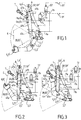
- a front lift device for agricultural tractor comprising a frame 1 adapted to be bolted to the frame of a tractor, and two lower link arms 2 and 2 ', only the left arm 2 being visible.
- Each arm is pivotally mounted about a hinge axis 3, 3 'provided in the lower part of the frame 1.
- a left working cylinder 4a and a right working cylinder 4'a are provided to ensure the lifting stroke or working stroke of the associated arm.
- the working stroke is that for which a tool is coupled to the 8,8 'hitching hands provided at the ends of the arms remote from the frame 1. This working stroke is between a low position illustrated on Fig.1 and a high position illustrated on Fig.2 .
- the rods of the cylinders 4a and 4'a are respectively connected to the arms 2 and 2 'by hinge pins 5-5'.
- the arms 2, 2 ' are bent, in the form of an obtuse angle, with their convexity turned downwards.
- the rod of the cylinder is coupled to the portion of the arm between the joint 3, 3 'on the frame and the elbow of the arm.
- the hinge pins 5, 5 'of the rods on the arms are situated, in the example in question, in front (in the normal direction of progress of the tractor) axes 3.3' articulation of the arms on the chassis.
- the arms could extend rearward axes 3, 3 'and the rods could be connected to the arms behind the axes 3,3'; in this case, the device would be adapted accordingly to the reversal of direction, the rise of the arms being obtained by output of the rod, and the descent by retraction of the rod.
- the device comprises a displacement means A, which can be controlled exclusively by means of a dedicated command located preferably on the outside, suitable for passing the arm or arms 2.2 'in a retracted position illustrated on Fig.3 , more set back than the working position identified illustrated on Fig.2 .
- the transition from the working position to the retracted position is achieved without manual effort.
- the reverse passage from the retracted position to the working position which does not create any risk of interference, can be obtained automatically from the cab or from external controls to actuate the front linkage.
- the moving means A comprises a connecting means L of adjustable length between one of the elements, cylinder or rod, the working cylinder 4a, 4'a and one of the parts constituted by the frame 1 or the arm 2, 2 '.
- the axes 5, 5 'of articulation of the rods on the arms are located in front of the axes 3,3' of articulation of the arms on the chassis; under these conditions, the connecting means L is maintained in an elongated state for the normal working mode ( Fig.1 and 2 ), and is placed in a retracted state ( Fig.3 ) so that the arm or arms 2, 2 'pass to a retracted position.
- the adjustable length connecting means is constituted by a second cylinder 4b, 4'b maintained in the extended position in normal working mode, and controlled in the retracted position for the passage in the retracted position.
- the rods of the cylinders 4b and 4'b are respectively connected to the chassis 1 by hinge pins 6-6 '
- the cylinders 4a-4b and 4'a-4'b are coaxial, with cylinders of the same diameter. They are brought together to form an assembly of two jacks welded end to end by their bottom remote rods, and whose opposite chambers to the piston rod are separated by a partition M.
- the working ram 4a, 4'a corresponds to the part of the assembly having a long stroke used during the work and the second jack 4b, 4'b corresponds to the part of the assembly having a shorter stroke used for the retraction phase out of use, when no tool is hooked to the ends of the arms 2, 2 '.
- Each set of two cylinders 4a-4b and 4'a-4'b consists of four chambers: two chambers 4Ta and 4Tb cylinder rod side, and two chambers 4Fa and 4Fb side barrel, that is opposite side to each rod.
- the rod side chambers 4Ta and 4Tb are interconnected by Ta-Tb pipes, and the barrel side chambers 4Fa and 4Fb are interconnected by Fa-Fb lines which are then connected to the source of pressurized oil generated by the tractor.
- SF and ST isolation valves that allow the connection between 4Ta and 4Tb, and between 4Fa and 4Fb, only when they are controlled, which causes them to be opened. .
- the SF and ST valves are closed and isolate 4Tb from 4Ta, and 4Fb from 4Fa.
- Fig. 1 and 2 show that there is perfect overlapping of the lifting strokes between the low position and the standard high working position, with a tool E (schematically represented by a single line) attached to the lift.
- Fig.3 shows the arms 2-2 'in the retracted position when the cylinders 4a and 4b on the one hand, and 4'a and 4'b on the other hand, are simultaneously retracted, while no tool is hooked to the lift.
- Fig. 3 illustrates the reduction of longitudinal offset RD between the upper working position and the retracted high position.
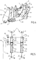
- the cylinders 4a-4b and 4'a-4'b have their respective chambers 4Ta-4'Ta, 4Fa-4'Fa, 4Tb-4'Tb, 4Fb-4'Fb connected together in parallel ( Fig.5 ). In this way only one ST-side isolation valve and one SF-side isolation valve are required.
- a VR lock plate ( Fig.4 ) With the method of connecting the pressurized fluid supply lines according to the invention, it is possible, after dismounting the locking plate VR, to allow the connection of the pressurized fluid supply pipes according to the invention. lateral oscillation allowing relief tracking while carrying the tool connected to the raising by means of the coupling hooks 8-8 'and the third upper point 7 with connecting rod.
- a control switch preferably operable only outside the driver's station, including the dedicated contacts 9F, 9T ( Fig.1 ) preferably with twin action is provided to control the opening of the SF and ST isolation valves and allow the passage of fluid, to go into retracted mode.
- This switch must be operated simultaneously with the command, usually by button, of the source of pressure and flow.
- the elongation of the second cylinder 4b, 4'b, as its shortening, is obtained exclusively by simultaneously actuating the control of the valves SF, ST with the external controls (not shown) of up-down of the working cylinders 4a, 4'a .
- the external controls are generally formed by buttons located outside the cockpit, and can only be operated by a user outside the cabin.
- Another possibility of avoiding an erroneous actuation of the front linkage, when the latter is in the retracted position, is to calibrate the operating range from an angular sensor (not shown) per arm, as commonly used, measuring the angular movement of the lower arms 2, 2 '.
- an angular sensor (not shown) per arm, as commonly used, measuring the angular movement of the lower arms 2, 2 '.
- the components of the double cylinders 4a-4b and 4'a-4'b are of the same dimensions between part a and part b, out of the race, thus simplifying the manufacture and management of spare parts.
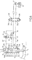
- FIG.6 one can see a particularly advantageous embodiment of the second cylinder 104b of a lift according to the invention, shown summarily.
- the second jack 104b makes it possible to adjust the distance between the frame 1 and the piston 21-rod 22 of the first jack 104a, whereas in the production of Fig.1-3 the second cylinder 4b adjusts the distance between the frame 1 and the cylinder of the first cylinder 4a.
- the second cylinder 104b is coaxial with the first cylinder 104b.
- the cylinder 23b of the second cylinder and 23a of the first cylinder are formed by portions of the same cylinder 23 and are open towards one another.
- a retaining ring 24, in particular formed by an open metal ring, is anchored in the inner wall of the cylinder 23 and marks the separation between the two portions 23a, 23b.
- a removable plate 25, sealed through the rod 21 closes one end of the cylinder, the other end being closed by a bottom 26.
- the second cylinder 104b comprises a floating piston 27 with a head 28 and an extension 29 of smaller diameter which protrudes into the cylinder 23a of the first cylinder 104a.
- the floating piston 27 constitutes a stop for the piston rod assembly of the first jack in the retracted position.
- the retaining ring 24 for stopping the floating piston 27 in the extended position.
- the cylinder 23b of the second jack is hinged to the frame 1 either directly at its upper end, or by an intermediate clevis not shown.
- the rod 22 of the working cylinder 104a is articulated at its lower end on the lifting arm 2.
- Each chamber 30, 31, 32 has in its wall a connection opening to a fluid inlet or outlet pipe, respectively 30 ', 31', 32 '.
- the connecting orifice is located in an area corresponding to the minimum volume of the chamber, namely: in the vicinity of the plate 25 for the orifice of the pipe 30 '; in the vicinity of the ring 24 for the orifice of the pipe 31 '; and in the vicinity of the bottom 26 for the orifice of the pipe 32 '.
- the orifice of the chamber 32 on the bottom side of the second cylinder is connected to a first orifice 33.1 of a three-position distributor 33, with a closed center, via a valve 34 remotely controlled electrically, in particular from a dedicated control preferably located near the external controls and to operate simultaneously.
- the orifice of the intermediate chamber 31 is connected to the same first dispenser orifice 33.1 with the interposition of a non-return valve 35 preventing flow to the chamber 31 from the first dispenser orifice 33.1, but allowing flow in the direction opposite.
- a connecting pipe 36 provided with a valve 37 controlled by the pressure of the bottom-side chamber 32, is connected on the one hand to the pipe 32 'of the orifice of the bottom chamber 32 between the electrically controlled valve 34 and the orifice 33.1 of the distributor, and secondly on the pipe 31 'of the orifice of the intermediate chamber 31, between the non-return valve 35 and the orifice of the intermediate chamber 31.
- the piloted valve 37 s opens when the pressure is sufficient in the bottom chamber 32, and then ensures the supply under pressure of the intermediate chamber 31.
- the rise in pressure is obtained when the abutment of the piston 27 on the ring 24 is reached and ensures the automatic control of the working stroke without specific action avoiding any error of use.
- the valve 37 of the connecting pipe is hydraulically controlled.
- the orifice of the rod-side chamber of the first cylinder 104a is connected by the pipe 30 'to a second orifice 33.2 of the distributor 33.
- the distributor 33 When the distributor 33 is in its closed center position, illustrated on Fig.6 , the chambers 30, 31, 32 are isolated from the pressure source P and the cover B.
- the distributor When the distributor is actuated in the position 33A corresponding to the crossing of the orifices located on both sides of the distributor, the orifice 33.1 is connected to cover B, or exhaust, while port 33.2 is connected to the pressure. The situation is reversed for the other working position 33B of the distributor.
- the operation is as follows.
- the chamber 32 In normal working position of the raising, the chamber 32 is filled with oil, and the floating piston 27 is in abutment against the ring 24.
- the extension 29 occupies its position farthest from the bottom 26 and determines the high end of the piston 21 and the rod 22 of the cylinder 104a for working with a hooked tool.
- the valve 34 is kept closed.
- the rise of the tool attached to the lift is obtained by passage of the distributor 33 in position 33A.
- the pressurized oil is sent into the chamber 30 while the chamber 31 is exhausted.
- the piston 21 can go up.
- the chamber 32 does not empty at the exhaust because the valve 34 remains closed.
- the upper limit of working stroke is limited by the floating piston 27 in the extreme low position.
- the user For the passage in the retracted position, when no tool is attached to the lift, the user simultaneously controls the passage of the distributor 33 in position 33A and the opening of the valve 34.
- the chamber 30 being connected to the pressure, the piston 21 moves away from the plate 25, and the chambers 31, 32 connected to the exhaust are empty.
- the floating piston 27 At the end of the high stroke the floating piston 27 is in abutment against the bottom 26 while the piston 21 is in abutment against the extension 29.
- the arm 2 occupies a retracted position, more raised than the upper working position.
- the passage in the retracted position being obtained only in the absence of tools, the return to the working position is not obtained by gravity which ensures the filling of the bottom chamber 32 thus automatically controlling the working stroke by limiting the rise in the absence of voluntary control of the retraction function.
- Fig.7 illustrates a variant of the realization of Fig.6 .
- the valve 37 controlled hydraulically Fig.6 is replaced by a valve 37a electrically controlled by a switch 38 responsive to the pressure in the bottom chamber 32. When this pressure exceeds a predetermined value, the switch 38 closes and ensures the power supply of the valve 37a which s' opens.
- a manually operated switch (not shown) may be inserted into the power supply line of the valve 37a so that the single-acting mode can be remotely selected with this switch in the open position.
- the invention allows a transition from work mode to retracted mode without any manual effort or loss of time.
- the separation of the working and retracted functions avoids any errors during use.
Landscapes
- Life Sciences & Earth Sciences (AREA)
- Engineering & Computer Science (AREA)
- Mechanical Engineering (AREA)
- Soil Sciences (AREA)
- Environmental Sciences (AREA)
- Zoology (AREA)
- Agronomy & Crop Science (AREA)
- Lifting Devices For Agricultural Implements (AREA)
- Agricultural Machines (AREA)
Claims (16)
- Fronthubvorrichtung für einen insbesondere landwirtschaftlichen Traktor, welche das Ankoppeln und Bedienen eines Werkzeugs ermöglicht, mit:- einem Gestell (1) zum Anbringen an dem Rahmen des Traktors;- zwei unteren Armen (2, 2'), die an dem Rahmen angelenkt sind und an ihrem dem Gestell abgewandten Ende eine Kopplungseinrichtung (8, 8') für das Werkzeug aufweisen;- mindestens einem Arbeitszylinder (4a, 4'a), wobei ein Element desselben, der Zylinder oder die Stange, mit dem Gestell verbunden ist, und das andere Element, die Stange oder der Zylinder, mit einem der Arme verbunden ist, wobei der Arbeitszylinder die Bewegungen des Arms oder der Arme entlang eines Arbeitsweges zwischen einer unteres Position und einer dem normalen Arbeitsmodus entsprechenden angehobenen Position ermöglicht;- einer von einer Steuerung aus steuerbaren Bewegungseinrichtung (A), welch geeignet ist, den Arm oder die Arme in eine zusammengeklappte Position zu überführen, die weiter zurückgezogen ist als die angehobene Arbeitsposition, wobei die Bewegungseinrichtung (A) eine Verbindungseinrichtung (L) mit einstellbarer Länge zwischen einem der Elemente, dem Zylinder oder der Stange, des Arbeitszylinders (4a, 4'a; 104a) und einem der durch das Gestell oder einen Arm gebildeten Teile aufweist,dadurch gekennzeichnet, dass die Verbindungseinrichtung (L) durch einen zweiten Zylinder (4b, 4'b; 104b) gebildet ist, der im normalen Arbeitsmodus in einer ersten, ausgefahrenen oder eingezogenen Position gehalten ist, und für den Übergang in die zusammengeklappte Position in eine zweite, eingezogene oder ausgefahrene Position gesteuert wird, wobei der Übergang von der Arbeitsposition in die zusammengeklappte Position ohne jeglichen manuellen Kraftaufwand erreicht wird,
und dass der zweite Zylinder (4b, 4'b; 104b) mit dem ersten Zylinder (4a, 4'a; 104a) koaxial ist. - Vorrichtung nach Anspruch 1, dadurch gekennzeichnet, dass der Zylinder des zweiten Zylinders (4b, 4'b; 104b) den selben Durchmesser aufweist und denjenigen des ersten Zylinders (4a, 4'a; 104a) verlängert, wobei die Zylinder fest miteinander verbunden sind.
- Vorrichtung nach Anspruch 1 oder 2, dadurch gekennzeichnet, dass der Zylinder (23b) des zweiten Zylinders (104b) und derjenige (23a) des ersten Arbeitszylinders (104a) durch Bereiche desselben Zylinders (23) gebildet sind und zueinander offen sind, wobei ein Rückhaltering (24) in der Innenwand des Zylinders (23) befestigt ist und die Trennung zwischen den beiden Bereichen markiert, und wobei der zweite Zylinder (104b) einen schwimmend gelagerten Kolben (27) mit einem Kopf (28) und einer Verlängerung (29) mit kleinerem Durchmesser aufweist, welche in den Zylinder (23a) des ersten Zylinders (104a) erstreckt und einen Anschlag für die Kolben/Stange-Anordnung des ersten Zylinders in der eingezogenen Position bildet, wobei der Rückhaltering das Anhalten des schwimmend gelagerten Kolbens in der ausgefahrenen Position ermöglicht.
- Vorrichtung nach Anspruch 3, dadurch gekennzeichnet, dass der Zylinder des zweiten Zylinders (104b) an seinem oberen Ende an dem Gestell (1) angelenkt ist, während die Stange (22) des Arbeitszylinders (104a) an seinem unteren Ende an dem Hubarm (2) angelenkt ist.
- Vorrichtung nach einem der Ansprüche 1 bis 3, dadurch gekennzeichnet, dass das Innenvolumen der beiden Zylinder in drei Kammern (30, 31, 32) mit variablem Volumen unterteilt ist, nämlich:- eine Kammer (30) auf Seiten des ersten Arbeitszylinders (104a) zwischen der von der Stange durchquerten Schließplatte (25) und dem Kolben (21) des Arbeitszylinders,- eine Mittelkammer (31) zwischen dem Kolben (21) des Arbeitszylinders und dem schwimmend gelagerten Kolben (27),- und eine Kammer (32) auf Seiten des Bodens des zweiten Arbeitszylinders zwischen dem schwimmend gelagerten Kolben (27) und dem Boden (26) des Zylinders,wobei ein Rückhaltering (24) den Hub des schwimmend gelagerten Kolbens (27) begrenzt,
wobei jede Kammer in ihrer Wand eine Öffnung zur Verbindung mit einer Fluideinlass- oder -auslasskanalsystem aufweist, wobei die Öffnung in einer Zone angeordnet ist, die dem Mindestvolumen der Kammer entspricht. - Vorrichtung nach Anspruch 5, dadurch gekennzeichnet, dass die Druckfluidversorgung in Richtung der auf Seiten des Bodens befindlichen Kammer (32) gerichtet ist, und dass, sobald der Druck in dieser Kammer einen bestimmten Wert erreicht, der sich ergibt, sobald der schwimmend gelagerte Kolben in Anlage an dem Rückhaltering (24) gelangt, die Versorgung der Mittelkammer (31) veranlasst wird, wobei die andere, auf Seiten der Stange befindliche Kammer (30) mit dem Auslass verbunden ist.
- Vorrichtung nach Anspruch 6, dadurch gekennzeichnet, dass:- die Öffnung der auf Seiten des Bodens des zweiten Zylinders (104b) befindlichen Kammer (32) mit einer ersten Verteileröffnung (33.1) über ein elektrisches Steuerventil (34) verbunden ist;- die Öffnung der Mittelkammer (31) mit derselben ersten Verteileröffnung (33.1) unter Zwischenfügung eines Rückschlagklappe (35) verbunden ist, das ein Strömen von der ersten Verteileröffnung (33.1) zu der Kammer (31) verhindert, ein Strömen in der Gegenrichtung jedoch ermöglicht;- eine Verbindungsleitung (36) vorgesehen ist, die mit einem Ventil (37, 37a) versehen ist, das entsprechend dem Druck der auf Seiten des Bodens befindlichen Kammer (32) gesteuert ist, wobei die Verbindungsleitung einerseits von der Leitung der Öffnung der auf Seiten des Bodens befindlichen Kammer (32) zwischen dem elektrisch gesteuerten Ventil (34) und der Verteileröffnung (33.1) und andererseits von der Leitung der Öffnung der Mittelkammer (31) zwischen der Rückschlagklappe (35) und der Verteileröffnung (33.1) abzweigt, wobei sich das gesteuerte Ventil (37, 37.a) öffnet, wenn der Druck in der auf Seiten des Bodens befindlichen Kammer (32) ausreicht, und somit die Druckbeaufschlagung der Mittelkammer (31) gewährleistet.
- Vorrichtung nach Anspruch 7, dadurch gekennzeichnet, dass das Ventil (37) der Versorgungsleitung hydraulisch gesteuert ist.
- Vorrichtung nach Anspruch 7, dadurch gekennzeichnet, dass das Ventil (37a) der Versorgungsleitung durch einen elektrischen Schalter (38) elektrisch gesteuert ist, welcher für den Druck in der Leitung der Öffnung der auf Seiten des Bodens befindlichen Kammer empfindlich ist.
- Vorrichtung nach Anspruch 1 oder 2, dadurch gekennzeichnet, dass die Zylinder (4a, 4'a; 4b, 4'b) getrennte Zylinder aufweisen, die an ihren Böden insbesondere durch Schweißen fest miteinander verbunden sind, wobei ihre Stangen einander gegenüberliegen.
- Vorrichtung nach Anspruch 10, dadurch gekennzeichnet, dass die Stange des zweiten Zylinders (4b, 4'b) an seinem oberen Ende an dem Gestell (1) angelenkt ist, während die Stange des Arbeitszylinders (4a, 4'a) an seinem unteren Ende an dem Hubarm (2, 2') angelenkt ist.
- Vorrichtung nach einem der Ansprüche 1 bis 6, dadurch gekennzeichnet, dass sie einen Arbeitszylinder (4a, 4'a; 104a) und einen zweiten Zylinder (4b, 4'b; 104b) aufweist, die jedem der Hubarme zugeordnet sind.
- Vorrichtung nach einem der vorhergehenden Ansprüche, dadurch gekennzeichnet, dass die Kammern (4Tb, 4Fb) des zweiten Zylinders (4b) parallel mit denen (4Ta, 4Fa) des Arbeitszylinders (4a) unter Zwischenfügung eines Ventils (ST; SF) verbunden sind, welches es ermöglicht, in der Schließstellung die Kammern des zweiten Zylinders (4b) von denen des Arbeitszylinders (4a) zu isolieren.
- Vorrichtung nach einem der vorhergehenden Ansprüche, dadurch gekennzeichnet, dass sie einen Schalter (9F, 9T) aufweist, der um Steuern des Übergangs in die eingeklappte Position gleichzeitig mit einem Steuerknopf für das Anheben des Arbeitszylinders (4a, 4'a) zu betätigen ist, um jede Gefahr einer gegenseitigen Störung des Arbeitsmodus und des Zusammenklappmodus zu vermeiden.
- Vorrichtung nach einem der vorhergehenden Ansprüche, dadurch gekennzeichnet, dass sie mindestens einen Sensor (DP, DP') aufweist, der für die zusammengeklappte Position der Hubeinrichtung empfindlich ist, um den Kabinenbetrieb erst freizugeben, wenn der zweite Zylinder (4b, 4'b) sich in der ausgefahrenen Position befindet.
- Vorrichtung nach einem der vorhergehenden Ansprüche, dadurch gekennzeichnet, dass einen Winkelpositionssensor für eine automatische Kontrolle aufweist, derart, dass bei der Durchführung der Kalibrierung des Betriebsbereichs des Sensors allein unter Bezugnahme auf den Arbeitshub der Arbeitszylindern (4a, 4'a), bei sich in der ausgefahrenen Position befindlichen zweiten Zylindern (4b, 4'b), jede Steuerung von der Kabine des Traktors aus untersagt ist, wenn die Bewegung des Positionssensors eine Bewegung aus dem Kalibrierungsbereich heraus anzeigt.
Applications Claiming Priority (2)
| Application Number | Priority Date | Filing Date | Title |
|---|---|---|---|
| FR0806039A FR2937827B1 (fr) | 2008-10-30 | 2008-10-30 | Dispositif de relevage avant pour tracteur. |
| PCT/IB2009/054770 WO2010049896A2 (fr) | 2008-10-30 | 2009-10-28 | Dispositif de relevage avant pour tracteur |
Publications (2)
| Publication Number | Publication Date |
|---|---|
| EP2364077A2 EP2364077A2 (de) | 2011-09-14 |
| EP2364077B1 true EP2364077B1 (de) | 2016-05-11 |
Family
ID=40433636
Family Applications (1)
| Application Number | Title | Priority Date | Filing Date |
|---|---|---|---|
| EP09756835.6A Not-in-force EP2364077B1 (de) | 2008-10-30 | 2009-10-28 | Fronthubvorrichtung für einen traktor |
Country Status (6)
| Country | Link |
|---|---|
| US (1) | US8926256B2 (de) |
| EP (1) | EP2364077B1 (de) |
| CA (1) | CA2740435A1 (de) |
| FR (1) | FR2937827B1 (de) |
| RU (1) | RU2523850C2 (de) |
| WO (1) | WO2010049896A2 (de) |
Families Citing this family (10)
| Publication number | Priority date | Publication date | Assignee | Title |
|---|---|---|---|---|
| DK2625943T3 (da) * | 2012-02-13 | 2014-09-15 | Mähler & Söner Ab | Et redskab |
| US9352944B2 (en) | 2012-03-19 | 2016-05-31 | Gray Manufacturing Company, Inc. | Control and communication system for a wireless vehicle lift system |
| ITPD20130161A1 (it) * | 2013-06-05 | 2014-12-06 | Carraro Antonio Spa | Dispositivo di sollevamento e sospensione di attrezzature agricole da traino per trattori e macchine simili |
| CN104514236A (zh) * | 2013-10-01 | 2015-04-15 | 迪尔公司 | 前端装载机结构 |
| FR3030183B1 (fr) * | 2014-12-19 | 2017-01-13 | Noremat | Equipement pour la coupe de vegetaux autorisant un escamotage bidirectionnel d'un bras portant un outil de coupe |
| FR3037769B1 (fr) * | 2015-06-23 | 2017-07-21 | Hubert Defrancq | Dispositif de relevage avant pour engin agricole et procede de commande associe. |
| IT201700056889U1 (it) * | 2017-05-25 | 2018-11-25 | Faster Spa | Attacco per applicazioni oleodinamiche equipaggiato con almeno un sensore di rilevamento |
| CN112335363A (zh) * | 2020-10-30 | 2021-02-09 | 甘肃农业大学 | 一种机具快速换接装置及方法 |
| CN114041339A (zh) * | 2021-11-15 | 2022-02-15 | 日照海卓液压有限公司 | 大型动力平台用三轴多姿态控制悬挂提升装置 |
| CN116902833B (zh) * | 2023-08-02 | 2025-08-29 | 湖南星邦智能装备股份有限公司 | 一种折臂装置及其折臂连接体 |
Family Cites Families (11)
| Publication number | Priority date | Publication date | Assignee | Title |
|---|---|---|---|---|
| US4181181A (en) * | 1977-11-21 | 1980-01-01 | Massey-Ferguson Inc. | Tractor implement hitch with rubbing surfaces to limit sway |
| US4216975A (en) | 1978-12-11 | 1980-08-12 | Deere & Company | Tractor hitch |
| FR2448843A1 (fr) * | 1979-02-16 | 1980-09-12 | Lemoine Attelages Sa | Attelage " trois points " utilisable aussi bien a l'avant qu'a l'arriere d'un vehicule industriel, agricole, pour travaux publics, ou forestier, par exemple un tracteur |
| DE3439048C2 (de) * | 1984-10-25 | 1986-09-11 | Deere & Co., Moline, Ill., US, Niederlassung Deere & Co. European Office, 6800 Mannheim | Kraftheber für ein Hubgerät |
| US4899831A (en) * | 1986-12-22 | 1990-02-13 | J. I. Case Company | Frontal connection apparatus for tractors |
| FR2688378B1 (fr) | 1992-03-12 | 1996-09-06 | Hubert Defrancq | Dispositif de relevage avant, pour tracteur agricole ou analogue, et porte-masse pour un tel dispositif |
| FR2758938B1 (fr) * | 1997-02-03 | 1999-04-23 | Kuhn Sa | Reglage automatique de l'allegement d'une unite de travail d'une machine : procede, dispositif et machine |
| DE29901460U1 (de) * | 1998-01-28 | 2000-09-21 | Wiedenmann GmbH, 89192 Rammingen | Frontkraftheber für den Anschluß eines Frontgerätes an einen Traktor |
| EP1018292B8 (de) * | 1999-01-09 | 2005-06-29 | GKN Walterscheid GmbH | Hubwerk für die Unterlenker einer Anbauvorrichtung eines Traktors |
| GB2398720B (en) * | 2003-02-27 | 2006-04-12 | Agco Gmbh & Co | Lifting unit for the lower links of a tractor |
| RU2282959C2 (ru) * | 2004-10-12 | 2006-09-10 | Республиканское унитарное предприятие "Минский тракторный завод" | Устройство для крепления навесного оборудования к транспортному средству |
-
2008
- 2008-10-30 FR FR0806039A patent/FR2937827B1/fr not_active Expired - Fee Related
-
2009
- 2009-10-28 US US13/126,891 patent/US8926256B2/en not_active Expired - Fee Related
- 2009-10-28 WO PCT/IB2009/054770 patent/WO2010049896A2/fr not_active Ceased
- 2009-10-28 CA CA2740435A patent/CA2740435A1/fr not_active Abandoned
- 2009-10-28 EP EP09756835.6A patent/EP2364077B1/de not_active Not-in-force
- 2009-10-28 RU RU2011121347/13A patent/RU2523850C2/ru not_active IP Right Cessation
Also Published As
| Publication number | Publication date |
|---|---|
| US20110262255A1 (en) | 2011-10-27 |
| CA2740435A1 (fr) | 2010-05-06 |
| FR2937827A1 (fr) | 2010-05-07 |
| US8926256B2 (en) | 2015-01-06 |
| EP2364077A2 (de) | 2011-09-14 |
| WO2010049896A2 (fr) | 2010-05-06 |
| FR2937827B1 (fr) | 2013-02-15 |
| WO2010049896A3 (fr) | 2011-07-07 |
| RU2523850C2 (ru) | 2014-07-27 |
| RU2011121347A (ru) | 2012-12-10 |
Similar Documents
| Publication | Publication Date | Title |
|---|---|---|
| EP2364077B1 (de) | Fronthubvorrichtung für einen traktor | |
| CA2428771C (en) | Arrangement for securing an implement to a lifting arm | |
| CA3031825C (fr) | Atterrisseur a contrefiche a lumiere | |
| US20160137470A1 (en) | Lifting apparatus for lifting and lowering vehicles | |
| FR2718168A1 (fr) | Appareil de support pour l'accouplement et désaccouplement d'un chargeur frontal. | |
| EP3313164B1 (de) | Fronthubvorrichtung für eine landwirtschaftliche maschine und zugehöriges steuerungsverfahren | |
| FR2649580A1 (fr) | Systeme d'attelage et de relevage pour un outil, notamment agricole, propre a etre monte a l'avant d'un tracteur | |
| EP1960248B1 (de) | Greifvorrichtung, insbesondere für sportwagen, kinderwagen und dergleichen | |
| EP0772382B1 (de) | Regelungsvorrichtung für schleppergeschobenes landwirtschaftliches gerät | |
| EP1932717B1 (de) | Hydraulische Verschlussvorrichtung für einen Hubarm | |
| CA2378609A1 (fr) | Appareil de manutention d'une charge et vehicule le comportant | |
| EP2959759B1 (de) | Landwirtschaftliche maschine, die mit einer zentriervorrichtung ausgestattet ist | |
| JP7155072B2 (ja) | 作業機の油圧システム及び作業機 | |
| FR2753161A1 (fr) | Dispositif de commande de braquage force des roues d'une remorque | |
| FR2611687A1 (fr) | Dispositif de commande hydraulique de remplissage de citerne | |
| US8834090B1 (en) | Grappling fork attachment system | |
| EP1679282B1 (de) | Kran mit ausgeglichenem Hauptausleger und Hilfsausleger, der senkrecht gehalten werden kann | |
| FR2938401A1 (fr) | Machine agricole destinee a etre rapportee sur un tracteur et comportant un verin de levage et un verin de delestage d'une unite de travail | |
| EP3868189B1 (de) | Gelenkzugarmvorrichtung und mit einem solchen arm ausgestattete landwirtschaftliche maschine | |
| FR2731729A1 (fr) | Systeme de commande hydraulique pour chargeur | |
| CH403375A (fr) | Mécanisme de relevage hydraulique pour tracteurs agricoles | |
| JP4070473B2 (ja) | クレーン車のジブ格納装置 | |
| EP3363287A1 (de) | Auslegervorrichtung für landwirtschaftliche spritzgeräte, landwirtschaftliches spritzgerät und verfahren zum betreiben einer entsprechenden auslegervorrichtung | |
| FR2596378A1 (fr) | Dispositif chargeur a compensation rapide et blocage pour tracteurs agricoles et analogues | |
| EP1053670A1 (de) | Böschungsmäher |
Legal Events
| Date | Code | Title | Description |
|---|---|---|---|
| PUAI | Public reference made under article 153(3) epc to a published international application that has entered the european phase |
Free format text: ORIGINAL CODE: 0009012 |
|
| 17P | Request for examination filed |
Effective date: 20110429 |
|
| AK | Designated contracting states |
Kind code of ref document: A2 Designated state(s): AT BE BG CH CY CZ DE DK EE ES FI FR GB GR HR HU IE IS IT LI LT LU LV MC MK MT NL NO PL PT RO SE SI SK SM TR |
|
| DAX | Request for extension of the european patent (deleted) | ||
| GRAP | Despatch of communication of intention to grant a patent |
Free format text: ORIGINAL CODE: EPIDOSNIGR1 |
|
| INTG | Intention to grant announced |
Effective date: 20151201 |
|
| GRAS | Grant fee paid |
Free format text: ORIGINAL CODE: EPIDOSNIGR3 |
|
| GRAA | (expected) grant |
Free format text: ORIGINAL CODE: 0009210 |
|
| AK | Designated contracting states |
Kind code of ref document: B1 Designated state(s): AT BE BG CH CY CZ DE DK EE ES FI FR GB GR HR HU IE IS IT LI LT LU LV MC MK MT NL NO PL PT RO SE SI SK SM TR |
|
| REG | Reference to a national code |
Ref country code: GB Ref legal event code: FG4D Free format text: NOT ENGLISH |
|
| REG | Reference to a national code |
Ref country code: CH Ref legal event code: EP |
|
| REG | Reference to a national code |
Ref country code: AT Ref legal event code: REF Ref document number: 797873 Country of ref document: AT Kind code of ref document: T Effective date: 20160515 |
|
| REG | Reference to a national code |
Ref country code: IE Ref legal event code: FG4D Free format text: LANGUAGE OF EP DOCUMENT: FRENCH |
|
| REG | Reference to a national code |
Ref country code: DE Ref legal event code: R096 Ref document number: 602009038612 Country of ref document: DE |
|
| REG | Reference to a national code |
Ref country code: NL Ref legal event code: FP |
|
| REG | Reference to a national code |
Ref country code: LT Ref legal event code: MG4D |
|
| REG | Reference to a national code |
Ref country code: FR Ref legal event code: PLFP Year of fee payment: 8 |
|
| PG25 | Lapsed in a contracting state [announced via postgrant information from national office to epo] |
Ref country code: FI Free format text: LAPSE BECAUSE OF FAILURE TO SUBMIT A TRANSLATION OF THE DESCRIPTION OR TO PAY THE FEE WITHIN THE PRESCRIBED TIME-LIMIT Effective date: 20160511 Ref country code: LT Free format text: LAPSE BECAUSE OF FAILURE TO SUBMIT A TRANSLATION OF THE DESCRIPTION OR TO PAY THE FEE WITHIN THE PRESCRIBED TIME-LIMIT Effective date: 20160511 Ref country code: NO Free format text: LAPSE BECAUSE OF FAILURE TO SUBMIT A TRANSLATION OF THE DESCRIPTION OR TO PAY THE FEE WITHIN THE PRESCRIBED TIME-LIMIT Effective date: 20160811 |
|
| REG | Reference to a national code |
Ref country code: AT Ref legal event code: MK05 Ref document number: 797873 Country of ref document: AT Kind code of ref document: T Effective date: 20160511 |
|
| PG25 | Lapsed in a contracting state [announced via postgrant information from national office to epo] |
Ref country code: SE Free format text: LAPSE BECAUSE OF FAILURE TO SUBMIT A TRANSLATION OF THE DESCRIPTION OR TO PAY THE FEE WITHIN THE PRESCRIBED TIME-LIMIT Effective date: 20160511 Ref country code: HR Free format text: LAPSE BECAUSE OF FAILURE TO SUBMIT A TRANSLATION OF THE DESCRIPTION OR TO PAY THE FEE WITHIN THE PRESCRIBED TIME-LIMIT Effective date: 20160511 Ref country code: ES Free format text: LAPSE BECAUSE OF FAILURE TO SUBMIT A TRANSLATION OF THE DESCRIPTION OR TO PAY THE FEE WITHIN THE PRESCRIBED TIME-LIMIT Effective date: 20160511 Ref country code: GR Free format text: LAPSE BECAUSE OF FAILURE TO SUBMIT A TRANSLATION OF THE DESCRIPTION OR TO PAY THE FEE WITHIN THE PRESCRIBED TIME-LIMIT Effective date: 20160812 Ref country code: PT Free format text: LAPSE BECAUSE OF FAILURE TO SUBMIT A TRANSLATION OF THE DESCRIPTION OR TO PAY THE FEE WITHIN THE PRESCRIBED TIME-LIMIT Effective date: 20160912 Ref country code: LV Free format text: LAPSE BECAUSE OF FAILURE TO SUBMIT A TRANSLATION OF THE DESCRIPTION OR TO PAY THE FEE WITHIN THE PRESCRIBED TIME-LIMIT Effective date: 20160511 |
|
| PG25 | Lapsed in a contracting state [announced via postgrant information from national office to epo] |
Ref country code: IT Free format text: LAPSE BECAUSE OF FAILURE TO SUBMIT A TRANSLATION OF THE DESCRIPTION OR TO PAY THE FEE WITHIN THE PRESCRIBED TIME-LIMIT Effective date: 20160511 |
|
| PG25 | Lapsed in a contracting state [announced via postgrant information from national office to epo] |
Ref country code: DK Free format text: LAPSE BECAUSE OF FAILURE TO SUBMIT A TRANSLATION OF THE DESCRIPTION OR TO PAY THE FEE WITHIN THE PRESCRIBED TIME-LIMIT Effective date: 20160511 Ref country code: EE Free format text: LAPSE BECAUSE OF FAILURE TO SUBMIT A TRANSLATION OF THE DESCRIPTION OR TO PAY THE FEE WITHIN THE PRESCRIBED TIME-LIMIT Effective date: 20160511 Ref country code: SK Free format text: LAPSE BECAUSE OF FAILURE TO SUBMIT A TRANSLATION OF THE DESCRIPTION OR TO PAY THE FEE WITHIN THE PRESCRIBED TIME-LIMIT Effective date: 20160511 Ref country code: RO Free format text: LAPSE BECAUSE OF FAILURE TO SUBMIT A TRANSLATION OF THE DESCRIPTION OR TO PAY THE FEE WITHIN THE PRESCRIBED TIME-LIMIT Effective date: 20160511 Ref country code: CZ Free format text: LAPSE BECAUSE OF FAILURE TO SUBMIT A TRANSLATION OF THE DESCRIPTION OR TO PAY THE FEE WITHIN THE PRESCRIBED TIME-LIMIT Effective date: 20160511 |
|
| REG | Reference to a national code |
Ref country code: DE Ref legal event code: R097 Ref document number: 602009038612 Country of ref document: DE |
|
| PG25 | Lapsed in a contracting state [announced via postgrant information from national office to epo] |
Ref country code: PL Free format text: LAPSE BECAUSE OF FAILURE TO SUBMIT A TRANSLATION OF THE DESCRIPTION OR TO PAY THE FEE WITHIN THE PRESCRIBED TIME-LIMIT Effective date: 20160511 Ref country code: BE Free format text: LAPSE BECAUSE OF NON-PAYMENT OF DUE FEES Effective date: 20161031 Ref country code: SM Free format text: LAPSE BECAUSE OF FAILURE TO SUBMIT A TRANSLATION OF THE DESCRIPTION OR TO PAY THE FEE WITHIN THE PRESCRIBED TIME-LIMIT Effective date: 20160511 Ref country code: AT Free format text: LAPSE BECAUSE OF FAILURE TO SUBMIT A TRANSLATION OF THE DESCRIPTION OR TO PAY THE FEE WITHIN THE PRESCRIBED TIME-LIMIT Effective date: 20160511 |
|
| PLBE | No opposition filed within time limit |
Free format text: ORIGINAL CODE: 0009261 |
|
| STAA | Information on the status of an ep patent application or granted ep patent |
Free format text: STATUS: NO OPPOSITION FILED WITHIN TIME LIMIT |
|
| 26N | No opposition filed |
Effective date: 20170214 |
|
| PG25 | Lapsed in a contracting state [announced via postgrant information from national office to epo] |
Ref country code: SI Free format text: LAPSE BECAUSE OF FAILURE TO SUBMIT A TRANSLATION OF THE DESCRIPTION OR TO PAY THE FEE WITHIN THE PRESCRIBED TIME-LIMIT Effective date: 20160511 |
|
| REG | Reference to a national code |
Ref country code: CH Ref legal event code: PL |
|
| PG25 | Lapsed in a contracting state [announced via postgrant information from national office to epo] |
Ref country code: MC Free format text: LAPSE BECAUSE OF FAILURE TO SUBMIT A TRANSLATION OF THE DESCRIPTION OR TO PAY THE FEE WITHIN THE PRESCRIBED TIME-LIMIT Effective date: 20160511 |
|
| REG | Reference to a national code |
Ref country code: IE Ref legal event code: MM4A |
|
| PG25 | Lapsed in a contracting state [announced via postgrant information from national office to epo] |
Ref country code: LI Free format text: LAPSE BECAUSE OF NON-PAYMENT OF DUE FEES Effective date: 20161031 Ref country code: CH Free format text: LAPSE BECAUSE OF NON-PAYMENT OF DUE FEES Effective date: 20161031 |
|
| PG25 | Lapsed in a contracting state [announced via postgrant information from national office to epo] |
Ref country code: LU Free format text: LAPSE BECAUSE OF NON-PAYMENT OF DUE FEES Effective date: 20161028 |
|
| REG | Reference to a national code |
Ref country code: FR Ref legal event code: PLFP Year of fee payment: 9 |
|
| PG25 | Lapsed in a contracting state [announced via postgrant information from national office to epo] |
Ref country code: IE Free format text: LAPSE BECAUSE OF NON-PAYMENT OF DUE FEES Effective date: 20161028 |
|
| REG | Reference to a national code |
Ref country code: BE Ref legal event code: MM Effective date: 20161031 |
|
| PGFP | Annual fee paid to national office [announced via postgrant information from national office to epo] |
Ref country code: GB Payment date: 20171019 Year of fee payment: 9 |
|
| PG25 | Lapsed in a contracting state [announced via postgrant information from national office to epo] |
Ref country code: HU Free format text: LAPSE BECAUSE OF FAILURE TO SUBMIT A TRANSLATION OF THE DESCRIPTION OR TO PAY THE FEE WITHIN THE PRESCRIBED TIME-LIMIT; INVALID AB INITIO Effective date: 20091028 Ref country code: CY Free format text: LAPSE BECAUSE OF FAILURE TO SUBMIT A TRANSLATION OF THE DESCRIPTION OR TO PAY THE FEE WITHIN THE PRESCRIBED TIME-LIMIT Effective date: 20160511 |
|
| PG25 | Lapsed in a contracting state [announced via postgrant information from national office to epo] |
Ref country code: TR Free format text: LAPSE BECAUSE OF FAILURE TO SUBMIT A TRANSLATION OF THE DESCRIPTION OR TO PAY THE FEE WITHIN THE PRESCRIBED TIME-LIMIT Effective date: 20160511 Ref country code: MT Free format text: LAPSE BECAUSE OF FAILURE TO SUBMIT A TRANSLATION OF THE DESCRIPTION OR TO PAY THE FEE WITHIN THE PRESCRIBED TIME-LIMIT Effective date: 20160511 Ref country code: IS Free format text: LAPSE BECAUSE OF FAILURE TO SUBMIT A TRANSLATION OF THE DESCRIPTION OR TO PAY THE FEE WITHIN THE PRESCRIBED TIME-LIMIT Effective date: 20160511 Ref country code: MK Free format text: LAPSE BECAUSE OF FAILURE TO SUBMIT A TRANSLATION OF THE DESCRIPTION OR TO PAY THE FEE WITHIN THE PRESCRIBED TIME-LIMIT Effective date: 20160511 |
|
| PG25 | Lapsed in a contracting state [announced via postgrant information from national office to epo] |
Ref country code: BG Free format text: LAPSE BECAUSE OF FAILURE TO SUBMIT A TRANSLATION OF THE DESCRIPTION OR TO PAY THE FEE WITHIN THE PRESCRIBED TIME-LIMIT Effective date: 20160511 |
|
| REG | Reference to a national code |
Ref country code: FR Ref legal event code: PLFP Year of fee payment: 10 |
|
| GBPC | Gb: european patent ceased through non-payment of renewal fee |
Effective date: 20181028 |
|
| PG25 | Lapsed in a contracting state [announced via postgrant information from national office to epo] |
Ref country code: GB Free format text: LAPSE BECAUSE OF NON-PAYMENT OF DUE FEES Effective date: 20181028 |
|
| PGFP | Annual fee paid to national office [announced via postgrant information from national office to epo] |
Ref country code: NL Payment date: 20201028 Year of fee payment: 12 |
|
| PGFP | Annual fee paid to national office [announced via postgrant information from national office to epo] |
Ref country code: DE Payment date: 20211020 Year of fee payment: 13 |
|
| REG | Reference to a national code |
Ref country code: NL Ref legal event code: MM Effective date: 20211101 |
|
| PG25 | Lapsed in a contracting state [announced via postgrant information from national office to epo] |
Ref country code: NL Free format text: LAPSE BECAUSE OF NON-PAYMENT OF DUE FEES Effective date: 20211101 |
|
| PGFP | Annual fee paid to national office [announced via postgrant information from national office to epo] |
Ref country code: FR Payment date: 20221026 Year of fee payment: 14 |
|
| REG | Reference to a national code |
Ref country code: DE Ref legal event code: R119 Ref document number: 602009038612 Country of ref document: DE |
|
| PG25 | Lapsed in a contracting state [announced via postgrant information from national office to epo] |
Ref country code: DE Free format text: LAPSE BECAUSE OF NON-PAYMENT OF DUE FEES Effective date: 20230503 |
|
| PG25 | Lapsed in a contracting state [announced via postgrant information from national office to epo] |
Ref country code: FR Free format text: LAPSE BECAUSE OF NON-PAYMENT OF DUE FEES Effective date: 20231031 |