EP2364857A2 - Appareil d'impression - Google Patents
Appareil d'impression Download PDFInfo
- Publication number
- EP2364857A2 EP2364857A2 EP11157902A EP11157902A EP2364857A2 EP 2364857 A2 EP2364857 A2 EP 2364857A2 EP 11157902 A EP11157902 A EP 11157902A EP 11157902 A EP11157902 A EP 11157902A EP 2364857 A2 EP2364857 A2 EP 2364857A2
- Authority
- EP
- European Patent Office
- Prior art keywords
- platen
- medium
- print apparatus
- support member
- furnished
- Prior art date
- Legal status (The legal status is an assumption and is not a legal conclusion. Google has not performed a legal analysis and makes no representation as to the accuracy of the status listed.)
- Granted
Links
Images



Classifications
-
- B—PERFORMING OPERATIONS; TRANSPORTING
- B41—PRINTING; LINING MACHINES; TYPEWRITERS; STAMPS
- B41J—TYPEWRITERS; SELECTIVE PRINTING MECHANISMS, i.e. MECHANISMS PRINTING OTHERWISE THAN FROM A FORME; CORRECTION OF TYPOGRAPHICAL ERRORS
- B41J11/00—Devices or arrangements of selective printing mechanisms, e.g. ink-jet printers or thermal printers, for supporting or handling copy material in sheet or web form
- B41J11/0045—Guides for printing material
-
- B—PERFORMING OPERATIONS; TRANSPORTING
- B41—PRINTING; LINING MACHINES; TYPEWRITERS; STAMPS
- B41J—TYPEWRITERS; SELECTIVE PRINTING MECHANISMS, i.e. MECHANISMS PRINTING OTHERWISE THAN FROM A FORME; CORRECTION OF TYPOGRAPHICAL ERRORS
- B41J11/00—Devices or arrangements of selective printing mechanisms, e.g. ink-jet printers or thermal printers, for supporting or handling copy material in sheet or web form
- B41J11/26—Pin feeds
- B41J11/34—Guides coacting with pin feeds
-
- B—PERFORMING OPERATIONS; TRANSPORTING
- B41—PRINTING; LINING MACHINES; TYPEWRITERS; STAMPS
- B41J—TYPEWRITERS; SELECTIVE PRINTING MECHANISMS, i.e. MECHANISMS PRINTING OTHERWISE THAN FROM A FORME; CORRECTION OF TYPOGRAPHICAL ERRORS
- B41J11/00—Devices or arrangements of selective printing mechanisms, e.g. ink-jet printers or thermal printers, for supporting or handling copy material in sheet or web form
- B41J11/48—Apparatus for condensed record, tally strip, or like work using two or more papers, or sets of papers, e.g. devices for switching over from handling of copy material in sheet form to handling of copy material in continuous form and vice versa or point-of-sale printers comprising means for printing on continuous copy material, e.g. journal for tills, and on single sheets, e.g. cheques or receipts
- B41J11/485—Means for selecting a type of copy material amongst different types of copy material in the printing apparatus
Definitions
- the invention relates to a print apparatus such as a printer that performs print on a cut sheet and on a continuous paper, and the like.
- a printer as a former print apparatus comprises a platen; a movable guide that is furnished opposite to the platen through a fixed interval and capable of rotating; two pressure rollers those are supported capable of rotating by the movable guide and those press the outer surface of the platen; a push tractor that feeds a continuous paper between the platen and the movable guide; and a sheet guide that is placed above the push tractor and that feeds a cut sheet between the platen and the movable guide, when it feeds the cut sheet between the platen and the movable guide, it presses the platen through the two pressure rollers, while it makes the platen opposite to the movable guide through a fixed interval; and when it feeds the continuous paper, it makes the push tractor side of the movable guide rotate in a direction separating from the platen through a mode change lever, makes the pressure roller on the upstream side in a paper feeding direction separate from the platen by making the interval between the platen and the movable guide larger, and presses the platen through the pressure roller on
- an object of the invention to provide a print apparatus that supplies a means to feed a medium with suppressing its swelling caused by the perforations or the crease that can solve the above problem.
- an aspect of the invention is to provide a print apparatus, comprising: a platen that is furnished opposite to a printing section; a medium support member that is furnished capable of changing an interval from the platen, and that supports a record medium toward the platen; and a medium support auxiliary member that is furnished on the opposite side to the platen in the medium support member, wherein the medium support auxiliary member, when the medium support member is made to separate from the platen, protrudes from the medium support member.
- a print mechanism of a printer as a print apparatus of the present embodiment is composed capable of printing on both of a cut sheet as a record medium and a continuous paper that continuously connects a plurality of paper sheets with perforations or creases (herein after: paper in the case that it is unnecessary to distinguish the cut sheet and the continuous paper), and comprises structures as shown in Fig. 1 .
- Fig. 1 and Fig. 2 1 is a printing section of the print mechanism, comprises a print head 2 that furnishes a plurality of print pins per dot those are composed of super steel wire, a career 3 that mounts the print head 2 and that is formed capable of reciprocating on a career rail 3a placed in a direction perpendicular to a paper feeding direction (referring to Fig. 8 and Fig. 12 , a direction that winds paper around a platen 4 in a clockwise direction from the right side in Fig. 1 ), and the like, and is placed opposite to the front side (the left side in Fig. 1 ) of the platen 4.
- the supply of paper for print use to the printing section 1 of the present embodiment is performed from the rear side (the right side in Fig. 1 ).
- the platen 4 is supported capable of rotating by a main frame of the printer (not shown), and has a function to generate sufficient transfer power onto paper by stopping stroke of the print pins in the print head 2.
- 5a is a push tractor, in which a plurality of sprocket pins erected on the outside of a belt that rotates through a driving means such as motor and the like (not shown) is furnished, and by fitting the sprocket pins into sprocket holes furnished at the side edge parts of the both sides along the paper feeding direction of the continuous paper, it becomes possible to convey the continuous paper in a direction of the platen 4, that is, a continuous paper feeding direction.
- 5b is a sheet guide, is attached to an up cover (not shown) of the printer and is placed above the push tractor 5a, in which the cut sheet is made to drop to the direction of the platen 4, that is, a cut sheet feeding direction owing to its weight.
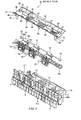
- a paper guide assembly is placed below the platen 4 by being fixed on the main frame through a lower beam 6a, and to whose paper guide body 7, as shown in Fig. 3 , a roller assembly 10 for paper conveyance use, a movable guide 30 as a medium support member that forms a paper conveyance route between the platen 4, a camshaft 40 that switches a paper feeding mode of paper to feed, and the like are attached.
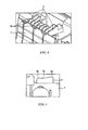
- a stopper portion 7a is furnished on the push tractor 5a side above the paper guide body 7, above which, on the opposite side across the platen 4 and the movable guide 30, a plurality of guide ribs 8 as medium support auxiliary members are furnished (referring to Fig. 3 ), and in the guide rib 8, as shown in Fig. 4 , a guide surface 8a on the platen 4 side becomes an R convex shape in a direction separating from the platen 4 in order not to be a load in paper conveyance time, further, at the corner of the R shape, a chamfered shape 8b is made in order not to catch paper (referring to Fig. 5 ).
- a mode switch lever is a lever that is operated when a paper feeding mode is switched, as shown in Fig. 2 , is supported capable of rotating around a fulcrum hole 9a in which a fulcrum axle of a main frame (not shown) is fit, moves in response to the movement of a mode change gear 9b attached to the tip part of the camshaft 40 through a gear line (not shown), and has a function to switch the paper feeding mode into a cut sheet mode that serves a kind of fed paper as a cut sheet and into a continuous paper mode that serves it as a continuous paper by making the mode switch lever 9 rotate to the rear side or the front side and making the camshaft 40 rotate through the mode switch gear 9b,
- a first pressure roller 12 that is supported capable of rotating by a bearing portion 12a erected on a top plate 11a of a roller frame 11, a second pressure roller 14 that is supported capable of rotating on the upper part of a roller holder 13 (referring to Fig. 6 ), a first spring member 15 such as a compression coil spring and the like, and the like are assembled, and on the condition that they are impelled in the direction of the platen 4 through the first spring member 15, they are accommodated capable of up-and-down moving in an accommodation hole 17 furnished on the paper guide body 7 (referring to Fig. 3 ).
- the roller holder 13 as shown in Fig. 6 , on whose both sides an oval-shaped projecting portion 20 is furnished and on whose lower part a claw portion 21 is furnished, and a second spring member 23 such as a compression coil spring and the like is furnished on the lower part of the roller holder 13, is inserted in a holder hole 27 by fitting the projecting portion 20 into a rectangular fitting ditch (not shown) furnished on the roller frame 11 and engaging the claw portion 21 with a rectangular engagement hole 25 furnished on the roller frame 11 (referring to Fig. 9 and Fig. 13 ).
- a rectangular insertion hole 28 in which the camshaft 40 is inserted is furnished.
- the movable guide 30 is, as shown in Fig. 3 , a plate-like member in that a fulcrum axle 31 furnished on its both sides of the downstream side in the paper feeding direction is fit into a fulcrum hole 31a furnished on the paper guide body 7 and that is supported capable of rotating around the fulcrum axle 31, its guide surface 32 on the platen 4 side is formed into an R convex shape in a direction separating from the platen 4, and a guide portion 33 that guides paper in paper feeding time is furnished on the upstream side of the guide surface 32, that is attached to the upper part, that is, the platen 4 side of the paper guide body 7 by engaging a hook portion 34 furnished on the end of the downstream side in the paper feeding direction with a rib (not shown ) furnished on the paper guide body 7.
- a lever portion 35 for making the movable guide 30 rotate to a continuous paper feeding position (referring to Fig. 12 ) is furnished on the both sides of its end of the downstream side in the paper feeding direction, and a positioning projection 36 for positioning the movable guide 30 on a cut sheet feeding position (referring to Fig. 8 ) is furnished on the upstream side of the lever portion 35.
- a window portion 37 that makes the first pressure roller 12 protrude is furnished on the upstream side
- a notch portion 38 that makes the second pressure roller 14 protrude is furnished on the downstream side
- a plurality of slits 39 are formed as apertures that make the guide rib furnished on the paper guide body 7 protrude when the movable guide 30 rotates to the continuous paper feeding position.
- the camshaft 40 as shown in Fig. 2 , is supported capable of rotating by a bearing portion 40a (referring to Fig. 3 ) furnished on a center part of the both sides of the paper guide body 7, and is attached to the paper guide body 7 on the condition that it is inserted into the insertion hole 28 of the roller assembly 10 accommodated in the accommodation hole 17.
- a first cam 41 (referring to Fig. 8 ) that makes the movable guide 30 rotate to the cut sheet feeding position and the continuous paper feeding position
- a second cam 42 (referring to Fig. 13 ) that puts the roller assembly 10 down against impellent force of the first spring member 15 when it makes the movable guide 30 rotate from the cut sheet feeding position to the continuous paper feeding position
- the mode switch gear 9b is made to rotate to a counterclockwise direction when viewed from the right side of Fig. 2 .
- the first cam 41 in the camshaft 40 pushes the positioning projection 36 up through its circular surface, and makes the movable guide 30 locate on the cut sheet feeding position owing to its weight by making it rotate around the fulcrum axle 31 in a counterclockwise direction in Fig. 8 .
- the second cam 42 is, as shown in Fig. 9 , on a position separated from the base of the insertion hole 28, the roller assembly 10 is pushed up in the direction of the platen 4 through the first spring member 15, and the first pressure roller 12 presses the outer surface of the platen 4.
- the second pressure roller 14 because the claw portion 21 of the roller holder 13 does not reach to the end surface on the platen 4 side of the engagement hole 25, presses the outer surface of the platen 4 through the impellent force of the second spring member 23 (referring to Fig. 9 ).
- the guide rib 8 furnished on the paper guide body 7, as shown in Fig. 10 becomes hidden in the slit 39, and intervals between the outer surface of the platen 4 and the guide surface 32 of the movable guide 30, as shown in Fig. 11 , become the same as a fixed interval (in the present embodiment, 1.5 mm).
- the cut sheet fed from the sheet guide 5b owing to its weight is caught by the guide portion 33, is guided to between the platen 4 and the first pressure roller 12, and is guided through the outer surface of the platen 4 and the guide surface 32 of the movable guide 30 to be conveyed in the paper feeding direction, and when the cut sheet is stopped on a fixed print position, print operation is performed through the print head 2 of the printing section 1.
- the mode switch gear 9b is made to rotate to a clockwise direction when viewed from the right side of Fig. 2 .
- the first cam 41 in the camshaft 40 releases the pushing up to the positioning projection 36 by rotating in a clockwise direction in Fig. 12 ; makes the movable guide 30 rotate around the fulcrum axle in the clockwise direction in Fig. 12 by pressing the lever portion 35 through its circular surface; stops the guide portion 33 by the stopper portion 7a furnished on the paper guide body 7 owing to its weight; and makes the movable guide 30 locate on the continuous paper feeding position.
- the second cam 42 presses the base of the insertion hole 28 on the cam surface, pushes the roller assembly 10 down in a direction separating from the platen 4 against the impellent force of the first spring member 15, and makes the first pressure roller 12 separate from the outer surface of the platen 4.
- the second pressure roller 14 because the claw portion 21 of the roller holder 13 does not reach to the end surface on the platen 4 side of the engagement hole 25, presses the outer surface of the platen 4 through the impellent force of the second spring member 23 (referring to Fig. 13 ).
- the guide rib 8 furnished on the paper guide body 7, as shown in Fig. 14 becomes protruded from the slit 39, and the interval between the outer surface of the platen 4 and the guide surface 8a of the guide rib 8, as shown in Fig. 15 , becomes an enlarging interval toward the upstream side in the paper feeding direction (in the present embodiment, enlarging from 2.5 mm to 3.4 mm).
- the continuous paper conveyed through the sprocket pins from the push tractor 5a is guided to the guide portion 33, is guided to between the platen 4 and the separated first pressure roller 12, and is conveyed in the paper feeding direction with being suppressed its swelling caused by the perforations or the crease through being guided through the outer surface of the platen 4 and the guide surface 8a of the guide rib 8, and by passing the pressing portion through the second pressure roller 14, when the first paper sheet of the continuous paper is stopped at a fixed print position, print operation is started through the print head 2 of the printing section 1, and the continuous print operation is performed with transmitting paper in order.
- the present embodiment it is possible to make the interval between the guide surface of the guide rib and the outer surface of the platen narrower than the interval between the guide surface of the movable guide and the outer surface of the platen at the usual continuous paper feeding position by making the guide rib protrude from the guide surface of the movable guide when the movable guide is made to rotate to the continuous paper feeding position, and it is possible to suppress print failure by reducing the load at a part of the second pressure roller with suppressing the swelling of the perforations or the crease.
- roller assembly 10 of the present embodiment As shown in Fig. 16 and Fig. 17 , on whose both sides an oval-shaped projecting portion 20 is furnished and on whose lower part a claw portion 21 is furnished, similarly to embodiment 1 mentioned above, although a shape of a rectangular engagement hole 51 to engage the claw portion 21 furnished on the roller frame 11 is different.
- the end surface 51a on the platen 4 side of the engagement hole 51 of the present embodiment is formed at a position where the claw portion 21 of the roller holder 13 is engaged with the engagement hole 51 on the way during the roller assembly 10 is pushed down in a direction separating from the platen 4 through the second cam 42 in the time to switch from the cut sheet mode to the continuous paper mode.
- the second pressure roller 14 because the claw portion 21 of the roller holder 13 does not reach to the end surface 51a on the platen 4 side of the engagement hole 51, presses the outer surface of the platen 4 through the impellent force of the second spring member 23.
- the second cam 42 presses the base of the insertion hole 28 through the cam surface, pushes the roller assembly 10 down in a direction separating from the platen 4 against the impellent force of the first spring member 15, and makes the first pressure roller 12 separate from the outer surface of the platen 4.
- the claw portion 21 of the roller holder 13 is engaged with the end surface 51a of the platen 4 side of the engagement hole 51, the roller holder 13 descends with the descent of the roller assembly 10, and the second pressure roller 14 attached to this is made to separate from the outer surface of the platen 4 (referring to Fig. 17 ).
- the guide rib 8 furnished on the paper guide body 7 becomes protruded from the slit 39 similarly to embodiment 1 (referring to Fig. 14 ), and the interval between the outer surface of the platen 4 and the guide surface 8a of the guide rib 8 becomes an enlarging interval toward the upstream side in the paper feeding direction (referring to Fig. 15 ).
- the continuous paper conveyed through the sprocket pins from the push tractor 5a is guided to the guide portion 33 similarly to embodiment 1 (referring to Fig. 12 ), is guided to between the platen 4 and the separated first pressure roller 12, and is conveyed in the paper feeding direction with being suppressed its swelling caused by the perforations or the crease through being guided by the outer surface of the platen 4 and the guide surface 8a of the guide rib 8, and by passing the pressing portion through the separated second pressure roller 14, when the first paper sheet of the continuous paper is stopped at a fixed print position, print operation is started through the print head 2 of the printing section 1, and the continuous print operation is performed with transmitting paper in order.
- the second pressure roller is made to separate from the outer surface of the platen in print time on the continuous paper, it is possible to further reduce the load of the conveyed continuous paper at a part of the second pressure roller with suppressing the swelling of the perforations or the crease through the guide surface of the guide rib and the outer surface of the platen, and it is possible to further suppress print failure.
- the printing section of the print apparatus is a printer comprising a print head that has print pins.
- the print apparatus is not limited to the foregoing embodiments, but may be a printer comprising a print head of ink jet type, may also be a printer of electrographic type and the like. What is important is that it is possible to be applied if it is a print apparatus of a printer and the like that performs print by switching a paper feeding route of the cut sheet and a paper feeding route of the continuous paper.
Landscapes
- Handling Of Sheets (AREA)
Applications Claiming Priority (1)
| Application Number | Priority Date | Filing Date | Title |
|---|---|---|---|
| JP2010055846A JP4995932B2 (ja) | 2010-03-12 | 2010-03-12 | 印刷装置 |
Publications (3)
| Publication Number | Publication Date |
|---|---|
| EP2364857A2 true EP2364857A2 (fr) | 2011-09-14 |
| EP2364857A3 EP2364857A3 (fr) | 2012-06-27 |
| EP2364857B1 EP2364857B1 (fr) | 2017-06-07 |
Family
ID=44065559
Family Applications (1)
| Application Number | Title | Priority Date | Filing Date |
|---|---|---|---|
| EP11157902.5A Not-in-force EP2364857B1 (fr) | 2010-03-12 | 2011-03-11 | Appareil d'impression |
Country Status (3)
| Country | Link |
|---|---|
| US (1) | US8439582B2 (fr) |
| EP (1) | EP2364857B1 (fr) |
| JP (1) | JP4995932B2 (fr) |
Families Citing this family (2)
| Publication number | Priority date | Publication date | Assignee | Title |
|---|---|---|---|---|
| JP7135666B2 (ja) * | 2018-09-26 | 2022-09-13 | セイコーエプソン株式会社 | 媒体搬送装置及び液体吐出装置 |
| JP2022057161A (ja) * | 2020-09-30 | 2022-04-11 | セイコーエプソン株式会社 | テープ印刷装置 |
Citations (1)
| Publication number | Priority date | Publication date | Assignee | Title |
|---|---|---|---|---|
| JP2000313543A (ja) | 1999-04-30 | 2000-11-14 | Seiko Epson Corp | プリンタの紙送り機構 |
Family Cites Families (30)
| Publication number | Priority date | Publication date | Assignee | Title |
|---|---|---|---|---|
| US816585A (en) * | 1904-10-26 | 1906-04-03 | Underwood Typewriter Co | Type-writing machine. |
| US1395458A (en) * | 1919-10-30 | 1921-11-01 | Underwood Typewriter Co | Typewriting-machine |
| JPS6031984A (ja) * | 1983-07-29 | 1985-02-18 | Ricoh Co Ltd | 印字装置の用紙セツト機構 |
| JPS60187055U (ja) | 1984-05-22 | 1985-12-11 | シチズン時計株式会社 | プリンタの紙送り装置 |
| JPS61121974A (ja) * | 1984-11-19 | 1986-06-09 | Canon Inc | 記録装置 |
| US4822190A (en) * | 1984-11-20 | 1989-04-18 | Brother Kogyo Kabushiki Kaisha | Combination of a printer and continuous feeder |
| EP0191984B1 (fr) * | 1984-12-14 | 1989-08-02 | Tokyo Electric Co., Ltd. | Dispositif d'entraînement du papier dans une imprimante |
| JPH0650200Y2 (ja) * | 1986-05-13 | 1994-12-21 | 東北リコ−株式会社 | 印字装置用デイフレクタ |
| JPS6377751U (fr) * | 1986-11-07 | 1988-05-23 | ||
| JPS63288837A (ja) * | 1987-05-18 | 1988-11-25 | Seiko Epson Corp | 給紙装置 |
| JPS63299957A (ja) * | 1987-05-30 | 1988-12-07 | Copal Co Ltd | プリンタの紙送り装置 |
| US5199806A (en) * | 1987-06-30 | 1993-04-06 | Seiko Epson Corporation | Apparatus for feeding individual sheets of paper as well as continuous fan fold paper utilizing a platen |
| US5221150A (en) * | 1987-06-30 | 1993-06-22 | Seiko Epson Corporation | Paper feeding apparatus for printers having a bail roller means |
| ATE77067T1 (de) * | 1987-10-08 | 1992-06-15 | Mannesmann Ag | Vorrichtung zum transportieren von aufzeichnungstraegern in druckern, insbesondere in matrixdruckern. |
| JP2782728B2 (ja) * | 1988-09-06 | 1998-08-06 | セイコーエプソン株式会社 | プリンタの紙送り装置 |
| JPH0756200Y2 (ja) * | 1988-12-06 | 1995-12-25 | スター精密株式会社 | プリンタにおける紙送り装置 |
| GB2228713B (en) * | 1989-02-08 | 1993-05-05 | Brother Ind Ltd | Sheet feeder for printers |
| JPH03161373A (ja) | 1989-11-20 | 1991-07-11 | Fujitsu Ltd | プリンタの用紙導入装置 |
| JPH03231878A (ja) * | 1990-02-07 | 1991-10-15 | Alps Electric Co Ltd | プリンタの紙送り機構 |
| JP2751621B2 (ja) * | 1990-10-31 | 1998-05-18 | ブラザー工業株式会社 | プリンタ |
| JPH04363269A (ja) * | 1991-02-22 | 1992-12-16 | Tokyo Electric Co Ltd | プリンタ |
| JP3300418B2 (ja) * | 1992-08-20 | 2002-07-08 | ブラザー工業株式会社 | 印字装置 |
| JPH06320811A (ja) * | 1992-11-13 | 1994-11-22 | Nec Corp | プリンタの用紙送り機構 |
| JP3397575B2 (ja) * | 1996-03-29 | 2003-04-14 | キヤノン株式会社 | 画像記録装置 |
| CA2200247C (fr) * | 1996-10-29 | 2004-03-16 | Thomas E. Mccue, Jr. | Systeme de manutention de papier en accordeon pour imprimante |
| JP2000313542A (ja) * | 1999-04-30 | 2000-11-14 | Seiko Epson Corp | 紙送り機構 |
| US7976232B2 (en) * | 2007-02-12 | 2011-07-12 | Toshiba Tec Kabushiki Kaisha | Printer for feeding a cut sheet and a continuous sheet |
| JP5202074B2 (ja) * | 2007-04-13 | 2013-06-05 | 京セラドキュメントソリューションズ株式会社 | シート搬送装置及びこれを備えた画像形成装置 |
| JP4946719B2 (ja) * | 2007-08-14 | 2012-06-06 | セイコーエプソン株式会社 | 被記録材の分離装置及び記録装置 |
| JP5139463B2 (ja) * | 2010-03-30 | 2013-02-06 | 株式会社沖データ | 給紙装置および画像形成装置 |
-
2010
- 2010-03-12 JP JP2010055846A patent/JP4995932B2/ja active Active
-
2011
- 2011-03-09 US US13/043,947 patent/US8439582B2/en not_active Expired - Fee Related
- 2011-03-11 EP EP11157902.5A patent/EP2364857B1/fr not_active Not-in-force
Patent Citations (1)
| Publication number | Priority date | Publication date | Assignee | Title |
|---|---|---|---|---|
| JP2000313543A (ja) | 1999-04-30 | 2000-11-14 | Seiko Epson Corp | プリンタの紙送り機構 |
Also Published As
| Publication number | Publication date |
|---|---|
| JP2011189555A (ja) | 2011-09-29 |
| JP4995932B2 (ja) | 2012-08-08 |
| EP2364857B1 (fr) | 2017-06-07 |
| EP2364857A3 (fr) | 2012-06-27 |
| US20110222950A1 (en) | 2011-09-15 |
| US8439582B2 (en) | 2013-05-14 |
Similar Documents
| Publication | Publication Date | Title |
|---|---|---|
| US8678690B2 (en) | Cutter device and printing apparatus | |
| JP5793893B2 (ja) | シート切断装置およびこれを備えた画像形成装置 | |
| US9290021B2 (en) | Inkjet recording apparatus | |
| EP1862324A3 (fr) | Imprimante de rouleau à papier | |
| JP2012210800A (ja) | プリンタ | |
| JP4192083B2 (ja) | プリンタ | |
| JP2013086235A (ja) | シート切断装置およびこれを備えた画像形成装置 | |
| US7547091B2 (en) | Recording apparatus and liquid ejecting apparatus | |
| EP2364857B1 (fr) | Appareil d'impression | |
| JP2005022128A (ja) | 記録媒体搬送装置とそれを利用した画像形成装置 | |
| JP5929248B2 (ja) | シート切断装置およびこれを備えた画像形成装置 | |
| US9016537B2 (en) | Tractor and printer using the same | |
| JP4371542B2 (ja) | ロール紙カッタ | |
| CN118401454A (zh) | 纸张的压痕装置以及打印机 | |
| JP3827002B2 (ja) | ホッパー装置におけるエッジガイドの変形防止装置及びこれを備える給紙装置並びに記録装置 | |
| JP4364099B2 (ja) | 用紙供給装置及びこれを搭載した画像形成装置 | |
| KR200380090Y1 (ko) | 용지 텐션구조 | |
| JP5929249B2 (ja) | シート切断装置およびこれを備えた画像形成装置 | |
| JP2009214556A (ja) | ロール紙カッタ | |
| JP2013256127A (ja) | 画像記録装置 | |
| JP3386091B2 (ja) | プリンタ | |
| JP2014113665A (ja) | シート切断装置およびこれを備えた画像形成装置 | |
| JP3075845B2 (ja) | インクジェットプリンタの用紙排出装置 | |
| JPH0711993Y2 (ja) | プリンタの用紙搬送装置 | |
| JP2009061658A (ja) | 印字媒体押圧部材、印字媒体押圧機構および印字媒体押圧機構付きリボンカセット |
Legal Events
| Date | Code | Title | Description |
|---|---|---|---|
| PUAI | Public reference made under article 153(3) epc to a published international application that has entered the european phase |
Free format text: ORIGINAL CODE: 0009012 |
|
| AK | Designated contracting states |
Kind code of ref document: A2 Designated state(s): AL AT BE BG CH CY CZ DE DK EE ES FI FR GB GR HR HU IE IS IT LI LT LU LV MC MK MT NL NO PL PT RO RS SE SI SK SM TR |
|
| AX | Request for extension of the european patent |
Extension state: BA ME |
|
| PUAL | Search report despatched |
Free format text: ORIGINAL CODE: 0009013 |
|
| AK | Designated contracting states |
Kind code of ref document: A3 Designated state(s): AL AT BE BG CH CY CZ DE DK EE ES FI FR GB GR HR HU IE IS IT LI LT LU LV MC MK MT NL NO PL PT RO RS SE SI SK SM TR |
|
| AX | Request for extension of the european patent |
Extension state: BA ME |
|
| RIC1 | Information provided on ipc code assigned before grant |
Ipc: B41J 11/48 20060101ALI20120523BHEP Ipc: B41J 11/34 20060101ALI20120523BHEP Ipc: B41J 11/00 20060101AFI20120523BHEP |
|
| 17P | Request for examination filed |
Effective date: 20121227 |
|
| GRAP | Despatch of communication of intention to grant a patent |
Free format text: ORIGINAL CODE: EPIDOSNIGR1 |
|
| RIC1 | Information provided on ipc code assigned before grant |
Ipc: B41J 11/48 20060101ALI20161130BHEP Ipc: B41J 11/00 20060101AFI20161130BHEP Ipc: B41J 11/34 20060101ALI20161130BHEP |
|
| STAA | Information on the status of an ep patent application or granted ep patent |
Free format text: STATUS: GRANT OF PATENT IS INTENDED |
|
| INTG | Intention to grant announced |
Effective date: 20170105 |
|
| GRAS | Grant fee paid |
Free format text: ORIGINAL CODE: EPIDOSNIGR3 |
|
| GRAA | (expected) grant |
Free format text: ORIGINAL CODE: 0009210 |
|
| STAA | Information on the status of an ep patent application or granted ep patent |
Free format text: STATUS: THE PATENT HAS BEEN GRANTED |
|
| AK | Designated contracting states |
Kind code of ref document: B1 Designated state(s): AL AT BE BG CH CY CZ DE DK EE ES FI FR GB GR HR HU IE IS IT LI LT LU LV MC MK MT NL NO PL PT RO RS SE SI SK SM TR |
|
| REG | Reference to a national code |
Ref country code: GB Ref legal event code: FG4D |
|
| GRAA | (expected) grant |
Free format text: ORIGINAL CODE: 0009210 |
|
| REG | Reference to a national code |
Ref country code: CH Ref legal event code: EP Ref country code: AT Ref legal event code: REF Ref document number: 898929 Country of ref document: AT Kind code of ref document: T Effective date: 20170615 |
|
| REG | Reference to a national code |
Ref country code: IE Ref legal event code: FG4D |
|
| REG | Reference to a national code |
Ref country code: DE Ref legal event code: R096 Ref document number: 602011038472 Country of ref document: DE |
|
| REG | Reference to a national code |
Ref country code: NL Ref legal event code: FP |
|
| REG | Reference to a national code |
Ref country code: LT Ref legal event code: MG4D |
|
| PG25 | Lapsed in a contracting state [announced via postgrant information from national office to epo] |
Ref country code: HR Free format text: LAPSE BECAUSE OF FAILURE TO SUBMIT A TRANSLATION OF THE DESCRIPTION OR TO PAY THE FEE WITHIN THE PRESCRIBED TIME-LIMIT Effective date: 20170607 Ref country code: FI Free format text: LAPSE BECAUSE OF FAILURE TO SUBMIT A TRANSLATION OF THE DESCRIPTION OR TO PAY THE FEE WITHIN THE PRESCRIBED TIME-LIMIT Effective date: 20170607 Ref country code: NO Free format text: LAPSE BECAUSE OF FAILURE TO SUBMIT A TRANSLATION OF THE DESCRIPTION OR TO PAY THE FEE WITHIN THE PRESCRIBED TIME-LIMIT Effective date: 20170907 Ref country code: ES Free format text: LAPSE BECAUSE OF FAILURE TO SUBMIT A TRANSLATION OF THE DESCRIPTION OR TO PAY THE FEE WITHIN THE PRESCRIBED TIME-LIMIT Effective date: 20170607 Ref country code: LT Free format text: LAPSE BECAUSE OF FAILURE TO SUBMIT A TRANSLATION OF THE DESCRIPTION OR TO PAY THE FEE WITHIN THE PRESCRIBED TIME-LIMIT Effective date: 20170607 Ref country code: GR Free format text: LAPSE BECAUSE OF FAILURE TO SUBMIT A TRANSLATION OF THE DESCRIPTION OR TO PAY THE FEE WITHIN THE PRESCRIBED TIME-LIMIT Effective date: 20170908 |
|
| REG | Reference to a national code |
Ref country code: AT Ref legal event code: MK05 Ref document number: 898929 Country of ref document: AT Kind code of ref document: T Effective date: 20170607 |
|
| PG25 | Lapsed in a contracting state [announced via postgrant information from national office to epo] |
Ref country code: RS Free format text: LAPSE BECAUSE OF FAILURE TO SUBMIT A TRANSLATION OF THE DESCRIPTION OR TO PAY THE FEE WITHIN THE PRESCRIBED TIME-LIMIT Effective date: 20170607 Ref country code: LV Free format text: LAPSE BECAUSE OF FAILURE TO SUBMIT A TRANSLATION OF THE DESCRIPTION OR TO PAY THE FEE WITHIN THE PRESCRIBED TIME-LIMIT Effective date: 20170607 Ref country code: SE Free format text: LAPSE BECAUSE OF FAILURE TO SUBMIT A TRANSLATION OF THE DESCRIPTION OR TO PAY THE FEE WITHIN THE PRESCRIBED TIME-LIMIT Effective date: 20170607 Ref country code: BG Free format text: LAPSE BECAUSE OF FAILURE TO SUBMIT A TRANSLATION OF THE DESCRIPTION OR TO PAY THE FEE WITHIN THE PRESCRIBED TIME-LIMIT Effective date: 20170907 |
|
| PG25 | Lapsed in a contracting state [announced via postgrant information from national office to epo] |
Ref country code: RO Free format text: LAPSE BECAUSE OF FAILURE TO SUBMIT A TRANSLATION OF THE DESCRIPTION OR TO PAY THE FEE WITHIN THE PRESCRIBED TIME-LIMIT Effective date: 20170607 Ref country code: CZ Free format text: LAPSE BECAUSE OF FAILURE TO SUBMIT A TRANSLATION OF THE DESCRIPTION OR TO PAY THE FEE WITHIN THE PRESCRIBED TIME-LIMIT Effective date: 20170607 Ref country code: SK Free format text: LAPSE BECAUSE OF FAILURE TO SUBMIT A TRANSLATION OF THE DESCRIPTION OR TO PAY THE FEE WITHIN THE PRESCRIBED TIME-LIMIT Effective date: 20170607 Ref country code: EE Free format text: LAPSE BECAUSE OF FAILURE TO SUBMIT A TRANSLATION OF THE DESCRIPTION OR TO PAY THE FEE WITHIN THE PRESCRIBED TIME-LIMIT Effective date: 20170607 Ref country code: AT Free format text: LAPSE BECAUSE OF FAILURE TO SUBMIT A TRANSLATION OF THE DESCRIPTION OR TO PAY THE FEE WITHIN THE PRESCRIBED TIME-LIMIT Effective date: 20170607 |
|
| REG | Reference to a national code |
Ref country code: FR Ref legal event code: PLFP Year of fee payment: 8 |
|
| PG25 | Lapsed in a contracting state [announced via postgrant information from national office to epo] |
Ref country code: IS Free format text: LAPSE BECAUSE OF FAILURE TO SUBMIT A TRANSLATION OF THE DESCRIPTION OR TO PAY THE FEE WITHIN THE PRESCRIBED TIME-LIMIT Effective date: 20171007 Ref country code: PL Free format text: LAPSE BECAUSE OF FAILURE TO SUBMIT A TRANSLATION OF THE DESCRIPTION OR TO PAY THE FEE WITHIN THE PRESCRIBED TIME-LIMIT Effective date: 20170607 Ref country code: IT Free format text: LAPSE BECAUSE OF FAILURE TO SUBMIT A TRANSLATION OF THE DESCRIPTION OR TO PAY THE FEE WITHIN THE PRESCRIBED TIME-LIMIT Effective date: 20170607 Ref country code: SM Free format text: LAPSE BECAUSE OF FAILURE TO SUBMIT A TRANSLATION OF THE DESCRIPTION OR TO PAY THE FEE WITHIN THE PRESCRIBED TIME-LIMIT Effective date: 20170607 |
|
| REG | Reference to a national code |
Ref country code: DE Ref legal event code: R097 Ref document number: 602011038472 Country of ref document: DE |
|
| PLBE | No opposition filed within time limit |
Free format text: ORIGINAL CODE: 0009261 |
|
| STAA | Information on the status of an ep patent application or granted ep patent |
Free format text: STATUS: NO OPPOSITION FILED WITHIN TIME LIMIT |
|
| PG25 | Lapsed in a contracting state [announced via postgrant information from national office to epo] |
Ref country code: DK Free format text: LAPSE BECAUSE OF FAILURE TO SUBMIT A TRANSLATION OF THE DESCRIPTION OR TO PAY THE FEE WITHIN THE PRESCRIBED TIME-LIMIT Effective date: 20170607 |
|
| 26N | No opposition filed |
Effective date: 20180308 |
|
| PG25 | Lapsed in a contracting state [announced via postgrant information from national office to epo] |
Ref country code: SI Free format text: LAPSE BECAUSE OF FAILURE TO SUBMIT A TRANSLATION OF THE DESCRIPTION OR TO PAY THE FEE WITHIN THE PRESCRIBED TIME-LIMIT Effective date: 20170607 |
|
| REG | Reference to a national code |
Ref country code: CH Ref legal event code: PL |
|
| PG25 | Lapsed in a contracting state [announced via postgrant information from national office to epo] |
Ref country code: MC Free format text: LAPSE BECAUSE OF FAILURE TO SUBMIT A TRANSLATION OF THE DESCRIPTION OR TO PAY THE FEE WITHIN THE PRESCRIBED TIME-LIMIT Effective date: 20170607 |
|
| REG | Reference to a national code |
Ref country code: BE Ref legal event code: MM Effective date: 20180331 |
|
| REG | Reference to a national code |
Ref country code: IE Ref legal event code: MM4A |
|
| PG25 | Lapsed in a contracting state [announced via postgrant information from national office to epo] |
Ref country code: LU Free format text: LAPSE BECAUSE OF NON-PAYMENT OF DUE FEES Effective date: 20180311 |
|
| PG25 | Lapsed in a contracting state [announced via postgrant information from national office to epo] |
Ref country code: IE Free format text: LAPSE BECAUSE OF NON-PAYMENT OF DUE FEES Effective date: 20180311 |
|
| PG25 | Lapsed in a contracting state [announced via postgrant information from national office to epo] |
Ref country code: LI Free format text: LAPSE BECAUSE OF NON-PAYMENT OF DUE FEES Effective date: 20180331 Ref country code: CH Free format text: LAPSE BECAUSE OF NON-PAYMENT OF DUE FEES Effective date: 20180331 Ref country code: BE Free format text: LAPSE BECAUSE OF NON-PAYMENT OF DUE FEES Effective date: 20180331 |
|
| PG25 | Lapsed in a contracting state [announced via postgrant information from national office to epo] |
Ref country code: MT Free format text: LAPSE BECAUSE OF NON-PAYMENT OF DUE FEES Effective date: 20180311 |
|
| PG25 | Lapsed in a contracting state [announced via postgrant information from national office to epo] |
Ref country code: TR Free format text: LAPSE BECAUSE OF FAILURE TO SUBMIT A TRANSLATION OF THE DESCRIPTION OR TO PAY THE FEE WITHIN THE PRESCRIBED TIME-LIMIT Effective date: 20170607 |
|
| PGFP | Annual fee paid to national office [announced via postgrant information from national office to epo] |
Ref country code: GB Payment date: 20200304 Year of fee payment: 10 |
|
| PG25 | Lapsed in a contracting state [announced via postgrant information from national office to epo] |
Ref country code: HU Free format text: LAPSE BECAUSE OF FAILURE TO SUBMIT A TRANSLATION OF THE DESCRIPTION OR TO PAY THE FEE WITHIN THE PRESCRIBED TIME-LIMIT; INVALID AB INITIO Effective date: 20110311 Ref country code: PT Free format text: LAPSE BECAUSE OF FAILURE TO SUBMIT A TRANSLATION OF THE DESCRIPTION OR TO PAY THE FEE WITHIN THE PRESCRIBED TIME-LIMIT Effective date: 20170607 |
|
| PG25 | Lapsed in a contracting state [announced via postgrant information from national office to epo] |
Ref country code: CY Free format text: LAPSE BECAUSE OF FAILURE TO SUBMIT A TRANSLATION OF THE DESCRIPTION OR TO PAY THE FEE WITHIN THE PRESCRIBED TIME-LIMIT Effective date: 20170607 Ref country code: MK Free format text: LAPSE BECAUSE OF NON-PAYMENT OF DUE FEES Effective date: 20170607 |
|
| PG25 | Lapsed in a contracting state [announced via postgrant information from national office to epo] |
Ref country code: AL Free format text: LAPSE BECAUSE OF FAILURE TO SUBMIT A TRANSLATION OF THE DESCRIPTION OR TO PAY THE FEE WITHIN THE PRESCRIBED TIME-LIMIT Effective date: 20170607 |
|
| REG | Reference to a national code |
Ref country code: DE Ref legal event code: R082 Ref document number: 602011038472 Country of ref document: DE Representative=s name: VENNER SHIPLEY GERMANY LLP, DE Ref country code: DE Ref legal event code: R082 Ref document number: 602011038472 Country of ref document: DE Representative=s name: VENNER SHIPLEY LLP, DE |
|
| PGFP | Annual fee paid to national office [announced via postgrant information from national office to epo] |
Ref country code: NL Payment date: 20210212 Year of fee payment: 11 Ref country code: FR Payment date: 20210210 Year of fee payment: 11 |
|
| PGFP | Annual fee paid to national office [announced via postgrant information from national office to epo] |
Ref country code: DE Payment date: 20210224 Year of fee payment: 11 |
|
| GBPC | Gb: european patent ceased through non-payment of renewal fee |
Effective date: 20210311 |
|
| PG25 | Lapsed in a contracting state [announced via postgrant information from national office to epo] |
Ref country code: GB Free format text: LAPSE BECAUSE OF NON-PAYMENT OF DUE FEES Effective date: 20210311 |
|
| REG | Reference to a national code |
Ref country code: DE Ref legal event code: R119 Ref document number: 602011038472 Country of ref document: DE |
|
| REG | Reference to a national code |
Ref country code: NL Ref legal event code: MM Effective date: 20220401 |
|
| PG25 | Lapsed in a contracting state [announced via postgrant information from national office to epo] |
Ref country code: NL Free format text: LAPSE BECAUSE OF NON-PAYMENT OF DUE FEES Effective date: 20220401 Ref country code: FR Free format text: LAPSE BECAUSE OF NON-PAYMENT OF DUE FEES Effective date: 20220331 Ref country code: DE Free format text: LAPSE BECAUSE OF NON-PAYMENT OF DUE FEES Effective date: 20221001 |