EP2365213A2 - Dispositif de transformation d'énergie d'écoulement en énergie de rotation - Google Patents
Dispositif de transformation d'énergie d'écoulement en énergie de rotation Download PDFInfo
- Publication number
- EP2365213A2 EP2365213A2 EP11157278A EP11157278A EP2365213A2 EP 2365213 A2 EP2365213 A2 EP 2365213A2 EP 11157278 A EP11157278 A EP 11157278A EP 11157278 A EP11157278 A EP 11157278A EP 2365213 A2 EP2365213 A2 EP 2365213A2
- Authority
- EP
- European Patent Office
- Prior art keywords
- rotor
- fluid
- axis
- rotation
- flow
- Prior art date
- Legal status (The legal status is an assumption and is not a legal conclusion. Google has not performed a legal analysis and makes no representation as to the accuracy of the status listed.)
- Withdrawn
Links
Images






Classifications
-
- F—MECHANICAL ENGINEERING; LIGHTING; HEATING; WEAPONS; BLASTING
- F03—MACHINES OR ENGINES FOR LIQUIDS; WIND, SPRING, OR WEIGHT MOTORS; PRODUCING MECHANICAL POWER OR A REACTIVE PROPULSIVE THRUST, NOT OTHERWISE PROVIDED FOR
- F03D—WIND MOTORS
- F03D3/00—Wind motors with rotation axis substantially perpendicular to the air flow entering the rotor
- F03D3/04—Wind motors with rotation axis substantially perpendicular to the air flow entering the rotor having stationary wind-guiding means, e.g. with shrouds or channels
- F03D3/0436—Wind motors with rotation axis substantially perpendicular to the air flow entering the rotor having stationary wind-guiding means, e.g. with shrouds or channels for shielding one side of the rotor
- F03D3/0445—Wind motors with rotation axis substantially perpendicular to the air flow entering the rotor having stationary wind-guiding means, e.g. with shrouds or channels for shielding one side of the rotor the shield being fixed with respect to the wind motor
- F03D3/0463—Wind motors with rotation axis substantially perpendicular to the air flow entering the rotor having stationary wind-guiding means, e.g. with shrouds or channels for shielding one side of the rotor the shield being fixed with respect to the wind motor with converging inlets, i.e. the shield intercepting an area greater than the effective rotor area
-
- F—MECHANICAL ENGINEERING; LIGHTING; HEATING; WEAPONS; BLASTING
- F03—MACHINES OR ENGINES FOR LIQUIDS; WIND, SPRING, OR WEIGHT MOTORS; PRODUCING MECHANICAL POWER OR A REACTIVE PROPULSIVE THRUST, NOT OTHERWISE PROVIDED FOR
- F03D—WIND MOTORS
- F03D3/00—Wind motors with rotation axis substantially perpendicular to the air flow entering the rotor
- F03D3/06—Rotors
- F03D3/062—Rotors characterised by their construction elements
-
- F—MECHANICAL ENGINEERING; LIGHTING; HEATING; WEAPONS; BLASTING
- F03—MACHINES OR ENGINES FOR LIQUIDS; WIND, SPRING, OR WEIGHT MOTORS; PRODUCING MECHANICAL POWER OR A REACTIVE PROPULSIVE THRUST, NOT OTHERWISE PROVIDED FOR
- F03D—WIND MOTORS
- F03D9/00—Adaptations of wind motors for special use; Combinations of wind motors with apparatus driven thereby; Wind motors specially adapted for installation in particular locations
- F03D9/20—Wind motors characterised by the driven apparatus
- F03D9/25—Wind motors characterised by the driven apparatus the apparatus being an electrical generator
-
- F—MECHANICAL ENGINEERING; LIGHTING; HEATING; WEAPONS; BLASTING
- F05—INDEXING SCHEMES RELATING TO ENGINES OR PUMPS IN VARIOUS SUBCLASSES OF CLASSES F01-F04
- F05B—INDEXING SCHEME RELATING TO WIND, SPRING, WEIGHT, INERTIA OR LIKE MOTORS, TO MACHINES OR ENGINES FOR LIQUIDS COVERED BY SUBCLASSES F03B, F03D AND F03G
- F05B2240/00—Components
- F05B2240/10—Stators
- F05B2240/13—Stators to collect or cause flow towards or away from turbines
-
- F—MECHANICAL ENGINEERING; LIGHTING; HEATING; WEAPONS; BLASTING
- F05—INDEXING SCHEMES RELATING TO ENGINES OR PUMPS IN VARIOUS SUBCLASSES OF CLASSES F01-F04
- F05B—INDEXING SCHEME RELATING TO WIND, SPRING, WEIGHT, INERTIA OR LIKE MOTORS, TO MACHINES OR ENGINES FOR LIQUIDS COVERED BY SUBCLASSES F03B, F03D AND F03G
- F05B2240/00—Components
- F05B2240/20—Rotors
- F05B2240/21—Rotors for wind turbines
- F05B2240/211—Rotors for wind turbines with vertical axis
- F05B2240/213—Rotors for wind turbines with vertical axis of the Savonius type
-
- F—MECHANICAL ENGINEERING; LIGHTING; HEATING; WEAPONS; BLASTING
- F05—INDEXING SCHEMES RELATING TO ENGINES OR PUMPS IN VARIOUS SUBCLASSES OF CLASSES F01-F04
- F05B—INDEXING SCHEME RELATING TO WIND, SPRING, WEIGHT, INERTIA OR LIKE MOTORS, TO MACHINES OR ENGINES FOR LIQUIDS COVERED BY SUBCLASSES F03B, F03D AND F03G
- F05B2240/00—Components
- F05B2240/20—Rotors
- F05B2240/30—Characteristics of rotor blades, i.e. of any element transforming dynamic fluid energy to or from rotational energy and being attached to a rotor
-
- F—MECHANICAL ENGINEERING; LIGHTING; HEATING; WEAPONS; BLASTING
- F05—INDEXING SCHEMES RELATING TO ENGINES OR PUMPS IN VARIOUS SUBCLASSES OF CLASSES F01-F04
- F05B—INDEXING SCHEME RELATING TO WIND, SPRING, WEIGHT, INERTIA OR LIKE MOTORS, TO MACHINES OR ENGINES FOR LIQUIDS COVERED BY SUBCLASSES F03B, F03D AND F03G
- F05B2240/00—Components
- F05B2240/20—Rotors
- F05B2240/30—Characteristics of rotor blades, i.e. of any element transforming dynamic fluid energy to or from rotational energy and being attached to a rotor
- F05B2240/301—Cross-section characteristics
-
- Y—GENERAL TAGGING OF NEW TECHNOLOGICAL DEVELOPMENTS; GENERAL TAGGING OF CROSS-SECTIONAL TECHNOLOGIES SPANNING OVER SEVERAL SECTIONS OF THE IPC; TECHNICAL SUBJECTS COVERED BY FORMER USPC CROSS-REFERENCE ART COLLECTIONS [XRACs] AND DIGESTS
- Y02—TECHNOLOGIES OR APPLICATIONS FOR MITIGATION OR ADAPTATION AGAINST CLIMATE CHANGE
- Y02E—REDUCTION OF GREENHOUSE GAS [GHG] EMISSIONS, RELATED TO ENERGY GENERATION, TRANSMISSION OR DISTRIBUTION
- Y02E10/00—Energy generation through renewable energy sources
- Y02E10/70—Wind energy
- Y02E10/72—Wind turbines with rotation axis in wind direction
-
- Y—GENERAL TAGGING OF NEW TECHNOLOGICAL DEVELOPMENTS; GENERAL TAGGING OF CROSS-SECTIONAL TECHNOLOGIES SPANNING OVER SEVERAL SECTIONS OF THE IPC; TECHNICAL SUBJECTS COVERED BY FORMER USPC CROSS-REFERENCE ART COLLECTIONS [XRACs] AND DIGESTS
- Y02—TECHNOLOGIES OR APPLICATIONS FOR MITIGATION OR ADAPTATION AGAINST CLIMATE CHANGE
- Y02E—REDUCTION OF GREENHOUSE GAS [GHG] EMISSIONS, RELATED TO ENERGY GENERATION, TRANSMISSION OR DISTRIBUTION
- Y02E10/00—Energy generation through renewable energy sources
- Y02E10/70—Wind energy
- Y02E10/74—Wind turbines with rotation axis perpendicular to the wind direction
Definitions
- the invention relates to a device for converting the flow energy of a flowing gaseous fluid into rotational energy and a system equipped therewith for generating electrical energy.
- the flowing gaseous fluid is airflows of natural origin arising from meteorological differences in air pressure, such as natural wind currents, air currents of technical origin generated by technical air handling equipment, such as fans, or convective air flows, such as convection flows based on different density of air at different temperatures.
- the gaseous fluid also includes, in particular, exhaust gas streams from combustion plants, since such systems have considerable flow velocities, in particular due to convection.
- the invention is based on the object to provide a device by means of the flow energy of a flowing gaseous fluid in rotational energy for operating an electric generator, with a high efficiency, convertible, wherein the rotor already at a low flow rate of the flowing fluid generates a large torque and is tolerant of high flow velocities.
- the device according to claim 1 is used for converting the flow energy of a flowing gaseous fluid into rotational energy, in particular for a wind turbine. It has a rotor driven by the flowing fluid and rotatable about an axis of rotation, which can be coupled by means of a coupling device to an electrical generator for generating electrical energy, wherein the rotor is a flow-through rotor, which is arranged at least three parallel to the axis of rotation and from this spaced rotor blades, having a rotor blade length (L RB ) and a rotor blade width (B RB ), and at least one in a plane perpendicular to the axis of rotation arranged first and a parallel opposite second support member and wherein the rotor blades extending between which support members and of these are held.
- L RB rotor blade length
- B RB rotor blade width
- the rotor blades do not converge in a star shape. Rather, the edges of the rotor blades in the region of the axis of rotation are clearly different from each other spaced, so that fluid that has transferred its flow energy to a rotor blade, as a deflected fluid can flow through partially. This causes the fluid to escape more readily from the volume formed by the rotor blades and the support members. Furthermore, it is easier to counteract passage of the rotor at high flow velocities with a flow-through rotor.
- each rotor blade in its longitudinal direction, axially to the axis of rotation a part-circular cylindrical, in particular channel-shaped curvature around a Wölbachse on by a radial angle in the radial direction to the axis of rotation and a tangential angle to the circumferential direction of the axis of rotation is inclined.
- the radial angle between the Wölbachse and the axis of rotation between 20 ° and 40 °, preferably at 30 ° and the tangential angle between the Wölbachse and the circumferential direction of the rotation axis between 20 ° and 40 °, preferably at 30 °.
- each rotor blade has a curved section with a radius (r rbw ), a tangentially extending first and a tangentially extending second guide section in the direction of the trough, the first guide section facing the axis of rotation and the second guide section faces the outside of the rotor, wherein the width of the first guide section is smaller in the radial direction in the region of the first carrier element than in the region of the second carrier element and the width in the radial direction of the second guide section is greater in the region of the first carrier element than in FIG Area of the second carrier element.
- the curvature in the form of a circular arc or as a polygonal curve is executed, the latter embodiment in the production of plate-shaped starting material is advantageous because cut material is bent only at straight bending lines.
- the arcuate curve of the bulge may be in the shape of a portion of an ellipse.
- a rotor is also advantageous in which each rotor blade has in its longitudinal direction, axially to the axis of rotation, a partially circular camber around a camber, which is arranged parallel to the direction of rotation, such that the rotor blade curvature in radial Direction corresponds to a circular arc.
- the curvature is embodied in the form of a circular arc or as a polygonal curve, the latter embodiment being advantageous in the production of plate-shaped starting material, since cut material is bent only at straight bending lines.
- the arc of the partially cylindrical curvature is preferably stretched over an angle of 50 ° to 80 °, more preferably over an arc angle of 60 ° to 70 °.
- a preferred embodiment of the two rotors according to the invention has three rotor blades, a larger number of rotor blades, in particular a rotor with five, six, seven, eight or nine rotor blades, is advantageous.
- the rotor blades are preferably arranged at equal angles, wherein the angle between adjacent rotor blades is obtained by dividing the number of degrees of a full circle by the number of rotor blades. For example, in a rotor with three rotor blades, the angle between two adjacent rotor blades is 120 °, which results from 360 ° divided by three.
- the diameter (D R ) of the rotor corresponds at least to the axial length (H R ) of the rotor in the direction of the axis of rotation. More preferably, H R ⁇ 0.7 D R or H R ⁇ 0.5 D R or H R ⁇ 0.3 D R.
- Such ratios of rotor diameter and axial rotor length advantageously cause a slow-moving rotor whose imbalances are easier to control.
- the dimensions of the rotor depend on the desired power, which is determined by the flow velocity and the volume flow of the flowing Fluids results.
- the throat-like thickening increases the stability at the connection point between the carrier element and the rotor blade.
- fastening parts are arranged on or in the at least one throat-like thickening, in particular inserts inserted, by means of which the rotor blades are fastened or fastened to the carrier elements.
- the at least one throat-like thickening is preferably attached to the side of the rotor blade facing away from the flow direction.
- an arrangement on the side of the rotor blade facing the direction of flow makes it possible to influence the flow direction. If necessary, it is therefore advantageous to provide throat-like thickenings both on the side facing the flow direction and on the side of the rotor blades facing away from the flow direction.
- the latter is rotatably mounted at least in a bearing, wherein the bearing preferably has a continuous shaft or stub shafts which are connected to the first and the second carrier element.
- the shaft or stub shafts are designed such that they are mounted in bearings, preferably in commercial rolling or ball bearings, in particular tapered roller bearings, which allow a particularly advantageous adjustment of an axial and radial bearing clearance.
- in the support elements of the rotor recesses are arranged, which are designed as a bearing or have such, so that the rotor is rotatably supported by means of external plunging into the recesses stub shaft.
- the first and the second carrier element in the form of disc-shaped blanks.
- the advantage here is a circular cylindrical shape, a polygonal circular shape or a circular polygon.
- the carrier element in particular the disk-shaped Ronde, preferably attachment options for attaching balancing weights, in particular of conventional balancing weights for wheels of motor vehicles.
- the device preferably has a fluid guide element with a fluid inlet opening facing the fluid flow and a fluid outlet opening facing the rotor, wherein the fluid guide element is designed such that the fluid flow only onto the leading sides of the rotor blades of the rotor acting so that the returning sides of the rotor blades of the rotor of the fluid flow are not exposed.
- a design advantageously has the effect that the returning rotor blades are not slowed down by the counterflowing fluid flow.
- the effective for the flowing fluid cross-sectional area of the fluid outlet opening is smaller, in particular significantly smaller than the fluid flow exposed cross-sectional area of the fluid inlet opening.
- the velocity of the fluid flowing out of the fluid outlet opening increases considerably relative to the velocity of the fluid flowing into the fluid inlet opening, whereby the flowing fluid impinges on the rotor blades at an increased speed relative to the flow rate. Since the energy of a flowing fluid is proportional to the second power of the flow velocity, increasing the flow velocity significantly improves the performance of the rotor.
- a fluid guide element designed as a venturi nozzle is advantageous, which travels with additional fluid at the fluid outlet opening and thereby increases the volume flow.
- the outlet opening of the fluid guide element is arranged with respect to the rotor so that the fluid flow radially spaced and laterally to the axis of rotation acts on the rotor to generate against a flow in the region of the axis of rotation greater torque.
- the distance between the center axis of the fluid outlet opening (R MALL ) and the axis of rotation R MALL ⁇ 0.2 D R or R MALL ⁇ 0.4 R R is advantageous .
- the fluid guide element is advantageously symmetrical with respect to a plane of symmetry arranged parallel to the axis of rotation of the rotor, in particular symmetrically funnel-shaped.
- the contour allows a tangential flow with a low flow resistance and little turbulence.
- the arrangement of the Fluidleitelements to the rotor such that the fluid inlet port and the fluid outlet of the Fluidleitelements is arranged laterally offset from the axis of rotation of the rotor, since such a formation facilitates an inflow of the fluid at high fluid volume and high flow velocity.
- the cross-sectional area of the fluid outlet opening of the fluid guide element has a rectangular shape with a height (H ALE ) and a width (B ALE ) whose two sides defined by the height are parallel to the axis of rotation are arranged.
- the rectangular shape it is possible for the rectangular shape to be arranged with respect to its direction of extension parallel to the direction of the curvature of the rotor blade curvature or inclined only parallel to the radial curvature angle or the tangential curvature angle.
- the width (B ALE ) of the cross-sectional area of the fluid outlet opening of the fluid guide element B ALE ⁇ 2 r rbw and for the height (H ALE ) of the cross-sectional area of the fluid outlet opening of the fluid guide element BALE ⁇ H RB are advantageous. Further advantageous is a slot-shaped design of the fluid outlet in which the width of the fluid outlet B ALE maximum 5 percent of the rotor diameter (D R ), ie 10 percent of the rotor radius, or at most 10 percent of the radius (r rbW ) corresponds to the part-cylindrical curvature of the rotor blade.
- the axis of rotation of the rotor is arranged at a right angle to the flow direction of the flowing fluid.
- the rotational axis of the rotor is inclined at an angle of 0 to 45 degrees to the flow direction of the flowing fluid.
- the axis of rotation of the rotor is parallel to the vertical or has only one small angle deviation, since this causes a lower load on the bearing of the rotor.
- the axis of rotation of the rotor is aligned parallel to the horizontal or has only a small angle deviation.
- the rotor according to the invention can be operated without a surrounding housing, but a rotor arranged in a housing has aerodynamic advantages. It is advantageously arranged in a housing, in particular a cuboid housing, wherein the housing has an inlet opening and an outlet opening for the flowing fluid, wherein the inlet opening at a first, the flow of the flowing fluid facing first side of the housing and the outlet opening at the first side opposite the second side of the housing is arranged, which is arranged with respect to the fluid flow downstream of the rotor.
- the bearing of the rotor in particular the at least one bearing for the rotor is preferably arranged. Furthermore, in the housing, if necessary, required electrical components, housed protected from the environment.
- the housing preferably assumes a positionally fixed position and surrounds the rotatable rotor, a rotor which is partially hidden thereby is perceived less and therefore perceived as less disturbing in sensitive environments. It makes sense to make the case in color or adapted to the environment to color or paint.
- the housing preferably has fluidically active guide elements downstream of the rotor in the region of the outlet opening, which facilitate an outflow of the fluid from the rotor and the housing.
- an embodiment is advantageous in which the fluid guide element is arranged in the housing between the inlet opening and the rotor. Such an embodiment is also advantageous in terms of the assembly work at the site, since individual components of the device are already pre-assembled.
- a configuration is advantageous in which the fluid guide element is arranged outside the housing and is connected only to the first side of the housing, in particular by means of a flange connection.
- Such an embodiment allows a pre-assembly of at least the rotor and the housing, wherein the air guide element, in particular an individually adapted to the local conditions adapted to the site conditions air guide element is retrofitted.
- a separate arrangement of the air-guiding element on the housing advantageously makes it possible to form the fluid-conducting element such that the fluid flow-facing cross-sectional area of the fluid inlet opening of the fluid-conducting element is greater than the first side surface of the housing facing the fluid flow, so that the flow velocity can be additionally increased without that Housing an unnecessarily large volume of construction needed.
- An advantage is an embodiment in which the housing has a cylindrical or cuboidal recess which extends to at least one side surface, and is adapted to electrical components, in particular a generator and / or a converter, to be immersed.
- electrical components in particular a generator and / or a converter
- Such an embodiment offers the advantage that required electrical components can be accommodated protected in an unused housing volume which is present anyway, without requiring separate housings for the electrical components.
- At least parts of the rotor, in particular the rotor blades and / or the carrier elements of a plastic, in particular reinforced with additives plastic since plastics have a lower thermal conductivity compared to metals and thus counteract ice or icicle formation.
- parts made of plastic can be manufactured particularly efficiently automated.
- the rotor blades are preferably formed of a plate-shaped material, in particular of a metal, in which the part-cylindrical curvature is rolled.
- the rotor blades are attached to the support elements preferably by welding. It is advantageous that the support elements have grooves which correspond exactly to the contour of the corresponding end face of the rotor blades with the arc shape of the curvature, so that the end faces of the rotor blades are positively and non-positively guided in the grooves, which the exact positioning of the rotor blades facilitate their assembly.
- At least parts of the housing made of a plastic, in particular a plastic reinforced with additives, or have a shell of a plate-shaped metal, in particular of a sheet containing aluminum, which is filled with a polymer foam.
- parts of the Fluidleitelements or the housing with a metal shell or wall has several advantages.
- parts of a plate-shaped thin sheet metal in a single manufacturing process can be produced inexpensively and fully automatically.
- On a machining center all necessary recesses are generated in a first step.
- the plate-shaped blank is bent or folded at the bending edges to form a sheath and welded in a later step or, if necessary, entangled.
- the stiffening of the parts as needed required ribs and / or beads can be introduced into the sheet.
- recesses are required for required electrical components in the shell can be arranged.
- the shell or the wall is preferably filled with a polymer foam, in particular a self-foaming curing polymer foam.
- a polymer foam causes the thin shell to stick to a stable volume, effectively preventing vibrations and rattling noises.
- plastic is in particular a polyamide with the chemical abbreviation PA, in particular a polyamide reinforced with additives, for example, the sold under the trade name Lauramid ® by the company Handtmann PA 12 G advantageous.
- additives for example, the sold under the trade name Lauramid ® by the company Handtmann PA 12 G advantageous.
- For reinforcement for example, fibers or chips made of metal, polymers, carbon or ceramic are advantageous.
- plastic parts are cast, in particular by means of a non-pressure casting process.
- an embodiment is advantageous in which the rotor consisting of the rotor blades and the carrier elements is in one piece, so that a separate assembly of rotor blades on the carrier elements is eliminated.
- At least one support element of the rotor to have a tooth contour on a peripheral surface rotationally symmetrical to the rotation axis, which is intended to come into operative connection with a gear of a coupling device for driving a generator, wherein the tooth contour is integrally formed on the at least one Carrier element is formed or as a separate part, in particular as a sprocket or tooth segments, is connected to the at least one support element.
- the device according to the invention makes it possible to construct a system for converting the flow energy of a flowing gaseous fluid into electrical energy in a compact design, in that the rotor driven by the flowing fluid is mechanically coupled by means of a coupling device to an electric generator having a rotatable drive axle. for transmitting the rotational energy of the rotor to the generator.
- the generator is a permanent-magnet generator, in particular a so-called multipole generator, which preferably has at least 16 or 24 or 36 or 48 magnetic poles.
- Such multipole generators have the advantage of a low breakaway torque, so that they start even at low driving drive torque and deliver electrical energy.
- a coupling device is a transmission with at least one toothed or V-belt or at least one chain as well as a gear transmission into consideration.
- a gear transmission has the lowest transmission losses and requires the least maintenance, so that such is preferably used as a coupling device.
- the coupling device is a gear transmission with at least a first gear and a second gear, wherein the first gear is in operative connection with the rotor and the second gear is arranged on the drive axle of the generator.
- the first toothed wheel is formed by a tooth contour arranged on a peripheral surface of at least one support element which is rotationally symmetrical to the rotation axis, wherein the tooth contour is integrally formed on the at least one support element is formed or as a separate part, in particular as a sprocket or as toothed segments, is connected to the at least one support element.
- the coupling device for adjusting the rotational speed of the rotor to the rated speed of the generator to further gears.
- straight-toothed or helical gears, where necessary, bevel gears are possible.
- an embodiment is advantageous in which the drive axis of the generator is arranged in the direction of the axis of rotation of the rotor.
- a bearing of the rotor in a housing is advantageous in which the generator is arranged on one of the front side of the rotor opposite the outside of the housing or disposed in a recess in the housing.
- required electrical components such as inverter and control arranged in the recess in the housing.
- the drive axle of the generator is arranged at an angle to the axis of rotation of the rotor.
- a coupling device is advantageous, which compensates the angular offset, for example by means of bevel gears.
- an embodiment is advantageous in which a part of the coupling device is formed with at least one rotor bearing.
- the axis of rotation of the rotor with the input-side axis of rotation of the coupling device and the output-side axis of rotation of the coupling device are not aligned with the input-side axis of rotation of the coupling device.
- a first housing, the at least one rotor bearing and a further housing receives a part of the toothed shafts and / or gears of the coupling unit, for adapting the rotational speed of the rotor to a generator.
- an embodiment is preferred in which only individual toothed shafts and / or toothed wheels are to be exchanged in order to adapt the transmission ratio in the combined bearing-coupling device unit.
- Such a configuration has the advantage that the mounting and mounting of the combined bearing-coupling device unit is unified on the housing.
- the drive axle of the generator dips into the housing of the coupling unit and is driven from the output side of the coupling device.
- the flowing fluid is an air flow generated by natural wind or an air flow generated by technical equipment, in particular exhaust fan or air conditioning fan or air flow generated by natural convection.
- the plant can be used as a conventional wind energy plant.
- the system it is also possible for the system to be arranged directly in an inflow or outflow region of a technical, in particular building-technical or air-conditioning-technical, air conveying device in order to utilize the flow energy present therein.
- Airflows are also airflows of convective origin, such as convection currents that are based on different density of air at different temperatures, such as rising currents in chimneys or buildings, for example.
- the system is preferably set up in a fixed direction to the flow direction of the flowing fluid.
- a pendulum bearing on a pedestal or mast is advantageous in which the system is rotatable about the vertical in the horizontal direction in order to adapt to the direction of fluid flow.
- the axis of rotation of the pendulum axis lies in the flow direction in front of the axis of rotation of the rotor, so that the system itself is in the wind.
- a tracking by means of a system attached to the tail which aligns the system in the direction of the fluid flow similar to a weather vane. If necessary, a tracking of the system in the flow direction by means of sensors and actuators advantageous, especially in systems of high performance.
- the pendulum axis about which the system is rotatable about the vertical in the horizontal direction designed as a hollow or solid shaft shaft extending over the vertical dimension of the housing, preferably in the plane of symmetry of the air guide. So that the wave of fluid flow opposes a low resistance, is preferably at least in the Provided flow region of the fluid shaft portion provided with an aerodynamically effective cladding.
- Advantageous is the use of the system for generating electrical energy from the flow energy of a natural wind generated air flow or the flow energy of a technical equipment, in particular exhaust fan or air conditioning fan, generated air flow or the flow energy of a natural convection generated by air flow.
- the device according to the invention as well as the system according to the invention for generating electrical energy from flow energy can be advantageously operated both with the rotor, which has rotor blades inclined relative to the axis of rotation, and with the rotor, whose rotor blades are arranged parallel to the axis of rotation. All mentioned embodiments describe advantageous embodiments of both rotors.
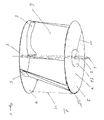
- FIG. 1 shows a perspective view of a rotor of the device according to the invention.
- the drivable by a flowing fluid 20 rotationally symmetric Rotor 1 is rotatably mounted about its axis of rotation 2 and by means of a in the FIG. 1 Coupling device 38, not shown, coupled to an electrical generator 39 for generating electrical energy.
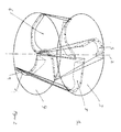
- the rotor 1 is designed as a flow-through rotor and has three rotor blades 6 arranged parallel to the rotation axis 2 and spaced therefrom, having a rotor blade length L RB and a rotor blade width B RB , and at least one first 3 and one arranged perpendicularly to the rotation axis 2 in a plane to parallel opposite second support member 4, wherein the rotor blades 6 extend between which support members 3, 4 and are held by these.
- the carrier elements 3, 4 in the form of disc-shaped blanks.
- the axis of rotation 2 of the rotor 11 is in a in the FIG. 9 schematically indicated bearings 28 rotatably mounted, wherein the bearing 28 by means of stub shaft 8, which is connected to the first 3 and the second 4 carrier element, preferably by means of in the FIG. 15
- Rotor shaft bottles 52, 53 are fixedly connected.
- each rotor blade 6 in its longitudinal direction, axially to the axis of rotation 2, a part-circular cylindrical trough-shaped curvature around a Wölbachse 10 which by a radial angle 12 of about 25 ° in the radial direction to the axis of rotation 2 and a tangential angle 13 of ca 25 ° in the circumferential direction of the rotation axis 2 is inclined.
- FIGS. 9A . 9B . 10 and 11 It can be seen that as a result of the inclined wölbachse 10 belonging to a rotor blade 6 abutting edges on the first 3 and the second 4 carrier element in the direction of rotation of the rotation axis 2 due to the tangential angle 13 in the axial direction of the rotor is not congruent but offset from each other.
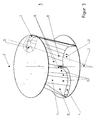
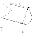
- FIGS. 1 to 3 Rotor shown in the direction of Wölbachse 10 a curved portion 11 with a radius r rbw 16, a tangentially extending first 14 and a tangent itself extending second guide portion 15, wherein the first guide portion 14 of the rotation axis 2 of the rotor 1 faces and the second guide portion 15 of the Au ⁇ enseite the rotor 1 faces.
- the width of the first guide section 14 in the region of the first carrier element 3 is smaller than its width in the region of the second carrier element 4 and the width of the second guide section 15 is greater in the region of the first carrier element 3 than in the region of the second carrier element 4th
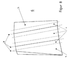
- FIG. 4 is the part-circular cylindrical bulge 11 in the form of a circular arc and in the FIG. 5 as a polygonal curve with in the FIG. 8 illustrated bending lines 18 executed.
- FIG. 16 is an alternative designed as a flow-through rotor 1 ', in which each rotor blade 6' in its longitudinal direction, axially to the axis of rotation 2 of the rotor 1 ', a partially circular camber 11' about a Wölbachse 10 ', which is arranged parallel to the direction of rotation axis 2 is such that the rotor blade 11 'in the radial direction corresponds to a circular arc.
- a polygonal design of the curvature 11' is possible.
- the rotor 1 ' has three in the axial direction of the axis of rotation 2 straight rotor blades 6' with an arc angle of the arc of about 60 °.
- the Indian FIG. 16 illustrated rotor has, for example, a diameter D R of about 2000 mm, wherein the radius 16 'of the partially circular camber is 900 mm.
- the rotor blades 6, 6' are each arranged at equal angles to one another. In rotors 1, 1 'with three rotor blades 6, 6', the angle between two adjacent rotor blades is 120 °.
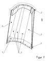
- FIGS. 1 . 2 . 3 . 6 . 7 are arranged on the rotor blades 6 in the region of the first 3 and / or the second 4 carrier element, in cross-section throat-like Thickenings 5, 17, which extend in the radial direction of the axis of rotation 2 of the rotor 1.
- the throat-like thickenings 5 17 fasteners 9 are arranged, in particular inserted inserts by means of which the rotor blades 6 are fixed to the support elements 3, 4.
- the throat-like thickening 5 is attached to the side 50 of the rotor blade 6 facing away from the flow direction.
- the flow of the rotor blades 6 can be influenced.
- rotor blade 6 are throat-like thickening 5, 17 attached both on its side facing the flow direction 51 and on its side facing away from the flow direction 50 side.
- the device has a fluid guide element 19 with a fluid inlet opening 21 facing the fluid flow 20 and a fluid outlet opening 22 facing the rotor 1, wherein the shape of the fluid guide element 19 causes the fluid flow 20 to be directed only to the leading, the flow direction facing sides 51 of the rotor blades 6 of the rotor 1, so that the returning, the flow direction facing away from sides 50 of the rotor blades 6 of the rotor 1 of the fluid flow 20 are not exposed.
- the effective for the flowing fluid cross-sectional area of the Fluidauslassö réelle 22 is considerably smaller than the fluid flow 20 exposed cross-sectional area of the fluid inlet opening 21, so that the flow rate of fluid flowing out of the Fluidauslassö réelle 22 compared to the flow rate of the fluid inlet opening 21 inflowing fluid 20 increases significantly is.
- the outlet opening 22 of the Fluidleitelements 19 is radially spaced from the axis of rotation 2 of the rotor 1 is arranged.
- the fluid guide element 19 is symmetrical funnel-shaped with respect to a parallel to the axis of rotation 2 of the rotor 1 arranged symmetry plane 47.
- the contour of the Fluidleitelements 19 facilitates a tangential flow with a low flow resistance and causes only a small turbulence.
- the fluid guiding element 19 is arranged offset laterally relative to the rotor 1, the fluid inlet opening 21 and the fluid outlet opening 22 of the fluid guiding element 19 being arranged laterally offset from the axis of rotation 2 of the rotor 1.
- the width B ALE of the cross-sectional area of the fluid outlet port 22 of the fluid guide 19 is 200 mm at a rotor diameter (D R ) 48 of 1200 mm and the width B ALE is 330 mm at a rotor diameter (D R ) 48 of 2000 mm Height H ALE of the cross-sectional area of the fluid outlet opening 22 of the Fluidleitelements 19 substantially corresponds to the axial length 49 of the rotor 1.
- the axis of rotation 2 of the rotor 1 is arranged at a right angle to the flow direction of the flowing fluid 20.
- the axis of rotation 2 of the rotor 1 is parallel to the vertical.
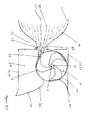
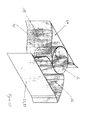
- the Figure 9A shows a rotor 1, which is arranged in a substantially cuboidal housing 25 having an inlet opening 26 and an outlet opening 27 for the flowing fluid 20, wherein the inlet opening 26 at the fluid flow 20 side facing the housing 25 and the outlet opening 27 at the first side opposite the second side of the housing 25 is arranged, which is arranged with respect to the fluid flow 20 downstream of the rotor 1.
- the bearing 28 of the rotor 1, in particular the at least one bearing for the rotor 1 is arranged.
- the housing 25 In the flow direction behind the rotor 1, the housing 25 in the region of the outlet opening 27 fluidically effective guide elements 29, 30, which facilitate an outflow of the fluid from the rotor 1 and the housing 25.
- the fluid guide 19 in the housing 25 between the inlet opening 26 of the housing 25 and the rotor first arranged which allows a compact design and is advantageous in terms of the assembly work at the installation.
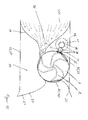
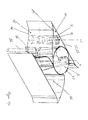
- FIG. 9B To adapt to individual installation locations and fluidic conditions of the fluid flow 20 is in the FIG. 9B illustrated embodiment in which the fluid guide 19 is disposed outside of the housing 25 and is connected only to the first side of the housing 25, in particular by means of a flange 31st
- guide elements in the area of the flange connection 31, can be installed in the form of venturi nozzles, so that the fluid flow flowing past the guide elements of the flange connection 31 travels with additional fluid and thereby increases the volume flow.
- the housing 25 is shown with a cylindrical arranged in the direction of the axis of rotation 2 recess 32 which extends to at least one frontal axial boundary surface 44, 45 of the housing 25, and is adapted to an electric generator 39 and / or other electrical components 46, for example, to accommodate the inverter dipping.
- the recess 32 is closed with a cover, not shown, sealing or hermetically sealed cover.
- the entire rotor 1 with the rotor blades 6 and the carrier elements 3, 4 is produced in one piece from a plastic reinforced with additives by means of a non-pressure casting process, so that a separate assembly of the rotor blades 6 on the carrier elements 3, 4 is omitted ,
- the rotor blades 6 and / or the carrier elements 3, 4 are produced individually from a plastic reinforced with additives by means of a non-pressure casting process, the rotor blades 6 being screwed or riveted to the carrier elements 3, 4.
- the rotor blades 6 and / or the carrier elements 3, 4 made of a metal, in particular a corrosion-resistant metal, in particular aluminum, aluminum alloy, stainless steel or a galvanized, ferrous metal, and / or have a shell of such a material , which is foamed for reinforcement.
- the rotor blades 6' consist of a preferably plate-shaped material, in particular of a metal, in which the partially cylindrical curvature 11 'is rolled.
- the rotor blades 6 ' are fastened to the carrier elements 3, 4 by means of welding. It lends itself to provide the support elements 3, 4 with grooves which have exactly the contour of the corresponding end face of the rotor blades 6 'with the arcuate shape of the leaf curvature 11', so that the end faces of the rotor blades 6 'are guided in the grooves, which facilitates the exact positioning of the rotor blades 6 'during their assembly.
- At least parts of the Fluidleitelements 19 made of a plastic, in particular a plastic reinforced with additives, or have a shell of a deformed plate-shaped metal, in particular from a sheet containing aluminum, wherein the shell is filled with a polymer foam.
- parts of the housing 25 are made of a plastic reinforced with additives or have a shell 33 of a plate-shaped metal, in particular of a sheet containing aluminum, wherein the shell is filled with a polymer foam.
- polyamide PA 12 G which is marketed by the company Handtmann is used with the trade name lauramide ® as plastic.
- This plastic is reinforced depending on the desired strength with fibers or shavings of metal, polymers, carbon or ceramic.
- the support member 3 of the rotor 1 on a rotationally symmetrical to the rotational axis peripheral surface on a tooth contour 35, which is connected to a further gear 42 of a coupling device 38 for driving a electrical generator 39 is in operative connection, wherein the tooth contour 35 is integrally formed on the at least one support element 3.
- the tooth contour 35 is a separate part, in particular a sprocket or a plurality of tooth segments, which is connected to the at least one support element 3.
- FIG. 11 and 12 An example of a system for converting the flow energy of a flowing gaseous fluid into electrical energy is shown, in which the rotor 1 driven by the flowing fluid is mechanically coupled by means of a coupling device 38 to an electric generator 39 having a rotatable drive shaft 43.
- the coupling device 38 is formed as a gear transmission having at least a first gear 40 and a second gear 41, wherein the first gear 40 is disposed on the support member 3 of the rotor 1 or is formed by the tooth contour 35 of the support member 3 and the second gear 41 is disposed on the drive shaft 43 of the generator 39.
- the coupling device 38 for adjusting the rotational speed of the rotor 1 to the rated speed of the generator 39 further gears 42.
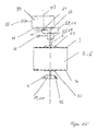
- FIG. 15 2 shows by way of example a part of a coupling device 38 in the form of a geared bearing 57 with a rotor bearing 28 designed as a ball bearing 55, in particular a tapered roller bearing, the ball bearing 55 being a bearing housing 59, the ball bearing 54 being a bearing housing 60 and the toothed shafts and / or gears of the toothed gear mechanism 57 are received by a transmission housing 58.
- the axis of rotation 2 of the rotor 1, 1 'aligned with the input-side drive axle 62 of the gear transmission 57, while the output-side output shaft 61 of the gear transmission 57 arranged offset thereto is.
- the drive shaft 43 of the generator 39 which is provided with a gear 41, dips into the housing 58 of the gear mechanism and is driven by a gear arranged on the output shaft 61 of the gear mechanism 57.
- the reference numeral 58 represents schematically indicated mechanical connections to structural parts of the housing 25, for absorbing the forces.
- the gears 40, 41, 42, the tooth contour 35 and the gears and / or toothed shafts of the gear transmission 57 are designed in the embodiment as spur or helical gears.
- the drive shaft 43 of the generator 39 is arranged in the direction of the axis of rotation 2 of the rotor 1, the generator 39 being arranged in a recess 32 in the housing 25.
- the generator 39 is arranged on one of the front side of the rotor 1 opposite end face 44, 45 of the housing 25.
- required electrical components 46 such as inverter and control arranged.
- FIGS. 9A . 9B and 13 The in the FIGS. 9A . 9B and 13 The system is set up in a fixed direction with respect to the flow direction of the flowing fluid 20.
- the system comprises a pendulum bearing on a pedestal or mast, in which the system is rotatable about the vertical in the horizontal direction in order to adapt to the direction of fluid flow.
- the axis of rotation of the pendulum axis 36 is arranged in the flow direction in front of the axis of rotation 2 of the rotor 1, so that the system itself is in the wind.
- the pendulum axis 36 about which the system is rotatable about the vertical in the horizontal direction, a shaft, in particular a solid or hollow shaft, the extending over the vertical extent of the housing 25 between the end faces 44, 45, preferably in the plane of symmetry 24 of the air guide.
- the shaft section arranged in the flow region 20 of the fluid is lined with an aerodynamically effective cladding 37.
- the diameter of the rotor is 1200 mm, the diameter of the recess 450 mm, the width of the inlet opening of the Fluidleitelements and the housing 2000 mm, the width of the Fluidauslassö réelle the Fluidleitelements 200 mm, wherein the axis of rotation of the rotor from the inlet opening of the Fluidleitelements 1785 mm apart. Furthermore, the axis of rotation of the rotor is 950 mm downstream of the pendulum axis.
- the diameter of the rotor is 2000 mm, the diameter of the recess 800 mm, the width of the inlet opening of the Fluidleitelements and the housing 3200 mm, the width of the fluid outlet of the Fluidleitelements 330 mm, wherein the axis of rotation of the rotor of the inlet opening of the Fluidleitelements 2975 mm apart. Furthermore, the axis of rotation of the rotor is 1590 mm downstream of the pendulum axis.
- FIGS. 1 to 14 Describe an embodiment of the invention with reference to the rotor 1 with inclined to the axis of rotation rotor blades 6. All advantageous developments of the device with the rotor 1 and the system equipped therewith also apply to the rotor 1 'with rotor blades 6', the creep 10 'parallel to the direction of Rotary axis 2 are arranged so that it is not carried out separately to avoid unnecessary repetition.
Landscapes
- Engineering & Computer Science (AREA)
- Life Sciences & Earth Sciences (AREA)
- Sustainable Development (AREA)
- Sustainable Energy (AREA)
- Chemical & Material Sciences (AREA)
- Combustion & Propulsion (AREA)
- Mechanical Engineering (AREA)
- General Engineering & Computer Science (AREA)
- Power Engineering (AREA)
- Wind Motors (AREA)
- Connection Of Motors, Electrical Generators, Mechanical Devices, And The Like (AREA)
Applications Claiming Priority (1)
| Application Number | Priority Date | Filing Date | Title |
|---|---|---|---|
| DE202010003361U DE202010003361U1 (de) | 2010-03-09 | 2010-03-09 | Vorrichtung zur Umwandlung von Strömungsenergie eines strömenden gasförmigen Fluids in Rotationsenergie und Anlage zur Erzeugung von elektrischer Energie damit |
Publications (2)
| Publication Number | Publication Date |
|---|---|
| EP2365213A2 true EP2365213A2 (fr) | 2011-09-14 |
| EP2365213A3 EP2365213A3 (fr) | 2013-07-31 |
Family
ID=42558321
Family Applications (1)
| Application Number | Title | Priority Date | Filing Date |
|---|---|---|---|
| EP11157278.0A Withdrawn EP2365213A3 (fr) | 2010-03-09 | 2011-03-08 | Dispositif de transformation d'énergie d'écoulement en énergie de rotation |
Country Status (2)
| Country | Link |
|---|---|
| EP (1) | EP2365213A3 (fr) |
| DE (1) | DE202010003361U1 (fr) |
Cited By (1)
| Publication number | Priority date | Publication date | Assignee | Title |
|---|---|---|---|---|
| US20230021639A1 (en) * | 2021-07-23 | 2023-01-26 | Neville Patel | Wind turbine system |
Families Citing this family (5)
| Publication number | Priority date | Publication date | Assignee | Title |
|---|---|---|---|---|
| EP3126667A1 (fr) | 2014-04-03 | 2017-02-08 | Cassius Advisors GmbH | Rotor et turbine à fluide avec rotor |
| US9982655B2 (en) | 2014-04-03 | 2018-05-29 | Windtree Gmbh | Rotor and fluid turbine with rotor |
| US9863394B2 (en) | 2014-04-03 | 2018-01-09 | Cassius Advisiors Gmbh | Fluid turbine |
| US9739153B2 (en) | 2014-04-03 | 2017-08-22 | Cassius Advisors Gmbh | Rotor and fluid turbine with rotor |
| DE102020124612A1 (de) | 2020-09-22 | 2022-03-24 | NRGSync Holding GmbH | Vorrichtung zur Erzeugung elektrischer Energie |
Family Cites Families (4)
| Publication number | Priority date | Publication date | Assignee | Title |
|---|---|---|---|---|
| US6158953A (en) * | 1998-12-04 | 2000-12-12 | Lamont; John S | Wind turbine with variable position blades |
| WO2007064155A1 (fr) * | 2005-11-30 | 2007-06-07 | Geumpoong Energy | Aerogenerateur |
| US7948110B2 (en) * | 2007-02-13 | 2011-05-24 | Ken Morgan | Wind-driven electricity generation device with Savonius rotor |
| DE102008036307A1 (de) * | 2007-08-10 | 2009-05-07 | Krauss, Gunter | Strömungsenergieanlage |
-
2010
- 2010-03-09 DE DE202010003361U patent/DE202010003361U1/de not_active Expired - Lifetime
-
2011
- 2011-03-08 EP EP11157278.0A patent/EP2365213A3/fr not_active Withdrawn
Non-Patent Citations (1)
| Title |
|---|
| None |
Cited By (2)
| Publication number | Priority date | Publication date | Assignee | Title |
|---|---|---|---|---|
| US20230021639A1 (en) * | 2021-07-23 | 2023-01-26 | Neville Patel | Wind turbine system |
| US11746745B2 (en) * | 2021-07-23 | 2023-09-05 | Neville Patel | Sidewall wind turbine system with plurality of wind directors |
Also Published As
| Publication number | Publication date |
|---|---|
| DE202010003361U1 (de) | 2010-08-12 |
| EP2365213A3 (fr) | 2013-07-31 |
Similar Documents
| Publication | Publication Date | Title |
|---|---|---|
| EP2365213A2 (fr) | Dispositif de transformation d'énergie d'écoulement en énergie de rotation | |
| EP1002949A2 (fr) | Eolienne à axe vertical | |
| EP1916415B1 (fr) | Eolienne et procédé pour la production d'électricité de l'air environnant mobile | |
| DE2851406B2 (de) | Windturbine | |
| EP2807369B1 (fr) | L'eolienne a l'effet venturi | |
| CH687637A5 (de) | Axialkleinventilator. | |
| DE102009038076A1 (de) | Rotorelement zur Umströmung durch ein Fluid und Rotor | |
| EP0811764A1 (fr) | Combinaison réducteur-générateur pour eolienne | |
| WO2019076514A1 (fr) | Installation à énergie d'écoulement, notamment turbine éolienne à enveloppe | |
| EP2128432B1 (fr) | Eolienne avec une entrée d'air axiale et une sortie d'air radiale | |
| DE112017004377B4 (de) | Windturbinenanlage | |
| DE3028606A1 (de) | Zum einbau in rohrleitungen, kanaele oder kanalaehnliche gehaeuse bzw. in lueftungs- und klimageraete bestimmte ventilatoreinheit | |
| EP2236816A2 (fr) | Petite éolienne | |
| DE202010003360U1 (de) | Vorrichtung zur Umwandlung von Strömungsenergie eines strömenden gasförmigen Fluids in Rotationsenergie und Anlage zur Erzeugung von elektrischer Energie damit | |
| DE102011113280B4 (de) | Rotor zur Umwandlung von Strömungsenergie eines strömenden gasförmigen Fluids in Rotationsenergie und Anlage zur Erzeugung elektrischer Energie damit | |
| US10895242B2 (en) | Output reinforcement device of power generator and natural energy type power generator | |
| EP2546513A2 (fr) | Eolienne et roue de turbine associée | |
| EP2636892A2 (fr) | Installation éolienne et procédé de production d'énergie rotative par le vent | |
| DE102012017863A1 (de) | Rotor zur Umwandlung von Strömungsenergie eines strömenden gasförmigen Fluids in Rotationsenergie und Anlage zur Erzeugung von elektrischer Energie damit | |
| AT510210B1 (de) | Vorrichtung zur umsetzung der energie eines strömenden mediums | |
| EP1507973B1 (fr) | Turbine eolienne a gaine | |
| DE4202649A1 (de) | Windkonverter, insbesondere fuer windschwache gebiete | |
| DE102012017861A1 (de) | Verfahren zum Herstellen von Komponenten eines Rotors, Verwendung der mit dem Verfahren hergestellten Komponenten für einen Rotor einer Windkraftanlage und eine mit dem Rotor ausgestattete Windkraftanlage | |
| WO2006050711A1 (fr) | Rotor pour convertir des ecoulements libres dans des dispositifs d'ecoulement | |
| DE102009022537A1 (de) | Windenergieanlage mit offener Gondelbauweise |
Legal Events
| Date | Code | Title | Description |
|---|---|---|---|
| PUAI | Public reference made under article 153(3) epc to a published international application that has entered the european phase |
Free format text: ORIGINAL CODE: 0009012 |
|
| AK | Designated contracting states |
Kind code of ref document: A2 Designated state(s): AL AT BE BG CH CY CZ DE DK EE ES FI FR GB GR HR HU IE IS IT LI LT LU LV MC MK MT NL NO PL PT RO RS SE SI SK SM TR |
|
| AX | Request for extension of the european patent |
Extension state: BA ME |
|
| PUAL | Search report despatched |
Free format text: ORIGINAL CODE: 0009013 |
|
| AK | Designated contracting states |
Kind code of ref document: A3 Designated state(s): AL AT BE BG CH CY CZ DE DK EE ES FI FR GB GR HR HU IE IS IT LI LT LU LV MC MK MT NL NO PL PT RO RS SE SI SK SM TR |
|
| AX | Request for extension of the european patent |
Extension state: BA ME |
|
| RIC1 | Information provided on ipc code assigned before grant |
Ipc: F03D 3/04 20060101AFI20130625BHEP Ipc: F03D 3/06 20060101ALI20130625BHEP |
|
| STAA | Information on the status of an ep patent application or granted ep patent |
Free format text: STATUS: THE APPLICATION IS DEEMED TO BE WITHDRAWN |
|
| 18D | Application deemed to be withdrawn |
Effective date: 20140201 |