EP2365733A1 - Four à micro-ondes - Google Patents
Four à micro-ondes Download PDFInfo
- Publication number
- EP2365733A1 EP2365733A1 EP10745925A EP10745925A EP2365733A1 EP 2365733 A1 EP2365733 A1 EP 2365733A1 EP 10745925 A EP10745925 A EP 10745925A EP 10745925 A EP10745925 A EP 10745925A EP 2365733 A1 EP2365733 A1 EP 2365733A1
- Authority
- EP
- European Patent Office
- Prior art keywords
- magnetron
- temperature
- detection device
- temperature detection
- microwave oven
- Prior art date
- Legal status (The legal status is an assumption and is not a legal conclusion. Google has not performed a legal analysis and makes no representation as to the accuracy of the status listed.)
- Granted
Links
Images


Classifications
-
- H—ELECTRICITY
- H05—ELECTRIC TECHNIQUES NOT OTHERWISE PROVIDED FOR
- H05B—ELECTRIC HEATING; ELECTRIC LIGHT SOURCES NOT OTHERWISE PROVIDED FOR; CIRCUIT ARRANGEMENTS FOR ELECTRIC LIGHT SOURCES, IN GENERAL
- H05B6/00—Heating by electric, magnetic or electromagnetic fields
- H05B6/64—Heating using microwaves
- H05B6/66—Circuits
- H05B6/666—Safety circuits
-
- H—ELECTRICITY
- H05—ELECTRIC TECHNIQUES NOT OTHERWISE PROVIDED FOR
- H05B—ELECTRIC HEATING; ELECTRIC LIGHT SOURCES NOT OTHERWISE PROVIDED FOR; CIRCUIT ARRANGEMENTS FOR ELECTRIC LIGHT SOURCES, IN GENERAL
- H05B6/00—Heating by electric, magnetic or electromagnetic fields
- H05B6/64—Heating using microwaves
- H05B6/642—Cooling of the microwave components and related air circulation systems
Definitions
- the present invention relates to a microwave oven that heats a heating object through high frequency supplied from a magnetron or the like.
- a microwave oven which includes a temperature detection device inside an air guide as a passage through which an exhaust air stream flows in order to detect the temperature of the exhaust air stream of the magnetron, where the temperature detection device is provided for the purpose of preventing damage to the apparatus caused by abnormal heat generated from the magnetron when the apparatus is operated while there is no heating object inside a heating chamber (for example, refer to PTL 1).
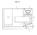
- Fig. 6 is a plan cross-sectional view illustrating a configuration of a conventional microwave oven. Fig. 6 illustrates a configuration in which a temperature detection device is attached to an air guide of the conventional microwave oven. As shown in Fig.
- the microwave oven includes: heating chamber 1 accommodating a heating object; magnetron 2 supplying high frequency to heating chamber 1; cooling device 3 supplying a cooling air to heating chamber 1 and magnetron 2; air guide 4 guiding a cooling air used to cool magnetron 2 toward heating chamber 1; and temperature detection device 5 provided inside air guide 4 and detecting the temperature of a cooling air.
- magnetron 2 includes an anode to which power is supplied and a cooling fin which is disposed inside an air stream path of the cooling air.
- the temperature of abnormal heat generated from magnetron 2 is transferred from the anode to the cooling fin, the cooling air flowing around the cooling fin is heated, and the temperature of the heated exhaust air stream is detected by temperature detection device 5. For this reason, there are problems that it takes time to thermally transfer the temperature of the abnormal heat to temperature detection device 5 and an abrupt increasing temperature may not be detected.
- the present invention is made to solve the above-described problems, and provides a microwave oven that improves the precision of the detection precision when a user operates the microwave oven in a no-load state by mistake, prevents damage of the apparatus, and has high safety and reliability.
- a microwave oven of the present invention includes: a heating chamber for accommodating a heating object; a magnetron for heating the heating object accommodated in the heating chamber; a blower for cooling the magnetron; a temperature detection device for detecting a temperature of the magnetron; and a control device for controlling an output power of the magnetron on the basis of temperature information output from the temperature detection device, wherein the temperature detection device is disposed inside a cooling fin of the magnetron and the control device controls the magnetron on the basis of the temperature information obtained before cooking is started.
- the temperature of the abnormal heat generated from the magnetron may be directly transferred from the anode to the temperature detection device via the cooling fin, and the heat may be highly efficiently transferred by reducing a temperature transfer loss. Also, since the abnormality detection control is performed on the basis of the temperature information obtained before the cooking is started, the erroneous detection due to repeated heating may be prevented.
- a microwave oven may be provided which improves the precision of the detection of abnormality in a no-load operation state, prevents the damage of the apparatus, and has high safety and reliability.
- Fig. 1 is a diagram illustrating an external shape of a microwave oven of the embodiment of the present invention
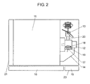
- Fig. 2 is a cross-sectional view illustrating the microwave oven when seen from the top surface thereof.
- the microwave oven of the embodiment includes: heating chamber 11 accommodating a heating object; magnetron 12 generating high frequency; blower 13 cooling magnetron 12; air guide 14 guiding a cooling air used to cool magnetron 12 toward heating chamber 11; operation unit 15 equipped with control device 23; door 16 opening and closing an opening of heating chamber 11; and exterior frame 21.
- temperature detection device 17 detecting the temperature of magnetron 12 is inserted and fixed to contact cooling fin 19 at a position adjacent to anode 18 of magnetron 12 between the outflow side of cooling air 20 from blower 13 and cooling fin 19. Further, temperature detection device 17 is disposed at the lower air stream side of anode 18 where cooling air 20 generated from blower 13 is not directly blown, and may detect the temperature of magnetron 12 without the influence of cooling air 20.
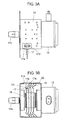
- Figs. 3A and 3B are plan and front views respectively illustrating an attachment portion of temperature detection device 17 of the microwave oven of the embodiment. That is, Fig. 3B is a view when seen from the front surface side (the side of operation unit 15) of heating chamber 11.
- magnetron 12 includes antenna 12a that emits radio waves toward heating chamber 11 via anode 18.
- Plural thin-sheet-shaped cooling fins 19 are disposed around anode 18 at a predetermined interval. Each cooling fin 19 is fixed to the inner peripheral wall of frame 22 surrounding anode 18.
- Temperature detection device 17 is caulk-fixed to attachment hole 17c that is formed at one-side piece portion 17b of attachment plate 17a obtained by bending a T-shaped sheet piece in an L-shape.
- the other-side piece portion 17d of attachment plate 17a is screw-fixed to the top surface of frame 22.
- attachment plate 17a and air guide 14 are simultaneously fixed to frame 22 by a screw or the like via screw hole 14a formed in air guide 14 shown in Fig. 1 .
- temperature detection device 17 contacts cooling fin 19. Further, in the embodiment, used is temperature detection device 17 has a configuration in which a temperature detection element such as a thermistor is enclosed in a metallic casing, but the present invention is not particularly limited to the configuration.
- temperature detection device 17 is installed by using a gap at the end portion around the reinforcement portion of cooling fin 19. Accordingly, when temperature detection device 17 is inserted between thin-sheet-shaped cooling fins 19, cooling fin 19 is not deformed. Further, since the temperature detection device is installed inside cooling fin 19 and is fixed to attachment plate 17a attached to frame 22, the temperature of magnetron 12 may be detected with high precision. The detection precision may be further improved when temperature detection device 17 is installed to contact cooling fin 19.
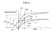
- Fig. 4 is a diagram illustrating an example of a relationship between a temperature detected by temperature detection device 17 of the microwave oven of the embodiment having the above-described configuration and time.
- Radio waves supplied from magnetron 12 are guided toward heating chamber 11 in a condition without a load such as food. However, since there is no food absorbing radio waves, the radio waves are reflected from heating chamber 11 and are returned to magnetron 12, so that the temperature of anode 18 increases. A difference in temperature between the curves A and C may be different in accordance with the type or the amount of food, but generally the temperature of the curve C increases when there is no load.
- the temperature of magnetron 12 is high. Also, when there is a heating object such as food in heating chamber 11, the temperature increases like the curve B of the graph in Fig. 4 .
- a threshold value is set on the basis of temperature information of temperature detection device 17 before cooking is started, and it is determined that the repeated operations are performed when the current temperature is the threshold temperature or more.
- ⁇ Td when there is no load after the repeated operations
- ⁇ Tb the increasing temperature value
- FIG. 5 is a flowchart illustrating a control of the microwave oven of the embodiment.
- control device 23 confirms whether the current temperature is a predetermined temperature or more on the basis of the temperature information of temperature detection device 17 immediately after the start of the control, and determines whether the repeated operations are performed (it is determined whether it is a repeated operation state S12 or a normal state S11 at the timing t0 of Fig. 4 ).
- the current temperature is a predetermined temperature or more (S12 of Fig. 4 )
- it is determined that the repeated operations are performed YES of step S1
- the current process proceeds to step S2.
- the current temperature is not a predetermined temperature or more, it is determined that the repeated operations are not performed (NO of step S1), and the current process proceeds to step S5.
- step S2 the process of step S2 is repeated until a predetermined time interval (the timings t0 to t1 of Fig. 4 ) is elapsed (NO of step S2).
- a predetermined time is elapsed (YES of step S2)
- the current process proceeds to step S3, and it is determined whether the current temperature is a predetermined temperature or more on the basis of the temperature information of temperature detection device 17 (it is determined whether it is a no-load state S122 or a load state S121 at the timing t1 of Fig. 4 ).
- it is the load state S121 where the current temperature is not a predetermined temperature or more (NO of step S3) it is determined that the magnetron is normally operated, and the current process proceeds to step S8.
- step S3 when it is a no-load state S122 where the current temperature is a predetermined temperature or more (YES of step S3), it is determined that a no-load operation is performed, and the current process proceeds to step S4. Then, the output reduction process of magnetron 12 is performed, and a detection flag is set in order to prevent damage of the apparatus and inform an abnormal operation.
- step S8 the process of step S8 is repeated until it is determined that the cooking is finished (NO of step S8).
- the current process proceeds to step S9, and it is determined whether the detection flag is set.
- the detection flag is not set (NO of step S9)
- the current process proceeds to END.
- the detection flag is set (YES of step S9)
- the current process proceeds to step S10, an error display informing the abnormal operation during cooking is generated, and the current process proceeds to END.
- the error display informs a customer that the cooking is not normally finished since the output reduction process is performed due to, for example, the abnormality detection. Further, the error display calls attention so that the cooking is not performed without any load by informing the no-load operation. When the history of the error display is stored, this information may be usefully used to guess the reason of failure during a service.
- step S6 it is determined whether it is the no-load state S112 or the load state S111 at the timing t1 of Fig. 4 .
- the step may be created so that a program may not be easily made with a determination reference. Further, the determination procedure may be made in sequence or may not be needed. Further, the method of determining a condition or the method of determining whether a current value is a predetermined value or more or a predetermined value or less may be freely used in combination to match the use method.
- the abnormal temperature caused by the heating of magnetron 12 is directly transferred from anode 18 to temperature detection device 17 via cooling fin 19, and the heat may be highly efficiently transferred by reducing a temperature transfer loss.
- the abnormality detection control may be performed on the basis of the temperature information before the cooking is started. In this manner, the erroneous detection due to the repeated heating may be prevented, the safety may be ensured, and the damage of the apparatus may be prevented.
- temperature detection device 17 is disposed at the lower air stream side of anode 18 of magnetron 12 on the opposite side of blower 13 blowing cooling air 20. As a result, the cooling air generated from blower 13 is not directly blown to temperature detection device 17, so that the amount of heat generated from magnetron 12 may be more precisely detected.
- the present invention has a configuration in which a microwave oven includes: a heating chamber for accommodating a heating object; a magnetron for heating the heating object accommodated in the heating chamber; a blower for cooling the magnetron; a temperature detection device for detecting a temperature of the magnetron; and a control device for controlling an output power of the magnetron on the basis of temperature information output from the temperature detection device, wherein the temperature detection device is disposed inside a cooling fin of the magnetron and the control device controls the magnetron on the basis of the temperature information obtained before cooking is started.
- the temperature of the abnormal heat generated from the magnetron may be directly transferred from the anode to the temperature detection device via the cooling fin, and the heat may be highly efficiently transferred by reducing a temperature transfer loss. Also, since the abnormality detection control is performed on the basis of the temperature information obtained before the cooking is started, the erroneous detection due to repeated heating may be prevented.
- the present invention has a configuration in which the temperature detection device is disposed at a lower air stream side of an anode of the magnetron on the opposite side of the blower blowing cooling air toward the magnetron. Accordingly, the cooling air generated from the blower may not be directly blown to the temperature detection device, and the amount of the heat generated from the magnetron may be more precisely detected.
- the present invention has a configuration in which the control device detects abnormality on the basis of a value of temperature increase detected by the temperature detection device in a predetermined time interval. Accordingly, the erroneous detection may be prevented in the condition where the temperature of the magnetron is high due to the repeated heating, and the detection precision may be improved by separately setting the increasing temperature value when the temperature of the magnetron is low.
- the present invention improves the precision of the detection of abnormality in a no-load operation state, prevents the damage of the apparatus, and has high safety and reliability, the present invention may be applied to various microwave ovens.
Landscapes
- Physics & Mathematics (AREA)
- Electromagnetism (AREA)
- Electric Ovens (AREA)
- Control Of High-Frequency Heating Circuits (AREA)
Applications Claiming Priority (2)
| Application Number | Priority Date | Filing Date | Title |
|---|---|---|---|
| JP2009040798A JP2010196940A (ja) | 2009-02-24 | 2009-02-24 | 高周波加熱装置 |
| PCT/JP2010/000963 WO2010098038A1 (fr) | 2009-02-24 | 2010-02-17 | Four à micro-ondes |
Publications (3)
| Publication Number | Publication Date |
|---|---|
| EP2365733A1 true EP2365733A1 (fr) | 2011-09-14 |
| EP2365733A4 EP2365733A4 (fr) | 2014-01-22 |
| EP2365733B1 EP2365733B1 (fr) | 2014-12-31 |
Family
ID=42665255
Family Applications (1)
| Application Number | Title | Priority Date | Filing Date |
|---|---|---|---|
| EP10745925.7A Not-in-force EP2365733B1 (fr) | 2009-02-24 | 2010-02-17 | Four à micro-ondes |
Country Status (5)
| Country | Link |
|---|---|
| US (1) | US10076004B2 (fr) |
| EP (1) | EP2365733B1 (fr) |
| JP (1) | JP2010196940A (fr) |
| CN (1) | CN102318439B (fr) |
| WO (1) | WO2010098038A1 (fr) |
Cited By (3)
| Publication number | Priority date | Publication date | Assignee | Title |
|---|---|---|---|---|
| US20120152937A1 (en) * | 2010-12-21 | 2012-06-21 | Whirlpool Corporation | Methods of controlling cooling in a microwave heating apparatus and apparatus thereof |
| EP2993961A1 (fr) * | 2014-09-02 | 2016-03-09 | Miele & Cie. KG | Appareil de cuisson et procede |
| WO2021078867A1 (fr) * | 2019-10-23 | 2021-04-29 | Elekta Limited | Surveillance de l'état d'un magnétron |
Families Citing this family (4)
| Publication number | Priority date | Publication date | Assignee | Title |
|---|---|---|---|---|
| KR102482671B1 (ko) * | 2014-07-07 | 2022-12-29 | 노드슨 코포레이션 | Uv 시스템에서 rf 소스의 적합성을 판정하기 위한 시스템 및 방법 |
| JP6277086B2 (ja) * | 2014-08-25 | 2018-02-07 | 日立アプライアンス株式会社 | 高周波加熱装置 |
| US9991083B2 (en) * | 2016-02-23 | 2018-06-05 | Samsung Electrnoics Co., Ltd. | Magnetron cooling fin and magnetron having the same |
| CN110934485A (zh) * | 2018-09-25 | 2020-03-31 | 浙江绍兴苏泊尔生活电器有限公司 | 烹饪器具的控制方法及装置 |
Family Cites Families (15)
| Publication number | Priority date | Publication date | Assignee | Title |
|---|---|---|---|---|
| JPS5640029A (en) * | 1979-09-07 | 1981-04-16 | Matsushita Electric Ind Co Ltd | Method and apparatus for controlling food heating |
| US5507927A (en) * | 1989-09-07 | 1996-04-16 | Emery Microwave Management Inc. | Method and apparatus for the controlled reduction of organic material |
| US5022756A (en) * | 1989-11-03 | 1991-06-11 | Hewlett-Packard Company | Method and apparatus for spectrochemical analysis having maximum repeatability |
| JPH04121991A (ja) * | 1990-09-11 | 1992-04-22 | Matsushita Electric Ind Co Ltd | 高周波加熱装置 |
| JPH05280744A (ja) * | 1992-03-31 | 1993-10-26 | Toshiba Corp | 加熱調理器 |
| JPH06185738A (ja) | 1992-12-18 | 1994-07-08 | Sharp Corp | 加熱機器 |
| FR2759238B1 (fr) | 1997-01-31 | 1999-03-05 | Moulinex Sa | Dispositif de mesure de la temperature d'un magnetron pour four a micro-ondes |
| JPH10270162A (ja) * | 1997-03-24 | 1998-10-09 | Mitsubishi Electric Corp | 高周波加熱装置 |
| US5897807A (en) * | 1997-09-08 | 1999-04-27 | Amana Company, L.P. | Rethermalization pass through oven system |
| JP2002260841A (ja) * | 2001-02-28 | 2002-09-13 | Matsushita Electric Ind Co Ltd | 高周波加熱装置 |
| JP2004095501A (ja) * | 2002-09-04 | 2004-03-25 | Matsushita Electric Ind Co Ltd | 高周波加熱装置 |
| JP4099586B2 (ja) | 2003-12-10 | 2008-06-11 | 松下電器産業株式会社 | 誘導加熱調理器 |
| JP2005203211A (ja) | 2004-01-15 | 2005-07-28 | Mitsubishi Electric Corp | 電気加熱調理器 |
| JP2005241128A (ja) * | 2004-02-26 | 2005-09-08 | Sanyo Electric Co Ltd | 調理器 |
| JP4660568B2 (ja) | 2008-03-21 | 2011-03-30 | 株式会社東芝 | 加熱調理器 |
-
2009
- 2009-02-24 JP JP2009040798A patent/JP2010196940A/ja active Pending
-
2010
- 2010-02-17 WO PCT/JP2010/000963 patent/WO2010098038A1/fr not_active Ceased
- 2010-02-17 US US13/147,539 patent/US10076004B2/en active Active
- 2010-02-17 EP EP10745925.7A patent/EP2365733B1/fr not_active Not-in-force
- 2010-02-17 CN CN2010800076354A patent/CN102318439B/zh not_active Expired - Fee Related
Cited By (8)
| Publication number | Priority date | Publication date | Assignee | Title |
|---|---|---|---|---|
| US20120152937A1 (en) * | 2010-12-21 | 2012-06-21 | Whirlpool Corporation | Methods of controlling cooling in a microwave heating apparatus and apparatus thereof |
| EP2469974A1 (fr) * | 2010-12-21 | 2012-06-27 | Whirlpool Corporation | Procédés pour la commande du refroidissement d'un appareil de chauffage par micro-ondes et appareil correspondant |
| US9131541B2 (en) * | 2010-12-21 | 2015-09-08 | Whirlpool Corporation | Methods of controlling cooling in a microwave heating apparatus and apparatus thereof |
| US10064247B2 (en) | 2010-12-21 | 2018-08-28 | Whirlpool Corporation | Methods of controlling cooling in a microwave heating apparatus and apparatus thereof |
| US10912161B2 (en) * | 2010-12-21 | 2021-02-02 | Whirlpool Corporation | Methods of controlling cooling in a microwave heating apparatus and apparatus thereof |
| US11818826B2 (en) | 2010-12-21 | 2023-11-14 | Whirlpool Corporation | Methods of controlling cooling in a microwave heating apparatus and apparatus thereof |
| EP2993961A1 (fr) * | 2014-09-02 | 2016-03-09 | Miele & Cie. KG | Appareil de cuisson et procede |
| WO2021078867A1 (fr) * | 2019-10-23 | 2021-04-29 | Elekta Limited | Surveillance de l'état d'un magnétron |
Also Published As
| Publication number | Publication date |
|---|---|
| CN102318439A (zh) | 2012-01-11 |
| EP2365733B1 (fr) | 2014-12-31 |
| JP2010196940A (ja) | 2010-09-09 |
| EP2365733A4 (fr) | 2014-01-22 |
| US10076004B2 (en) | 2018-09-11 |
| WO2010098038A1 (fr) | 2010-09-02 |
| US20110284528A1 (en) | 2011-11-24 |
| CN102318439B (zh) | 2013-10-02 |
Similar Documents
| Publication | Publication Date | Title |
|---|---|---|
| EP2365733A1 (fr) | Four à micro-ondes | |
| KR20180059540A (ko) | 히터 수명 및 성능을 향상시키기 위한 통합 장치 및 방법 | |
| US11965655B2 (en) | Cooking appliance and control method thereof | |
| US11873995B2 (en) | Cooking appliance and method for controlling the same | |
| EP4656954A2 (fr) | Procédé de commande d'appareil de cuisson et appareil de cuisson | |
| EP2378204B1 (fr) | Équipement de chauffage haute fréquence | |
| KR102226552B1 (ko) | 차량용 복사열 히터의 안전 제어 방법 | |
| JP2011149607A (ja) | 加熱調理器 | |
| JP5590987B2 (ja) | 誘導加熱調理器 | |
| JP4123366B2 (ja) | 誘導加熱調理器 | |
| KR20010039530A (ko) | 쿠킹 히터장치 | |
| EP2287532A1 (fr) | Appareil de chauffage haute fréquence avec dispositif de chauffage électrothermique | |
| EP2568768B1 (fr) | Four à micro-ondes | |
| JP5246293B2 (ja) | 加熱調理器 | |
| KR100199140B1 (ko) | 다기능 전자렌지의 조리실 온도에 따른 제어방법 | |
| US20070045278A1 (en) | Glass ceramic cooktop having at least one burner | |
| JP4309370B2 (ja) | 電気ヒーターの空焼き防止装置 | |
| JP2024019847A (ja) | 加熱調理器 | |
| JPH04324278A (ja) | 高周波加熱装置 | |
| KR20130023859A (ko) | 오븐 제어장치의 과열 방지 시스템 및 과열 방지 방법 | |
| JP2000223251A (ja) | 電磁誘導加熱調理器 | |
| JPS6364869B2 (fr) | ||
| JPS60218794A (ja) | オ−ブンレンジの制御装置 | |
| JPH0564614U (ja) | 電子レンジにおける冷却ファンモータの故障検出装置 |
Legal Events
| Date | Code | Title | Description |
|---|---|---|---|
| PUAI | Public reference made under article 153(3) epc to a published international application that has entered the european phase |
Free format text: ORIGINAL CODE: 0009012 |
|
| 17P | Request for examination filed |
Effective date: 20110603 |
|
| AK | Designated contracting states |
Kind code of ref document: A1 Designated state(s): AT BE BG CH CY CZ DE DK EE ES FI FR GB GR HR HU IE IS IT LI LT LU LV MC MK MT NL NO PL PT RO SE SI SK SM TR |
|
| DAX | Request for extension of the european patent (deleted) | ||
| A4 | Supplementary search report drawn up and despatched |
Effective date: 20140102 |
|
| RIC1 | Information provided on ipc code assigned before grant |
Ipc: H05B 6/68 20060101AFI20131217BHEP |
|
| GRAP | Despatch of communication of intention to grant a patent |
Free format text: ORIGINAL CODE: EPIDOSNIGR1 |
|
| INTG | Intention to grant announced |
Effective date: 20140722 |
|
| GRAS | Grant fee paid |
Free format text: ORIGINAL CODE: EPIDOSNIGR3 |
|
| GRAA | (expected) grant |
Free format text: ORIGINAL CODE: 0009210 |
|
| AK | Designated contracting states |
Kind code of ref document: B1 Designated state(s): AT BE BG CH CY CZ DE DK EE ES FI FR GB GR HR HU IE IS IT LI LT LU LV MC MK MT NL NO PL PT RO SE SI SK SM TR |
|
| REG | Reference to a national code |
Ref country code: CH Ref legal event code: EP Ref country code: GB Ref legal event code: FG4D |
|
| REG | Reference to a national code |
Ref country code: IE Ref legal event code: FG4D |
|
| REG | Reference to a national code |
Ref country code: AT Ref legal event code: REF Ref document number: 705001 Country of ref document: AT Kind code of ref document: T Effective date: 20150215 |
|
| REG | Reference to a national code |
Ref country code: DE Ref legal event code: R096 Ref document number: 602010021439 Country of ref document: DE Effective date: 20150219 |
|
| PG25 | Lapsed in a contracting state [announced via postgrant information from national office to epo] |
Ref country code: NO Free format text: LAPSE BECAUSE OF FAILURE TO SUBMIT A TRANSLATION OF THE DESCRIPTION OR TO PAY THE FEE WITHIN THE PRESCRIBED TIME-LIMIT Effective date: 20150331 Ref country code: FI Free format text: LAPSE BECAUSE OF FAILURE TO SUBMIT A TRANSLATION OF THE DESCRIPTION OR TO PAY THE FEE WITHIN THE PRESCRIBED TIME-LIMIT Effective date: 20141231 Ref country code: LT Free format text: LAPSE BECAUSE OF FAILURE TO SUBMIT A TRANSLATION OF THE DESCRIPTION OR TO PAY THE FEE WITHIN THE PRESCRIBED TIME-LIMIT Effective date: 20141231 |
|
| REG | Reference to a national code |
Ref country code: NL Ref legal event code: VDEP Effective date: 20141231 |
|
| REG | Reference to a national code |
Ref country code: LT Ref legal event code: MG4D |
|
| PG25 | Lapsed in a contracting state [announced via postgrant information from national office to epo] |
Ref country code: SE Free format text: LAPSE BECAUSE OF FAILURE TO SUBMIT A TRANSLATION OF THE DESCRIPTION OR TO PAY THE FEE WITHIN THE PRESCRIBED TIME-LIMIT Effective date: 20141231 Ref country code: LV Free format text: LAPSE BECAUSE OF FAILURE TO SUBMIT A TRANSLATION OF THE DESCRIPTION OR TO PAY THE FEE WITHIN THE PRESCRIBED TIME-LIMIT Effective date: 20141231 Ref country code: HR Free format text: LAPSE BECAUSE OF FAILURE TO SUBMIT A TRANSLATION OF THE DESCRIPTION OR TO PAY THE FEE WITHIN THE PRESCRIBED TIME-LIMIT Effective date: 20141231 Ref country code: GR Free format text: LAPSE BECAUSE OF FAILURE TO SUBMIT A TRANSLATION OF THE DESCRIPTION OR TO PAY THE FEE WITHIN THE PRESCRIBED TIME-LIMIT Effective date: 20150401 |
|
| REG | Reference to a national code |
Ref country code: AT Ref legal event code: MK05 Ref document number: 705001 Country of ref document: AT Kind code of ref document: T Effective date: 20141231 |
|
| PG25 | Lapsed in a contracting state [announced via postgrant information from national office to epo] |
Ref country code: NL Free format text: LAPSE BECAUSE OF FAILURE TO SUBMIT A TRANSLATION OF THE DESCRIPTION OR TO PAY THE FEE WITHIN THE PRESCRIBED TIME-LIMIT Effective date: 20141231 |
|
| PG25 | Lapsed in a contracting state [announced via postgrant information from national office to epo] |
Ref country code: RO Free format text: LAPSE BECAUSE OF FAILURE TO SUBMIT A TRANSLATION OF THE DESCRIPTION OR TO PAY THE FEE WITHIN THE PRESCRIBED TIME-LIMIT Effective date: 20141231 Ref country code: ES Free format text: LAPSE BECAUSE OF FAILURE TO SUBMIT A TRANSLATION OF THE DESCRIPTION OR TO PAY THE FEE WITHIN THE PRESCRIBED TIME-LIMIT Effective date: 20141231 Ref country code: SK Free format text: LAPSE BECAUSE OF FAILURE TO SUBMIT A TRANSLATION OF THE DESCRIPTION OR TO PAY THE FEE WITHIN THE PRESCRIBED TIME-LIMIT Effective date: 20141231 Ref country code: CZ Free format text: LAPSE BECAUSE OF FAILURE TO SUBMIT A TRANSLATION OF THE DESCRIPTION OR TO PAY THE FEE WITHIN THE PRESCRIBED TIME-LIMIT Effective date: 20141231 |
|
| PG25 | Lapsed in a contracting state [announced via postgrant information from national office to epo] |
Ref country code: AT Free format text: LAPSE BECAUSE OF FAILURE TO SUBMIT A TRANSLATION OF THE DESCRIPTION OR TO PAY THE FEE WITHIN THE PRESCRIBED TIME-LIMIT Effective date: 20141231 Ref country code: PL Free format text: LAPSE BECAUSE OF FAILURE TO SUBMIT A TRANSLATION OF THE DESCRIPTION OR TO PAY THE FEE WITHIN THE PRESCRIBED TIME-LIMIT Effective date: 20141231 Ref country code: IS Free format text: LAPSE BECAUSE OF FAILURE TO SUBMIT A TRANSLATION OF THE DESCRIPTION OR TO PAY THE FEE WITHIN THE PRESCRIBED TIME-LIMIT Effective date: 20150430 |
|
| PG25 | Lapsed in a contracting state [announced via postgrant information from national office to epo] |
Ref country code: LU Free format text: LAPSE BECAUSE OF FAILURE TO SUBMIT A TRANSLATION OF THE DESCRIPTION OR TO PAY THE FEE WITHIN THE PRESCRIBED TIME-LIMIT Effective date: 20150217 |
|
| REG | Reference to a national code |
Ref country code: CH Ref legal event code: PL |
|
| REG | Reference to a national code |
Ref country code: DE Ref legal event code: R097 Ref document number: 602010021439 Country of ref document: DE |
|
| PG25 | Lapsed in a contracting state [announced via postgrant information from national office to epo] |
Ref country code: CH Free format text: LAPSE BECAUSE OF NON-PAYMENT OF DUE FEES Effective date: 20150228 Ref country code: MC Free format text: LAPSE BECAUSE OF FAILURE TO SUBMIT A TRANSLATION OF THE DESCRIPTION OR TO PAY THE FEE WITHIN THE PRESCRIBED TIME-LIMIT Effective date: 20141231 Ref country code: DK Free format text: LAPSE BECAUSE OF FAILURE TO SUBMIT A TRANSLATION OF THE DESCRIPTION OR TO PAY THE FEE WITHIN THE PRESCRIBED TIME-LIMIT Effective date: 20141231 Ref country code: EE Free format text: LAPSE BECAUSE OF FAILURE TO SUBMIT A TRANSLATION OF THE DESCRIPTION OR TO PAY THE FEE WITHIN THE PRESCRIBED TIME-LIMIT Effective date: 20141231 Ref country code: LI Free format text: LAPSE BECAUSE OF NON-PAYMENT OF DUE FEES Effective date: 20150228 |
|
| PLBE | No opposition filed within time limit |
Free format text: ORIGINAL CODE: 0009261 |
|
| STAA | Information on the status of an ep patent application or granted ep patent |
Free format text: STATUS: NO OPPOSITION FILED WITHIN TIME LIMIT |
|
| REG | Reference to a national code |
Ref country code: IE Ref legal event code: MM4A |
|
| REG | Reference to a national code |
Ref country code: FR Ref legal event code: ST Effective date: 20151030 |
|
| 26N | No opposition filed |
Effective date: 20151001 |
|
| PG25 | Lapsed in a contracting state [announced via postgrant information from national office to epo] |
Ref country code: IT Free format text: LAPSE BECAUSE OF FAILURE TO SUBMIT A TRANSLATION OF THE DESCRIPTION OR TO PAY THE FEE WITHIN THE PRESCRIBED TIME-LIMIT Effective date: 20141231 |
|
| PG25 | Lapsed in a contracting state [announced via postgrant information from national office to epo] |
Ref country code: IE Free format text: LAPSE BECAUSE OF NON-PAYMENT OF DUE FEES Effective date: 20150217 |
|
| PG25 | Lapsed in a contracting state [announced via postgrant information from national office to epo] |
Ref country code: FR Free format text: LAPSE BECAUSE OF NON-PAYMENT OF DUE FEES Effective date: 20150302 Ref country code: SI Free format text: LAPSE BECAUSE OF FAILURE TO SUBMIT A TRANSLATION OF THE DESCRIPTION OR TO PAY THE FEE WITHIN THE PRESCRIBED TIME-LIMIT Effective date: 20141231 |
|
| PG25 | Lapsed in a contracting state [announced via postgrant information from national office to epo] |
Ref country code: BE Free format text: LAPSE BECAUSE OF FAILURE TO SUBMIT A TRANSLATION OF THE DESCRIPTION OR TO PAY THE FEE WITHIN THE PRESCRIBED TIME-LIMIT Effective date: 20141231 |
|
| PG25 | Lapsed in a contracting state [announced via postgrant information from national office to epo] |
Ref country code: MT Free format text: LAPSE BECAUSE OF FAILURE TO SUBMIT A TRANSLATION OF THE DESCRIPTION OR TO PAY THE FEE WITHIN THE PRESCRIBED TIME-LIMIT Effective date: 20141231 |
|
| PG25 | Lapsed in a contracting state [announced via postgrant information from national office to epo] |
Ref country code: HU Free format text: LAPSE BECAUSE OF FAILURE TO SUBMIT A TRANSLATION OF THE DESCRIPTION OR TO PAY THE FEE WITHIN THE PRESCRIBED TIME-LIMIT; INVALID AB INITIO Effective date: 20100217 Ref country code: SM Free format text: LAPSE BECAUSE OF FAILURE TO SUBMIT A TRANSLATION OF THE DESCRIPTION OR TO PAY THE FEE WITHIN THE PRESCRIBED TIME-LIMIT Effective date: 20141231 Ref country code: BG Free format text: LAPSE BECAUSE OF FAILURE TO SUBMIT A TRANSLATION OF THE DESCRIPTION OR TO PAY THE FEE WITHIN THE PRESCRIBED TIME-LIMIT Effective date: 20141231 |
|
| PG25 | Lapsed in a contracting state [announced via postgrant information from national office to epo] |
Ref country code: CY Free format text: LAPSE BECAUSE OF FAILURE TO SUBMIT A TRANSLATION OF THE DESCRIPTION OR TO PAY THE FEE WITHIN THE PRESCRIBED TIME-LIMIT Effective date: 20141231 |
|
| PG25 | Lapsed in a contracting state [announced via postgrant information from national office to epo] |
Ref country code: PT Free format text: LAPSE BECAUSE OF FAILURE TO SUBMIT A TRANSLATION OF THE DESCRIPTION OR TO PAY THE FEE WITHIN THE PRESCRIBED TIME-LIMIT Effective date: 20150501 |
|
| PG25 | Lapsed in a contracting state [announced via postgrant information from national office to epo] |
Ref country code: TR Free format text: LAPSE BECAUSE OF FAILURE TO SUBMIT A TRANSLATION OF THE DESCRIPTION OR TO PAY THE FEE WITHIN THE PRESCRIBED TIME-LIMIT Effective date: 20141231 |
|
| PG25 | Lapsed in a contracting state [announced via postgrant information from national office to epo] |
Ref country code: MK Free format text: LAPSE BECAUSE OF FAILURE TO SUBMIT A TRANSLATION OF THE DESCRIPTION OR TO PAY THE FEE WITHIN THE PRESCRIBED TIME-LIMIT Effective date: 20141231 |
|
| PGFP | Annual fee paid to national office [announced via postgrant information from national office to epo] |
Ref country code: DE Payment date: 20240219 Year of fee payment: 15 Ref country code: GB Payment date: 20240219 Year of fee payment: 15 |
|
| REG | Reference to a national code |
Ref country code: DE Ref legal event code: R119 Ref document number: 602010021439 Country of ref document: DE |
|
| GBPC | Gb: european patent ceased through non-payment of renewal fee |
Effective date: 20250217 |
|
| PG25 | Lapsed in a contracting state [announced via postgrant information from national office to epo] |
Ref country code: DE Free format text: LAPSE BECAUSE OF NON-PAYMENT OF DUE FEES Effective date: 20250902 |
|
| PG25 | Lapsed in a contracting state [announced via postgrant information from national office to epo] |
Ref country code: GB Free format text: LAPSE BECAUSE OF NON-PAYMENT OF DUE FEES Effective date: 20250217 |