EP2368687A2 - Vorrichtung und Verfahren zum Extrusionsblasformen von druckempfindlicher Klebefolie - Google Patents
Vorrichtung und Verfahren zum Extrusionsblasformen von druckempfindlicher Klebefolie Download PDFInfo
- Publication number
- EP2368687A2 EP2368687A2 EP10169048A EP10169048A EP2368687A2 EP 2368687 A2 EP2368687 A2 EP 2368687A2 EP 10169048 A EP10169048 A EP 10169048A EP 10169048 A EP10169048 A EP 10169048A EP 2368687 A2 EP2368687 A2 EP 2368687A2
- Authority
- EP
- European Patent Office
- Prior art keywords
- stabilizers
- resin materials
- sensitive adhesive
- pressure
- sheet
- Prior art date
- Legal status (The legal status is an assumption and is not a legal conclusion. Google has not performed a legal analysis and makes no representation as to the accuracy of the status listed.)
- Granted
Links
- 239000004820 Pressure-sensitive adhesive Substances 0.000 title claims abstract description 80
- 238000000034 method Methods 0.000 title claims abstract description 31
- 238000001125 extrusion Methods 0.000 title claims abstract description 21
- 229920005989 resin Polymers 0.000 claims abstract description 168
- 239000011347 resin Substances 0.000 claims abstract description 168
- 239000000463 material Substances 0.000 claims abstract description 161
- 239000003381 stabilizer Substances 0.000 claims abstract description 122
- 239000010410 layer Substances 0.000 claims abstract description 64
- 238000007667 floating Methods 0.000 claims abstract description 32
- 238000013459 approach Methods 0.000 claims abstract description 8
- 238000007373 indentation Methods 0.000 claims description 13
- PPBRXRYQALVLMV-UHFFFAOYSA-N Styrene Natural products C=CC1=CC=CC=C1 PPBRXRYQALVLMV-UHFFFAOYSA-N 0.000 description 48
- 229920001400 block copolymer Polymers 0.000 description 38
- 229920006132 styrene block copolymer Polymers 0.000 description 27
- 239000000758 substrate Substances 0.000 description 23
- 230000037303 wrinkles Effects 0.000 description 19
- 229920001577 copolymer Polymers 0.000 description 14
- MTAZNLWOLGHBHU-UHFFFAOYSA-N butadiene-styrene rubber Chemical compound C=CC=C.C=CC1=CC=CC=C1 MTAZNLWOLGHBHU-UHFFFAOYSA-N 0.000 description 12
- -1 polyethylene Polymers 0.000 description 12
- VGGSQFUCUMXWEO-UHFFFAOYSA-N Ethene Chemical compound C=C VGGSQFUCUMXWEO-UHFFFAOYSA-N 0.000 description 11
- 239000005977 Ethylene Substances 0.000 description 11
- NIXOWILDQLNWCW-UHFFFAOYSA-N acrylic acid group Chemical group C(C=C)(=O)O NIXOWILDQLNWCW-UHFFFAOYSA-N 0.000 description 11
- 229920000573 polyethylene Polymers 0.000 description 10
- 150000001336 alkenes Chemical class 0.000 description 9
- 239000013078 crystal Substances 0.000 description 9
- HQQADJVZYDDRJT-UHFFFAOYSA-N ethene;prop-1-ene Chemical group C=C.CC=C HQQADJVZYDDRJT-UHFFFAOYSA-N 0.000 description 9
- JRZJOMJEPLMPRA-UHFFFAOYSA-N olefin Natural products CCCCCCCC=C JRZJOMJEPLMPRA-UHFFFAOYSA-N 0.000 description 9
- 229920001155 polypropylene Polymers 0.000 description 9
- 239000000203 mixture Substances 0.000 description 8
- 239000000945 filler Substances 0.000 description 7
- 239000002344 surface layer Substances 0.000 description 7
- RRHGJUQNOFWUDK-UHFFFAOYSA-N Isoprene Chemical compound CC(=C)C=C RRHGJUQNOFWUDK-UHFFFAOYSA-N 0.000 description 6
- 239000004743 Polypropylene Substances 0.000 description 6
- 239000000654 additive Substances 0.000 description 6
- 229920001971 elastomer Polymers 0.000 description 6
- 238000004519 manufacturing process Methods 0.000 description 6
- 229920005604 random copolymer Polymers 0.000 description 6
- 239000005060 rubber Substances 0.000 description 6
- 238000009826 distribution Methods 0.000 description 5
- 239000006096 absorbing agent Substances 0.000 description 4
- 238000010586 diagram Methods 0.000 description 4
- 150000002148 esters Chemical class 0.000 description 4
- 230000001788 irregular Effects 0.000 description 4
- 230000000704 physical effect Effects 0.000 description 4
- 238000009877 rendering Methods 0.000 description 4
- 230000000717 retained effect Effects 0.000 description 4
- VSKJLJHPAFKHBX-UHFFFAOYSA-N 2-methylbuta-1,3-diene;styrene Chemical compound CC(=C)C=C.C=CC1=CC=CC=C1.C=CC1=CC=CC=C1 VSKJLJHPAFKHBX-UHFFFAOYSA-N 0.000 description 3
- VQTUBCCKSQIDNK-UHFFFAOYSA-N Isobutene Chemical group CC(C)=C VQTUBCCKSQIDNK-UHFFFAOYSA-N 0.000 description 3
- 229920006243 acrylic copolymer Polymers 0.000 description 3
- 239000000853 adhesive Substances 0.000 description 3
- 230000001070 adhesive effect Effects 0.000 description 3
- 125000001931 aliphatic group Chemical group 0.000 description 3
- 229920005676 ethylene-propylene block copolymer Polymers 0.000 description 3
- 230000001747 exhibiting effect Effects 0.000 description 3
- 238000000465 moulding Methods 0.000 description 3
- 229920000728 polyester Polymers 0.000 description 3
- 229920005629 polypropylene homopolymer Polymers 0.000 description 3
- 229920001343 polytetrafluoroethylene Polymers 0.000 description 3
- 239000004810 polytetrafluoroethylene Substances 0.000 description 3
- 229920005992 thermoplastic resin Polymers 0.000 description 3
- 239000004711 α-olefin Substances 0.000 description 3
- RSWGJHLUYNHPMX-UHFFFAOYSA-N Abietic-Saeure Natural products C12CCC(C(C)C)=CC2=CCC2C1(C)CCCC2(C)C(O)=O RSWGJHLUYNHPMX-UHFFFAOYSA-N 0.000 description 2
- NLHHRLWOUZZQLW-UHFFFAOYSA-N Acrylonitrile Chemical compound C=CC#N NLHHRLWOUZZQLW-UHFFFAOYSA-N 0.000 description 2
- KAKZBPTYRLMSJV-UHFFFAOYSA-N Butadiene Chemical compound C=CC=C KAKZBPTYRLMSJV-UHFFFAOYSA-N 0.000 description 2
- VTYYLEPIZMXCLO-UHFFFAOYSA-L Calcium carbonate Chemical compound [Ca+2].[O-]C([O-])=O VTYYLEPIZMXCLO-UHFFFAOYSA-L 0.000 description 2
- PXHVJJICTQNCMI-UHFFFAOYSA-N Nickel Chemical compound [Ni] PXHVJJICTQNCMI-UHFFFAOYSA-N 0.000 description 2
- 239000005062 Polybutadiene Substances 0.000 description 2
- 239000004698 Polyethylene Substances 0.000 description 2
- 239000004793 Polystyrene Substances 0.000 description 2
- KHPCPRHQVVSZAH-HUOMCSJISA-N Rosin Natural products O(C/C=C/c1ccccc1)[C@H]1[C@H](O)[C@@H](O)[C@@H](O)[C@@H](CO)O1 KHPCPRHQVVSZAH-HUOMCSJISA-N 0.000 description 2
- VYPSYNLAJGMNEJ-UHFFFAOYSA-N Silicium dioxide Chemical compound O=[Si]=O VYPSYNLAJGMNEJ-UHFFFAOYSA-N 0.000 description 2
- GWEVSGVZZGPLCZ-UHFFFAOYSA-N Titan oxide Chemical compound O=[Ti]=O GWEVSGVZZGPLCZ-UHFFFAOYSA-N 0.000 description 2
- XLOMVQKBTHCTTD-UHFFFAOYSA-N Zinc monoxide Chemical compound [Zn]=O XLOMVQKBTHCTTD-UHFFFAOYSA-N 0.000 description 2
- HSFWRNGVRCDJHI-UHFFFAOYSA-N alpha-acetylene Natural products C#C HSFWRNGVRCDJHI-UHFFFAOYSA-N 0.000 description 2
- TZCXTZWJZNENPQ-UHFFFAOYSA-L barium sulfate Chemical compound [Ba+2].[O-]S([O-])(=O)=O TZCXTZWJZNENPQ-UHFFFAOYSA-L 0.000 description 2
- 230000015572 biosynthetic process Effects 0.000 description 2
- 238000004140 cleaning Methods 0.000 description 2
- 230000000052 comparative effect Effects 0.000 description 2
- 230000006866 deterioration Effects 0.000 description 2
- 239000007788 liquid Substances 0.000 description 2
- 238000012423 maintenance Methods 0.000 description 2
- 239000000178 monomer Substances 0.000 description 2
- 230000000737 periodic effect Effects 0.000 description 2
- 239000003208 petroleum Substances 0.000 description 2
- 239000004014 plasticizer Substances 0.000 description 2
- 229920001197 polyacetylene Polymers 0.000 description 2
- 229920002857 polybutadiene Polymers 0.000 description 2
- 229920001195 polyisoprene Polymers 0.000 description 2
- 229920000098 polyolefin Polymers 0.000 description 2
- 229920002223 polystyrene Polymers 0.000 description 2
- 229920002981 polyvinylidene fluoride Polymers 0.000 description 2
- 238000012545 processing Methods 0.000 description 2
- 229920002803 thermoplastic polyurethane Polymers 0.000 description 2
- OGIDPMRJRNCKJF-UHFFFAOYSA-N titanium oxide Inorganic materials [Ti]=O OGIDPMRJRNCKJF-UHFFFAOYSA-N 0.000 description 2
- KHPCPRHQVVSZAH-UHFFFAOYSA-N trans-cinnamyl beta-D-glucopyranoside Natural products OC1C(O)C(O)C(CO)OC1OCC=CC1=CC=CC=C1 KHPCPRHQVVSZAH-UHFFFAOYSA-N 0.000 description 2
- 239000006097 ultraviolet radiation absorber Substances 0.000 description 2
- BQCIDUSAKPWEOX-UHFFFAOYSA-N 1,1-Difluoroethene Chemical compound FC(F)=C BQCIDUSAKPWEOX-UHFFFAOYSA-N 0.000 description 1
- KPAPHODVWOVUJL-UHFFFAOYSA-N 1-benzofuran;1h-indene Chemical compound C1=CC=C2CC=CC2=C1.C1=CC=C2OC=CC2=C1 KPAPHODVWOVUJL-UHFFFAOYSA-N 0.000 description 1
- SMZOUWXMTYCWNB-UHFFFAOYSA-N 2-(2-methoxy-5-methylphenyl)ethanamine Chemical compound COC1=CC=C(C)C=C1CCN SMZOUWXMTYCWNB-UHFFFAOYSA-N 0.000 description 1
- RYGMFSIKBFXOCR-UHFFFAOYSA-N Copper Chemical compound [Cu] RYGMFSIKBFXOCR-UHFFFAOYSA-N 0.000 description 1
- 229920002633 Kraton (polymer) Polymers 0.000 description 1
- CERQOIWHTDAKMF-UHFFFAOYSA-N Methacrylic acid Chemical compound CC(=C)C(O)=O CERQOIWHTDAKMF-UHFFFAOYSA-N 0.000 description 1
- CTQNGGLPUBDAKN-UHFFFAOYSA-N O-Xylene Chemical compound CC1=CC=CC=C1C CTQNGGLPUBDAKN-UHFFFAOYSA-N 0.000 description 1
- OAICVXFJPJFONN-UHFFFAOYSA-N Phosphorus Chemical class [P] OAICVXFJPJFONN-UHFFFAOYSA-N 0.000 description 1
- 229920002873 Polyethylenimine Polymers 0.000 description 1
- RTAQQCXQSZGOHL-UHFFFAOYSA-N Titanium Chemical compound [Ti] RTAQQCXQSZGOHL-UHFFFAOYSA-N 0.000 description 1
- 230000000996 additive effect Effects 0.000 description 1
- 125000002723 alicyclic group Chemical group 0.000 description 1
- 239000000956 alloy Substances 0.000 description 1
- 229910045601 alloy Inorganic materials 0.000 description 1
- 229910052782 aluminium Inorganic materials 0.000 description 1
- XAGFODPZIPBFFR-UHFFFAOYSA-N aluminium Chemical compound [Al] XAGFODPZIPBFFR-UHFFFAOYSA-N 0.000 description 1
- PNEYBMLMFCGWSK-UHFFFAOYSA-N aluminium oxide Inorganic materials [O-2].[O-2].[O-2].[Al+3].[Al+3] PNEYBMLMFCGWSK-UHFFFAOYSA-N 0.000 description 1
- 150000001412 amines Chemical class 0.000 description 1
- 239000003963 antioxidant agent Substances 0.000 description 1
- 125000003118 aryl group Chemical group 0.000 description 1
- 150000001558 benzoic acid derivatives Chemical class 0.000 description 1
- 150000008366 benzophenones Chemical class 0.000 description 1
- 125000003354 benzotriazolyl group Chemical class N1N=NC2=C1C=CC=C2* 0.000 description 1
- 229910000019 calcium carbonate Inorganic materials 0.000 description 1
- BRPQOXSCLDDYGP-UHFFFAOYSA-N calcium oxide Chemical compound [O-2].[Ca+2] BRPQOXSCLDDYGP-UHFFFAOYSA-N 0.000 description 1
- 239000000292 calcium oxide Substances 0.000 description 1
- ODINCKMPIJJUCX-UHFFFAOYSA-N calcium oxide Inorganic materials [Ca]=O ODINCKMPIJJUCX-UHFFFAOYSA-N 0.000 description 1
- 239000004359 castor oil Substances 0.000 description 1
- 235000019438 castor oil Nutrition 0.000 description 1
- 239000000919 ceramic Substances 0.000 description 1
- 239000004927 clay Substances 0.000 description 1
- 229910052570 clay Inorganic materials 0.000 description 1
- 238000004891 communication Methods 0.000 description 1
- 238000007796 conventional method Methods 0.000 description 1
- 229910052802 copper Inorganic materials 0.000 description 1
- 239000010949 copper Substances 0.000 description 1
- 238000012937 correction Methods 0.000 description 1
- NLCKLZIHJQEMCU-UHFFFAOYSA-N cyano prop-2-enoate Chemical class C=CC(=O)OC#N NLCKLZIHJQEMCU-UHFFFAOYSA-N 0.000 description 1
- 230000002542 deteriorative effect Effects 0.000 description 1
- 239000000428 dust Substances 0.000 description 1
- 230000002708 enhancing effect Effects 0.000 description 1
- 125000003700 epoxy group Chemical group 0.000 description 1
- 150000002193 fatty amides Chemical class 0.000 description 1
- 239000003365 glass fiber Substances 0.000 description 1
- ZEMPKEQAKRGZGQ-XOQCFJPHSA-N glycerol triricinoleate Natural products CCCCCC[C@@H](O)CC=CCCCCCCCC(=O)OC[C@@H](COC(=O)CCCCCCCC=CC[C@@H](O)CCCCCC)OC(=O)CCCCCCCC=CC[C@H](O)CCCCCC ZEMPKEQAKRGZGQ-XOQCFJPHSA-N 0.000 description 1
- 125000002887 hydroxy group Chemical group [H]O* 0.000 description 1
- 239000011256 inorganic filler Substances 0.000 description 1
- 229910003475 inorganic filler Inorganic materials 0.000 description 1
- 239000004611 light stabiliser Substances 0.000 description 1
- 239000000944 linseed oil Substances 0.000 description 1
- 235000021388 linseed oil Nutrition 0.000 description 1
- 239000000314 lubricant Substances 0.000 description 1
- VTHJTEIRLNZDEV-UHFFFAOYSA-L magnesium dihydroxide Chemical compound [OH-].[OH-].[Mg+2] VTHJTEIRLNZDEV-UHFFFAOYSA-L 0.000 description 1
- 239000000395 magnesium oxide Substances 0.000 description 1
- CPLXHLVBOLITMK-UHFFFAOYSA-N magnesium oxide Inorganic materials [Mg]=O CPLXHLVBOLITMK-UHFFFAOYSA-N 0.000 description 1
- AXZKOIWUVFPNLO-UHFFFAOYSA-N magnesium;oxygen(2-) Chemical compound [O-2].[Mg+2] AXZKOIWUVFPNLO-UHFFFAOYSA-N 0.000 description 1
- 239000000155 melt Substances 0.000 description 1
- 239000007769 metal material Substances 0.000 description 1
- 125000002496 methyl group Chemical group [H]C([H])([H])* 0.000 description 1
- 239000010445 mica Substances 0.000 description 1
- 229910052618 mica group Inorganic materials 0.000 description 1
- 238000012986 modification Methods 0.000 description 1
- 230000004048 modification Effects 0.000 description 1
- 125000000896 monocarboxylic acid group Chemical group 0.000 description 1
- 229910052759 nickel Inorganic materials 0.000 description 1
- 239000003921 oil Substances 0.000 description 1
- 235000019198 oils Nutrition 0.000 description 1
- 239000002245 particle Substances 0.000 description 1
- 239000005011 phenolic resin Substances 0.000 description 1
- 150000003014 phosphoric acid esters Chemical class 0.000 description 1
- 239000000049 pigment Substances 0.000 description 1
- 229920001083 polybutene Polymers 0.000 description 1
- 239000004417 polycarbonate Substances 0.000 description 1
- 229920000515 polycarbonate Polymers 0.000 description 1
- 239000002861 polymer material Substances 0.000 description 1
- 238000006116 polymerization reaction Methods 0.000 description 1
- 229920005672 polyolefin resin Polymers 0.000 description 1
- 229920001296 polysiloxane Polymers 0.000 description 1
- 229920002743 polystyrene-poly(ethylene-ethylene/propylene) block-polystyrene Polymers 0.000 description 1
- 239000004800 polyvinyl chloride Substances 0.000 description 1
- 239000011148 porous material Substances 0.000 description 1
- 239000010734 process oil Substances 0.000 description 1
- 239000000377 silicon dioxide Substances 0.000 description 1
- 229920002050 silicone resin Polymers 0.000 description 1
- 239000003549 soybean oil Substances 0.000 description 1
- 235000012424 soybean oil Nutrition 0.000 description 1
- 239000007921 spray Substances 0.000 description 1
- 239000010935 stainless steel Substances 0.000 description 1
- 229910001220 stainless steel Inorganic materials 0.000 description 1
- 239000000126 substance Substances 0.000 description 1
- 239000000454 talc Substances 0.000 description 1
- 229910052623 talc Inorganic materials 0.000 description 1
- 150000003505 terpenes Chemical class 0.000 description 1
- 235000007586 terpenes Nutrition 0.000 description 1
- 229920001169 thermoplastic Polymers 0.000 description 1
- 239000004416 thermosoftening plastic Substances 0.000 description 1
- 229910052719 titanium Inorganic materials 0.000 description 1
- 239000010936 titanium Substances 0.000 description 1
- 238000004804 winding Methods 0.000 description 1
- 239000008096 xylene Substances 0.000 description 1
- 239000011787 zinc oxide Substances 0.000 description 1
Images





Classifications
-
- B—PERFORMING OPERATIONS; TRANSPORTING
- B29—WORKING OF PLASTICS; WORKING OF SUBSTANCES IN A PLASTIC STATE IN GENERAL
- B29C—SHAPING OR JOINING OF PLASTICS; SHAPING OF MATERIAL IN A PLASTIC STATE, NOT OTHERWISE PROVIDED FOR; AFTER-TREATMENT OF THE SHAPED PRODUCTS, e.g. REPAIRING
- B29C48/00—Extrusion moulding, i.e. expressing the moulding material through a die or nozzle which imparts the desired form; Apparatus therefor
- B29C48/001—Combinations of extrusion moulding with other shaping operations
- B29C48/0022—Combinations of extrusion moulding with other shaping operations combined with cutting
-
- B—PERFORMING OPERATIONS; TRANSPORTING
- B29—WORKING OF PLASTICS; WORKING OF SUBSTANCES IN A PLASTIC STATE IN GENERAL
- B29C—SHAPING OR JOINING OF PLASTICS; SHAPING OF MATERIAL IN A PLASTIC STATE, NOT OTHERWISE PROVIDED FOR; AFTER-TREATMENT OF THE SHAPED PRODUCTS, e.g. REPAIRING
- B29C48/00—Extrusion moulding, i.e. expressing the moulding material through a die or nozzle which imparts the desired form; Apparatus therefor
- B29C48/03—Extrusion moulding, i.e. expressing the moulding material through a die or nozzle which imparts the desired form; Apparatus therefor characterised by the shape of the extruded material at extrusion
- B29C48/09—Articles with cross-sections having partially or fully enclosed cavities, e.g. pipes or channels
- B29C48/10—Articles with cross-sections having partially or fully enclosed cavities, e.g. pipes or channels flexible, e.g. blown foils
-
- B—PERFORMING OPERATIONS; TRANSPORTING
- B29—WORKING OF PLASTICS; WORKING OF SUBSTANCES IN A PLASTIC STATE IN GENERAL
- B29C—SHAPING OR JOINING OF PLASTICS; SHAPING OF MATERIAL IN A PLASTIC STATE, NOT OTHERWISE PROVIDED FOR; AFTER-TREATMENT OF THE SHAPED PRODUCTS, e.g. REPAIRING
- B29C49/00—Blow-moulding, i.e. blowing a preform or parison to a desired shape within a mould; Apparatus therefor
- B29C49/02—Combined blow-moulding and manufacture of the preform or the parison
- B29C49/04—Extrusion blow-moulding
-
- B—PERFORMING OPERATIONS; TRANSPORTING
- B29—WORKING OF PLASTICS; WORKING OF SUBSTANCES IN A PLASTIC STATE IN GENERAL
- B29C—SHAPING OR JOINING OF PLASTICS; SHAPING OF MATERIAL IN A PLASTIC STATE, NOT OTHERWISE PROVIDED FOR; AFTER-TREATMENT OF THE SHAPED PRODUCTS, e.g. REPAIRING
- B29C2793/00—Shaping techniques involving a cutting or machining operation
- B29C2793/0063—Cutting longitudinally
Definitions
- the present invention relates to an apparatus and method for inflation extrusion molding of a pressure-sensitive adhesive sheet.
- the present invention particularly relates to stabilizers that face each other at a predetermined angle, which are used for deforming a resin material (adhesive material) into a flattened elliptical shape after the resin material is extruded from a die by means of inflation and inflated into a cylindrical shape having a predetermined diameter; as well as to the rotation of the stabilizers.
- This technique includes transferring a cylindrically inflated sheet extruded from an extruder while flattening the same by means of stabilizers including a plurality of rows of guide rollers. Since the technique enables efficient manufacture of sheets, the technique has hitherto, widely been utilized.
- each of the stabilizers is built from a plurality of rows of rollers in which a plurality of rollers are arranged in a row, and directions of the respective rollers of the stabilizer are aligned to a substantially same direction where a resin material spreads when deformed into a flattened elliptical shape.
- This technique has made it possible to significantly prevent occurrence of winkles, and the like, which would otherwise be caused after the sheet has been folded, as compared with the above-mentioned technique.
- a slight difference exists between the traveling direction of the sheet and the rotating-direction of the rollers, in case of a pressure-sensitive adhesive sheet exhibiting small pressure-sensitive adhesive force, it slides over the rollers, whereby a slight correction is made to the difference so that the sheet can run in its original traveling direction.
- the drawback has been resolved.
- an adherend is flat, there arises no problems with this technique.
- the adherend has a rough surface, or the like, there arises a necessity for enhancing adhesiveness of the pressure-sensitive adhesive sheet.
- the present invention has been conceived to solve the drawbacks of the sheet using a pressure-sensitive adhesive having such high adhesiveness and aims at providing an inflation extrusion molding apparatus and method that make it possible to easily deform even a cylindrically-shaped pressure-sensitive adhesive sheet, which has been extruded in accordance with an inflation method and which uses a pressure-sensitive adhesive having such high adhesiveness, into a flattened elliptical shape and that also make it possible to significantly prevent occurrence of wrinkles, and the like, after folding of the sheet.
- the present invention provides an apparatus for inflation extrusion molding of pressure-sensitive adhesive sheet, the apparatus comprising:
- the present invention provides a method for inflation extrusion molding of pressure-sensitive adhesive sheet, the method comprising:
- the pressure-sensitive adhesive sheet having a predetermined width having passed through a space between the two stabilizers is separated into two pieces with a cutter. Accordingly, a sheet can be doubly produced by single inflation operation. Moreover, in the present invention, since the resin material(s) is/are floated so as not to be in contact with the stabilizers, the pressure-sensitive adhesive sheet do not adhere to the stabilizers, so that wrinkles do not arise.
- sheet refers to not only a thin article having a predetermined thickness (e.g. 200 pm) or more, but also a thin article whose thickness is less than the predetermined thickness, which is so called "film”.
- Fig. 1 is a schematic diagram of an entire inflation extrusion molding apparatus of an embodiment of the present invention, and a description is provided by reference to an exemplary embodiment of manufacture of a three-layered pressure-sensitive adhesive sheet.
- a resin material 10K for forming substrate layer extruded by an extruder 110 from a resin material feed port 110H containing the resin material 10K in a melt state is introduced into a die (dice) 120.
- a resin material 10N for forming pressure-sensitive adhesive layer extruded by the extruder 110 from the resin material feed port 110H containing the resin material 10N is introduced into the die 120.
- a resin material 10H for forming back surface layer extruded by the extruder 110 from the resin material feed port 110H containing the resin material 10H is introduced into the die 120.
- Fig. 2 is a cross-sectional view showing flow channels of respective resin materials in the die 120.
- Resin materials (resin material 10H for forming back surface layer, resin material 10K for forming substrate layer, and resin material 10N for forming pressure-sensitive adhesive layer) passed through the flow channels in communication with an ejection opening 120F are concentrically and cylindrically extruded upwardly from the annular and concentrically-made ejection opening.
- An air inlet pipe (omitted from the drawings) is made in the die 120.
- Air is blown to the inside of the cylindrically-shaped resin materials 10H, 10K, and 10N by way of the air inlet pipe, thereby inflating the resin materials 10H, 10K, and 10N from thick cylindrical shape having a predetermined diameter to thin cylindrical shape having a large diameter.
- the materials exit the annular upper ejection opening such that the resin material 10N for forming pressure-sensitive adhesive layer comes into an external layer; that the resin material 10K for forming substrate layer comes into an internal layer; and that the resin material 10H for forming back surface layer comes into a back surface layer.
- the layers approach each other as they ascend in the die 120, to thus be extruded from the ejection opening 120F of the die 120. Since air is blown to the inside of the thus-extruded sheet 10, the layers are extruded in the form of a thin cylindrical body inflated to a predetermined diameter in a mutually closely-bonded state.
- the respective resin materials are introduced into corresponding flow channels in such a way that the resin material 10N for forming pressure-sensitive adhesive layer comes into the external layer; that the resin material 10K for forming substrate layer that is to serve as a substrate comes into the internal layer; and that the resin material 10H for forming back surface layer comes into the back layer.
- the respective resins approach each other as they ascend in the die 120.
- the three layers of resin materials come into a large-diameter cylindrically inflated sheet such that the layers of resin materials remain in a close contact with each other, in sequence from inside to outside, the resin material 10H for forming back surface layer, the resin material 10K for forming substrate layer, and the resin material 10N for forming pressure-sensitive adhesive layer.
- a pressure-sensitive adhesive having especially high adhesiveness is used. The materials will be described in detail later.
- the cylindrically-extruded resin materials 10 (10H, 10K, and 10N) is positionally guided by a guide 130 so as not to move on all sides, whereupon the cylindrically inflated resin materials upwardly run without involvement of occurrence of movements.
- the cylindrically inflated resin materials 10 are introduced into a space between stabilizers 200A and 200A that face each other at a predetermined angle. After squeezed into a flattened elliptical shape, the resin materials 10 are guided into a space between a pair of pinch rollers 200P and 200P while being folded.
- the two stabilizers 200A and 200A are arranged so as to face each other at a predetermined angle (an angle of aperture) ⁇ (see Fig. 4A ) so as to nip the flow channel of the resin materials 10 with respect to the traveling direction of the resin materials 10 so that the cylindrically inflated resin materials 10 extruded from the die 120 can be deformed into a flattened elliptical shape.
- the angle of aperture ⁇ between the stabilizers 200A and 200A must take into account a gradient of deformation of the cylindrically inflated resin materials 10 achieved between the stabilizers 200A and 200A, and the like. It is desirable to select the angle of aperture, as appropriate, according to the viscosity of the resin materials 10.
- the angle of aperture is preferably set so as to fall within a range from 10° to 45°, preferably from 10° to 30°, and more preferably from 10° to 25°.
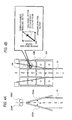
- each of the stabilizers 200A and 200A is a rectangular plate and has, on a surface thereof, a plurality of air floating portions 20A, whereby the sheet can pass through a space between the stabilizers 200A and 200A without contacting the stabilizers 200A and 200A.
- Each of the air floating potions 20A has a rectangular indentation 20K and an air outlet 20B provided in the vicinity of the center of the indentation 20K, both of which are provided on a surface of each of the stabilizers 200A.
- the air outlets 20B are connected to an air pipe 20P. Air to be blown (sprayed) from the air outlets 20B is fed from an air supply source (omitted from the drawings) on the stationary side to the air pipe 20P on the rotary device side by way of a rotary joint (omitted from the drawings), to thus reach the air outlets 20B by way of the air pipe 20P.
- the air blown from the air outlets 20B spreads over interiors of the respective indentations 20K.
- the air thus spread over the interiors of the respective indentations 20K act as contact pressure, to thus float (levitate) the sheet (resin materials).
- the entire sheet can be floated even when the air outlets 20B are not so great in numbers.
- the plurality of air floating portions 20A are provided on each of the stabilizers 200A in both its lateral and longitudinal directions.
- three air floating portions are provided in the lateral direction, and four are provided in the longitudinal direction.
- a total of 12 air floating portions are provided in close contact with each other without involvement of clearance.
- Air from the interiors of the indentations 20K acts as contact pressure, to thus float the sheet.
- the pressure-sensitive adhesive layer does not contact the stabilizers 200A, and no wrinkles, and the like, arise on the surface of the sheet.
- folding the sheet into a flattened elliptical shape becomes facilitated.
- Figs. 4A and 4B are conceptual renderings for describing a direction of conveyance of a sheet passing between the stabilizers, wherein Fig. 4A is a front view of a cylindrically-shaped sheet located in the vicinity of the stabilizer and Fig. 4B is a partially enlarged view for describing the direction of conveyance of the sheet by the air floating portions 20A.
- the two stabilizers 200A are arranged, while oriented upwardly, so as to approach each other at the angle of aperture ⁇ .
- the cylindrically inflated resin materials 10 When taken up by pinch rollers 200P positioned above the respective two stabilizers 200A, the cylindrically inflated resin materials 10 gradually become deformed from the cylindrical shape into a flattened elliptical shape while passing through the space between the two stabilizers 200A.
- immediately-above-oriented drawing force acts on a certain area 10A of the sheet, and force for causing deformation of a cylindrical shape into a flattened elliptical shape also acts on the certain area 10A in a horizontal direction at a point between the stabilizers 200A.
- the area 10A comes to move in a direction of a bubble movement resultant vector that is a combination of a drawing-direction (immediately-above-oriented) vector and a spreading-direction (the horizontal direction) vector.
- the air floating portions 20A float the sheet by means of the air originated from the entire surfaces of the air floating portions, the sheet can readily be floated in a non-contacting manner from the stabilizers 200A even when the number of the air outlets 20B is small. Therefore, respective areas of the sheet can readily move in the direction of the bubble movement resultant vector. Since the vector of the traveling direction of the sheet coincides with the direction of the bubble movement resultant vector, the sheet areas 10A do not undergo torsion.
- the sheet since the sheet is floated in a non-contacting manner, the sheet does not contact the air flowing portions 20A. Therefore, the sheet is liable to neither scratches nor generation of wrinkles. Furthermore, since the sheet is floated by air in a non-contacting manner, the pressure-sensitive adhesive layer does not come to adhere to the surfaces of the stabilizers, so that hitherto practiced periodic maintenance, such as cleaning of the surfaces of the stabilizers, becomes obviated.
- a cutter (omitted from the drawings) is placed at a location where both ends of the resin materials 10 folded into a flat shape after having passed between the pinch rollers 200P and 200P are to lie.
- the flatly folded resin materials 10 are cut into two right and left pieces with the cutter as shown in Fig. 1 .
- the thus-cut pieces are wound by take-up rollers (omitted from the drawings) situated at respective ends by way of respective right and left guide rollers 200R and 200R.
- both ends of the thus-folded resin materials are cut by means of the cutters, whereby a sheet can be doubly manufactured by single inflation as compared with the conventional technique.
- productivity is considerably enhanced.
- the inflation extrusion molding apparatus shown in Fig. 1 includes a stationary unit and a rotary unit.
- Fig. 5 is a schematic diagram showing that a rotary device is separated upwardly with a view toward making the stationary unit and the rotary unit of the inflation extrusion molding apparatus shown in Fig. 1 easy to understand.
- reference numeral 100 designates a cylindrical resin material production device (the stationary unit)
- 200 designates a one-way rotary device (the rotary unit).
- the one-way rotary device 200 includes the two stabilizers 200A and 200A fastened on a one-way rotator 200D. When the one-way rotator 200D is slowly rotated in one direction by means of a motor (omitted from the drawings), the two stabilizers 200A and 200A and take-up units (the guide rollers 200R) slowly rotate in one direction, either.
- the resin materials 10 ascent from the cylindrical resin material production device 100 enters a space between the stabilizers 200A and 200A from an opening 200H formed in the center of the one-way rotator 200D, thereby undergoing flattening. Simultaneously, the one-way rotor 200D rotates around the resin materials 10, so that the stabilizers 200A and 200A also rotate. Consequently, both folded ends of the resin materials 10 are formed at a location close to the viewer and another location distal from the viewer on a drawing sheet of Fig. 1 . When the one-way rotor 200D rotates in a direction of an arrow through 90°, both ends of the resin material 10 are formed at right and left sides on the drawing sheet.
- Figs. 6A and 6B are conceptual renderings for describing the direction of conveyance of the sheet floated by the air blown from the stabilizers when the stabilizes are rotated, wherein Fig. 6A is a lateral cross sectional view of the stabilizer and Fig. 6B is a front view.
- Fig. 6A when the stabilizers 200A rotate in a direction of an arrow, a sheet area 10A close to the stabilizers also comes to undergo the force in the rotating-direction (the horizontal direction). Consequently, the bubble movement resultant vector exerted on the sheet area 10A is equal to a result of "rotating-direction vector" being further added to the resultant vector shown in Fig. 4B .
- the bubble movement resultant vector greatly differs from the drawing-direction vector.
- the traveling direction of the sheet is free by virtue of floating effected by the air floating portions 20A adopted by the present invention. Consequently, if the direction of the bubble movement resultant vector has greatly changed from the drawing-direction vector, the sheet will move in the direction of the bubble movement resultant vector. Therefore, even when the stabilizers 200A are rotated, a problem of occurrence of wrinkles, and the like, does not arise.
- each of the stabilizers 200A and 200A is a rectangular plate and has, on a surface thereof, a plurality of air floating portions 20A.
- Each of the air floating potions 20A has a rectangular indentation 20K and an air outlet 20B provided in the vicinity of the center of the indentation 20K, both of which are provided on a surface of each of the stabilizers 200A.
- the air outlets 20B are connected to an air pipe 20P.
- a porous member 21 covers the surface of each stabilizer 210A at which the air floating portions are provided
- the material of the porous member 21 is not limited, metal materials such as stainless steel, titanium, copper, nickel, aluminum and alloys thereof; sintered body (ceramics) such as alumina (Al 2 O 3 ) and silicone carbide (SiC); glass fibers; and polymer materials such as polyethylene (PE), polypropylene (PP), ethylene/vinyl acetate copolymer (EVA), polyacetylene (PA), poly(methyl methacylate) (PMMA), acrylonitrile/styrene copolymer (AS), acrylonitrile/butadiene/styrene copolymer (ABS), polycarbonate (PC), polyvinyl chloride (PVC), poly(vinylidene fluoride) (PVDF) and polytetrafluoroethylene (PTFE).
- metal materials such as stainless steel, titanium, copper, nickel, aluminum and alloys thereof
- sintered body (ceramics) such as alumina (Al 2 O 3 ) and silicone
- the pore size of the porous member 21 is preferably 0.1 to 1,000 ⁇ m, more preferably 1 to 500 ⁇ m, and furthermore preferably 10 to 50 ⁇ m.
- the porosity of the porous member 21 is preferably 10 to 80%, more preferably 10 to 50%.
- the thickness of the porous member 21 is preferably 5 to 30 mm, more preferably 5 to 20 mm, and furthermore preferably 8 to 15 mm.
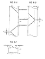
- Figs. 8-1A, 8-1B and 8-2 are views for describing a sheet which is ejected from a die that causes an area having a different thickness from others (the area is herein tentatively taken as "protuberance R") and is deformed into a flattened elliptical shape in accordance with a conventional molding apparatus.
- Figs. 8-1A and 8-1B are plan views of a sheet deformed into a flattened elliptical shape, wherein Fig. 8-1A is a plan view of one side of the sheet and Fig. 8-1B is a plan view of the other side.
- Figs. 8-2 is a front view of a take-up roll achieved when the sheet shown in Figs.
- the area having a different thickness than others is formed along a lengthwise direction of the sheet and in parallel with an edge of the same, only at a point corresponding to an angle ⁇ ° in the widthwise direction of the sheet as shown in Fig. 7-1A . Therefore, when such a sheet is rolled up as shown in Fig. 8-2 , a protuberance bulging in a circumferential direction arises in a location on the surface of the cylindrical roller corresponding to the angle ⁇ °.
- an unevenness caused by the protuberance is retained in the sheet itself. Therefore, when the sheet is withdrawn from the roll during use and affixed to an adherend, the unevenness left in the sheet itself is also left, as it is, in the form of a wrinkle on the adherend.
- 9-1A, 9-1B and 9-2 are views for describing a sheet which is ejected from the die that causes areas having a different thickness than others and is deformed into a flattened elliptical shape when an apparatus described in connection with JP-UM-B-7-30347 reciprocally rotates stabilizers through 270°
- Figs. 9-1A and 9-1B are plan views of a sheet resulting from deformation into the flattened elliptical shape, in which Fig. 9-1A is a plan view of one side of the sheet, while Fig. 9-1B is a plan view of the other side of the same, and Fig 9-2 is a front view of a roll into which the sheet shown in Figs.
- 9-1A and 9-1B is rolled up.
- the stabilizers are rotated through 270°. Therefore, during the course of rotation of the stabilizers, the protuberances R, which are the only areas having a different thickness in the widthwise direction such as those shown in Figs. 9-1A and 9-1B , obliquely proceed with respect to the edge of the sheet as the sheet runs in its lengthwise direction. Consequently, the protuberances R spread in their widthwise direction in this zone.
- the roll is made uniform as indicated by reference symbol K shown in Fig.
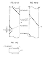
- Fig. 10-1A, 10-1B and 10-2 are views for describing a sheet which is ejected from the die that causes areas having a different thickness than others and is deformed into a flattened elliptical shape when an apparatus described in connection with JP-UM-B-7-30347 reciprocally rotates stabilizers through 360°
- Figs. 10-1A and 10-1B are plan views of a sheet resulting from deformation into the flattened elliptical shape, in which Fig. 10-1A is a plan view of one side of the sheet, while Fig. 10-1B is a plan view of the other side of the same, and Fig 10-2 is a front view of a roll into which the sheet shown in Figs.
- the stabilizers 200A are continually rotated in one direction. Accordingly, as shown in Figs. 11-1A and 11-1B , the protuberances R having a different thickness than others continually proceed (without involvement of a U-turn) in their widthwise direction. Therefore, even when both ends of the sheet in a flattened elliptical shape (flattened elliptical body) are cut with a cutter so as to be separated into two sheets and then the thus-separated two sheets are respectively rolled up, the protuberances R having a different thickness spread in their widthwise direction, to thus become uniform like K as shown in Fig. 11-2A and 11-2B . For these reasons, the protuberances (shown in Fig.
- moldable resin materials include homopolypropylene; block, random or other propylene polymers containing ethylene units as comonomer units; ethylene polymers such as low-density ethylene polymers, high-density ethylene polymers, and linear low-density ethylene polymers; polystyrene; polyesters; olefin polymers that are copolymers of ethylene and other monomer(s) such as ethylene/methyl methacrylate copolymers; styrene/isoprene/styrene block copolymers (SIS); styrene/butadiene/styrene block copolymers (SBS); styrene/isoprene block copolymers (SI); styrene/butadiene block copoly
- styrene/isoprene/styrene block copolymers SIS
- SBS styrene/butadiene/styrene block copolymers
- SI styrene/isoprene block copolymers
- SI styrene/butadiene block copolymers
- SI styrene/isoprene block copolymers
- SB styrene/butadiene block copolymers
- SEPS styrene/ethylene-propylene/styrene block copolymers
- SEBS styrene/ethylene-butylene/styrene block copolymers
- SEBS styrene/ethylene-butylene-propylene block copolymers
- SEP styrene/ethylene-butylene-propylene block copolymers
- the resin materials may be used solely or as a mixture of two or more of them.
- examples of the resin materials for forming pressure-sensitive adhesive layer include SEEPS [styrene/(ethylene-ethylene/propylene)/styrene block copolymers].
- resin materials that can be used for forming substrate layer such as thermoplastic urethane and acryl block copolymers which will be described later may be employed as a resin material for forming pressure-sensitive adhesive.
- acrylic block copolymers (A) composed of methacrylic copolymer blocks (a) containing ester of methacrylic acid as a principal component and acrylic copolymer blocks (b) containing ester of acrylic acid as a principal component may be mentioned.
- a structure of the acrylic block copolymers (A) may be either linear block copolymers or branched (star) block copolymers or a mixture thereof. Such a structure of the block copolymers is selected, as appropriate, according to physical properties of the required acrylic block copolymers (A).
- the linear block copolymers are preferable in view of cost and ease of polymerization.
- the linear block copolymers may assume either of the structures. However, provided that the methacrylic copolymer blocks (a) are taken as “a” and that the acrylic copolymer blocks (b) are taken as "b” from the viewpoint of physical properties of the linear block copolymer and physical properties of compositions, it is preferable that the linear block copolymers be composed of at least one type of acrylic block copolymers selected from the group consisting of (a-b)n-type acrylic block copolymers, b-(a-b)n-type acrylic block copolymers, and (a-b)n-a-type acrylic block copolymers ("n" is an integer of more than one; for instance, an integer from one to three). Among these acrylic block copolymers, a-b-type di-block copolymers, a-b-a-type tri-block copolymers, or a mixture thereof are preferable in view of ease of handling during processing or physical properties of compositions.
- the resin material for forming pressure-sensitive adhesive layer may also contain other components, as required.
- other components include olefin resins; silicone resins, liquid acrylic copolymers; polyethylene imines; fatty amides; phosphate esters; and common additives. Types, number, and quantity of other components to be contained in the resin material for forming pressure-sensitive adhesive layer can be appropriately set according to an objective.
- the additives include tackifiers; softeners; antioxidants; hindered amine light stabilizers; ultraviolet absorbers; and fillers or pigments, such as calcium oxide, magnesium oxide, silica or zinc oxide, and titanium oxide.
- tackifier tackifier resin
- the tackifiers include petroleum resins of an aliphatic type, an aromatic type, an aliphatic/aromatic copolymer type, or an alicyclic type; coumarone-indene resins; terpene resins; terpene-phenol resins; alkylphenol resins; rosin resins; polymerized rosin resins; xylene resins; and resins obtained by hydrogenating these resins.
- One or more appropriate materials selected from these tackifiers can be used.
- examples of the softeners include low-molecular polyiosbutylene; polybutene; polyisoprene; polybutadiene; hydrogenated polyisoprene; hydrogenated polybutadiene; derivatives thereof that have a reactive group such as an OH group, a COOH group, or an epoxy group at one end or both ends thereof; process oils; naphthenic oil; castor oil; linseed oil; soybean oil; phthalic ester plasticizers, phosphoric ester plasticizers; and liquid aliphatic petroleum resins.
- a reactive group such as an OH group, a COOH group, or an epoxy group
- resin material for forming substrate layer examples include homopolypropylene; block, random or other propylene polymers containing ethylene units as comonomer units; ethylene polymers such as low-density ethylene polymers, high-density ethylene polymers, and linear low-density ethylene polymers; polystyrene; polyesters; olefin polymers that are copolymers of ethylene and other monomer(s) such as ethylene/methyl methacrylate copolymers; styrene/isoprene/styrene block copolymers (SIS); styrene/butadiene/styrene block copolymers (SBS); styrene/isoprene block copolymers (SI); styrene/butadiene block copolymers (SB); styrene/ethylenepropylene/styrene block copolymers (SEPS); styrene/ethylene-but
- examples of the resin materials for forming substrate layer further include thermoplastic polyesters (that can be used alone), homopolypropylene (random polypropylenes and block polypropylenes may also be used), and ethylene/vinyl alcohol copolymer (EVOH).
- thermoplastic polyesters that can be used alone
- homopolypropylene random polypropylenes and block polypropylenes may also be used
- EVOH ethylene/vinyl alcohol copolymer
- the aforementioned thermoplastic urethanes and the acrylic block copolymers may also be used as the resin material for forming substrate layer.
- These resin materials may be used solely or as a mixture of two or more of them.
- the resin material for forming substrate layer may contain an appropriate additive, if necessary.
- examples of the additives that can be contained in the resin material for forming substrate layer include ultraviolet absorbers, heat-resistant stabilizers, fillers and lubricants. Types, number, and quantity of additives to be contained in the resin material for forming substrate layer can be appropriately set according to an objective.
- the ultraviolet absorbers include benzotriazole compounds, benzophenone compounds and benzoate compounds.
- an ultraviolet absorber content an arbitrary, appropriate content can be adopted unless otherwise bleed out arises during formation of a multilayered film.
- 0.01 part by weight to 5 parts by weight of a ultraviolet absorber is contained with reference to 100 parts by weight of thermoplastic resin in the substrate layer.
- heat-resistant stabilizers examples include hindered amine compounds, phosphor compounds and cyanoacrylate compounds.
- a heat-resistance stabilizer content an arbitrary, appropriate content can be adopted unless otherwise bleed out arises during formation of a multilayered film.
- 0.01 part by weight to 5 parts by weight of a heat-resistant stabilizer is contained with reference to 100 parts by weight of thermoplastic resin in the substrate layer.
- fillers examples include inorganic fillers such as talc, titanium oxide, calcium carbonate, clay, mica, barium sulfate, whisker and magnesium hydrate.
- a preferable average particle size of the filler is 0.1 ⁇ m to 10 ⁇ m.
- 1 part by weight to 200 parts by weight of a filler is preferably contained with reference to 100 parts by weight of thermoplastic resin in the substrate layer.
- the resin material for forming pressure-sensitive adhesive layer and the resin material for forming substrate layer are respectively fed into a die 120 from respective separate extruders.
- the resin material for forming pressure-sensitive adhesive layer and the resin material for forming substrate layer fed into the die 120 are then extruded together through annular openings provided in the die 120 in such a way that the resin material for forming pressure-sensitive adhesive layer becomes an exterior layer.
- the reason why the resin materials are extruded in such a way that the resin material for forming pressure-sensitive adhesive layer becomes an exterior layer is to prevent interior surfaces of a resultant pressure-sensitive adhesive sheet from adhering to each other after the sheet has been folded between the stabilizers 200A and 200A.
- the inflation extrusion molding apparatus of pressure-sensitive adhesive sheet according to the present invention makes it possible to form various resin materials, including pressure-sensitive adhesive sheets, with high quality and without involvement of occurrence of wrinkles.
- the inflation extrusion molding apparatus of the present invention is hereunder described specifically by reference to examples in which a pressure-sensitive adhesive sheet is taken by way of example.
- the inflation extrusion molding apparatus of the present invention is not limited to the following examples.
- Block polypropylene (WINTEC WFX6 manufactured by Japan Polypropylene Corporation) as a material for forming substrate layer was fed to a resin feed port 110H of a screw extruder 110 having a diameter of 60 mm.
- SEBS styrene/ethylene-butylene/styrene block copolymers
- tackifier ARKON P-125 manufactured by Arakawa Chemical Industries Ltd.
- the extruder for pressure-sensitive adhesive was operated at a revolution speed of 15 rpm, and the extruder for substrate was operated at a revolution speed of 140 rpm, so that the resin materials were poured into a die 120.
- the die 120 had a diameter of 400 mm, and the annular ejection opening was concentrically and doubly provided. A gap of each ejection opening was 3.0 mm.
- the respective resin materials were molded through coextrusion while a preset temperature of the extruder for pressure-sensitive adhesive was set to 220°C on the average; a preset temperature of the extruder for substrate was set to 180°C on the average; and a preset temperature of the die 120 was set to 220°C.
- the resin material 10 that had been molded through coextrusion and inflated into a cylindrical shape passed through a space between the stabilizers 200A and 200A, to thus be molded so as to become folded in a flattened elliptical shape.
- Employed stabilizers 200A and 200A are those shown in Figs. 3A to 3D ; in other words, a total of 12 air floating portions 20A; namely, three air floating portions 20A in the lateral direction and four air floating portions 20A in the longitudinal direction on each of the stabilizers.
- two pressure-sensitive adhesive sheets each of which measured 110 ⁇ m in thickness and 1350 mm in width, could be obtained. Surfaces of the respective sheets were free from wrinkles, and the respective sheets had a substantially uniform thickness. Thus, high quality pressure-sensitive adhesive sheets were produced.
- each of the stabilizers included a first roll unit and a second roll unit that were symmetrically arranged so as to assume an inclination angle of 6° and that were also made of PTFE.
- the first roll unit 56 narrow-width rollers, each of which had a width of 17 mm and a roll diameter of 46 mm, were provided in a row, and the respective rollers were attached at a pitch of 55 mm such that a gap between the rollers came to 9 mm.
- the row was arranged in eight layers.
- the second roll unit 90 narrow-width rollers, each of which had a width of 12 mm and a roll diameter of 38 mm, were provided in a row, and the respective rollers were attached at a pitch of 50 mm such that a gap between the rollers came to 12 mm.
- the row was arranged in two layers.
- the first roll unit and the second roll unit ware arranged such that a gap therebetween came to 8 mm.
- the narrow-width rollers were arranged in a zigzag layout, and an angle of aperture ⁇ was set to 24°.
- an inflation extrusion molding apparatus that easily folds resin material(s) into a flattened elliptical shape without involvement of occurrence of wrinkles on a surface thereof and that makes it possible to let areas of the resin material(s) having a different thickness spread.
Landscapes
- Engineering & Computer Science (AREA)
- Mechanical Engineering (AREA)
- Manufacturing & Machinery (AREA)
- Shaping By String And By Release Of Stress In Plastics And The Like (AREA)
- Extrusion Moulding Of Plastics Or The Like (AREA)
- Adhesive Tapes (AREA)
Applications Claiming Priority (2)
| Application Number | Priority Date | Filing Date | Title |
|---|---|---|---|
| JP2010073371 | 2010-03-26 | ||
| JP2010139486A JP4704507B1 (ja) | 2010-03-26 | 2010-06-18 | 粘着シートのインフレーション押出成形装置およびその方法 |
Publications (3)
| Publication Number | Publication Date |
|---|---|
| EP2368687A2 true EP2368687A2 (de) | 2011-09-28 |
| EP2368687A3 EP2368687A3 (de) | 2012-02-08 |
| EP2368687B1 EP2368687B1 (de) | 2014-01-15 |
Family
ID=44237107
Family Applications (1)
| Application Number | Title | Priority Date | Filing Date |
|---|---|---|---|
| EP10169048.5A Not-in-force EP2368687B1 (de) | 2010-03-26 | 2010-07-09 | Vorrichtung und Verfahren zum Extrusionsblasformen von druckempfindlicher Klebefolie |
Country Status (6)
| Country | Link |
|---|---|
| US (2) | US8092204B2 (de) |
| EP (1) | EP2368687B1 (de) |
| JP (1) | JP4704507B1 (de) |
| KR (1) | KR101067131B1 (de) |
| CN (2) | CN202156029U (de) |
| TW (1) | TW201132488A (de) |
Families Citing this family (3)
| Publication number | Priority date | Publication date | Assignee | Title |
|---|---|---|---|---|
| JP4704507B1 (ja) * | 2010-03-26 | 2011-06-15 | 日東電工株式会社 | 粘着シートのインフレーション押出成形装置およびその方法 |
| JP6123415B2 (ja) * | 2013-03-27 | 2017-05-10 | 三菱化学株式会社 | 水素化ブロック共重合体の回収方法および樹脂組成物 |
| CN116408963B (zh) * | 2021-12-29 | 2026-03-31 | 上海上源印务有限公司 | 一种卷膜生产用的冷风环 |
Citations (1)
| Publication number | Priority date | Publication date | Assignee | Title |
|---|---|---|---|---|
| JP2005111980A (ja) | 2003-09-17 | 2005-04-28 | Nitto Denko Corp | インフレーション押出成形方法及びそれに用いられる押出成形装置、ならびに粘着シートの製造方法 |
Family Cites Families (21)
| Publication number | Priority date | Publication date | Assignee | Title |
|---|---|---|---|---|
| NL260970A (de) * | 1960-02-08 | 1900-01-01 | ||
| DE2058033A1 (de) * | 1970-11-25 | 1972-05-31 | Windmoeller & Hoelscher | Flachlege- und Abzugsvorrichtung fuer im Blasverfahren hergestellte Kunststoffschlauchfolien |
| CH519981A (de) * | 1971-02-08 | 1972-03-15 | Windmoeller & Hoelscher | Flachlege- und Abzugvorrichtung für im Blasverfahren hergestellte Kunststoffschlauchfolien |
| JPS5538799B2 (de) | 1973-06-25 | 1980-10-06 | ||
| JPS5555831A (en) | 1978-10-18 | 1980-04-24 | Tokyo Sankei Kogyo Kk | Draw-off device in rotary system for synthetic resin tubular film |
| JPS5857922A (ja) | 1981-10-02 | 1983-04-06 | Modern Mach Kk | バブル安定板 |
| JPS5964330A (ja) | 1982-10-05 | 1984-04-12 | Modern Mach Kk | インフレ−シヨンフイルムの反転装置 |
| DE3421680C1 (de) * | 1984-06-09 | 1985-10-17 | Reifenhäuser GmbH & Co Maschinenfabrik, 5210 Troisdorf | Vorrichtung zum Flachlegen von Blasfolienschlaeuchen |
| JPS61228934A (ja) | 1985-04-03 | 1986-10-13 | Tomy Kikai Kogyo Kk | インフレ−シヨンフイルムの成形方法及び製造装置 |
| US4728277A (en) * | 1986-12-30 | 1988-03-01 | Mirek Planeta | Film-handling devices for thin flexible films |
| CA2012837A1 (en) * | 1989-04-10 | 1990-10-10 | Robert A. Taylor | Method and apparatus for formation of thermoplastic film |
| JPH0730347Y2 (ja) | 1989-12-08 | 1995-07-12 | 株式会社プラコー | フイルム成形装置における安定板 |
| DE19609638C1 (de) * | 1996-03-12 | 1997-11-13 | Windmoeller & Hoelscher | Vorrichtung zum Flachlegen eines Folienschlauches |
| US6635111B1 (en) * | 1998-12-23 | 2003-10-21 | Bachofen & Meier Ag Maschinenfabrik | Contactless guide system for continuous web |
| TW490384B (en) * | 1999-12-13 | 2002-06-11 | Sumitomo Chemical Co | Resin guiding device for inflation molding apparatus and method of producing film |
| ES2280666T3 (es) * | 2003-06-17 | 2007-09-16 | REIFENHAUSER GMBH & CO. MASCHINENFABRIK | Dispositivo para fabricar una pelicula de material sintetico termoplastico. |
| US7556762B2 (en) * | 2003-09-17 | 2009-07-07 | Nitto Denko Corporation | Method of inflation extrusion molding, extrusion molding apparatus therefor, and process for producing pressure-sensitive adhesive sheet |
| JP2007526151A (ja) | 2004-03-04 | 2007-09-13 | ヴィントメーラー ウント ヘルシャー コマンディトゲゼルシャフト | インフレートフィルム押出成形システム |
| EP2128563A1 (de) * | 2008-05-30 | 2009-12-02 | Plast-Control GmbH | Verfaren zur Messung des Dickenprofils eines Folienschlauches |
| JP4704507B1 (ja) * | 2010-03-26 | 2011-06-15 | 日東電工株式会社 | 粘着シートのインフレーション押出成形装置およびその方法 |
| TWI603715B (zh) | 2015-08-12 | 2017-11-01 | 蘇家琪 | 呼吸功能檢測系統及其檢測方法 |
-
2010
- 2010-06-18 JP JP2010139486A patent/JP4704507B1/ja not_active Expired - Fee Related
- 2010-07-08 KR KR1020100065994A patent/KR101067131B1/ko not_active Expired - Fee Related
- 2010-07-08 US US12/832,381 patent/US8092204B2/en not_active Expired - Fee Related
- 2010-07-09 EP EP10169048.5A patent/EP2368687B1/de not_active Not-in-force
- 2010-08-06 TW TW099126432A patent/TW201132488A/zh unknown
-
2011
- 2011-03-25 CN CN2011200822794U patent/CN202156029U/zh not_active Expired - Lifetime
- 2011-03-25 CN CN201110073371.9A patent/CN102198727B/zh not_active Expired - Fee Related
- 2011-11-15 US US13/296,591 patent/US8226398B2/en not_active Expired - Fee Related
Patent Citations (1)
| Publication number | Priority date | Publication date | Assignee | Title |
|---|---|---|---|---|
| JP2005111980A (ja) | 2003-09-17 | 2005-04-28 | Nitto Denko Corp | インフレーション押出成形方法及びそれに用いられる押出成形装置、ならびに粘着シートの製造方法 |
Also Published As
| Publication number | Publication date |
|---|---|
| JP2011218773A (ja) | 2011-11-04 |
| TW201132488A (en) | 2011-10-01 |
| KR101067131B1 (ko) | 2011-09-22 |
| JP4704507B1 (ja) | 2011-06-15 |
| US8092204B2 (en) | 2012-01-10 |
| EP2368687A3 (de) | 2012-02-08 |
| US20110233827A1 (en) | 2011-09-29 |
| US20120112380A1 (en) | 2012-05-10 |
| US8226398B2 (en) | 2012-07-24 |
| CN102198727A (zh) | 2011-09-28 |
| EP2368687B1 (de) | 2014-01-15 |
| CN102198727B (zh) | 2015-04-15 |
| CN202156029U (zh) | 2012-03-07 |
Similar Documents
| Publication | Publication Date | Title |
|---|---|---|
| EP1075921B1 (de) | Mehrschichtige geschäumte Polyolefin-Folie, Verfahren und Vorrichtung zur deren Herstellung | |
| CN104558857B (zh) | 丙烯与己烯‑1的共聚物和从其得到的吹塑膜 | |
| US7556762B2 (en) | Method of inflation extrusion molding, extrusion molding apparatus therefor, and process for producing pressure-sensitive adhesive sheet | |
| JP4524043B2 (ja) | ラベル | |
| CN102029709B (zh) | 一种聚合物薄膜的制造方法 | |
| CN103249546B (zh) | 胶条、其制造方法及充气轮胎的制造方法 | |
| CN103249548B (zh) | 胶条、其制造方法及充气轮胎的制造方法 | |
| JP4516214B2 (ja) | 透明ラベル | |
| EP2368687B1 (de) | Vorrichtung und Verfahren zum Extrusionsblasformen von druckempfindlicher Klebefolie | |
| CN101462353A (zh) | 生产挤出树脂板的方法 | |
| CN115697704A (zh) | 层叠薄膜 | |
| KR100860731B1 (ko) | 수지의 필름상 물질 제조방법 및 수지의 필름상 물질 | |
| EP1693195A2 (de) | Laminat-Herstellungsverfahren und Vorrichtung | |
| JP2016215489A (ja) | 包装材料用シーラントフィルムの製造方法 | |
| JP2012200906A (ja) | ストレッチフィルム、筒状ストレッチラベルおよびラベル付き容器 | |
| JP4574260B2 (ja) | 樹脂フィルムの製造方法及び樹脂フィルム成形用エッジピンニング装置 | |
| JP2015134451A (ja) | 延伸フィルムの製造方法 | |
| JP4749574B2 (ja) | 樹脂製フィルム状物の製造方法 | |
| CN119872043B (zh) | 一种热弯冲压保护膜及其制备方法和应用 | |
| JP4726353B2 (ja) | ポリアミド系同時二軸延伸積層フィルムの製造方法 | |
| JP2003340921A (ja) | ポリアミド系同時2軸延伸積層フィルムの製造方法 |
Legal Events
| Date | Code | Title | Description |
|---|---|---|---|
| PUAI | Public reference made under article 153(3) epc to a published international application that has entered the european phase |
Free format text: ORIGINAL CODE: 0009012 |
|
| AK | Designated contracting states |
Kind code of ref document: A2 Designated state(s): AL AT BE BG CH CY CZ DE DK EE ES FI FR GB GR HR HU IE IS IT LI LT LU LV MC MK MT NL NO PL PT RO SE SI SK SM TR |
|
| AX | Request for extension of the european patent |
Extension state: BA ME RS |
|
| PUAL | Search report despatched |
Free format text: ORIGINAL CODE: 0009013 |
|
| AK | Designated contracting states |
Kind code of ref document: A3 Designated state(s): AL AT BE BG CH CY CZ DE DK EE ES FI FR GB GR HR HU IE IS IT LI LT LU LV MC MK MT NL NO PL PT RO SE SI SK SM TR |
|
| AX | Request for extension of the european patent |
Extension state: BA ME RS |
|
| RIC1 | Information provided on ipc code assigned before grant |
Ipc: B29C 69/00 20060101ALI20111230BHEP Ipc: B29C 49/04 20060101ALN20111230BHEP Ipc: B29C 47/00 20060101AFI20111230BHEP Ipc: B29C 47/90 20060101ALI20111230BHEP |
|
| 17P | Request for examination filed |
Effective date: 20120509 |
|
| RIC1 | Information provided on ipc code assigned before grant |
Ipc: B29C 47/00 20060101AFI20130711BHEP Ipc: B29C 49/04 20060101ALN20130711BHEP Ipc: B29C 69/00 20060101ALI20130711BHEP Ipc: B29C 47/90 20060101ALI20130711BHEP |
|
| GRAP | Despatch of communication of intention to grant a patent |
Free format text: ORIGINAL CODE: EPIDOSNIGR1 |
|
| INTG | Intention to grant announced |
Effective date: 20130822 |
|
| GRAS | Grant fee paid |
Free format text: ORIGINAL CODE: EPIDOSNIGR3 |
|
| GRAA | (expected) grant |
Free format text: ORIGINAL CODE: 0009210 |
|
| AK | Designated contracting states |
Kind code of ref document: B1 Designated state(s): AL AT BE BG CH CY CZ DE DK EE ES FI FR GB GR HR HU IE IS IT LI LT LU LV MC MK MT NL NO PL PT RO SE SI SK SM TR |
|
| REG | Reference to a national code |
Ref country code: CH Ref legal event code: EP Ref country code: GB Ref legal event code: FG4D |
|
| REG | Reference to a national code |
Ref country code: AT Ref legal event code: REF Ref document number: 649599 Country of ref document: AT Kind code of ref document: T Effective date: 20140215 |
|
| REG | Reference to a national code |
Ref country code: IE Ref legal event code: FG4D |
|
| REG | Reference to a national code |
Ref country code: DE Ref legal event code: R096 Ref document number: 602010013099 Country of ref document: DE Effective date: 20140227 |
|
| REG | Reference to a national code |
Ref country code: NL Ref legal event code: VDEP Effective date: 20140115 |
|
| REG | Reference to a national code |
Ref country code: AT Ref legal event code: MK05 Ref document number: 649599 Country of ref document: AT Kind code of ref document: T Effective date: 20140115 |
|
| REG | Reference to a national code |
Ref country code: LT Ref legal event code: MG4D |
|
| PG25 | Lapsed in a contracting state [announced via postgrant information from national office to epo] |
Ref country code: IS Free format text: LAPSE BECAUSE OF FAILURE TO SUBMIT A TRANSLATION OF THE DESCRIPTION OR TO PAY THE FEE WITHIN THE PRESCRIBED TIME-LIMIT Effective date: 20140515 Ref country code: NO Free format text: LAPSE BECAUSE OF FAILURE TO SUBMIT A TRANSLATION OF THE DESCRIPTION OR TO PAY THE FEE WITHIN THE PRESCRIBED TIME-LIMIT Effective date: 20140415 Ref country code: LT Free format text: LAPSE BECAUSE OF FAILURE TO SUBMIT A TRANSLATION OF THE DESCRIPTION OR TO PAY THE FEE WITHIN THE PRESCRIBED TIME-LIMIT Effective date: 20140115 |
|
| PG25 | Lapsed in a contracting state [announced via postgrant information from national office to epo] |
Ref country code: ES Free format text: LAPSE BECAUSE OF FAILURE TO SUBMIT A TRANSLATION OF THE DESCRIPTION OR TO PAY THE FEE WITHIN THE PRESCRIBED TIME-LIMIT Effective date: 20140115 Ref country code: FI Free format text: LAPSE BECAUSE OF FAILURE TO SUBMIT A TRANSLATION OF THE DESCRIPTION OR TO PAY THE FEE WITHIN THE PRESCRIBED TIME-LIMIT Effective date: 20140115 Ref country code: SE Free format text: LAPSE BECAUSE OF FAILURE TO SUBMIT A TRANSLATION OF THE DESCRIPTION OR TO PAY THE FEE WITHIN THE PRESCRIBED TIME-LIMIT Effective date: 20140115 Ref country code: CY Free format text: LAPSE BECAUSE OF FAILURE TO SUBMIT A TRANSLATION OF THE DESCRIPTION OR TO PAY THE FEE WITHIN THE PRESCRIBED TIME-LIMIT Effective date: 20140115 Ref country code: PT Free format text: LAPSE BECAUSE OF FAILURE TO SUBMIT A TRANSLATION OF THE DESCRIPTION OR TO PAY THE FEE WITHIN THE PRESCRIBED TIME-LIMIT Effective date: 20140515 Ref country code: NL Free format text: LAPSE BECAUSE OF FAILURE TO SUBMIT A TRANSLATION OF THE DESCRIPTION OR TO PAY THE FEE WITHIN THE PRESCRIBED TIME-LIMIT Effective date: 20140115 Ref country code: AT Free format text: LAPSE BECAUSE OF FAILURE TO SUBMIT A TRANSLATION OF THE DESCRIPTION OR TO PAY THE FEE WITHIN THE PRESCRIBED TIME-LIMIT Effective date: 20140115 |
|
| PG25 | Lapsed in a contracting state [announced via postgrant information from national office to epo] |
Ref country code: HR Free format text: LAPSE BECAUSE OF FAILURE TO SUBMIT A TRANSLATION OF THE DESCRIPTION OR TO PAY THE FEE WITHIN THE PRESCRIBED TIME-LIMIT Effective date: 20140115 Ref country code: LV Free format text: LAPSE BECAUSE OF FAILURE TO SUBMIT A TRANSLATION OF THE DESCRIPTION OR TO PAY THE FEE WITHIN THE PRESCRIBED TIME-LIMIT Effective date: 20140115 |
|
| REG | Reference to a national code |
Ref country code: DE Ref legal event code: R097 Ref document number: 602010013099 Country of ref document: DE |
|
| PG25 | Lapsed in a contracting state [announced via postgrant information from national office to epo] |
Ref country code: RO Free format text: LAPSE BECAUSE OF FAILURE TO SUBMIT A TRANSLATION OF THE DESCRIPTION OR TO PAY THE FEE WITHIN THE PRESCRIBED TIME-LIMIT Effective date: 20140115 Ref country code: EE Free format text: LAPSE BECAUSE OF FAILURE TO SUBMIT A TRANSLATION OF THE DESCRIPTION OR TO PAY THE FEE WITHIN THE PRESCRIBED TIME-LIMIT Effective date: 20140115 Ref country code: CZ Free format text: LAPSE BECAUSE OF FAILURE TO SUBMIT A TRANSLATION OF THE DESCRIPTION OR TO PAY THE FEE WITHIN THE PRESCRIBED TIME-LIMIT Effective date: 20140115 Ref country code: DK Free format text: LAPSE BECAUSE OF FAILURE TO SUBMIT A TRANSLATION OF THE DESCRIPTION OR TO PAY THE FEE WITHIN THE PRESCRIBED TIME-LIMIT Effective date: 20140115 |
|
| PLBE | No opposition filed within time limit |
Free format text: ORIGINAL CODE: 0009261 |
|
| STAA | Information on the status of an ep patent application or granted ep patent |
Free format text: STATUS: NO OPPOSITION FILED WITHIN TIME LIMIT |
|
| PG25 | Lapsed in a contracting state [announced via postgrant information from national office to epo] |
Ref country code: PL Free format text: LAPSE BECAUSE OF FAILURE TO SUBMIT A TRANSLATION OF THE DESCRIPTION OR TO PAY THE FEE WITHIN THE PRESCRIBED TIME-LIMIT Effective date: 20140115 Ref country code: SK Free format text: LAPSE BECAUSE OF FAILURE TO SUBMIT A TRANSLATION OF THE DESCRIPTION OR TO PAY THE FEE WITHIN THE PRESCRIBED TIME-LIMIT Effective date: 20140115 |
|
| 26N | No opposition filed |
Effective date: 20141016 |
|
| REG | Reference to a national code |
Ref country code: DE Ref legal event code: R097 Ref document number: 602010013099 Country of ref document: DE Effective date: 20141016 |
|
| PG25 | Lapsed in a contracting state [announced via postgrant information from national office to epo] |
Ref country code: LU Free format text: LAPSE BECAUSE OF FAILURE TO SUBMIT A TRANSLATION OF THE DESCRIPTION OR TO PAY THE FEE WITHIN THE PRESCRIBED TIME-LIMIT Effective date: 20140709 |
|
| REG | Reference to a national code |
Ref country code: CH Ref legal event code: PL |
|
| GBPC | Gb: european patent ceased through non-payment of renewal fee |
Effective date: 20140709 |
|
| REG | Reference to a national code |
Ref country code: IE Ref legal event code: MM4A |
|
| PG25 | Lapsed in a contracting state [announced via postgrant information from national office to epo] |
Ref country code: CH Free format text: LAPSE BECAUSE OF NON-PAYMENT OF DUE FEES Effective date: 20140731 Ref country code: LI Free format text: LAPSE BECAUSE OF NON-PAYMENT OF DUE FEES Effective date: 20140731 |
|
| PG25 | Lapsed in a contracting state [announced via postgrant information from national office to epo] |
Ref country code: SI Free format text: LAPSE BECAUSE OF FAILURE TO SUBMIT A TRANSLATION OF THE DESCRIPTION OR TO PAY THE FEE WITHIN THE PRESCRIBED TIME-LIMIT Effective date: 20140115 Ref country code: GB Free format text: LAPSE BECAUSE OF NON-PAYMENT OF DUE FEES Effective date: 20140709 |
|
| PG25 | Lapsed in a contracting state [announced via postgrant information from national office to epo] |
Ref country code: IE Free format text: LAPSE BECAUSE OF NON-PAYMENT OF DUE FEES Effective date: 20140709 |
|
| PG25 | Lapsed in a contracting state [announced via postgrant information from national office to epo] |
Ref country code: SM Free format text: LAPSE BECAUSE OF FAILURE TO SUBMIT A TRANSLATION OF THE DESCRIPTION OR TO PAY THE FEE WITHIN THE PRESCRIBED TIME-LIMIT Effective date: 20140115 Ref country code: MC Free format text: LAPSE BECAUSE OF FAILURE TO SUBMIT A TRANSLATION OF THE DESCRIPTION OR TO PAY THE FEE WITHIN THE PRESCRIBED TIME-LIMIT Effective date: 20140115 |
|
| REG | Reference to a national code |
Ref country code: FR Ref legal event code: PLFP Year of fee payment: 7 |
|
| PG25 | Lapsed in a contracting state [announced via postgrant information from national office to epo] |
Ref country code: GR Free format text: LAPSE BECAUSE OF FAILURE TO SUBMIT A TRANSLATION OF THE DESCRIPTION OR TO PAY THE FEE WITHIN THE PRESCRIBED TIME-LIMIT Effective date: 20140416 Ref country code: BG Free format text: LAPSE BECAUSE OF FAILURE TO SUBMIT A TRANSLATION OF THE DESCRIPTION OR TO PAY THE FEE WITHIN THE PRESCRIBED TIME-LIMIT Effective date: 20140115 Ref country code: MT Free format text: LAPSE BECAUSE OF FAILURE TO SUBMIT A TRANSLATION OF THE DESCRIPTION OR TO PAY THE FEE WITHIN THE PRESCRIBED TIME-LIMIT Effective date: 20140115 |
|
| PG25 | Lapsed in a contracting state [announced via postgrant information from national office to epo] |
Ref country code: HU Free format text: LAPSE BECAUSE OF FAILURE TO SUBMIT A TRANSLATION OF THE DESCRIPTION OR TO PAY THE FEE WITHIN THE PRESCRIBED TIME-LIMIT; INVALID AB INITIO Effective date: 20100709 |
|
| PGFP | Annual fee paid to national office [announced via postgrant information from national office to epo] |
Ref country code: BE Payment date: 20160613 Year of fee payment: 7 Ref country code: FR Payment date: 20160613 Year of fee payment: 7 Ref country code: TR Payment date: 20160623 Year of fee payment: 7 |
|
| PGFP | Annual fee paid to national office [announced via postgrant information from national office to epo] |
Ref country code: DE Payment date: 20160705 Year of fee payment: 7 Ref country code: IT Payment date: 20160720 Year of fee payment: 7 |
|
| REG | Reference to a national code |
Ref country code: DE Ref legal event code: R119 Ref document number: 602010013099 Country of ref document: DE |
|
| REG | Reference to a national code |
Ref country code: FR Ref legal event code: ST Effective date: 20180330 |
|
| PG25 | Lapsed in a contracting state [announced via postgrant information from national office to epo] |
Ref country code: DE Free format text: LAPSE BECAUSE OF NON-PAYMENT OF DUE FEES Effective date: 20180201 |
|
| REG | Reference to a national code |
Ref country code: BE Ref legal event code: MM Effective date: 20170731 |
|
| PG25 | Lapsed in a contracting state [announced via postgrant information from national office to epo] |
Ref country code: FR Free format text: LAPSE BECAUSE OF NON-PAYMENT OF DUE FEES Effective date: 20170731 |
|
| PG25 | Lapsed in a contracting state [announced via postgrant information from national office to epo] |
Ref country code: MK Free format text: LAPSE BECAUSE OF FAILURE TO SUBMIT A TRANSLATION OF THE DESCRIPTION OR TO PAY THE FEE WITHIN THE PRESCRIBED TIME-LIMIT Effective date: 20140115 |
|
| PG25 | Lapsed in a contracting state [announced via postgrant information from national office to epo] |
Ref country code: BE Free format text: LAPSE BECAUSE OF NON-PAYMENT OF DUE FEES Effective date: 20170731 Ref country code: IT Free format text: LAPSE BECAUSE OF NON-PAYMENT OF DUE FEES Effective date: 20170709 |
|
| PG25 | Lapsed in a contracting state [announced via postgrant information from national office to epo] |
Ref country code: AL Free format text: LAPSE BECAUSE OF FAILURE TO SUBMIT A TRANSLATION OF THE DESCRIPTION OR TO PAY THE FEE WITHIN THE PRESCRIBED TIME-LIMIT Effective date: 20140115 |
|
| PG25 | Lapsed in a contracting state [announced via postgrant information from national office to epo] |
Ref country code: TR Free format text: LAPSE BECAUSE OF NON-PAYMENT OF DUE FEES Effective date: 20170709 |