EP2372405A1 - Linse und Verfahren zur Linsenherstellung - Google Patents
Linse und Verfahren zur Linsenherstellung Download PDFInfo
- Publication number
- EP2372405A1 EP2372405A1 EP11002266A EP11002266A EP2372405A1 EP 2372405 A1 EP2372405 A1 EP 2372405A1 EP 11002266 A EP11002266 A EP 11002266A EP 11002266 A EP11002266 A EP 11002266A EP 2372405 A1 EP2372405 A1 EP 2372405A1
- Authority
- EP
- European Patent Office
- Prior art keywords
- radiation
- lens
- composition
- polymerizable composition
- particles
- Prior art date
- Legal status (The legal status is an assumption and is not a legal conclusion. Google has not performed a legal analysis and makes no representation as to the accuracy of the status listed.)
- Withdrawn
Links
- 238000004519 manufacturing process Methods 0.000 title claims description 14
- 239000002245 particle Substances 0.000 claims abstract description 89
- 239000000178 monomer Substances 0.000 claims abstract description 83
- 229920000642 polymer Polymers 0.000 claims abstract description 75
- 238000009826 distribution Methods 0.000 claims abstract description 57
- 230000005855 radiation Effects 0.000 claims description 191
- 239000000203 mixture Substances 0.000 claims description 184
- 238000005266 casting Methods 0.000 claims description 74
- 229920001577 copolymer Polymers 0.000 claims description 26
- 229920001519 homopolymer Polymers 0.000 claims description 17
- RVTZCBVAJQQJTK-UHFFFAOYSA-N oxygen(2-);zirconium(4+) Chemical compound [O-2].[O-2].[Zr+4] RVTZCBVAJQQJTK-UHFFFAOYSA-N 0.000 claims description 16
- 229910001928 zirconium oxide Inorganic materials 0.000 claims description 16
- 239000003505 polymerization initiator Substances 0.000 claims description 15
- AOJOEFVRHOZDFN-UHFFFAOYSA-N benzyl 2-methylprop-2-enoate Chemical compound CC(=C)C(=O)OCC1=CC=CC=C1 AOJOEFVRHOZDFN-UHFFFAOYSA-N 0.000 claims description 11
- 239000007788 liquid Substances 0.000 claims description 8
- VVQNEPGJFQJSBK-UHFFFAOYSA-N Methyl methacrylate Chemical compound COC(=O)C(C)=C VVQNEPGJFQJSBK-UHFFFAOYSA-N 0.000 claims description 7
- 238000007334 copolymerization reaction Methods 0.000 claims description 7
- 238000000034 method Methods 0.000 claims description 7
- DAKWPKUUDNSNPN-UHFFFAOYSA-N Trimethylolpropane triacrylate Chemical compound C=CC(=O)OCC(CC)(COC(=O)C=C)COC(=O)C=C DAKWPKUUDNSNPN-UHFFFAOYSA-N 0.000 claims description 5
- GWYSWOQRJGLJPA-UHFFFAOYSA-N 1,1,2,2-tetrafluoropropyl 2-methylprop-2-enoate Chemical compound CC(=C)C(=O)OC(F)(F)C(C)(F)F GWYSWOQRJGLJPA-UHFFFAOYSA-N 0.000 claims description 2
- RTZKZFJDLAIYFH-UHFFFAOYSA-N Diethyl ether Chemical compound CCOCC RTZKZFJDLAIYFH-UHFFFAOYSA-N 0.000 description 94
- NIXOWILDQLNWCW-UHFFFAOYSA-M Acrylate Chemical compound [O-]C(=O)C=C NIXOWILDQLNWCW-UHFFFAOYSA-M 0.000 description 78
- -1 methacryloyl group Chemical group 0.000 description 45
- 238000005259 measurement Methods 0.000 description 25
- 150000001875 compounds Chemical class 0.000 description 24
- 150000003254 radicals Chemical class 0.000 description 24
- 230000003287 optical effect Effects 0.000 description 16
- 238000009792 diffusion process Methods 0.000 description 14
- QNODIIQQMGDSEF-UHFFFAOYSA-N (1-hydroxycyclohexyl)-phenylmethanone Chemical compound C=1C=CC=CC=1C(=O)C1(O)CCCCC1 QNODIIQQMGDSEF-UHFFFAOYSA-N 0.000 description 13
- LYCAIKOWRPUZTN-UHFFFAOYSA-N Ethylene glycol Chemical compound OCCO LYCAIKOWRPUZTN-UHFFFAOYSA-N 0.000 description 13
- QYKIQEUNHZKYBP-UHFFFAOYSA-N Vinyl ether Chemical group C=COC=C QYKIQEUNHZKYBP-UHFFFAOYSA-N 0.000 description 13
- TXBCBTDQIULDIA-UHFFFAOYSA-N 2-[[3-hydroxy-2,2-bis(hydroxymethyl)propoxy]methyl]-2-(hydroxymethyl)propane-1,3-diol Chemical compound OCC(CO)(CO)COCC(CO)(CO)CO TXBCBTDQIULDIA-UHFFFAOYSA-N 0.000 description 11
- 229920003023 plastic Polymers 0.000 description 10
- 239000004033 plastic Substances 0.000 description 10
- 238000006116 polymerization reaction Methods 0.000 description 10
- UHOVQNZJYSORNB-UHFFFAOYSA-N Benzene Chemical compound C1=CC=CC=C1 UHOVQNZJYSORNB-UHFFFAOYSA-N 0.000 description 9
- 125000003647 acryloyl group Chemical group O=C([*])C([H])=C([H])[H] 0.000 description 9
- 239000005304 optical glass Substances 0.000 description 9
- 239000003504 photosensitizing agent Substances 0.000 description 9
- ATUOYWHBWRKTHZ-UHFFFAOYSA-N Propane Chemical compound CCC ATUOYWHBWRKTHZ-UHFFFAOYSA-N 0.000 description 8
- 239000003795 chemical substances by application Substances 0.000 description 8
- 229920001223 polyethylene glycol Polymers 0.000 description 8
- 229960000834 vinyl ether Drugs 0.000 description 8
- IAYPIBMASNFSPL-UHFFFAOYSA-N Ethylene oxide Chemical compound C1CO1 IAYPIBMASNFSPL-UHFFFAOYSA-N 0.000 description 7
- 239000002202 Polyethylene glycol Substances 0.000 description 7
- 239000002253 acid Substances 0.000 description 7
- 238000010438 heat treatment Methods 0.000 description 7
- HRPVXLWXLXDGHG-UHFFFAOYSA-N Acrylamide Chemical compound NC(=O)C=C HRPVXLWXLXDGHG-UHFFFAOYSA-N 0.000 description 6
- GOOHAUXETOMSMM-UHFFFAOYSA-N Propylene oxide Chemical compound CC1CO1 GOOHAUXETOMSMM-UHFFFAOYSA-N 0.000 description 6
- ZJCCRDAZUWHFQH-UHFFFAOYSA-N Trimethylolpropane Chemical group CCC(CO)(CO)CO ZJCCRDAZUWHFQH-UHFFFAOYSA-N 0.000 description 6
- 125000002496 methyl group Chemical group [H]C([H])([H])* 0.000 description 6
- JGTNAGYHADQMCM-UHFFFAOYSA-N perfluorobutanesulfonic acid Chemical compound OS(=O)(=O)C(F)(F)C(F)(F)C(F)(F)C(F)(F)F JGTNAGYHADQMCM-UHFFFAOYSA-N 0.000 description 6
- 239000000126 substance Substances 0.000 description 6
- DTGKSKDOIYIVQL-WEDXCCLWSA-N (+)-borneol Chemical group C1C[C@@]2(C)[C@@H](O)C[C@@H]1C2(C)C DTGKSKDOIYIVQL-WEDXCCLWSA-N 0.000 description 5
- IISBACLAFKSPIT-UHFFFAOYSA-N Bisphenol A Natural products C=1C=C(O)C=CC=1C(C)(C)C1=CC=C(O)C=C1 IISBACLAFKSPIT-UHFFFAOYSA-N 0.000 description 5
- 125000002091 cationic group Chemical group 0.000 description 5
- 238000006243 chemical reaction Methods 0.000 description 5
- 239000000463 material Substances 0.000 description 5
- QSHDDOUJBYECFT-UHFFFAOYSA-N mercury Chemical compound [Hg] QSHDDOUJBYECFT-UHFFFAOYSA-N 0.000 description 5
- WMYINDVYGQKYMI-UHFFFAOYSA-N 2-[2,2-bis(hydroxymethyl)butoxymethyl]-2-ethylpropane-1,3-diol Chemical compound CCC(CO)(CO)COCC(CC)(CO)CO WMYINDVYGQKYMI-UHFFFAOYSA-N 0.000 description 4
- VYPSYNLAJGMNEJ-UHFFFAOYSA-N Silicium dioxide Chemical compound O=[Si]=O VYPSYNLAJGMNEJ-UHFFFAOYSA-N 0.000 description 4
- 230000004075 alteration Effects 0.000 description 4
- GYZLOYUZLJXAJU-UHFFFAOYSA-N diglycidyl ether Chemical compound C1OC1COCC1CO1 GYZLOYUZLJXAJU-UHFFFAOYSA-N 0.000 description 4
- 239000006185 dispersion Substances 0.000 description 4
- 125000003700 epoxy group Chemical group 0.000 description 4
- 125000003566 oxetanyl group Chemical group 0.000 description 4
- WXZMFSXDPGVJKK-UHFFFAOYSA-N pentaerythritol Chemical compound OCC(CO)(CO)CO WXZMFSXDPGVJKK-UHFFFAOYSA-N 0.000 description 4
- 125000001997 phenyl group Chemical group [H]C1=C([H])C([H])=C(*)C([H])=C1[H] 0.000 description 4
- 229920001451 polypropylene glycol Polymers 0.000 description 4
- 239000001294 propane Substances 0.000 description 4
- XDWRKTULOHXYGN-UHFFFAOYSA-N 1,3-bis(ethenoxy)-2,2-bis(ethenoxymethyl)propane Chemical compound C=COCC(COC=C)(COC=C)COC=C XDWRKTULOHXYGN-UHFFFAOYSA-N 0.000 description 3
- CZAVRNDQSIORTH-UHFFFAOYSA-N 1-ethenoxy-2,2-bis(ethenoxymethyl)butane Chemical compound C=COCC(CC)(COC=C)COC=C CZAVRNDQSIORTH-UHFFFAOYSA-N 0.000 description 3
- YLZOPXRUQYQQID-UHFFFAOYSA-N 3-(2,4,6,7-tetrahydrotriazolo[4,5-c]pyridin-5-yl)-1-[4-[2-[[3-(trifluoromethoxy)phenyl]methylamino]pyrimidin-5-yl]piperazin-1-yl]propan-1-one Chemical compound N1N=NC=2CN(CCC=21)CCC(=O)N1CCN(CC1)C=1C=NC(=NC=1)NCC1=CC(=CC=C1)OC(F)(F)F YLZOPXRUQYQQID-UHFFFAOYSA-N 0.000 description 3
- VPWNQTHUCYMVMZ-UHFFFAOYSA-N 4,4'-sulfonyldiphenol Chemical compound C1=CC(O)=CC=C1S(=O)(=O)C1=CC=C(O)C=C1 VPWNQTHUCYMVMZ-UHFFFAOYSA-N 0.000 description 3
- KWOLFJPFCHCOCG-UHFFFAOYSA-N Acetophenone Chemical compound CC(=O)C1=CC=CC=C1 KWOLFJPFCHCOCG-UHFFFAOYSA-N 0.000 description 3
- LCFVJGUPQDGYKZ-UHFFFAOYSA-N Bisphenol A diglycidyl ether Chemical compound C=1C=C(OCC2OC2)C=CC=1C(C)(C)C(C=C1)=CC=C1OCC1CO1 LCFVJGUPQDGYKZ-UHFFFAOYSA-N 0.000 description 3
- 239000004593 Epoxy Substances 0.000 description 3
- 239000007983 Tris buffer Substances 0.000 description 3
- ISAOCJYIOMOJEB-UHFFFAOYSA-N benzoin Chemical class C=1C=CC=CC=1C(O)C(=O)C1=CC=CC=C1 ISAOCJYIOMOJEB-UHFFFAOYSA-N 0.000 description 3
- XUCHXOAWJMEFLF-UHFFFAOYSA-N bisphenol F diglycidyl ether Chemical compound C1OC1COC(C=C1)=CC=C1CC(C=C1)=CC=C1OCC1CO1 XUCHXOAWJMEFLF-UHFFFAOYSA-N 0.000 description 3
- 230000008859 change Effects 0.000 description 3
- 230000003247 decreasing effect Effects 0.000 description 3
- 238000010894 electron beam technology Methods 0.000 description 3
- 125000000524 functional group Chemical group 0.000 description 3
- 230000000873 masking effect Effects 0.000 description 3
- 238000002156 mixing Methods 0.000 description 3
- VLKZOEOYAKHREP-UHFFFAOYSA-N n-Hexane Chemical compound CCCCCC VLKZOEOYAKHREP-UHFFFAOYSA-N 0.000 description 3
- NFHFRUOZVGFOOS-UHFFFAOYSA-N palladium;triphenylphosphane Chemical compound [Pd].C1=CC=CC=C1P(C=1C=CC=CC=1)C1=CC=CC=C1.C1=CC=CC=C1P(C=1C=CC=CC=1)C1=CC=CC=C1.C1=CC=CC=C1P(C=1C=CC=CC=1)C1=CC=CC=C1.C1=CC=CC=C1P(C=1C=CC=CC=1)C1=CC=CC=C1 NFHFRUOZVGFOOS-UHFFFAOYSA-N 0.000 description 3
- 239000011164 primary particle Substances 0.000 description 3
- 229920005989 resin Polymers 0.000 description 3
- 239000011347 resin Substances 0.000 description 3
- 125000006850 spacer group Chemical group 0.000 description 3
- 150000003871 sulfonates Chemical class 0.000 description 3
- YRHRIQCWCFGUEQ-UHFFFAOYSA-N thioxanthen-9-one Chemical class C1=CC=C2C(=O)C3=CC=CC=C3SC2=C1 YRHRIQCWCFGUEQ-UHFFFAOYSA-N 0.000 description 3
- XOLBLPGZBRYERU-UHFFFAOYSA-N tin dioxide Chemical compound O=[Sn]=O XOLBLPGZBRYERU-UHFFFAOYSA-N 0.000 description 3
- 238000002834 transmittance Methods 0.000 description 3
- FRASJONUBLZVQX-UHFFFAOYSA-N 1,4-naphthoquinone Chemical compound C1=CC=C2C(=O)C=CC(=O)C2=C1 FRASJONUBLZVQX-UHFFFAOYSA-N 0.000 description 2
- 125000000954 2-hydroxyethyl group Chemical group [H]C([*])([H])C([H])([H])O[H] 0.000 description 2
- NJWGQARXZDRHCD-UHFFFAOYSA-N 2-methylanthraquinone Chemical compound C1=CC=C2C(=O)C3=CC(C)=CC=C3C(=O)C2=C1 NJWGQARXZDRHCD-UHFFFAOYSA-N 0.000 description 2
- VVBLNCFGVYUYGU-UHFFFAOYSA-N 4,4'-Bis(dimethylamino)benzophenone Chemical compound C1=CC(N(C)C)=CC=C1C(=O)C1=CC=C(N(C)C)C=C1 VVBLNCFGVYUYGU-UHFFFAOYSA-N 0.000 description 2
- YYVYAPXYZVYDHN-UHFFFAOYSA-N 9,10-phenanthroquinone Chemical compound C1=CC=C2C(=O)C(=O)C3=CC=CC=C3C2=C1 YYVYAPXYZVYDHN-UHFFFAOYSA-N 0.000 description 2
- UJOBWOGCFQCDNV-UHFFFAOYSA-N 9H-carbazole Chemical compound C1=CC=C2C3=CC=CC=C3NC2=C1 UJOBWOGCFQCDNV-UHFFFAOYSA-N 0.000 description 2
- PXKLMJQFEQBVLD-UHFFFAOYSA-N Bisphenol F Natural products C1=CC(O)=CC=C1CC1=CC=C(O)C=C1 PXKLMJQFEQBVLD-UHFFFAOYSA-N 0.000 description 2
- YXHKONLOYHBTNS-UHFFFAOYSA-N Diazomethane Chemical class C=[N+]=[N-] YXHKONLOYHBTNS-UHFFFAOYSA-N 0.000 description 2
- UQSXHKLRYXJYBZ-UHFFFAOYSA-N Iron oxide Chemical compound [Fe]=O UQSXHKLRYXJYBZ-UHFFFAOYSA-N 0.000 description 2
- MJVAVZPDRWSRRC-UHFFFAOYSA-N Menadione Chemical compound C1=CC=C2C(=O)C(C)=CC(=O)C2=C1 MJVAVZPDRWSRRC-UHFFFAOYSA-N 0.000 description 2
- IMNFDUFMRHMDMM-UHFFFAOYSA-N N-Heptane Chemical compound CCCCCCC IMNFDUFMRHMDMM-UHFFFAOYSA-N 0.000 description 2
- NPKSPKHJBVJUKB-UHFFFAOYSA-N N-phenylglycine Chemical class OC(=O)CNC1=CC=CC=C1 NPKSPKHJBVJUKB-UHFFFAOYSA-N 0.000 description 2
- GWEVSGVZZGPLCZ-UHFFFAOYSA-N Titan oxide Chemical compound O=[Ti]=O GWEVSGVZZGPLCZ-UHFFFAOYSA-N 0.000 description 2
- YXFVVABEGXRONW-UHFFFAOYSA-N Toluene Chemical compound CC1=CC=CC=C1 YXFVVABEGXRONW-UHFFFAOYSA-N 0.000 description 2
- 239000005083 Zinc sulfide Substances 0.000 description 2
- QCWXUUIWCKQGHC-UHFFFAOYSA-N Zirconium Chemical group [Zr] QCWXUUIWCKQGHC-UHFFFAOYSA-N 0.000 description 2
- 238000000149 argon plasma sintering Methods 0.000 description 2
- HUMNYLRZRPPJDN-UHFFFAOYSA-N benzaldehyde Chemical compound O=CC1=CC=CC=C1 HUMNYLRZRPPJDN-UHFFFAOYSA-N 0.000 description 2
- 150000008366 benzophenones Chemical class 0.000 description 2
- 125000001797 benzyl group Chemical group [H]C1=C([H])C([H])=C(C([H])=C1[H])C([H])([H])* 0.000 description 2
- WERYXYBDKMZEQL-UHFFFAOYSA-N butane-1,4-diol Chemical compound OCCCCO WERYXYBDKMZEQL-UHFFFAOYSA-N 0.000 description 2
- 125000006226 butoxyethyl group Chemical group 0.000 description 2
- JHRWWRDRBPCWTF-OLQVQODUSA-N captafol Chemical class C1C=CC[C@H]2C(=O)N(SC(Cl)(Cl)C(Cl)Cl)C(=O)[C@H]21 JHRWWRDRBPCWTF-OLQVQODUSA-N 0.000 description 2
- 229910000420 cerium oxide Inorganic materials 0.000 description 2
- 238000004140 cleaning Methods 0.000 description 2
- 230000007423 decrease Effects 0.000 description 2
- 239000010432 diamond Substances 0.000 description 2
- 229910003460 diamond Inorganic materials 0.000 description 2
- 125000003438 dodecyl group Chemical group [H]C([H])([H])C([H])([H])C([H])([H])C([H])([H])C([H])([H])C([H])([H])C([H])([H])C([H])([H])C([H])([H])C([H])([H])C([H])([H])C([H])([H])* 0.000 description 2
- 229910003440 dysprosium oxide Inorganic materials 0.000 description 2
- NLQFUUYNQFMIJW-UHFFFAOYSA-N dysprosium(iii) oxide Chemical compound O=[Dy]O[Dy]=O NLQFUUYNQFMIJW-UHFFFAOYSA-N 0.000 description 2
- FJKIXWOMBXYWOQ-UHFFFAOYSA-N ethenoxyethane Chemical compound CCOC=C FJKIXWOMBXYWOQ-UHFFFAOYSA-N 0.000 description 2
- 125000001495 ethyl group Chemical group [H]C([H])([H])C([H])([H])* 0.000 description 2
- HOXINJBQVZWYGZ-UHFFFAOYSA-N fenbutatin oxide Chemical compound C=1C=CC=CC=1C(C)(C)C[Sn](O[Sn](CC(C)(C)C=1C=CC=CC=1)(CC(C)(C)C=1C=CC=CC=1)CC(C)(C)C=1C=CC=CC=1)(CC(C)(C)C=1C=CC=CC=1)CC(C)(C)C1=CC=CC=C1 HOXINJBQVZWYGZ-UHFFFAOYSA-N 0.000 description 2
- NBVXSUQYWXRMNV-UHFFFAOYSA-N fluoromethane Chemical compound FC NBVXSUQYWXRMNV-UHFFFAOYSA-N 0.000 description 2
- 239000011521 glass Substances 0.000 description 2
- WGCNASOHLSPBMP-UHFFFAOYSA-N hydroxyacetaldehyde Natural products OCC=O WGCNASOHLSPBMP-UHFFFAOYSA-N 0.000 description 2
- 229910003437 indium oxide Inorganic materials 0.000 description 2
- PJXISJQVUVHSOJ-UHFFFAOYSA-N indium(iii) oxide Chemical compound [O-2].[O-2].[O-2].[In+3].[In+3] PJXISJQVUVHSOJ-UHFFFAOYSA-N 0.000 description 2
- 238000002347 injection Methods 0.000 description 2
- 239000007924 injection Substances 0.000 description 2
- 230000001678 irradiating effect Effects 0.000 description 2
- 239000000395 magnesium oxide Substances 0.000 description 2
- CPLXHLVBOLITMK-UHFFFAOYSA-N magnesium oxide Inorganic materials [Mg]=O CPLXHLVBOLITMK-UHFFFAOYSA-N 0.000 description 2
- AXZKOIWUVFPNLO-UHFFFAOYSA-N magnesium;oxygen(2-) Chemical compound [O-2].[Mg+2] AXZKOIWUVFPNLO-UHFFFAOYSA-N 0.000 description 2
- 125000000956 methoxy group Chemical group [H]C([H])([H])O* 0.000 description 2
- TWNQGVIAIRXVLR-UHFFFAOYSA-N oxo(oxoalumanyloxy)alumane Chemical compound O=[Al]O[Al]=O TWNQGVIAIRXVLR-UHFFFAOYSA-N 0.000 description 2
- BMMGVYCKOGBVEV-UHFFFAOYSA-N oxo(oxoceriooxy)cerium Chemical compound [Ce]=O.O=[Ce]=O BMMGVYCKOGBVEV-UHFFFAOYSA-N 0.000 description 2
- SIWVEOZUMHYXCS-UHFFFAOYSA-N oxo(oxoyttriooxy)yttrium Chemical compound O=[Y]O[Y]=O SIWVEOZUMHYXCS-UHFFFAOYSA-N 0.000 description 2
- 238000013032 photocatalytic reaction Methods 0.000 description 2
- 239000010453 quartz Substances 0.000 description 2
- 230000035945 sensitivity Effects 0.000 description 2
- 229910052814 silicon oxide Inorganic materials 0.000 description 2
- 229920002050 silicone resin Polymers 0.000 description 2
- 238000005507 spraying Methods 0.000 description 2
- KZNICNPSHKQLFF-UHFFFAOYSA-N succinimide Chemical compound O=C1CCC(=O)N1 KZNICNPSHKQLFF-UHFFFAOYSA-N 0.000 description 2
- 238000012719 thermal polymerization Methods 0.000 description 2
- 229940042596 viscoat Drugs 0.000 description 2
- JNELGWHKGNBSMD-UHFFFAOYSA-N xanthone Chemical compound C1=CC=C2C(=O)C3=CC=CC=C3OC2=C1 JNELGWHKGNBSMD-UHFFFAOYSA-N 0.000 description 2
- 229910052984 zinc sulfide Inorganic materials 0.000 description 2
- FLBURFVEHMDJPO-UHFFFAOYSA-N (1,3-dioxoisoindol-2-yl) 2-(trifluoromethyl)benzenesulfonate Chemical compound FC(F)(F)C1=CC=CC=C1S(=O)(=O)ON1C(=O)C2=CC=CC=C2C1=O FLBURFVEHMDJPO-UHFFFAOYSA-N 0.000 description 1
- YBZYOFPXWKUXEX-UHFFFAOYSA-N (1,3-dioxoisoindol-2-yl) 4-fluorobenzenesulfonate Chemical compound C1=CC(F)=CC=C1S(=O)(=O)ON1C(=O)C2=CC=CC=C2C1=O YBZYOFPXWKUXEX-UHFFFAOYSA-N 0.000 description 1
- MMZCYVBYIOUFEO-UHFFFAOYSA-N (1,3-dioxoisoindol-2-yl) 4-methylbenzenesulfonate Chemical compound C1=CC(C)=CC=C1S(=O)(=O)ON1C(=O)C2=CC=CC=C2C1=O MMZCYVBYIOUFEO-UHFFFAOYSA-N 0.000 description 1
- GYXAHUXQRATWDV-UHFFFAOYSA-N (1,3-dioxoisoindol-2-yl) trifluoromethanesulfonate Chemical compound C1=CC=C2C(=O)N(OS(=O)(=O)C(F)(F)F)C(=O)C2=C1 GYXAHUXQRATWDV-UHFFFAOYSA-N 0.000 description 1
- GNWBLLYJQXKPIP-ZOGIJGBBSA-N (1s,3as,3bs,5ar,9ar,9bs,11as)-n,n-diethyl-6,9a,11a-trimethyl-7-oxo-2,3,3a,3b,4,5,5a,8,9,9b,10,11-dodecahydro-1h-indeno[5,4-f]quinoline-1-carboxamide Chemical compound CN([C@@H]1CC2)C(=O)CC[C@]1(C)[C@@H]1[C@@H]2[C@@H]2CC[C@H](C(=O)N(CC)CC)[C@@]2(C)CC1 GNWBLLYJQXKPIP-ZOGIJGBBSA-N 0.000 description 1
- WDKXCMCPUBYZBF-UHFFFAOYSA-N (2,5-dioxo-3,4-diphenylpyrrol-1-yl) 2-(trifluoromethyl)benzenesulfonate Chemical compound FC(F)(F)C1=CC=CC=C1S(=O)(=O)ON1C(=O)C(C=2C=CC=CC=2)=C(C=2C=CC=CC=2)C1=O WDKXCMCPUBYZBF-UHFFFAOYSA-N 0.000 description 1
- KQDCUEMOGIRBNY-UHFFFAOYSA-N (2,5-dioxo-3,4-diphenylpyrrol-1-yl) 4-fluorobenzenesulfonate Chemical compound C1=CC(F)=CC=C1S(=O)(=O)ON1C(=O)C(C=2C=CC=CC=2)=C(C=2C=CC=CC=2)C1=O KQDCUEMOGIRBNY-UHFFFAOYSA-N 0.000 description 1
- YJBHRGZINIFBKJ-UHFFFAOYSA-N (2,5-dioxo-3,4-diphenylpyrrol-1-yl) 4-methylbenzenesulfonate Chemical compound C1=CC(C)=CC=C1S(=O)(=O)ON1C(=O)C(C=2C=CC=CC=2)=C(C=2C=CC=CC=2)C1=O YJBHRGZINIFBKJ-UHFFFAOYSA-N 0.000 description 1
- RLLFCCPTQOZGOL-UHFFFAOYSA-N (2,5-dioxo-3,4-diphenylpyrrol-1-yl) trifluoromethanesulfonate Chemical compound O=C1N(OS(=O)(=O)C(F)(F)F)C(=O)C(C=2C=CC=CC=2)=C1C1=CC=CC=C1 RLLFCCPTQOZGOL-UHFFFAOYSA-N 0.000 description 1
- XMKFJAZDRZNWRC-UHFFFAOYSA-N (2,5-dioxopyrrolidin-1-yl) 2-(trifluoromethyl)benzenesulfonate Chemical compound FC(F)(F)C1=CC=CC=C1S(=O)(=O)ON1C(=O)CCC1=O XMKFJAZDRZNWRC-UHFFFAOYSA-N 0.000 description 1
- PRHKHLYZXJWYMP-UHFFFAOYSA-N (2,5-dioxopyrrolidin-1-yl) 4-fluorobenzenesulfonate Chemical compound C1=CC(F)=CC=C1S(=O)(=O)ON1C(=O)CCC1=O PRHKHLYZXJWYMP-UHFFFAOYSA-N 0.000 description 1
- XFJSTBHMLYKHJF-UHFFFAOYSA-N (2,5-dioxopyrrolidin-1-yl) 4-methylbenzenesulfonate Chemical compound C1=CC(C)=CC=C1S(=O)(=O)ON1C(=O)CCC1=O XFJSTBHMLYKHJF-UHFFFAOYSA-N 0.000 description 1
- OKRLWHAZMUFONP-UHFFFAOYSA-N (2,5-dioxopyrrolidin-1-yl) trifluoromethanesulfonate Chemical compound FC(F)(F)S(=O)(=O)ON1C(=O)CCC1=O OKRLWHAZMUFONP-UHFFFAOYSA-N 0.000 description 1
- UNMJLQGKEDTEKJ-UHFFFAOYSA-N (3-ethyloxetan-3-yl)methanol Chemical compound CCC1(CO)COC1 UNMJLQGKEDTEKJ-UHFFFAOYSA-N 0.000 description 1
- LRIUTQPZISVIHK-FNORWQNLSA-N (3e)-tetradeca-1,3-diene Chemical compound CCCCCCCCCC\C=C\C=C LRIUTQPZISVIHK-FNORWQNLSA-N 0.000 description 1
- MFNBODQBPMDPPQ-UHFFFAOYSA-N (4-tert-butylphenyl)-diphenylsulfanium Chemical compound C1=CC(C(C)(C)C)=CC=C1[S+](C=1C=CC=CC=1)C1=CC=CC=C1 MFNBODQBPMDPPQ-UHFFFAOYSA-N 0.000 description 1
- UBATWQARCIRXTI-UHFFFAOYSA-N (4-tert-butylphenyl)-diphenylsulfanium dodecyl benzenesulfonate Chemical compound CCCCCCCCCCCCOS(=O)(=O)C1=CC=CC=C1.C1=CC(C(C)(C)C)=CC=C1[S+](C=1C=CC=CC=1)C1=CC=CC=C1 UBATWQARCIRXTI-UHFFFAOYSA-N 0.000 description 1
- ANQXYRAAAFAVKZ-UHFFFAOYSA-M (4-tert-butylphenyl)-diphenylsulfanium;(7,7-dimethyl-3-oxo-4-bicyclo[2.2.1]heptanyl)methanesulfonate Chemical compound C1CC2(CS([O-])(=O)=O)C(=O)CC1C2(C)C.C1=CC(C(C)(C)C)=CC=C1[S+](C=1C=CC=CC=1)C1=CC=CC=C1 ANQXYRAAAFAVKZ-UHFFFAOYSA-M 0.000 description 1
- OZAPXBQTSYRBQP-UHFFFAOYSA-M (4-tert-butylphenyl)-diphenylsulfanium;2-(trifluoromethyl)benzenesulfonate Chemical compound [O-]S(=O)(=O)C1=CC=CC=C1C(F)(F)F.C1=CC(C(C)(C)C)=CC=C1[S+](C=1C=CC=CC=1)C1=CC=CC=C1 OZAPXBQTSYRBQP-UHFFFAOYSA-M 0.000 description 1
- FERZIJWEXHCCFD-UHFFFAOYSA-M (4-tert-butylphenyl)-diphenylsulfanium;4-methylbenzenesulfonate Chemical compound CC1=CC=C(S([O-])(=O)=O)C=C1.C1=CC(C(C)(C)C)=CC=C1[S+](C=1C=CC=CC=1)C1=CC=CC=C1 FERZIJWEXHCCFD-UHFFFAOYSA-M 0.000 description 1
- TVJMXLDVKSKXLF-UHFFFAOYSA-M (4-tert-butylphenyl)-diphenylsulfanium;octane-1-sulfonate Chemical compound CCCCCCCCS([O-])(=O)=O.C1=CC(C(C)(C)C)=CC=C1[S+](C=1C=CC=CC=1)C1=CC=CC=C1 TVJMXLDVKSKXLF-UHFFFAOYSA-M 0.000 description 1
- JYDUADMZYBVVKA-UHFFFAOYSA-M (4-tert-butylphenyl)-diphenylsulfanium;pyrene-1-sulfonate Chemical compound C1=C2C(S(=O)(=O)[O-])=CC=C(C=C3)C2=C2C3=CC=CC2=C1.C1=CC(C(C)(C)C)=CC=C1[S+](C=1C=CC=CC=1)C1=CC=CC=C1 JYDUADMZYBVVKA-UHFFFAOYSA-M 0.000 description 1
- RLAWXWSZTKMPQQ-UHFFFAOYSA-M (4-tert-butylphenyl)-diphenylsulfanium;trifluoromethanesulfonate Chemical compound [O-]S(=O)(=O)C(F)(F)F.C1=CC(C(C)(C)C)=CC=C1[S+](C=1C=CC=CC=1)C1=CC=CC=C1 RLAWXWSZTKMPQQ-UHFFFAOYSA-M 0.000 description 1
- HHYVKZVPYXHHCG-UHFFFAOYSA-M (7,7-dimethyl-3-oxo-4-bicyclo[2.2.1]heptanyl)methanesulfonate;diphenyliodanium Chemical compound C=1C=CC=CC=1[I+]C1=CC=CC=C1.C1CC2(CS([O-])(=O)=O)C(=O)CC1C2(C)C HHYVKZVPYXHHCG-UHFFFAOYSA-M 0.000 description 1
- FJALTVCJBKZXKY-UHFFFAOYSA-M (7,7-dimethyl-3-oxo-4-bicyclo[2.2.1]heptanyl)methanesulfonate;triphenylsulfanium Chemical compound C1CC2(CS([O-])(=O)=O)C(=O)CC1C2(C)C.C1=CC=CC=C1[S+](C=1C=CC=CC=1)C1=CC=CC=C1 FJALTVCJBKZXKY-UHFFFAOYSA-M 0.000 description 1
- JGVHCSDWENTQON-UHFFFAOYSA-M (7,7-dimethyl-3-oxo-4-bicyclo[2.2.1]heptanyl)methanesulfonate;tris(4-methoxyphenyl)sulfanium Chemical compound C1CC2(CS([O-])(=O)=O)C(=O)CC1C2(C)C.C1=CC(OC)=CC=C1[S+](C=1C=CC(OC)=CC=1)C1=CC=C(OC)C=C1 JGVHCSDWENTQON-UHFFFAOYSA-M 0.000 description 1
- GPHWXFINOWXMDN-UHFFFAOYSA-N 1,1-bis(ethenoxy)hexane Chemical compound CCCCCC(OC=C)OC=C GPHWXFINOWXMDN-UHFFFAOYSA-N 0.000 description 1
- XHXSXTIIDBZEKB-UHFFFAOYSA-N 1,2,3,4,5,6,7,8-octamethylanthracene-9,10-dione Chemical compound CC1=C(C)C(C)=C2C(=O)C3=C(C)C(C)=C(C)C(C)=C3C(=O)C2=C1C XHXSXTIIDBZEKB-UHFFFAOYSA-N 0.000 description 1
- JDWOFUWJURZFFF-UHFFFAOYSA-N 1,2,3,4,5-pentachloro-6-phenoxybenzene Chemical group ClC1=C(Cl)C(Cl)=C(Cl)C(Cl)=C1OC1=CC=CC=C1 JDWOFUWJURZFFF-UHFFFAOYSA-N 0.000 description 1
- CGXVUIBINWTLNT-UHFFFAOYSA-N 1,2,3-tris(ethenoxy)propane Chemical compound C=COCC(OC=C)COC=C CGXVUIBINWTLNT-UHFFFAOYSA-N 0.000 description 1
- SKYXLDSRLNRAPS-UHFFFAOYSA-N 1,2,4-trifluoro-5-methoxybenzene Chemical compound COC1=CC(F)=C(F)C=C1F SKYXLDSRLNRAPS-UHFFFAOYSA-N 0.000 description 1
- USGYMDAUQBQWFU-UHFFFAOYSA-N 1,2,5,6-diepoxycyclooctane Chemical compound C1CC2OC2CCC2OC12 USGYMDAUQBQWFU-UHFFFAOYSA-N 0.000 description 1
- RBACIKXCRWGCBB-UHFFFAOYSA-N 1,2-Epoxybutane Chemical compound CCC1CO1 RBACIKXCRWGCBB-UHFFFAOYSA-N 0.000 description 1
- ZXHDVRATSGZISC-UHFFFAOYSA-N 1,2-bis(ethenoxy)ethane Chemical compound C=COCCOC=C ZXHDVRATSGZISC-UHFFFAOYSA-N 0.000 description 1
- LXSVCBDMOGLGFA-UHFFFAOYSA-N 1,2-bis(ethenoxy)propane Chemical compound C=COC(C)COC=C LXSVCBDMOGLGFA-UHFFFAOYSA-N 0.000 description 1
- GJZFGDYLJLCGHT-UHFFFAOYSA-N 1,2-diethylthioxanthen-9-one Chemical compound C1=CC=C2C(=O)C3=C(CC)C(CC)=CC=C3SC2=C1 GJZFGDYLJLCGHT-UHFFFAOYSA-N 0.000 description 1
- LFKLPJRVSHJZPL-UHFFFAOYSA-N 1,2:7,8-diepoxyoctane Chemical compound C1OC1CCCCC1CO1 LFKLPJRVSHJZPL-UHFFFAOYSA-N 0.000 description 1
- BPXVHIRIPLPOPT-UHFFFAOYSA-N 1,3,5-tris(2-hydroxyethyl)-1,3,5-triazinane-2,4,6-trione Chemical compound OCCN1C(=O)N(CCO)C(=O)N(CCO)C1=O BPXVHIRIPLPOPT-UHFFFAOYSA-N 0.000 description 1
- MWZJGRDWJVHRDV-UHFFFAOYSA-N 1,4-bis(ethenoxy)butane Chemical compound C=COCCCCOC=C MWZJGRDWJVHRDV-UHFFFAOYSA-N 0.000 description 1
- DYUWIMGIHNMKSD-UHFFFAOYSA-N 1-(2-chloroethoxy)-2-ethenoxyethane Chemical compound ClCCOCCOC=C DYUWIMGIHNMKSD-UHFFFAOYSA-N 0.000 description 1
- AYMDJPGTQFHDSA-UHFFFAOYSA-N 1-(2-ethenoxyethoxy)-2-ethoxyethane Chemical compound CCOCCOCCOC=C AYMDJPGTQFHDSA-UHFFFAOYSA-N 0.000 description 1
- UNMYKPSSIFZORM-UHFFFAOYSA-N 1-(2-ethenoxyethoxy)butane Chemical compound CCCCOCCOC=C UNMYKPSSIFZORM-UHFFFAOYSA-N 0.000 description 1
- LMGYOBQJBQAZKC-UHFFFAOYSA-N 1-(2-ethylphenyl)-2-hydroxy-2-phenylethanone Chemical compound CCC1=CC=CC=C1C(=O)C(O)C1=CC=CC=C1 LMGYOBQJBQAZKC-UHFFFAOYSA-N 0.000 description 1
- KLWGMEDURRDUPO-UHFFFAOYSA-N 1-(ethenoxymethyl)-4-methylcyclohexane Chemical compound CC1CCC(COC=C)CC1 KLWGMEDURRDUPO-UHFFFAOYSA-N 0.000 description 1
- DPOPGHCRRJYPMP-UHFFFAOYSA-N 1-[diazo(methylsulfonyl)methyl]sulfonyl-4-methylbenzene Chemical compound CC1=CC=C(S(=O)(=O)C(=[N+]=[N-])S(C)(=O)=O)C=C1 DPOPGHCRRJYPMP-UHFFFAOYSA-N 0.000 description 1
- GYQQFWWMZYBCIB-UHFFFAOYSA-N 1-[diazo-(4-methylphenyl)sulfonylmethyl]sulfonyl-4-methylbenzene Chemical compound C1=CC(C)=CC=C1S(=O)(=O)C(=[N+]=[N-])S(=O)(=O)C1=CC=C(C)C=C1 GYQQFWWMZYBCIB-UHFFFAOYSA-N 0.000 description 1
- DNJRKFKAFWSXSE-UHFFFAOYSA-N 1-chloro-2-ethenoxyethane Chemical compound ClCCOC=C DNJRKFKAFWSXSE-UHFFFAOYSA-N 0.000 description 1
- PNEWSCXZLUPKET-UHFFFAOYSA-N 1-chloro-4-ethenoxybutane Chemical compound ClCCCCOC=C PNEWSCXZLUPKET-UHFFFAOYSA-N 0.000 description 1
- BOCJQSFSGAZAPQ-UHFFFAOYSA-N 1-chloroanthracene-9,10-dione Chemical compound O=C1C2=CC=CC=C2C(=O)C2=C1C=CC=C2Cl BOCJQSFSGAZAPQ-UHFFFAOYSA-N 0.000 description 1
- SAMJGBVVQUEMGC-UHFFFAOYSA-N 1-ethenoxy-2-(2-ethenoxyethoxy)ethane Chemical compound C=COCCOCCOC=C SAMJGBVVQUEMGC-UHFFFAOYSA-N 0.000 description 1
- HWCLMKDWXUGDKL-UHFFFAOYSA-N 1-ethenoxy-2-ethoxyethane Chemical compound CCOCCOC=C HWCLMKDWXUGDKL-UHFFFAOYSA-N 0.000 description 1
- GXZPMXGRNUXGHN-UHFFFAOYSA-N 1-ethenoxy-2-methoxyethane Chemical compound COCCOC=C GXZPMXGRNUXGHN-UHFFFAOYSA-N 0.000 description 1
- UZKWTJUDCOPSNM-UHFFFAOYSA-N 1-ethenoxybutane Chemical compound CCCCOC=C UZKWTJUDCOPSNM-UHFFFAOYSA-N 0.000 description 1
- LAYAKLSFVAPMEL-UHFFFAOYSA-N 1-ethenoxydodecane Chemical compound CCCCCCCCCCCCOC=C LAYAKLSFVAPMEL-UHFFFAOYSA-N 0.000 description 1
- MIMKRVLJPMYKID-UHFFFAOYSA-N 1-ethenoxynonane Chemical compound CCCCCCCCCOC=C MIMKRVLJPMYKID-UHFFFAOYSA-N 0.000 description 1
- HAVHPQLVZUALTL-UHFFFAOYSA-N 1-ethenoxypropan-2-ol Chemical compound CC(O)COC=C HAVHPQLVZUALTL-UHFFFAOYSA-N 0.000 description 1
- OVGRCEFMXPHEBL-UHFFFAOYSA-N 1-ethenoxypropane Chemical compound CCCOC=C OVGRCEFMXPHEBL-UHFFFAOYSA-N 0.000 description 1
- SDXHBDVTZNMBEW-UHFFFAOYSA-N 1-ethoxy-2-(2-hydroxyethoxy)ethanol Chemical compound CCOC(O)COCCO SDXHBDVTZNMBEW-UHFFFAOYSA-N 0.000 description 1
- 239000012956 1-hydroxycyclohexylphenyl-ketone Substances 0.000 description 1
- CSCSROFYRUZJJH-UHFFFAOYSA-N 1-methoxyethane-1,2-diol Chemical compound COC(O)CO CSCSROFYRUZJJH-UHFFFAOYSA-N 0.000 description 1
- XLPJNCYCZORXHG-UHFFFAOYSA-N 1-morpholin-4-ylprop-2-en-1-one Chemical compound C=CC(=O)N1CCOCC1 XLPJNCYCZORXHG-UHFFFAOYSA-N 0.000 description 1
- ILMDJKLKHFJJMZ-UHFFFAOYSA-N 1-phenyl-2-(2,4,6-trimethylphenyl)sulfonylethanone Chemical compound CC1=CC(C)=CC(C)=C1S(=O)(=O)CC(=O)C1=CC=CC=C1 ILMDJKLKHFJJMZ-UHFFFAOYSA-N 0.000 description 1
- HECLRDQVFMWTQS-RGOKHQFPSA-N 1755-01-7 Chemical compound C1[C@H]2[C@@H]3CC=C[C@@H]3[C@@H]1C=C2 HECLRDQVFMWTQS-RGOKHQFPSA-N 0.000 description 1
- KWVGIHKZDCUPEU-UHFFFAOYSA-N 2,2-dimethoxy-2-phenylacetophenone Chemical compound C=1C=CC=CC=1C(OC)(OC)C(=O)C1=CC=CC=C1 KWVGIHKZDCUPEU-UHFFFAOYSA-N 0.000 description 1
- AOGNACZDZNOTSN-UHFFFAOYSA-N 2,3-dihydroxy-1,2-diphenylpropan-1-one Chemical compound C=1C=CC=CC=1C(O)(CO)C(=O)C1=CC=CC=C1 AOGNACZDZNOTSN-UHFFFAOYSA-N 0.000 description 1
- ZJLXRNBSNRIMDE-UHFFFAOYSA-N 2,3-dihydroxy-1,2-diphenylpropan-1-one;2-(trifluoromethyl)benzenesulfonic acid Chemical compound OS(=O)(=O)C1=CC=CC=C1C(F)(F)F.C=1C=CC=CC=1C(O)(CO)C(=O)C1=CC=CC=C1 ZJLXRNBSNRIMDE-UHFFFAOYSA-N 0.000 description 1
- QWMSEWKMSSHZHV-UHFFFAOYSA-N 2,3-dihydroxy-1,2-diphenylpropan-1-one;trifluoromethanesulfonic acid Chemical compound OS(=O)(=O)C(F)(F)F.C=1C=CC=CC=1C(O)(CO)C(=O)C1=CC=CC=C1 QWMSEWKMSSHZHV-UHFFFAOYSA-N 0.000 description 1
- KIJPZYXCIHZVGP-UHFFFAOYSA-N 2,3-dimethylanthracene-9,10-dione Chemical compound O=C1C2=CC=CC=C2C(=O)C2=C1C=C(C)C(C)=C2 KIJPZYXCIHZVGP-UHFFFAOYSA-N 0.000 description 1
- LZWVPGJPVCYAOC-UHFFFAOYSA-N 2,3-diphenylanthracene-9,10-dione Chemical compound C=1C=CC=CC=1C=1C=C2C(=O)C3=CC=CC=C3C(=O)C2=CC=1C1=CC=CC=C1 LZWVPGJPVCYAOC-UHFFFAOYSA-N 0.000 description 1
- STMDPCBYJCIZOD-UHFFFAOYSA-N 2-(2,4-dinitroanilino)-4-methylpentanoic acid Chemical compound CC(C)CC(C(O)=O)NC1=CC=C([N+]([O-])=O)C=C1[N+]([O-])=O STMDPCBYJCIZOD-UHFFFAOYSA-N 0.000 description 1
- UCSGWEMRGIONEW-UHFFFAOYSA-N 2-(2-chlorophenyl)-4,5-bis(2-methoxyphenyl)-1h-imidazole Chemical class COC1=CC=CC=C1C1=C(C=2C(=CC=CC=2)OC)NC(C=2C(=CC=CC=2)Cl)=N1 UCSGWEMRGIONEW-UHFFFAOYSA-N 0.000 description 1
- NSWNXQGJAPQOID-UHFFFAOYSA-N 2-(2-chlorophenyl)-4,5-diphenyl-1h-imidazole Chemical class ClC1=CC=CC=C1C1=NC(C=2C=CC=CC=2)=C(C=2C=CC=CC=2)N1 NSWNXQGJAPQOID-UHFFFAOYSA-N 0.000 description 1
- WULAHPYSGCVQHM-UHFFFAOYSA-N 2-(2-ethenoxyethoxy)ethanol Chemical compound OCCOCCOC=C WULAHPYSGCVQHM-UHFFFAOYSA-N 0.000 description 1
- BBBUAWSVILPJLL-UHFFFAOYSA-N 2-(2-ethylhexoxymethyl)oxirane Chemical compound CCCCC(CC)COCC1CO1 BBBUAWSVILPJLL-UHFFFAOYSA-N 0.000 description 1
- UIHRWPYOTGCOJP-UHFFFAOYSA-N 2-(2-fluorophenyl)-4,5-diphenyl-1h-imidazole Chemical class FC1=CC=CC=C1C1=NC(C=2C=CC=CC=2)=C(C=2C=CC=CC=2)N1 UIHRWPYOTGCOJP-UHFFFAOYSA-N 0.000 description 1
- GHTVHGGJFHMYBA-UHFFFAOYSA-N 2-(7-oxabicyclo[4.1.0]heptane-4-carbonyloxy)ethyl 7-oxabicyclo[4.1.0]heptane-4-carboxylate Chemical compound C1CC2OC2CC1C(=O)OCCOC(=O)C1CC2OC2CC1 GHTVHGGJFHMYBA-UHFFFAOYSA-N 0.000 description 1
- DREVPGKOIZVPQV-UHFFFAOYSA-N 2-(benzenesulfonyl)-1-phenylethanone Chemical compound C=1C=CC=CC=1C(=O)CS(=O)(=O)C1=CC=CC=C1 DREVPGKOIZVPQV-UHFFFAOYSA-N 0.000 description 1
- YSUQLAYJZDEMOT-UHFFFAOYSA-N 2-(butoxymethyl)oxirane Chemical compound CCCCOCC1CO1 YSUQLAYJZDEMOT-UHFFFAOYSA-N 0.000 description 1
- UIUSRIAANRCPGF-UHFFFAOYSA-N 2-(ethenoxymethyl)oxolane Chemical compound C=COCC1CCCO1 UIUSRIAANRCPGF-UHFFFAOYSA-N 0.000 description 1
- GDQWVPZPTFVESV-UHFFFAOYSA-M 2-(trifluoromethyl)benzenesulfonate;triphenylsulfanium Chemical compound [O-]S(=O)(=O)C1=CC=CC=C1C(F)(F)F.C1=CC=CC=C1[S+](C=1C=CC=CC=1)C1=CC=CC=C1 GDQWVPZPTFVESV-UHFFFAOYSA-M 0.000 description 1
- XDJIPVJMROYCCZ-UHFFFAOYSA-M 2-(trifluoromethyl)benzenesulfonate;tris(4-methoxyphenyl)sulfanium Chemical compound [O-]S(=O)(=O)C1=CC=CC=C1C(F)(F)F.C1=CC(OC)=CC=C1[S+](C=1C=CC(OC)=CC=1)C1=CC=C(OC)C=C1 XDJIPVJMROYCCZ-UHFFFAOYSA-M 0.000 description 1
- HHRACYLRBOUBKM-UHFFFAOYSA-N 2-[(4-tert-butylphenoxy)methyl]oxirane Chemical compound C1=CC(C(C)(C)C)=CC=C1OCC1OC1 HHRACYLRBOUBKM-UHFFFAOYSA-N 0.000 description 1
- SYEWHONLFGZGLK-UHFFFAOYSA-N 2-[1,3-bis(oxiran-2-ylmethoxy)propan-2-yloxymethyl]oxirane Chemical compound C1OC1COCC(OCC1OC1)COCC1CO1 SYEWHONLFGZGLK-UHFFFAOYSA-N 0.000 description 1
- BXYWKXBAMJYTKP-UHFFFAOYSA-N 2-[2-[2-[2-(3-sulfanylpropanoyloxy)ethoxy]ethoxy]ethoxy]ethyl 3-sulfanylpropanoate Chemical compound SCCC(=O)OCCOCCOCCOCCOC(=O)CCS BXYWKXBAMJYTKP-UHFFFAOYSA-N 0.000 description 1
- SHKUUQIDMUMQQK-UHFFFAOYSA-N 2-[4-(oxiran-2-ylmethoxy)butoxymethyl]oxirane Chemical compound C1OC1COCCCCOCC1CO1 SHKUUQIDMUMQQK-UHFFFAOYSA-N 0.000 description 1
- WTYYGFLRBWMFRY-UHFFFAOYSA-N 2-[6-(oxiran-2-ylmethoxy)hexoxymethyl]oxirane Chemical compound C1OC1COCCCCCCOCC1CO1 WTYYGFLRBWMFRY-UHFFFAOYSA-N 0.000 description 1
- SAFWZKVQMVOANB-UHFFFAOYSA-N 2-[tert-butylsulfonyl(diazo)methyl]sulfonyl-2-methylpropane Chemical compound CC(C)(C)S(=O)(=O)C(=[N+]=[N-])S(=O)(=O)C(C)(C)C SAFWZKVQMVOANB-UHFFFAOYSA-N 0.000 description 1
- UHFFVFAKEGKNAQ-UHFFFAOYSA-N 2-benzyl-2-(dimethylamino)-1-(4-morpholin-4-ylphenyl)butan-1-one Chemical compound C=1C=C(N2CCOCC2)C=CC=1C(=O)C(CC)(N(C)C)CC1=CC=CC=C1 UHFFVFAKEGKNAQ-UHFFFAOYSA-N 0.000 description 1
- PTJDGKYFJYEAOK-UHFFFAOYSA-N 2-butoxyethyl prop-2-enoate Chemical compound CCCCOCCOC(=O)C=C PTJDGKYFJYEAOK-UHFFFAOYSA-N 0.000 description 1
- ZCDADJXRUCOCJE-UHFFFAOYSA-N 2-chlorothioxanthen-9-one Chemical compound C1=CC=C2C(=O)C3=CC(Cl)=CC=C3SC2=C1 ZCDADJXRUCOCJE-UHFFFAOYSA-N 0.000 description 1
- MPGABYXKKCLIRW-UHFFFAOYSA-N 2-decyloxirane Chemical compound CCCCCCCCCCC1CO1 MPGABYXKKCLIRW-UHFFFAOYSA-N 0.000 description 1
- IELQNQLDZIHBPK-UHFFFAOYSA-N 2-ethenoxy-1-ethoxy-1-methoxyethane Chemical compound CCOC(OC)COC=C IELQNQLDZIHBPK-UHFFFAOYSA-N 0.000 description 1
- PGYJSURPYAAOMM-UHFFFAOYSA-N 2-ethenoxy-2-methylpropane Chemical compound CC(C)(C)OC=C PGYJSURPYAAOMM-UHFFFAOYSA-N 0.000 description 1
- VUIWJRYTWUGOOF-UHFFFAOYSA-N 2-ethenoxyethanol Chemical compound OCCOC=C VUIWJRYTWUGOOF-UHFFFAOYSA-N 0.000 description 1
- OUELSYYMNDBLHV-UHFFFAOYSA-N 2-ethenoxyethylbenzene Chemical compound C=COCCC1=CC=CC=C1 OUELSYYMNDBLHV-UHFFFAOYSA-N 0.000 description 1
- KMNCBSZOIQAUFX-UHFFFAOYSA-N 2-ethoxy-1,2-diphenylethanone Chemical compound C=1C=CC=CC=1C(OCC)C(=O)C1=CC=CC=C1 KMNCBSZOIQAUFX-UHFFFAOYSA-N 0.000 description 1
- TZLVUWBGUNVFES-UHFFFAOYSA-N 2-ethyl-5-methylpyrazol-3-amine Chemical compound CCN1N=C(C)C=C1N TZLVUWBGUNVFES-UHFFFAOYSA-N 0.000 description 1
- SJEBAWHUJDUKQK-UHFFFAOYSA-N 2-ethylanthraquinone Chemical compound C1=CC=C2C(=O)C3=CC(CC)=CC=C3C(=O)C2=C1 SJEBAWHUJDUKQK-UHFFFAOYSA-N 0.000 description 1
- VZMLJEYQUZKERO-UHFFFAOYSA-N 2-hydroxy-1-(2-methylphenyl)-2-phenylethanone Chemical compound CC1=CC=CC=C1C(=O)C(O)C1=CC=CC=C1 VZMLJEYQUZKERO-UHFFFAOYSA-N 0.000 description 1
- NLGDWWCZQDIASO-UHFFFAOYSA-N 2-hydroxy-1-(7-oxabicyclo[4.1.0]hepta-1,3,5-trien-2-yl)-2-phenylethanone Chemical class OC(C(=O)c1cccc2Oc12)c1ccccc1 NLGDWWCZQDIASO-UHFFFAOYSA-N 0.000 description 1
- QPXVRLXJHPTCPW-UHFFFAOYSA-N 2-hydroxy-2-methyl-1-(4-propan-2-ylphenyl)propan-1-one Chemical compound CC(C)C1=CC=C(C(=O)C(C)(C)O)C=C1 QPXVRLXJHPTCPW-UHFFFAOYSA-N 0.000 description 1
- XMLYCEVDHLAQEL-UHFFFAOYSA-N 2-hydroxy-2-methyl-1-phenylpropan-1-one Chemical compound CC(C)(O)C(=O)C1=CC=CC=C1 XMLYCEVDHLAQEL-UHFFFAOYSA-N 0.000 description 1
- CRPJNHJJAPGGAT-UHFFFAOYSA-N 2-hydroxy-2-phenyl-1-(2-propylphenyl)ethanone Chemical compound CCCC1=CC=CC=C1C(=O)C(O)C1=CC=CC=C1 CRPJNHJJAPGGAT-UHFFFAOYSA-N 0.000 description 1
- GWZMWHWAWHPNHN-UHFFFAOYSA-N 2-hydroxypropyl prop-2-enoate Chemical compound CC(O)COC(=O)C=C GWZMWHWAWHPNHN-UHFFFAOYSA-N 0.000 description 1
- BQZJOQXSCSZQPS-UHFFFAOYSA-N 2-methoxy-1,2-diphenylethanone Chemical compound C=1C=CC=CC=1C(OC)C(=O)C1=CC=CC=C1 BQZJOQXSCSZQPS-UHFFFAOYSA-N 0.000 description 1
- AAMHBRRZYSORSH-UHFFFAOYSA-N 2-octyloxirane Chemical compound CCCCCCCCC1CO1 AAMHBRRZYSORSH-UHFFFAOYSA-N 0.000 description 1
- AXYQEGMSGMXGGK-UHFFFAOYSA-N 2-phenoxy-1,2-diphenylethanone Chemical compound C=1C=CC=CC=1C(=O)C(C=1C=CC=CC=1)OC1=CC=CC=C1 AXYQEGMSGMXGGK-UHFFFAOYSA-N 0.000 description 1
- NTZCFGZBDDCNHI-UHFFFAOYSA-N 2-phenylanthracene-9,10-dione Chemical compound C=1C=C2C(=O)C3=CC=CC=C3C(=O)C2=CC=1C1=CC=CC=C1 NTZCFGZBDDCNHI-UHFFFAOYSA-N 0.000 description 1
- KTALPKYXQZGAEG-UHFFFAOYSA-N 2-propan-2-ylthioxanthen-9-one Chemical compound C1=CC=C2C(=O)C3=CC(C(C)C)=CC=C3SC2=C1 KTALPKYXQZGAEG-UHFFFAOYSA-N 0.000 description 1
- YTPSFXZMJKMUJE-UHFFFAOYSA-N 2-tert-butylanthracene-9,10-dione Chemical compound C1=CC=C2C(=O)C3=CC(C(C)(C)C)=CC=C3C(=O)C2=C1 YTPSFXZMJKMUJE-UHFFFAOYSA-N 0.000 description 1
- DSSAWHFZNWVJEC-UHFFFAOYSA-N 3-(ethenoxymethyl)heptane Chemical compound CCCCC(CC)COC=C DSSAWHFZNWVJEC-UHFFFAOYSA-N 0.000 description 1
- SLJFKNONPLNAPF-UHFFFAOYSA-N 3-Vinyl-7-oxabicyclo[4.1.0]heptane Chemical compound C1C(C=C)CCC2OC21 SLJFKNONPLNAPF-UHFFFAOYSA-N 0.000 description 1
- CGRJJOYCFCCGPX-UHFFFAOYSA-N 3-ethyloxetane Chemical compound CCC1COC1 CGRJJOYCFCCGPX-UHFFFAOYSA-N 0.000 description 1
- MECNWXGGNCJFQJ-UHFFFAOYSA-N 3-piperidin-1-ylpropane-1,2-diol Chemical compound OCC(O)CN1CCCCC1 MECNWXGGNCJFQJ-UHFFFAOYSA-N 0.000 description 1
- RRXFVFZYPPCDAW-UHFFFAOYSA-N 4-(7-oxabicyclo[4.1.0]heptan-4-ylmethoxymethyl)-7-oxabicyclo[4.1.0]heptane Chemical compound C1CC2OC2CC1COCC1CC2OC2CC1 RRXFVFZYPPCDAW-UHFFFAOYSA-N 0.000 description 1
- HYYPKCMPDGCDHE-UHFFFAOYSA-N 4-(7-oxabicyclo[4.1.0]heptan-4-ylmethyl)-7-oxabicyclo[4.1.0]heptane Chemical compound C1CC2OC2CC1CC1CC2OC2CC1 HYYPKCMPDGCDHE-UHFFFAOYSA-N 0.000 description 1
- UGVRJVHOJNYEHR-UHFFFAOYSA-N 4-chlorobenzophenone Chemical class C1=CC(Cl)=CC=C1C(=O)C1=CC=CC=C1 UGVRJVHOJNYEHR-UHFFFAOYSA-N 0.000 description 1
- HMBNQNDUEFFFNZ-UHFFFAOYSA-N 4-ethenoxybutan-1-ol Chemical compound OCCCCOC=C HMBNQNDUEFFFNZ-UHFFFAOYSA-N 0.000 description 1
- YXZXRYDYTRYFAF-UHFFFAOYSA-M 4-methylbenzenesulfonate;triphenylsulfanium Chemical compound CC1=CC=C(S([O-])(=O)=O)C=C1.C1=CC=CC=C1[S+](C=1C=CC=CC=1)C1=CC=CC=C1 YXZXRYDYTRYFAF-UHFFFAOYSA-M 0.000 description 1
- JQXTVVFQEOOULY-UHFFFAOYSA-M 4-methylbenzenesulfonate;tris(4-methoxyphenyl)sulfanium Chemical compound CC1=CC=C(S([O-])(=O)=O)C=C1.C1=CC(OC)=CC=C1[S+](C=1C=CC(OC)=CC=1)C1=CC=C(OC)C=C1 JQXTVVFQEOOULY-UHFFFAOYSA-M 0.000 description 1
- FDWQGNULGGFFDP-UHFFFAOYSA-N 5-ethenyl-7-oxabicyclo[4.1.0]heptane Chemical compound C=CC1CCCC2OC12 FDWQGNULGGFFDP-UHFFFAOYSA-N 0.000 description 1
- XAYDWGMOPRHLEP-UHFFFAOYSA-N 6-ethenyl-7-oxabicyclo[4.1.0]heptane Chemical compound C1CCCC2OC21C=C XAYDWGMOPRHLEP-UHFFFAOYSA-N 0.000 description 1
- RBHIUNHSNSQJNG-UHFFFAOYSA-N 6-methyl-3-(2-methyloxiran-2-yl)-7-oxabicyclo[4.1.0]heptane Chemical compound C1CC2(C)OC2CC1C1(C)CO1 RBHIUNHSNSQJNG-UHFFFAOYSA-N 0.000 description 1
- YXALYBMHAYZKAP-UHFFFAOYSA-N 7-oxabicyclo[4.1.0]heptan-4-ylmethyl 7-oxabicyclo[4.1.0]heptane-4-carboxylate Chemical compound C1CC2OC2CC1C(=O)OCC1CC2OC2CC1 YXALYBMHAYZKAP-UHFFFAOYSA-N 0.000 description 1
- CAKHDJPNOKXIED-UHFFFAOYSA-N 7-oxabicyclo[4.1.0]heptan-5-ylmethyl 2-methylprop-2-enoate Chemical compound CC(=C)C(=O)OCC1CCCC2OC12 CAKHDJPNOKXIED-UHFFFAOYSA-N 0.000 description 1
- ISRHJUURKPOCPC-UHFFFAOYSA-N 7-oxabicyclo[4.1.0]heptan-5-ylmethyl prop-2-enoate Chemical compound C=CC(=O)OCC1CCCC2OC12 ISRHJUURKPOCPC-UHFFFAOYSA-N 0.000 description 1
- MTRFEWTWIPAXLG-UHFFFAOYSA-N 9-phenylacridine Chemical compound C1=CC=CC=C1C1=C(C=CC=C2)C2=NC2=CC=CC=C12 MTRFEWTWIPAXLG-UHFFFAOYSA-N 0.000 description 1
- 239000004925 Acrylic resin Substances 0.000 description 1
- 229920000178 Acrylic resin Polymers 0.000 description 1
- 101001074560 Arabidopsis thaliana Aquaporin PIP1-2 Proteins 0.000 description 1
- RZNNLFXPTJSZGZ-UHFFFAOYSA-N CCCCCCCCCCCCOS(=O)(=O)C1=CC=CC=C1.C1=CC(OC)=CC=C1[S+](C=1C=CC(OC)=CC=1)C1=CC=C(OC)C=C1 Chemical compound CCCCCCCCCCCCOS(=O)(=O)C1=CC=CC=C1.C1=CC(OC)=CC=C1[S+](C=1C=CC(OC)=CC=1)C1=CC=C(OC)C=C1 RZNNLFXPTJSZGZ-UHFFFAOYSA-N 0.000 description 1
- VYZAMTAEIAYCRO-UHFFFAOYSA-N Chromium Chemical compound [Cr] VYZAMTAEIAYCRO-UHFFFAOYSA-N 0.000 description 1
- RWSOTUBLDIXVET-UHFFFAOYSA-N Dihydrogen sulfide Chemical class S RWSOTUBLDIXVET-UHFFFAOYSA-N 0.000 description 1
- SNRUBQQJIBEYMU-UHFFFAOYSA-N Dodecane Natural products CCCCCCCCCCCC SNRUBQQJIBEYMU-UHFFFAOYSA-N 0.000 description 1
- BRLQWZUYTZBJKN-UHFFFAOYSA-N Epichlorohydrin Chemical compound ClCC1CO1 BRLQWZUYTZBJKN-UHFFFAOYSA-N 0.000 description 1
- GXBYFVGCMPJVJX-UHFFFAOYSA-N Epoxybutene Chemical compound C=CC1CO1 GXBYFVGCMPJVJX-UHFFFAOYSA-N 0.000 description 1
- OTMSDBZUPAUEDD-UHFFFAOYSA-N Ethane Chemical compound CC OTMSDBZUPAUEDD-UHFFFAOYSA-N 0.000 description 1
- 101000720524 Gordonia sp. (strain TY-5) Acetone monooxygenase (methyl acetate-forming) Proteins 0.000 description 1
- 241000511976 Hoya Species 0.000 description 1
- CERQOIWHTDAKMF-UHFFFAOYSA-M Methacrylate Chemical compound CC(=C)C([O-])=O CERQOIWHTDAKMF-UHFFFAOYSA-M 0.000 description 1
- 229910019142 PO4 Inorganic materials 0.000 description 1
- FQYUMYWMJTYZTK-UHFFFAOYSA-N Phenyl glycidyl ether Chemical compound C1OC1COC1=CC=CC=C1 FQYUMYWMJTYZTK-UHFFFAOYSA-N 0.000 description 1
- 239000004642 Polyimide Substances 0.000 description 1
- JUJWROOIHBZHMG-UHFFFAOYSA-N Pyridine Chemical class C1=CC=NC=C1 JUJWROOIHBZHMG-UHFFFAOYSA-N 0.000 description 1
- 244000028419 Styrax benzoin Species 0.000 description 1
- 235000000126 Styrax benzoin Nutrition 0.000 description 1
- AWMVMTVKBNGEAK-UHFFFAOYSA-N Styrene oxide Chemical compound C1OC1C1=CC=CC=C1 AWMVMTVKBNGEAK-UHFFFAOYSA-N 0.000 description 1
- 235000008411 Sumatra benzointree Nutrition 0.000 description 1
- 229910003069 TeO2 Inorganic materials 0.000 description 1
- 229910004273 TeO3 Inorganic materials 0.000 description 1
- XLOMVQKBTHCTTD-UHFFFAOYSA-N Zinc monoxide Chemical compound [Zn]=O XLOMVQKBTHCTTD-UHFFFAOYSA-N 0.000 description 1
- LFOXEOLGJPJZAA-UHFFFAOYSA-N [(2,6-dimethoxybenzoyl)-(2,4,4-trimethylpentyl)phosphoryl]-(2,6-dimethoxyphenyl)methanone Chemical compound COC1=CC=CC(OC)=C1C(=O)P(=O)(CC(C)CC(C)(C)C)C(=O)C1=C(OC)C=CC=C1OC LFOXEOLGJPJZAA-UHFFFAOYSA-N 0.000 description 1
- HVVWZTWDBSEWIH-UHFFFAOYSA-N [2-(hydroxymethyl)-3-prop-2-enoyloxy-2-(prop-2-enoyloxymethyl)propyl] prop-2-enoate Chemical compound C=CC(=O)OCC(CO)(COC(=O)C=C)COC(=O)C=C HVVWZTWDBSEWIH-UHFFFAOYSA-N 0.000 description 1
- MPIAGWXWVAHQBB-UHFFFAOYSA-N [3-prop-2-enoyloxy-2-[[3-prop-2-enoyloxy-2,2-bis(prop-2-enoyloxymethyl)propoxy]methyl]-2-(prop-2-enoyloxymethyl)propyl] prop-2-enoate Chemical compound C=CC(=O)OCC(COC(=O)C=C)(COC(=O)C=C)COCC(COC(=O)C=C)(COC(=O)C=C)COC(=O)C=C MPIAGWXWVAHQBB-UHFFFAOYSA-N 0.000 description 1
- ARNIZPSLPHFDED-UHFFFAOYSA-N [4-(dimethylamino)phenyl]-(4-methoxyphenyl)methanone Chemical class C1=CC(OC)=CC=C1C(=O)C1=CC=C(N(C)C)C=C1 ARNIZPSLPHFDED-UHFFFAOYSA-N 0.000 description 1
- MZVQCMJNVPIDEA-UHFFFAOYSA-N [CH2]CN(CC)CC Chemical group [CH2]CN(CC)CC MZVQCMJNVPIDEA-UHFFFAOYSA-N 0.000 description 1
- QFKJMDYQKVPGNM-UHFFFAOYSA-N [benzenesulfonyl(diazo)methyl]sulfonylbenzene Chemical compound C=1C=CC=CC=1S(=O)(=O)C(=[N+]=[N-])S(=O)(=O)C1=CC=CC=C1 QFKJMDYQKVPGNM-UHFFFAOYSA-N 0.000 description 1
- NVJPBZCLWGTJKD-UHFFFAOYSA-N [bis(4-tert-butylphenyl)-lambda3-iodanyl] trifluoromethanesulfonate Chemical compound CC(C)(C)c1ccc(cc1)[I](OS(=O)(=O)C(F)(F)F)c1ccc(cc1)C(C)(C)C NVJPBZCLWGTJKD-UHFFFAOYSA-N 0.000 description 1
- GLGXSTXZLFQYKJ-UHFFFAOYSA-N [cyclohexylsulfonyl(diazo)methyl]sulfonylcyclohexane Chemical compound C1CCCCC1S(=O)(=O)C(=[N+]=[N-])S(=O)(=O)C1CCCCC1 GLGXSTXZLFQYKJ-UHFFFAOYSA-N 0.000 description 1
- FDTRPMUFAMGRNM-UHFFFAOYSA-N [diazo(trifluoromethylsulfonyl)methyl]sulfonyl-trifluoromethane Chemical compound FC(F)(F)S(=O)(=O)C(=[N+]=[N-])S(=O)(=O)C(F)(F)F FDTRPMUFAMGRNM-UHFFFAOYSA-N 0.000 description 1
- FEVJONIJUZTKGL-UHFFFAOYSA-N [tert-butylsulfonyl(diazo)methyl]sulfonylcyclohexane Chemical compound CC(C)(C)S(=O)(=O)C(=[N+]=[N-])S(=O)(=O)C1CCCCC1 FEVJONIJUZTKGL-UHFFFAOYSA-N 0.000 description 1
- 230000032900 absorption of visible light Effects 0.000 description 1
- 150000008062 acetophenones Chemical class 0.000 description 1
- 150000001251 acridines Chemical class 0.000 description 1
- 150000001252 acrylic acid derivatives Chemical class 0.000 description 1
- 229940045714 alkyl sulfonate alkylating agent Drugs 0.000 description 1
- 150000008052 alkyl sulfonates Chemical class 0.000 description 1
- 150000003863 ammonium salts Chemical class 0.000 description 1
- 238000004458 analytical method Methods 0.000 description 1
- 150000001454 anthracenes Chemical class 0.000 description 1
- PYKYMHQGRFAEBM-UHFFFAOYSA-N anthraquinone Natural products CCC(=O)c1c(O)c2C(=O)C3C(C=CC=C3O)C(=O)c2cc1CC(=O)OC PYKYMHQGRFAEBM-UHFFFAOYSA-N 0.000 description 1
- 150000004056 anthraquinones Chemical class 0.000 description 1
- LJCFOYOSGPHIOO-UHFFFAOYSA-N antimony pentoxide Chemical compound O=[Sb](=O)O[Sb](=O)=O LJCFOYOSGPHIOO-UHFFFAOYSA-N 0.000 description 1
- 229940027998 antiseptic and disinfectant acridine derivative Drugs 0.000 description 1
- 150000008365 aromatic ketones Chemical class 0.000 description 1
- 125000005228 aryl sulfonate group Chemical group 0.000 description 1
- SPPXDWMPHYCBIE-UHFFFAOYSA-M benzenesulfonate;(4-tert-butylphenyl)-diphenylsulfanium Chemical compound [O-]S(=O)(=O)C1=CC=CC=C1.C1=CC(C(C)(C)C)=CC=C1[S+](C=1C=CC=CC=1)C1=CC=CC=C1 SPPXDWMPHYCBIE-UHFFFAOYSA-M 0.000 description 1
- SNXNDROUPCGLKH-UHFFFAOYSA-M benzenesulfonate;bis(4-tert-butylphenyl)iodanium Chemical compound [O-]S(=O)(=O)C1=CC=CC=C1.C1=CC(C(C)(C)C)=CC=C1[I+]C1=CC=C(C(C)(C)C)C=C1 SNXNDROUPCGLKH-UHFFFAOYSA-M 0.000 description 1
- NEOQDBOWXBXGSC-UHFFFAOYSA-M benzenesulfonate;diphenyliodanium Chemical compound [O-]S(=O)(=O)C1=CC=CC=C1.C=1C=CC=CC=1[I+]C1=CC=CC=C1 NEOQDBOWXBXGSC-UHFFFAOYSA-M 0.000 description 1
- BLBKTJIPOBRUGU-UHFFFAOYSA-M benzenesulfonate;triphenylsulfanium Chemical compound [O-]S(=O)(=O)C1=CC=CC=C1.C1=CC=CC=C1[S+](C=1C=CC=CC=1)C1=CC=CC=C1 BLBKTJIPOBRUGU-UHFFFAOYSA-M 0.000 description 1
- SYLQTBHYIFCIBY-UHFFFAOYSA-M benzenesulfonate;tris(4-methoxyphenyl)sulfanium Chemical compound [O-]S(=O)(=O)C1=CC=CC=C1.C1=CC(OC)=CC=C1[S+](C=1C=CC(OC)=CC=1)C1=CC=C(OC)C=C1 SYLQTBHYIFCIBY-UHFFFAOYSA-M 0.000 description 1
- QCHNSJNRFSOCLJ-UHFFFAOYSA-N benzenesulfonylmethylsulfonylbenzene Chemical compound C=1C=CC=CC=1S(=O)(=O)CS(=O)(=O)C1=CC=CC=C1 QCHNSJNRFSOCLJ-UHFFFAOYSA-N 0.000 description 1
- LHMRXAIRPKSGDE-UHFFFAOYSA-N benzo[a]anthracene-7,12-dione Chemical compound C1=CC2=CC=CC=C2C2=C1C(=O)C1=CC=CC=C1C2=O LHMRXAIRPKSGDE-UHFFFAOYSA-N 0.000 description 1
- 229960002130 benzoin Drugs 0.000 description 1
- RWCCWEUUXYIKHB-UHFFFAOYSA-N benzophenone Chemical compound C=1C=CC=CC=1C(=O)C1=CC=CC=C1 RWCCWEUUXYIKHB-UHFFFAOYSA-N 0.000 description 1
- 239000012965 benzophenone Substances 0.000 description 1
- 230000008033 biological extinction Effects 0.000 description 1
- ZLSMCQSGRWNEGX-UHFFFAOYSA-N bis(4-aminophenyl)methanone Chemical class C1=CC(N)=CC=C1C(=O)C1=CC=C(N)C=C1 ZLSMCQSGRWNEGX-UHFFFAOYSA-N 0.000 description 1
- RFVHVYKVRGKLNK-UHFFFAOYSA-N bis(4-methoxyphenyl)methanone Chemical class C1=CC(OC)=CC=C1C(=O)C1=CC=C(OC)C=C1 RFVHVYKVRGKLNK-UHFFFAOYSA-N 0.000 description 1
- DNFSNYQTQMVTOK-UHFFFAOYSA-N bis(4-tert-butylphenyl)iodanium Chemical compound C1=CC(C(C)(C)C)=CC=C1[I+]C1=CC=C(C(C)(C)C)C=C1 DNFSNYQTQMVTOK-UHFFFAOYSA-N 0.000 description 1
- UCMYAOIWHWZZFL-UHFFFAOYSA-N bis(4-tert-butylphenyl)iodanium dodecyl benzenesulfonate Chemical compound C1=CC(C(C)(C)C)=CC=C1[I+]C1=CC=C(C(C)(C)C)C=C1.CCCCCCCCCCCCOS(=O)(=O)C1=CC=CC=C1 UCMYAOIWHWZZFL-UHFFFAOYSA-N 0.000 description 1
- MDUKBVGQQFOMPC-UHFFFAOYSA-M bis(4-tert-butylphenyl)iodanium;(7,7-dimethyl-3-oxo-4-bicyclo[2.2.1]heptanyl)methanesulfonate Chemical compound C1CC2(CS([O-])(=O)=O)C(=O)CC1C2(C)C.C1=CC(C(C)(C)C)=CC=C1[I+]C1=CC=C(C(C)(C)C)C=C1 MDUKBVGQQFOMPC-UHFFFAOYSA-M 0.000 description 1
- ILYGGWOGJKVSLD-UHFFFAOYSA-M bis(4-tert-butylphenyl)iodanium;2-(trifluoromethyl)benzenesulfonate Chemical compound [O-]S(=O)(=O)C1=CC=CC=C1C(F)(F)F.C1=CC(C(C)(C)C)=CC=C1[I+]C1=CC=C(C(C)(C)C)C=C1 ILYGGWOGJKVSLD-UHFFFAOYSA-M 0.000 description 1
- UEJFJTOGXLEPIV-UHFFFAOYSA-M bis(4-tert-butylphenyl)iodanium;4-methylbenzenesulfonate Chemical compound CC1=CC=C(S([O-])(=O)=O)C=C1.C1=CC(C(C)(C)C)=CC=C1[I+]C1=CC=C(C(C)(C)C)C=C1 UEJFJTOGXLEPIV-UHFFFAOYSA-M 0.000 description 1
- LXDIWXFMMBMIPN-UHFFFAOYSA-M bis(4-tert-butylphenyl)iodanium;octane-1-sulfonate Chemical compound CCCCCCCCS([O-])(=O)=O.C1=CC(C(C)(C)C)=CC=C1[I+]C1=CC=C(C(C)(C)C)C=C1 LXDIWXFMMBMIPN-UHFFFAOYSA-M 0.000 description 1
- HVBMNOLKTGUMCO-UHFFFAOYSA-M bis(4-tert-butylphenyl)iodanium;pyrene-1-sulfonate Chemical compound C1=C2C(S(=O)(=O)[O-])=CC=C(C=C3)C2=C2C3=CC=CC2=C1.C1=CC(C(C)(C)C)=CC=C1[I+]C1=CC=C(C(C)(C)C)C=C1 HVBMNOLKTGUMCO-UHFFFAOYSA-M 0.000 description 1
- DJUWPHRCMMMSCV-UHFFFAOYSA-N bis(7-oxabicyclo[4.1.0]heptan-4-ylmethyl) hexanedioate Chemical compound C1CC2OC2CC1COC(=O)CCCCC(=O)OCC1CC2OC2CC1 DJUWPHRCMMMSCV-UHFFFAOYSA-N 0.000 description 1
- LMMDJMWIHPEQSJ-UHFFFAOYSA-N bis[(3-methyl-7-oxabicyclo[4.1.0]heptan-4-yl)methyl] hexanedioate Chemical compound C1C2OC2CC(C)C1COC(=O)CCCCC(=O)OCC1CC2OC2CC1C LMMDJMWIHPEQSJ-UHFFFAOYSA-N 0.000 description 1
- MQDJYUACMFCOFT-UHFFFAOYSA-N bis[2-(1-hydroxycyclohexyl)phenyl]methanone Chemical compound C=1C=CC=C(C(=O)C=2C(=CC=CC=2)C2(O)CCCCC2)C=1C1(O)CCCCC1 MQDJYUACMFCOFT-UHFFFAOYSA-N 0.000 description 1
- 229920001400 block copolymer Polymers 0.000 description 1
- 239000001273 butane Substances 0.000 description 1
- 125000000484 butyl group Chemical group [H]C([*])([H])C([H])([H])C([H])([H])C([H])([H])[H] 0.000 description 1
- 150000001716 carbazoles Chemical class 0.000 description 1
- 238000010538 cationic polymerization reaction Methods 0.000 description 1
- 229910052804 chromium Inorganic materials 0.000 description 1
- 239000011651 chromium Substances 0.000 description 1
- 150000001893 coumarin derivatives Chemical class 0.000 description 1
- 238000004132 cross linking Methods 0.000 description 1
- ZWAJLVLEBYIOTI-UHFFFAOYSA-N cyclohexene oxide Chemical compound C1CCCC2OC21 ZWAJLVLEBYIOTI-UHFFFAOYSA-N 0.000 description 1
- FWFSEYBSWVRWGL-UHFFFAOYSA-N cyclohexene oxide Natural products O=C1CCCC=C1 FWFSEYBSWVRWGL-UHFFFAOYSA-N 0.000 description 1
- 125000000113 cyclohexyl group Chemical group [H]C1([H])C([H])([H])C([H])([H])C([H])(*)C([H])([H])C1([H])[H] 0.000 description 1
- 238000000354 decomposition reaction Methods 0.000 description 1
- 125000002704 decyl group Chemical group [H]C([H])([H])C([H])([H])C([H])([H])C([H])([H])C([H])([H])C([H])([H])C([H])([H])C([H])([H])C([H])([H])C([H])([H])* 0.000 description 1
- SWXVUIWOUIDPGS-UHFFFAOYSA-N diacetone alcohol Chemical compound CC(=O)CC(C)(C)O SWXVUIWOUIDPGS-UHFFFAOYSA-N 0.000 description 1
- UAMZXLIURMNTHD-UHFFFAOYSA-N dialuminum;magnesium;oxygen(2-) Chemical compound [O-2].[O-2].[O-2].[O-2].[Mg+2].[Al+3].[Al+3] UAMZXLIURMNTHD-UHFFFAOYSA-N 0.000 description 1
- 239000012954 diazonium Substances 0.000 description 1
- 150000001989 diazonium salts Chemical class 0.000 description 1
- XXJWXESWEXIICW-UHFFFAOYSA-N diethylene glycol monoethyl ether Chemical compound CCOCCOCCO XXJWXESWEXIICW-UHFFFAOYSA-N 0.000 description 1
- AJNVQOSZGJRYEI-UHFFFAOYSA-N digallium;oxygen(2-) Chemical compound [O-2].[O-2].[O-2].[Ga+3].[Ga+3] AJNVQOSZGJRYEI-UHFFFAOYSA-N 0.000 description 1
- 239000000539 dimer Substances 0.000 description 1
- USIUVYZYUHIAEV-UHFFFAOYSA-N diphenyl ether Chemical compound C=1C=CC=CC=1OC1=CC=CC=C1 USIUVYZYUHIAEV-UHFFFAOYSA-N 0.000 description 1
- OZLBDYMWFAHSOQ-UHFFFAOYSA-N diphenyliodanium Chemical compound C=1C=CC=CC=1[I+]C1=CC=CC=C1 OZLBDYMWFAHSOQ-UHFFFAOYSA-N 0.000 description 1
- LRYJJIPJQVBUNA-UHFFFAOYSA-M diphenyliodanium;2-(trifluoromethyl)benzenesulfonate Chemical compound C=1C=CC=CC=1[I+]C1=CC=CC=C1.[O-]S(=O)(=O)C1=CC=CC=C1C(F)(F)F LRYJJIPJQVBUNA-UHFFFAOYSA-M 0.000 description 1
- UMIKAXKFQJWKCV-UHFFFAOYSA-M diphenyliodanium;4-methylbenzenesulfonate Chemical compound CC1=CC=C(S([O-])(=O)=O)C=C1.C=1C=CC=CC=1[I+]C1=CC=CC=C1 UMIKAXKFQJWKCV-UHFFFAOYSA-M 0.000 description 1
- UUMAFLKWOXKEID-UHFFFAOYSA-N diphenyliodanium;dodecyl benzenesulfonate Chemical compound C=1C=CC=CC=1[I+]C1=CC=CC=C1.CCCCCCCCCCCCOS(=O)(=O)C1=CC=CC=C1 UUMAFLKWOXKEID-UHFFFAOYSA-N 0.000 description 1
- FDXCBBBNMIJMLF-UHFFFAOYSA-M diphenyliodanium;octane-1-sulfonate Chemical compound CCCCCCCCS([O-])(=O)=O.C=1C=CC=CC=1[I+]C1=CC=CC=C1 FDXCBBBNMIJMLF-UHFFFAOYSA-M 0.000 description 1
- OVAZMTZNAIEREQ-UHFFFAOYSA-M diphenyliodanium;pyrene-1-sulfonate Chemical compound C=1C=CC=CC=1[I+]C1=CC=CC=C1.C1=C2C(S(=O)(=O)[O-])=CC=C(C=C3)C2=C2C3=CC=CC2=C1 OVAZMTZNAIEREQ-UHFFFAOYSA-M 0.000 description 1
- SBQIJPBUMNWUKN-UHFFFAOYSA-M diphenyliodanium;trifluoromethanesulfonate Chemical compound [O-]S(=O)(=O)C(F)(F)F.C=1C=CC=CC=1[I+]C1=CC=CC=C1 SBQIJPBUMNWUKN-UHFFFAOYSA-M 0.000 description 1
- PODOEQVNFJSWIK-UHFFFAOYSA-N diphenylphosphoryl-(2,4,6-trimethoxyphenyl)methanone Chemical compound COC1=CC(OC)=CC(OC)=C1C(=O)P(=O)(C=1C=CC=CC=1)C1=CC=CC=C1 PODOEQVNFJSWIK-UHFFFAOYSA-N 0.000 description 1
- VFHVQBAGLAREND-UHFFFAOYSA-N diphenylphosphoryl-(2,4,6-trimethylphenyl)methanone Chemical compound CC1=CC(C)=CC(C)=C1C(=O)P(=O)(C=1C=CC=CC=1)C1=CC=CC=C1 VFHVQBAGLAREND-UHFFFAOYSA-N 0.000 description 1
- NJLLQSBAHIKGKF-UHFFFAOYSA-N dipotassium dioxido(oxo)titanium Chemical compound [K+].[K+].[O-][Ti]([O-])=O NJLLQSBAHIKGKF-UHFFFAOYSA-N 0.000 description 1
- 238000007598 dipping method Methods 0.000 description 1
- 239000002270 dispersing agent Substances 0.000 description 1
- ABAQRSKVXZGOKY-UHFFFAOYSA-N dodecyl benzenesulfonate triphenylsulfanium Chemical compound C1=CC=CC=C1[S+](C=1C=CC=CC=1)C1=CC=CC=C1.CCCCCCCCCCCCOS(=O)(=O)C1=CC=CC=C1 ABAQRSKVXZGOKY-UHFFFAOYSA-N 0.000 description 1
- 230000000694 effects Effects 0.000 description 1
- 230000005684 electric field Effects 0.000 description 1
- 230000007613 environmental effect Effects 0.000 description 1
- ZXGIFJXRQHZCGJ-UHFFFAOYSA-N erbium(3+);oxygen(2-) Chemical compound [O-2].[O-2].[O-2].[Er+3].[Er+3] ZXGIFJXRQHZCGJ-UHFFFAOYSA-N 0.000 description 1
- AZDCYKCDXXPQIK-UHFFFAOYSA-N ethenoxymethylbenzene Chemical compound C=COCC1=CC=CC=C1 AZDCYKCDXXPQIK-UHFFFAOYSA-N 0.000 description 1
- BIUZXWXXSCLGNK-UHFFFAOYSA-N ethenoxymethylcyclohexane Chemical compound C=COCC1CCCCC1 BIUZXWXXSCLGNK-UHFFFAOYSA-N 0.000 description 1
- 125000005448 ethoxyethyl group Chemical group [H]C([H])([H])C([H])([H])OC([H])([H])C([H])([H])* 0.000 description 1
- 239000004744 fabric Substances 0.000 description 1
- 150000002194 fatty esters Chemical class 0.000 description 1
- YLQWCDOCJODRMT-UHFFFAOYSA-N fluoren-9-one Chemical compound C1=CC=C2C(=O)C3=CC=CC=C3C2=C1 YLQWCDOCJODRMT-UHFFFAOYSA-N 0.000 description 1
- RMBPEFMHABBEKP-UHFFFAOYSA-N fluorene Chemical compound C1=CC=C2C3=C[CH]C=CC3=CC2=C1 RMBPEFMHABBEKP-UHFFFAOYSA-N 0.000 description 1
- 229920001973 fluoroelastomer Polymers 0.000 description 1
- CMIHHWBVHJVIGI-UHFFFAOYSA-N gadolinium(iii) oxide Chemical compound [O-2].[O-2].[O-2].[Gd+3].[Gd+3] CMIHHWBVHJVIGI-UHFFFAOYSA-N 0.000 description 1
- DNUARHPNFXVKEI-UHFFFAOYSA-K gallium(iii) hydroxide Chemical compound [OH-].[OH-].[OH-].[Ga+3] DNUARHPNFXVKEI-UHFFFAOYSA-K 0.000 description 1
- 235000019382 gum benzoic Nutrition 0.000 description 1
- CJNBYAVZURUTKZ-UHFFFAOYSA-N hafnium(iv) oxide Chemical compound O=[Hf]=O CJNBYAVZURUTKZ-UHFFFAOYSA-N 0.000 description 1
- 125000003187 heptyl group Chemical group [H]C([*])([H])C([H])([H])C([H])([H])C([H])([H])C([H])([H])C([H])([H])C([H])([H])[H] 0.000 description 1
- XXMIOPMDWAUFGU-UHFFFAOYSA-N hexane-1,6-diol Chemical compound OCCCCCCO XXMIOPMDWAUFGU-UHFFFAOYSA-N 0.000 description 1
- 125000004051 hexyl group Chemical group [H]C([H])([H])C([H])([H])C([H])([H])C([H])([H])C([H])([H])C([H])([H])* 0.000 description 1
- XMBWDFGMSWQBCA-UHFFFAOYSA-N hydrogen iodide Chemical class I XMBWDFGMSWQBCA-UHFFFAOYSA-N 0.000 description 1
- 125000004029 hydroxymethyl group Chemical group [H]OC([H])([H])* 0.000 description 1
- AMGQUBHHOARCQH-UHFFFAOYSA-N indium;oxotin Chemical compound [In].[Sn]=O AMGQUBHHOARCQH-UHFFFAOYSA-N 0.000 description 1
- 230000003993 interaction Effects 0.000 description 1
- JEIPFZHSYJVQDO-UHFFFAOYSA-N iron(III) oxide Inorganic materials O=[Fe]O[Fe]=O JEIPFZHSYJVQDO-UHFFFAOYSA-N 0.000 description 1
- FLTRNWIFKITPIO-UHFFFAOYSA-N iron;trihydrate Chemical compound O.O.O.[Fe] FLTRNWIFKITPIO-UHFFFAOYSA-N 0.000 description 1
- 125000000959 isobutyl group Chemical group [H]C([H])([H])C([H])(C([H])([H])[H])C([H])([H])* 0.000 description 1
- ZFSLODLOARCGLH-UHFFFAOYSA-N isocyanuric acid Chemical compound OC1=NC(O)=NC(O)=N1 ZFSLODLOARCGLH-UHFFFAOYSA-N 0.000 description 1
- 125000001972 isopentyl group Chemical group [H]C([H])([H])C([H])(C([H])([H])[H])C([H])([H])C([H])([H])* 0.000 description 1
- 125000001449 isopropyl group Chemical group [H]C([H])([H])C([H])(*)C([H])([H])[H] 0.000 description 1
- MRELNEQAGSRDBK-UHFFFAOYSA-N lanthanum(3+);oxygen(2-) Chemical compound [O-2].[O-2].[O-2].[La+3].[La+3] MRELNEQAGSRDBK-UHFFFAOYSA-N 0.000 description 1
- FSPSELPMWGWDRY-UHFFFAOYSA-N m-Methylacetophenone Chemical compound CC(=O)C1=CC=CC(C)=C1 FSPSELPMWGWDRY-UHFFFAOYSA-N 0.000 description 1
- 230000007246 mechanism Effects 0.000 description 1
- 229910001507 metal halide Inorganic materials 0.000 description 1
- 150000005309 metal halides Chemical class 0.000 description 1
- 125000005641 methacryl group Chemical group 0.000 description 1
- 229940086559 methyl benzoin Drugs 0.000 description 1
- XJRBAMWJDBPFIM-UHFFFAOYSA-N methyl vinyl ether Chemical compound COC=C XJRBAMWJDBPFIM-UHFFFAOYSA-N 0.000 description 1
- SNVLJLYUUXKWOJ-UHFFFAOYSA-N methylidenecarbene Chemical compound C=[C] SNVLJLYUUXKWOJ-UHFFFAOYSA-N 0.000 description 1
- 238000012986 modification Methods 0.000 description 1
- 230000004048 modification Effects 0.000 description 1
- IJDNQMDRQITEOD-UHFFFAOYSA-N n-butane Chemical compound CCCC IJDNQMDRQITEOD-UHFFFAOYSA-N 0.000 description 1
- OFBQJSOFQDEBGM-UHFFFAOYSA-N n-pentane Natural products CCCCC OFBQJSOFQDEBGM-UHFFFAOYSA-N 0.000 description 1
- 125000000740 n-pentyl group Chemical group [H]C([H])([H])C([H])([H])C([H])([H])C([H])([H])C([H])([H])* 0.000 description 1
- PLDDOISOJJCEMH-UHFFFAOYSA-N neodymium(3+);oxygen(2-) Chemical compound [O-2].[O-2].[O-2].[Nd+3].[Nd+3] PLDDOISOJJCEMH-UHFFFAOYSA-N 0.000 description 1
- SLCVBVWXLSEKPL-UHFFFAOYSA-N neopentyl glycol Chemical compound OCC(C)(C)CO SLCVBVWXLSEKPL-UHFFFAOYSA-N 0.000 description 1
- URLJKFSTXLNXLG-UHFFFAOYSA-N niobium(5+);oxygen(2-) Chemical compound [O-2].[O-2].[O-2].[O-2].[O-2].[Nb+5].[Nb+5] URLJKFSTXLNXLG-UHFFFAOYSA-N 0.000 description 1
- 125000001400 nonyl group Chemical group [H]C([*])([H])C([H])([H])C([H])([H])C([H])([H])C([H])([H])C([H])([H])C([H])([H])C([H])([H])C([H])([H])[H] 0.000 description 1
- 229920003986 novolac Polymers 0.000 description 1
- NIHNNTQXNPWCJQ-UHFFFAOYSA-N o-biphenylenemethane Natural products C1=CC=C2CC3=CC=CC=C3C2=C1 NIHNNTQXNPWCJQ-UHFFFAOYSA-N 0.000 description 1
- AUBNVERMHFAAKM-UHFFFAOYSA-M octane-1-sulfonate;triphenylsulfanium Chemical compound CCCCCCCCS([O-])(=O)=O.C1=CC=CC=C1[S+](C=1C=CC=CC=1)C1=CC=CC=C1 AUBNVERMHFAAKM-UHFFFAOYSA-M 0.000 description 1
- APUFRTKFJSHTBQ-UHFFFAOYSA-M octane-1-sulfonate;tris(4-methoxyphenyl)sulfanium Chemical compound CCCCCCCCS([O-])(=O)=O.C1=CC(OC)=CC=C1[S+](C=1C=CC(OC)=CC=1)C1=CC=C(OC)C=C1 APUFRTKFJSHTBQ-UHFFFAOYSA-M 0.000 description 1
- 125000002347 octyl group Chemical group [H]C([*])([H])C([H])([H])C([H])([H])C([H])([H])C([H])([H])C([H])([H])C([H])([H])C([H])([H])[H] 0.000 description 1
- 239000013307 optical fiber Substances 0.000 description 1
- 229920000620 organic polymer Polymers 0.000 description 1
- 150000002921 oxetanes Chemical class 0.000 description 1
- YNXCGLKMOXLBOD-UHFFFAOYSA-N oxolan-2-ylmethyl prop-2-enoate Chemical compound C=CC(=O)OCC1CCCO1 YNXCGLKMOXLBOD-UHFFFAOYSA-N 0.000 description 1
- BPUBBGLMJRNUCC-UHFFFAOYSA-N oxygen(2-);tantalum(5+) Chemical compound [O-2].[O-2].[O-2].[O-2].[O-2].[Ta+5].[Ta+5] BPUBBGLMJRNUCC-UHFFFAOYSA-N 0.000 description 1
- 125000005704 oxymethylene group Chemical group [H]C([H])([*:2])O[*:1] 0.000 description 1
- QBDSZLJBMIMQRS-UHFFFAOYSA-N p-Cumylphenol Chemical compound C=1C=C(O)C=CC=1C(C)(C)C1=CC=CC=C1 QBDSZLJBMIMQRS-UHFFFAOYSA-N 0.000 description 1
- NKTOLZVEWDHZMU-UHFFFAOYSA-N p-cumyl phenol Natural products CC1=CC=C(C)C(O)=C1 NKTOLZVEWDHZMU-UHFFFAOYSA-N 0.000 description 1
- QNGNSVIICDLXHT-UHFFFAOYSA-N para-ethylbenzaldehyde Natural products CCC1=CC=C(C=O)C=C1 QNGNSVIICDLXHT-UHFFFAOYSA-N 0.000 description 1
- 125000001147 pentyl group Chemical group C(CCCC)* 0.000 description 1
- 125000002080 perylenyl group Chemical group C1(=CC=C2C=CC=C3C4=CC=CC5=CC=CC(C1=C23)=C45)* 0.000 description 1
- 125000000951 phenoxy group Chemical group [H]C1=C([H])C([H])=C(O*)C([H])=C1[H] 0.000 description 1
- NBIIXXVUZAFLBC-UHFFFAOYSA-K phosphate Chemical compound [O-]P([O-])([O-])=O NBIIXXVUZAFLBC-UHFFFAOYSA-K 0.000 description 1
- 239000010452 phosphate Substances 0.000 description 1
- 150000004714 phosphonium salts Chemical class 0.000 description 1
- XKJCHHZQLQNZHY-UHFFFAOYSA-N phthalimide Chemical compound C1=CC=C2C(=O)NC(=O)C2=C1 XKJCHHZQLQNZHY-UHFFFAOYSA-N 0.000 description 1
- 230000000704 physical effect Effects 0.000 description 1
- 229920005593 poly(benzyl methacrylate) Polymers 0.000 description 1
- 229920003229 poly(methyl methacrylate) Polymers 0.000 description 1
- 229920005668 polycarbonate resin Polymers 0.000 description 1
- 239000004431 polycarbonate resin Substances 0.000 description 1
- 229920001721 polyimide Polymers 0.000 description 1
- 230000000379 polymerizing effect Effects 0.000 description 1
- 238000002360 preparation method Methods 0.000 description 1
- 125000001436 propyl group Chemical group [H]C([*])([H])C([H])([H])C([H])([H])[H] 0.000 description 1
- CLERGDGGVLATDT-UHFFFAOYSA-M pyrene-1-sulfonate;triphenylsulfanium Chemical compound C1=CC=CC=C1[S+](C=1C=CC=CC=1)C1=CC=CC=C1.C1=C2C(S(=O)(=O)[O-])=CC=C(C=C3)C2=C2C3=CC=CC2=C1 CLERGDGGVLATDT-UHFFFAOYSA-M 0.000 description 1
- HYHDQQJGYVPFEH-UHFFFAOYSA-M pyrene-1-sulfonate;tris(4-methoxyphenyl)sulfanium Chemical compound C1=C2C(S(=O)(=O)[O-])=CC=C(C=C3)C2=C2C3=CC=CC2=C1.C1=CC(OC)=CC=C1[S+](C=1C=CC(OC)=CC=1)C1=CC=C(OC)C=C1 HYHDQQJGYVPFEH-UHFFFAOYSA-M 0.000 description 1
- 150000004053 quinones Chemical class 0.000 description 1
- 238000010526 radical polymerization reaction Methods 0.000 description 1
- 229920005604 random copolymer Polymers 0.000 description 1
- 230000027756 respiratory electron transport chain Effects 0.000 description 1
- 229910052594 sapphire Inorganic materials 0.000 description 1
- 239000010980 sapphire Substances 0.000 description 1
- 150000003377 silicon compounds Chemical class 0.000 description 1
- APSBXTVYXVQYAB-UHFFFAOYSA-M sodium docusate Chemical group [Na+].CCCCC(CC)COC(=O)CC(S([O-])(=O)=O)C(=O)OCC(CC)CCCC APSBXTVYXVQYAB-UHFFFAOYSA-M 0.000 description 1
- 239000007787 solid Substances 0.000 description 1
- 239000002904 solvent Substances 0.000 description 1
- 238000004528 spin coating Methods 0.000 description 1
- 125000004079 stearyl group Chemical group [H]C([*])([H])C([H])([H])C([H])([H])C([H])([H])C([H])([H])C([H])([H])C([H])([H])C([H])([H])C([H])([H])C([H])([H])C([H])([H])C([H])([H])C([H])([H])C([H])([H])C([H])([H])C([H])([H])C([H])([H])C([H])([H])[H] 0.000 description 1
- 229960002317 succinimide Drugs 0.000 description 1
- 150000003457 sulfones Chemical class 0.000 description 1
- 229910052714 tellurium Inorganic materials 0.000 description 1
- PORWMNRCUJJQNO-UHFFFAOYSA-N tellurium atom Chemical compound [Te] PORWMNRCUJJQNO-UHFFFAOYSA-N 0.000 description 1
- LAJZODKXOMJMPK-UHFFFAOYSA-N tellurium dioxide Chemical compound O=[Te]=O LAJZODKXOMJMPK-UHFFFAOYSA-N 0.000 description 1
- 125000000999 tert-butyl group Chemical group [H]C([H])([H])C(*)(C([H])([H])[H])C([H])([H])[H] 0.000 description 1
- UWHCKJMYHZGTIT-UHFFFAOYSA-N tetraethylene glycol Chemical compound OCCOCCOCCOCCO UWHCKJMYHZGTIT-UHFFFAOYSA-N 0.000 description 1
- 230000000930 thermomechanical effect Effects 0.000 description 1
- 229910001887 tin oxide Inorganic materials 0.000 description 1
- LLZRNZOLAXHGLL-UHFFFAOYSA-J titanic acid Chemical compound O[Ti](O)(O)O LLZRNZOLAXHGLL-UHFFFAOYSA-J 0.000 description 1
- OGIDPMRJRNCKJF-UHFFFAOYSA-N titanium oxide Inorganic materials [Ti]=O OGIDPMRJRNCKJF-UHFFFAOYSA-N 0.000 description 1
- ZIBGPFATKBEMQZ-UHFFFAOYSA-N triethylene glycol Chemical compound OCCOCCOCCO ZIBGPFATKBEMQZ-UHFFFAOYSA-N 0.000 description 1
- OXWFVYDECNDRMT-UHFFFAOYSA-M trifluoromethanesulfonate;tris(4-methoxyphenyl)sulfanium Chemical compound [O-]S(=O)(=O)C(F)(F)F.C1=CC(OC)=CC=C1[S+](C=1C=CC(OC)=CC=1)C1=CC=C(OC)C=C1 OXWFVYDECNDRMT-UHFFFAOYSA-M 0.000 description 1
- QXJQHYBHAIHNGG-UHFFFAOYSA-N trimethylolethane Chemical compound OCC(C)(CO)CO QXJQHYBHAIHNGG-UHFFFAOYSA-N 0.000 description 1
- ODHXBMXNKOYIBV-UHFFFAOYSA-N triphenylamine Chemical compound C1=CC=CC=C1N(C=1C=CC=CC=1)C1=CC=CC=C1 ODHXBMXNKOYIBV-UHFFFAOYSA-N 0.000 description 1
- WLOQLWBIJZDHET-UHFFFAOYSA-N triphenylsulfonium Chemical compound C1=CC=CC=C1[S+](C=1C=CC=CC=1)C1=CC=CC=C1 WLOQLWBIJZDHET-UHFFFAOYSA-N 0.000 description 1
- 239000012953 triphenylsulfonium Substances 0.000 description 1
- FAYMLNNRGCYLSR-UHFFFAOYSA-M triphenylsulfonium triflate Chemical compound [O-]S(=O)(=O)C(F)(F)F.C1=CC=CC=C1[S+](C=1C=CC=CC=1)C1=CC=CC=C1 FAYMLNNRGCYLSR-UHFFFAOYSA-M 0.000 description 1
- WUKMCKCDYKBLBG-UHFFFAOYSA-N tris(4-methoxyphenyl)sulfanium Chemical compound C1=CC(OC)=CC=C1[S+](C=1C=CC(OC)=CC=1)C1=CC=C(OC)C=C1 WUKMCKCDYKBLBG-UHFFFAOYSA-N 0.000 description 1
- 125000002948 undecyl group Chemical group [H]C([*])([H])C([H])([H])C([H])([H])C([H])([H])C([H])([H])C([H])([H])C([H])([H])C([H])([H])C([H])([H])C([H])([H])C([H])([H])[H] 0.000 description 1
- 238000004876 x-ray fluorescence Methods 0.000 description 1
- 229910052724 xenon Inorganic materials 0.000 description 1
- FHNFHKCVQCLJFQ-UHFFFAOYSA-N xenon atom Chemical compound [Xe] FHNFHKCVQCLJFQ-UHFFFAOYSA-N 0.000 description 1
- DRDVZXDWVBGGMH-UHFFFAOYSA-N zinc;sulfide Chemical compound [S-2].[Zn+2] DRDVZXDWVBGGMH-UHFFFAOYSA-N 0.000 description 1
- INRGAWUQFOBNKL-UHFFFAOYSA-N {4-[(Vinyloxy)methyl]cyclohexyl}methanol Chemical compound OCC1CCC(COC=C)CC1 INRGAWUQFOBNKL-UHFFFAOYSA-N 0.000 description 1
Images


Classifications
-
- G—PHYSICS
- G02—OPTICS
- G02B—OPTICAL ELEMENTS, SYSTEMS OR APPARATUS
- G02B3/00—Simple or compound lenses
- G02B3/0087—Simple or compound lenses with index gradient
-
- B—PERFORMING OPERATIONS; TRANSPORTING
- B29—WORKING OF PLASTICS; WORKING OF SUBSTANCES IN A PLASTIC STATE IN GENERAL
- B29D—PRODUCING PARTICULAR ARTICLES FROM PLASTICS OR FROM SUBSTANCES IN A PLASTIC STATE
- B29D11/00—Producing optical elements, e.g. lenses or prisms
- B29D11/00009—Production of simple or compound lenses
- B29D11/00355—Production of simple or compound lenses with a refractive index gradient
-
- G—PHYSICS
- G02—OPTICS
- G02B—OPTICAL ELEMENTS, SYSTEMS OR APPARATUS
- G02B1/00—Optical elements characterised by the material of which they are made; Optical coatings for optical elements
- G02B1/04—Optical elements characterised by the material of which they are made; Optical coatings for optical elements made of organic materials, e.g. plastics
- G02B1/041—Lenses
Definitions
- the present invention relates to a lens and a method for producing such a lens.
- chromatic aberration In optical systems such as cameras, a plurality of lenses have been used.
- optical systems used under white light sources require a large number of lenses for correcting chromatic aberration.
- the number of lenses for correcting chromatic aberration can be decreased and the size of zoom lenses can be reduced.
- lens having a refractive index distribution in which the lens is composed of polymers formed from two organic monomers having different refractive indices and the refractive index distribution is formed by a three-dimensional distribution of the concentration proportions of the polymers (Japanese Patent Laid-Open No. 8-244130 ).
- Variation in the performance of optical devices such as lenses according to change in the environment such as temperature change is desirably small.
- variation in the shape of lenses causes variation in the focal length, which is problematic.
- an indicator of variation in the shape of a material according to temperature change is a thermal expansion coefficient (ppm/K).
- Optical devices such as lenses desirably have a low thermal expansion coefficient.
- the lens having a refractive index distribution in Japanese Patent Laid-Open No. 8-244130 is formed from organic monomers and hence has a high thermal expansion coefficient.
- the present invention provides a lens having a refractive index distribution and a low thermal expansion coefficient.
- the present invention in its first aspect provides a lens as specified in claims 1 to 4.
- the present invention in its second aspect provides a lens as specified in claim 5.
- the present invention in its third aspect provides a method for producing a lens as specified in claims 6 to 8.
- the present invention can provide a lens having a refractive index distribution and a low thermal expansion coefficient.
- Fig. 1 is a schematic sectional view of a lens according to a first embodiment.
- Figs. 2A to 2G illustrate steps of a method for producing a lens according to a second embodiment.
- Fig. 3 illustrates a refractive index distribution of a lens obtained in EXAMPLE 1.
- Fig. 4 illustrates a volume concentration distribution of zirconium oxide particles in a lens obtained in EXAMPLE 1.
- Fig. 5 is a graph illustrating the thermal expansion coefficients of cured products obtained in REFERENCE EXAMPLES 1 to 4.
- Fig. 6 illustrates a refractive index distribution of a cured product obtained in MEASUREMENT EXAMPLE 2-2.
- Fig. 7 illustrates a refractive index distribution of a cured product obtained in MEASUREMENT EXAMPLE 2-3.
- Fig. 8 illustrates a refractive index distribution of a cured product obtained in MEASUREMENT EXAMPLE 2-4.
- Fig. 9 illustrates the relationship between exposure time and complex viscosity obtained in EXAMPLE 2.
- a lens according to a first embodiment of the present invention includes a transparent member wherein the transparent member contains a plurality of polymers formed from organic monomers and has a refractive index distribution due to the plurality of polymers, and particles having a lower thermal expansion coefficient than the transparent member are dispersed in the transparent member. Since the particles having a lower thermal expansion coefficient than the transparent member are dispersed in the transparent member, the lens has a lower thermal expansion coefficient than the transparent member. Accordingly, such a lens deforms to a small degree even when being heated.
- the volume concentration of the particles in a region of the lens is desirably within ⁇ 10% of the average volume concentration of the particles in the lens. In such a condition is satisfied, variation in the concentration of the particles in the lens is small and hence variation in the thermal expansion coefficient in the lens is small. Accordingly, when the lens is heated, the difference in deformation in portions of the lens is small.
- the term "region” denotes, for example, a region having dimensions of 0.2 mm x 0.2 mm x 0.2 mm; and the term "volume concentration of the particles” denotes the volume percentage of the particles in such a region.
- regions are measured in terms of volume concentration of the particles and variation in the volume concentration with respect to the average volume concentration of the particles is calculated.
- regions are desirably selected from an area ranging from the central portion to the circumferential portion of the lens.
- the area of the lens in which the volume concentration of the particles is measured desirably ranges from the center of the lens to a position of the lens corresponding to the effective radius of the lens.
- the term "effective radius of the lens” denotes, for example, when the volume concentration of the particles is measured linearly from the center to the circumferential portion of the lens and the measured value of the volume concentration at the (n + 1) th position is 10% or more larger or 10% or more smaller than that at the n-th position, the distance from the center of the lens to the n-th position.
- the plurality of polymers formed from organic monomers in the first embodiment may be a plurality of homopolymers, a plurality of copolymers, a combination of a single homopolymer and a single copolymer, a combination of a plurality of homopolymers and a single copolymer, or a combination of a single homopolymer and a plurality of copolymers.
- a transparent member according to the first embodiment when the entire weight thereof is represented as 100 wt%, contains 30 wt% or more of the plurality of polymers.
- the transparent member preferably contains 90 wt% or more of the plurality of polymers and, more preferably, 99 wt% or more of the plurality of polymers.
- a transparent member according to the first embodiment has a refractive index distribution due to the plurality of polymers formed from organic monomers.
- the refractive index distribution may be formed in any manner.
- the refractive index distribution may be formed with a plurality of homopolymers in which the composition proportions of the homopolymers are distributed, or the refractive index distribution may be formed with a copolymer in which the copolymerization composition proportions of the copolymer are distributed.
- a lens according to the first embodiment includes a transparent member containing two or more homopolymers formed from organic monomers having different refractive indices and/or a copolymer formed from two or more organic monomers having different refractive indices.
- transparent member containing means that the transparent member contains 30 wt% or more of the homopolymers and/or the copolymer.
- the transparent member preferably contains 90 wt% or more of the homopolymers and/or the copolymer and more preferably 99 wt% or more of the homopolymers and/or the copolymer.
- the transparent member has a refractive index distribution due to the three-dimensional distribution of the composition proportions of the homopolymers and/or the copolymerization composition proportions of the copolymer.
- "transparent member has a refractive index distribution” means that the transparent member has a variation in refractive index: specifically, a refractive index in a position is different from a refractive index in another position; and encompasses cases where the transparent member has a gradient of refractive index.
- a lens has the shape of a cylinder, such a gradient of refractive index may be present in the radial direction of the lens or in the height direction of the lens.
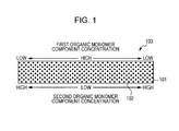
- Fig. 1 is a schematic sectional view of a lens according to the first embodiment.
- the rectangle in Fig. 1 is a schematic section of a lens 103 having the shape of a flat plate, the section being taken in the thickness direction of the lens 103. Accordingly, the central portion of the rectangle in Fig. 1 represents the central portion of the lens 103; and the short sides of the rectangle represent the rim of the lens 103.
- a lens according to the first embodiment includes a transparent member 101 containing a polymer (hereafter, referred to as a "first polymer”) formed from a first organic monomer and a polymer (hereafter, referred to as a "second polymer”) formed from a second organic monomer, the first organic monomer and the second organic monomer having different refractive indices.
- first polymer a polymer formed from a first organic monomer
- second polymer a polymer formed from a second organic monomer
- the central portion of the lens 103 has a high component concentration of the first organic monomer and a low component concentration of the second organic monomer.
- the component concentration of the first organic monomer decreases and the component concentration of the second organic monomer increases. That is, a lens according to the first embodiment has a three-dimensional distribution of the component concentration proportions (concentration proportions) of the first organic monomer and the second organic monomer and hence has a refractive index distribution.
- component concentration denotes the weight concentration of an organic monomer in a transparent member in which the organic monomer has been polymerized.
- the weight concentration of the first polymer is the component concentration of the first organic monomer.
- the quotient calculated by dividing the weight of the component derived from the first organic monomer in the copolymer (excluding a portion of the first organic monomer, the portion being dissociated from the first organic monomer in the polymerization) by the weight of the transparent member is the component concentration of the first organic monomer.
- the lens Due to the three-dimensional distribution of the component concentration proportions of the first organic monomer and the second organic monomer, the lens has a composition proportion distribution of the first polymer and the second polymer or a copolymerization composition proportion distribution of a copolymer formed from the first organic monomer and the second organic monomer.
- the transparent member may be composed of a copolymer formed from three or more organic monomers. In this case, at least two of these organic monomers forming the copolymer have different refractive indices.
- the transparent member may contain two or more copolymers. Such a copolymer may be a random copolymer or a block copolymer.
- the transparent member may be composed of three homopolymers of organic monomers. In this case, at least two of these homopolymers have different refractive indices.
- the transparent member may be composed of copolymers and homopolymers.
- the transparent member when the transparent member is composed of polymers formed from four organic monomers, the transparent member may be composed of a copolymer formed from the four organic monomers, a copolymer formed from three organic monomers selected from the four organic monomers, a copolymer formed from two organic monomers selected from the four organic monomers, and homopolymers formed from the four organic monomers.
- particles 102 are uniformly dispersed in the transparent member 101 in a lens according to the first embodiment.
- the particles 102 have a lower thermal expansion coefficient than the transparent member 101.
- the lens according to the first embodiment has a lower thermal expansion coefficient than the transparent member.
- thermal expansion coefficients in the lens results in a small variation in thermal expansion coefficients in the lens.
- a flat lens composed of a polymer A (thermal expansion coefficient: X) and a polymer B (thermal expansion coefficient: Y (Y ⁇ X)).
- the central portion of the lens is composed of the polymer A.
- the circumferential portion of the lens is composed of the polymer B.
- the area between the central portion and the circumferential portion of the lens is composed of a mixture of the polymers A and B.
- the central portion of the lens has the thermal expansion coefficient X.
- the circumferential portion of the lens has the thermal expansion coefficient Y.
- the area between the central portion and the circumferential portion of the lens probably has a thermal expansion coefficient that is less than X and more than Y.
- the difference in thermal expansion coefficient between the central portion and the circumferential portion of the lens is "X - Y". In such a case, when particles (thermal expansion coefficient:
- the primary particle size of particles according to the first embodiment is desirably 1 nm or more and 50 nm or less.
- the reason for this is as follows.
- the primary particle size of the particles is 1 nm or more, the particles are less likely to agglomerate and the particles are readily dispersed in a transparent member according to the first embodiment.
- the primary particle size of the particles is 50 nm or less, the occurrence of light scattering caused by the particles is reduced and the lens can have a sufficiently high transparency.
- Particles according to the first embodiment desirably have a narrow particle size distribution.
- Particles according to the first embodiment desirably have a spherical shape.
- Non-limiting examples of particles according to the first embodiment include particles composed of titanium oxide (TiO 2 ), titanium hydroxide (Ti(OH) 4 ), zirconium oxide (ZrO 2 ), tantalum oxide (Ta 2 O 5 ), aluminum oxide (Al 2 O 3 ), niobium oxide (Nb 2 O 5 ), tin oxide (SnO 2 ), antimony oxide (Sb 2 O 5 ), zinc oxide (ZnO), silicon oxide (SiO 2 ), indium tin oxide (ITO), indium oxide (In 2 O 3 ), lanthanum oxide (La 2 O 3 ), gadolinium oxide (Gd 2 O 3 ), hafnium oxide (HfO 2 ), erbium oxide (Er 2 O 3 ), neodymium oxide (Nd 2 O 3 ), cerium oxide (CeO 2 ), dysprosium oxide (Dy 2 O 3 ), magnesium oxide (MgO), iron oxide (Fe 2 O 3 ), iron hydroxide (Fe
- the above-listed particles may be used in combination.
- the particles are desirably selected such that the resultant lens can have a high refractive index, a high heat resistance, low light scattering, and the like.
- the surfaces of the particles are desirably chemically modified in the preparation of the particles.
- a treatment such as addition of a dispersing agent is desirably performed.
- particles causing photocatalytic reaction such as titanium oxide particles, to suppress decomposition of a transparent member in areas around the particles by the photocatalytic reaction, if necessary, the particles are desirably treated such that, for example, the surfaces of the particles are coated with a silicon compound or the like.
- the content of such particles with respect to the entire weight of a lens is preferably 1 wt% or more and 99 wt% or less and, more preferably 1 wt% or more and 70 wt% or less.
- the reason for this is as follows. When the content is less than 1 wt%, an advantageous effect of reducing thermal expansion coefficient in the present invention is not sufficiently achieved. When the content is more than 70 wt%, a wide composition distribution of two organic monomers is not achieved and the lens has a narrow refractive index distribution.
- organic monomers according to the first embodiment include radical polymerizable monomers and cationic polymerizable monomers.
- (meth)acryloyl group is a generic name encompassing an acryloyl group and a methacryloyl group.
- (meth)acryl is a generic name encompassing acryl and methacryl.
- (meth)acrylate” is a generic name encompassing acrylate and methacrylate.
- EO denotes ethylene oxide.
- EO-modified compound denotes a compound having an ethylene-oxide-group block structure.
- PO denotes propylene oxide.
- PO-modified compound denotes a compound having a propylene-oxide-group block structure.
- EO/PO-modified compound denotes a compound having both an ethylene-oxide-group block structure and a propylene-oxide-group block structure.
- Radical polymerizable monomers are desirably compounds each having one or more (meth)acryloyl groups.
- Non-limiting examples of the compounds each having a single (meth)acryloyl group include phenoxyethyl (meth)acrylate, phenoxy-2-methylethyl (meth)acrylate, phenoxyethoxyethyl (meth)acrylate, 3-phenoxy-2-hydroxypropyl (meth)acrylate, 2-phenylphenoxyethyl (meth)acrylate, 4-phenylphenoxyethyl (meth)acrylate, 3-(2-phenylphenyl)-2-hydroxypropyl (meth)acrylate, (meth)acrylate of ethylene oxide adduct of p-cumylphenol, 2-bromophenoxyethyl (meth)acrylate, 2,4-dibromophenoxyethyl (meth)acrylate, 2,4,6-tribromophenoxyethyl (meth)acrylate, phenoxy (meth)acrylate modified with several moles of ethylene oxide or propylene oxide, poly(oxyethylene)
- Non-limiting examples of commercially available compounds each having a single (meth)acryloyl group include ARONIX M101, M102, M110, M111, M113, M117, M5700, TO-1317, M120, M150, and M156 (manufactured by TOAGOSEI CO., LTD.); LA, IBXA, 2-MTA, HPA, VISCOAT #150, #155, #158, #190, #192, #193, #220, #2000, #2100, and #2150 (manufactured by OSAKA ORGANIC CHEMICAL INDUSTRY LTD.); LIGHT-ACRYLATE BO-A, EC-A, DMP-A, THF-A, HOP-A, HOA-MPE, HOA-MPL, PO-A, P-200A, NP-4EA, NP-8EA, and Epoxy Ester M-600A (manufactured by Kyoeisha Chemical Co., Ltd.); KAYARAD TC110S, R-5
- Non-limiting examples of the compounds each having two or more (meth)acryloyl groups include trimethylolpropane di(meth)acrylate, trimethylolpropane tri(meth)acrylate, EO-modified trimethylolpropane tri(meth)acrylate, PO-modified trimethylolpropane tri(meth)acrylate, EO/PO-modified trimethylolpropane tri(meth)acrylate, pentaerythritol tri(meth)acrylate, pentaerythritol tetra(meth)acrylate, ethylene glycol di(meth)acrylate, tetraethylene glycol di(meth)acrylate, polyethylene glycol di(meth)acrylate, polypropylene glycol di(meth)acrylate, 1,4-butanediol di(meth)acrylate, 1,6-hexanediol di(meth)acrylate, neopentyl glycol di(meth)
- Non-limiting examples of commercially available compounds each having two or more (meth)acryloyl groups include Yupimer UV SA1002 and SA2007 (manufactured by Mitsubishi Chemical Corporation); VISCOAT #195, #230, #215, #260, #335HP, #295, #300, #360, #700, GPT, and 3PA (manufactured by OSAKA ORGANIC CHEMICAL INDUSTRY LTD.); LIGHT-ACRYLATE 4EG-A, 9EG-A, NP-A, DCP-A, BP-4EA, BP-4PA, TMP-A, PE-3A, PE-4A, and DPE-6A (manufactured by Kyoeisha Chemical Co., Ltd.); KAYARAD PET-30, TMPTA, R-604, DPHA, DPCA-20, -30, -60, -120, HX-620, D-310, and D-330 (manufactured by Nippon Kayaku Co., Ltd.); ARONIX M208, M
- Cationic polymerizable monomers are desirably compounds each having one or more vinyl ether groups, epoxy groups, or oxetanyl groups.
- Non-limiting examples of the compounds each having a single vinyl ether group include methyl vinyl ether, ethyl vinyl ether, propyl vinyl ether, n-butyl vinyl ether, t-butyl vinyl ether, 2-ethylhexyl vinyl ether, n-nonyl vinyl ether, lauryl vinyl ether, cyclohexyl vinyl ether, cyclohexylmethyl vinyl ether, 4-methylcyclohexylmethyl vinyl ether, benzyl vinyl ether, dicyclopentenyl vinyl ether, 2-dicyclopentenoxyethyl vinyl ether, methoxyethyl vinyl ether, ethoxyethyl vinyl ether, butoxyethyl vinyl ether, methoxyethoxyethyl vinyl ether, ethoxyethoxyethyl vinyl ether, methoxypolyethylene glycol vinyl ether, tetrahydrofurfuryl vinyl ether, 2-hydroxyethyl vinyl
- Non-limiting examples of the compounds each having two or more vinyl ether groups include divinyl ethers such as ethylene glycol divinyl ether, diethylene glycol divinyl ether, polyethylene glycol divinyl ether, propylene glycol divinyl ether, butylene glycol divinyl ether, hexanediol divinyl ether, bisphenol A alkylene oxide divinyl ether, and bisphenol F alkylene oxide divinyl ether; and polyfunctional vinyl ethers such as trimethylolethane trivinyl ether, trimethylolpropane trivinyl ether, ditrimethylolpropane tetravinyl ether, glycerin trivinyl ether, pentaerythritol tetravinyl ether, dipentaerythritol pentavinyl ether, dipentaerythritol hexavinyl ether, ethylene oxide adduct of trimethylolprop
- Non-limiting examples of the compounds each having a single epoxy group include phenyl glycidyl ether, p-tert-butylphenyl glycidyl ether, butyl glycidyl ether, 2-ethylhexyl glycidyl ether, allyl glycidyl ether, 1,2-butylene oxide, 1,3-butadiene monooxide, 1,2-epoxydodecane, epichlorohydrin, 1,2-epoxydecane, styrene oxide, cyclohexene oxide, 3-methacryloyloxymethyl cyclohexene oxide, 3-acryloyloxymethyl cyclohexene oxide, and 3-vinyl cyclohexene oxide.
- Non-limiting examples of the compounds each having two or more epoxy groups include bisphenol A diglycidyl ether, bisphenol F diglycidyl ether, bisphenol S diglycidyl ether, brominated bisphenol A diglycidyl ether, brominated bisphenol F diglycidyl ether, brominated bisphenol S diglycidyl ether, epoxy novolac resins, hydrogenated bisphenol A diglycidyl ether, hydrogenated bisphenol F diglycidyl ether, hydrogenated bisphenol S diglycidyl ether, 3,4-epoxycyclohexylmethyl-3',4'-epoxycyclohexane carboxylate, 2-(3,4-epoxycyclohexyl-5,5-spiro-3,4-epoxy)cyclohexane-meth-dioxane, bis(3,4-epoxycyclohexylmethyl) adipate, vinylcyclohexene oxide, 4-vinylepoxycyclohex
- Non-limiting examples of the compounds each having a single oxetanyl group include 3-ethyl-3-hydroxymethyloxetane, 3-(meth)allyloxymethyl-3-ethyloxetane, (3-ethyl-3-oxetanaylmethoxy)methylbenzene, 4-fluoro-[1-(3-ethyl-3-oxetanaylmethoxy)methyl]benzene, 4-methoxy-[1-(3-ethyl-3-oxetanaylmethoxy)methyl]benzene, [1-(3-ethyl-3-oxetanaylmethoxy)ethyl] phenyl ether, isobutoxy methyl(3-ethyl-3-oxetanaylmethyl) ether, isobornyl oxyethyl(3-ethyl-3-oxetanaylmethyl) ether, isobornyl
- Non-limiting examples of the compounds each having two or more oxetanyl groups include polyfunctional oxetanes such as 3,7-bis(3-oxetanayl)-5-oxa-nonane, 3,3'-(1,3-(2-methylenyl)propanediyl bis(oxymethylene))-bis(3-ethyloxetane), 1,4-bis[(3-ethyl-3-oxetanaylmethoxy)methyl]benzene, 1,2-bis[(3-ethyl-3-oxetanaylmethoxy)methyl]ethane, 1,3-bis[(3-ethyl-3-oxetanaylmethoxy)methyl]propane, ethylene glycol bis(3-ethyl-3-oxetanaylmethyl) ether, dicyclopentenyl bis(3-ethyl-3-oxetanaylmethyl) ether, tri
- a method for producing a lens according to an embodiment of the present invention will be described as a second embodiment.
- a method for producing a lens according to the present invention is not restricted to the second embodiment.
- FIG. 2A to 2G illustrate steps of a method for producing a lens according to the second embodiment.
- a casting cell having a surface (irradiation surface) irradiated with radiation is prepared.
- the casting cell is prepared so as to have a gap between two bases 201 at least one of which is transparent to the radiation used by interposing a gasket 202 serving as a spacer between the bases 201.
- the gap is filled with a first radiation polymerizable composition (A) 203 containing a first organic monomer (d) that is polymerizable with radiation, a radiation-sensitive polymerization initiator (c), and particles (e) ( Fig. 2A ).
- a portion of the irradiation surface the casting cell is subsequently irradiated with radiation 205 through a masking member 204 placed on the irradiation surface.
- a portion of the first radiation polymerizable composition (A) 203 in the casting cell is polymerized and turned into a polymer 206 ( Fig. 2B ).
- the polymer formed from the first radiation polymerizable composition (A) is sometimes abbreviated as a first-composition polymer.
- the first-composition polymer in which the particles are uniformly dispersed can be obtained.
- an unpolymerized portion 207 of the first radiation polymerizable composition (A) is removed from the casting cell ( Fig. 2C ).
- the cavity generated by the removal in the casting cell is subsequently filled with a second radiation polymerizable composition (B) 208 containing a second organic monomer (d1) that is polymerizable with radiation and has a refractive index different from that of the first organic monomer (d).
- the second radiation polymerizable composition (B) 208 is brought into contact with the first-composition polymer 206 ( Fig. 2D ).
- the casting cell is left for a predetermined time so that the second radiation polymerizable composition (B) 208 diffuses into the first-composition polymer 206 ( Fig. 2E ).
- the second radiation polymerizable composition (B) having diffused into the first-composition polymer 206, the first-composition polymer 206, and the second radiation polymerizable composition (B) 208 in the casting cell are subsequently cured by irradiation with radiation or heating ( Fig. 2F ).
- the cured product that is to serve as a lens having a refractive index distribution is removed from the casting cell ( Fig. 2G ).
- the cured product is illustrated such that the cured product is constituted by a portion of the first-composition polymer 206 only, a portion of a second-composition polymer 209 formed from the second radiation polymerizable composition (B) only, and a portion that is present between the first-composition polymer 206 and the second-composition polymer 209 and contains both the first-composition polymer 206 and the second-composition polymer 209.
- the portion containing the first-composition polymer 206 and the second-composition polymer 209 has a distribution of the composition proportions of the first-composition polymer 206 and the second-composition polymer 209, which is not illustrated in Figs.
- the copolymer has a distribution of the copolymerization composition proportions.
- the composition proportions in the distribution and the copolymerization composition proportions in the distribution may vary continuously or discontinuously.
- a method for producing a lens according to the second embodiment in which such a diffusion phenomenon is employed a desired lens can be obtained with simple equipment, through a small number of steps, and in a short time.
- a method for producing a lens according to the second embodiment is not restricted to methods employing the diffusion phenomenon.
- the first radiation polymerizable composition (A) contains the radiation-sensitive polymerization initiator (c), the first organic monomer (d), and the particles (e).
- the first radiation polymerizable composition (A) may further contain a photosensitizer (f) and a thermal polymerization initiator (g).
- the particles (e) may be composed of one or more materials selected from the listed materials in the "Particles".
- the radiation-sensitive polymerization initiator (c) is a radiation-sensitive radical generator when the first organic monomer (d) is a radical polymerizable monomer; and the radiation-sensitive polymerization initiator (c) is a radiation-sensitive acid generator when the first organic monomer (d) is a cationic polymerizable monomer.
- the radiation-sensitive radical generator is a compound that causes a chemical reaction upon irradiation with a radiation such as infrared rays, visible light, ultraviolet rays, far ultraviolet rays, X rays, or a charged particle beam (e.g., electron beam) and, as a result of the chemical reaction, radicals are generated, which initiates radical polymerization.
- a radiation such as infrared rays, visible light, ultraviolet rays, far ultraviolet rays, X rays, or a charged particle beam (e.g., electron beam)
- Non-limiting examples of such a compound include: 2,4,5-triarylimidazole dimers that may be substituted such as a 2-(o-chlorophenyl)-4,5-diphenylimidazole dimer, a 2-(o-chlorophenyl)-4,5-di(methoxyphenyl)imidazole dimer, a 2-(o-fluorophenyl)-4,5-diphenylimidazole dimer, and a 2-(o- or p-methoxyphenyl)-4,5-diphenylimidazole dimer; benzophenone derivatives such as benzophenone, N,N'-tetramethyl-4,4'-diaminobenzophenone (Michler's ketone), N,N'-tetraethyl-4,4'-diaminobenzophenone, 4-methoxy-4'-dimethylaminobenzophenone, 4-chlorobenzophenone, 4,4'-d
- Non-limiting examples of commercially available radiation-sensitive radical generators include Irgacure 184, 369, 651, 500, 819, 907, 784, 2959, CGI-1700, -1750, -1850, CG24-61, Darocur 1116, and 1173 (manufactured by Ciba Japan K. K.); Lucirin TPO, LR8893, and LR8970 (manufactured by BASF Japan Ltd.); and EBECRYL P36 (manufactured by UCB S.A.).
- These radiation-sensitive radical generators may be used alone or in combination.
- the radiation-sensitive acid generator is a compound that causes a chemical reaction upon irradiation with a radiation such as infrared rays, visible light, ultraviolet rays, far ultraviolet rays, X rays, or a charged particle beam (e.g., electron beam) and, as a result of the chemical reaction, an acid is generated, which initiates cationic polymerization.
- a radiation such as infrared rays, visible light, ultraviolet rays, far ultraviolet rays, X rays, or a charged particle beam (e.g., electron beam)
- a charged particle beam e.g., electron beam
- Non-limiting examples of such a compound include onium salt compounds, sulfone compounds, sulfonate compounds, sulfonimide compounds, and diazomethane compounds.
- onium salt compounds are desirably used as radiation-sensitive acid generators.
- onium salt compounds include iodonium salts, sulfonium salts, phosphonium salts, diazonium salts, ammonium salts, and pyridinium salts.
- Specific examples of onium salt compounds include bis(4-t-butylphenyl)iodonium perfluoro-n-butanesulfonate, bis(4-t-butylphenyl)iodonium trifluoromethanesulfonate, bis(4-t-butylphenyl)iodonium 2-trifluoromethylbenzenesulfonate, bis(4-t-butylphenyl)iodonium pyrenesulfonate, bis(4-t-butylphenyl)iodonium n-dodecylbenzenesulfonate, bis(4-t-butylphenyl)iodonium p-toluenesulfonate, bis(4-t-but
- Non-limiting examples of sulfone compounds include ⁇ -ketosulfone, ⁇ -sulfonylsulfone, and ⁇ -diazo compounds of ⁇ -ketosulfone and ⁇ -sulfonylsulfone.
- Specific examples of sulfone compounds include phenacylphenyl sulfone, mesitylphenacyl sulfone, bis(phenylsulfonyl)methane, and 4-trisphenacyl sulfone.
- Non-limiting examples of sulfonate compounds include alkyl sulfonates, haloalkyl sulfonates, aryl sulfonates, and iminosulfonates. Specific examples of sulfonate compounds include ⁇ -methylolbenzoin perfluoro-n-butane sulfonate, ⁇ -methylolbenzoin trifluoromethane sulfonate, and ⁇ -methylolbenzoin 2-trifluoromethylbenzene sulfonate.
- Non-limiting examples of sulfonimide compounds include N-(trifluoromethylsulfonyloxy)succinimide, N-(trifluoromethylsulfonyloxy)phthalimide, N-(trifluoromethylsulfonyloxy)diphenylmaleimide, N-(trifluoromethylsulfonyloxy)bicyclo[2.2.1]hept-5-ene-2,3-dicarboxyimide, N-(trifluoromethylsulfonyloxy)-7-oxabicyclo[2.2.1]hept-5-ene-2,3-dicarboxyimide, N-(trifluoromethylsulfonyloxy)bicyclo[2.2.1]heptane-5,6-oxy-2,3-dicarboxyimide, N-(trifluoromethylsulfonyloxy)naphthylimide, N-(10-camphorsulfonyloxy)succinimide, N
- Non-limiting examples of diazomethane compounds include bis(trifluoromethylsulfonyl)diazomethane, bis(cyclohexylsulfonyl)diazomethane, bis(phenylsulfonyl)diazomethane, bis(p-toluenesulfonyl)diazomethane, methylsulfonyl p-toluenesulfonyl diazomethane, (cyclohexylsulfonyl)(1,1-dimethylethylsulfonyl)diazomethane, and bis(1,1-dimethylethylsulfonyl)diazomethane.
- These radiation-sensitive acid generators may be used alone or in combination.
- the mixing percentage of the radiation-sensitive polymerization initiator (c) with respect to the entire amount of the first radiation polymerizable composition (A) is preferably 0.01 wt% or more and 10 wt% or less and more preferably 0.1 wt% or more and 3 wt% or less.
- the mixing percentage is less than 0.01 wt%, there may be cases where the polymerization rate of the first radiation polymerizable composition (A) is low and the reaction efficiency is low.
- the mixing percentage is more than 10 wt%, there may be cases where the cured product of the first radiation polymerizable composition (A) is brittle or the cured product is tinted due to absorption of visible light by the radiation-sensitive acid generator.
- the particles (e) are desirably chemically modified with a surface modifying agent having a functional group that can polymerize with the first organic monomer (d). This is because, in the diffusion of the second radiation polymerizable composition (B), diffusion of the particles (e) is reduced and uniform dispersion of the particles (e) in a lens according to the second embodiment is maintained.
- the functional group that can polymerize with the first organic monomer (d) is desirably a (meth)acryloyl group when the first organic monomer (d) is a radical polymerizable monomer.
- the functional group that can polymerize with the first organic monomer (d) is desirably a vinyl ether group, an epoxy group, or an oxetanyl group when the first organic monomer (d) is a cationic polymerizable monomer.
- the first radiation polymerizable composition (A) desirably contains the photosensitizer (f).
- the photosensitizer (f) is a compound that is excited by absorbing light having a specific wavelength and interacts with the radiation-sensitive polymerization initiator (c).
- Non-limiting examples of the photosensitizer (f) include coumarin derivatives, benzophenone derivatives, thioxanthone derivatives, anthracene derivatives, carbazole derivatives, and perylene derivatives.
- the interaction between the photosensitizer (f) and the radiation-sensitive polymerization initiator (c) is, for example, energy transfer or electron transfer from the photosensitizer (f) being excited to the radiation-sensitive polymerization initiator (c).
- the photosensitizer (f) desirably has a higher molar extinction coefficient with respect to exposure wavelength than the radiation-sensitive polymerization initiator (c).
- the second radiation polymerizable composition (B) contains the second organic monomer (d1) that is polymerizable with radiation and has a refractive index different from that of the first organic monomer (d).
- the second radiation polymerizable composition (B) may further contain particles (e1), a photosensitizer (f1), and a thermal polymerization initiator (g1).
- the first radiation polymerizable composition (A) and the second radiation polymerizable composition (B) are desirably in the form of liquid.
- the first radiation polymerizable composition (A) is desirably in the form of liquid when the first radiation polymerizable composition (A) is charged into and removed from a casting cell. This is because the first radiation polymerizable composition (A) can be readily charged into the casting cell and an unpolymerized portion of the first radiation polymerizable composition (A) can be readily removed from the casting cell.
- the removal of the unpolymerized portion of the first radiation polymerizable composition (A) from the first-composition polymer is less likely to damage the end surfaces of the polymer.
- the first radiation polymerizable composition (A) When the first radiation polymerizable composition (A) is in the form of solid at room temperature under atmospheric pressure, if necessary, the first radiation polymerizable composition (A) may be charged into or removed from a casting cell under heating or pressurization.
- the casting cell is prepared so as to have a gap between two bases at least one of which is transparent to the radiation used by interposing a gasket serving as a spacer between the bases. If necessary, the bases of the casting cell may be fixed with spring clips or the like.
- the first radiation polymerizable composition (A) is charged into the gap provided with the spacer by using a syringe or the like.
- a transparent base is composed of, for example, quartz; glass; a transparent resin such as a silicone resin, a fluorocarbon resin, an acrylic resin, a polycarbonate resin, or polyimide; sapphire; or diamond.
- the syringe needle is desirably left so as to be inserted in the casting cell after the first radiation polymerizable composition (A) is charged into the casting cell.
- the inner surfaces of the casting cell may be spherical surfaces or aspherical surfaces such as flat surfaces and can be selected in accordance with an intended device.
- the inner surfaces of the casting cell are desirably treated with a release agent.
- a treatment with a release agent is performed by applying the release agent such as a fluorocarbon resin, a silicone resin, or a fatty ester by spraying, dipping, spin-coating, or the like and, if necessary, by heating the applied agent.
- Excessive release agent on the casting cell may be removed by cleaning with a solvent or wiping.
- a radiation with which the casting cell is irradiated is selected in accordance with the sensitivity wavelength of the first radiation polymerizable composition (A), and is desirably appropriately selected from ultraviolet rays ranging from about 200 to 400 nm, X rays, electron beams, and the like. Since various photosensitive compounds having sensitivity to ultraviolet rays for the first organic monomer (d) are readily available, a radiation used in the second embodiment is desirably particularly ultraviolet rays.
- a light source radiating ultraviolet rays is, for example, a high-pressure mercury-vapor lamp, an ultrahigh-pressure mercury-vapor lamp, a low-pressure mercury-vapor lamp, a Deep-UV lamp, a carbon-arc lamp, a chemical lamp, a metal halide lamp, a xenon lamp, or the like.
- an ultrahigh-pressure mercury-vapor lamp is desirable.
- the above-listed radiations may be used in combination.
- a radiation is radiated onto the irradiation surface of a casting cell to thereby cure a portion of the first radiation polymerizable composition (A) in the casting cell.
- a portion of the first radiation polymerizable composition (A) in the casting cell is cured by irradiating the first radiation polymerizable composition (A) with the radiation through a masking member on the irradiation surface of the casting cell, or scanning the portion with the radiation in the form of a beam.
- the degree of polymerization of the first radiation polymerizable composition (A) can be controlled by adjusting the dose of the radiation.
- a radiation When a portion of the first radiation polymerizable composition (A) is polymerized, a radiation may be radiated in accordance with a dose distribution.
- a radiation When a radiation is radiated in accordance with a dose distribution, the degree of polymerization of the first radiation polymerizable composition (A) can be controlled and a refractive index distribution can be controlled.
- the second radiation polymerizable composition (B) is readily diffused into the circumferential portion of the first-composition polymer, which is desirable.
- the dose of a radiation radiated onto the irradiation surface of a casting cell desirably increases toward the circumference of the irradiation surface.
- the diffusion behavior of the second radiation polymerizable composition (B) can be controlled by irradiating the first radiation polymerizable composition (A) in accordance with a dose distribution.
- a refractive index distribution profile can be controlled.
- Non-limiting examples of a method of radiating a radiation in accordance with a dose distribution include a method of placing a gray-scale mask having locally different radiation transmittances on the casting cell, a method of moving a masking member during the irradiation with the radiation, and a method of scanning a target portion with the radiation in the form of a beam.
- the degree of polymerization of the first radiation polymerizable composition (A) after radiation polymerization is desirably as less as possible such that, when the unpolymerized portion of the first radiation polymerizable composition (A) in the form of liquid is removed with a syringe needle at the interface between the irradiated portion and the unirradiated portion of the first radiation polymerizable composition (A), the first-composition polymer does not collapse.
- the minimum degree of polymerization with which the shape of the polymer does not collapse is desirable. This is because, the lower the degree of polymerization of the first-composition polymer, the more rapidly the diffusion of the second radiation polymerizable composition (B) proceeds.
- the degree of curing of the polymer of the first radiation polymerizable composition (A) formed by irradiation with a radiation will be described.
- the complex viscosity of the first radiation polymerizable composition (A) is desirably 10 Pa ⁇ s or more and less than 10,000 Pa ⁇ s.
- the complex viscosity is 10 Pa ⁇ s or more
- the unpolymerized portion of the first radiation polymerizable composition (A) in the form of liquid is removed with a syringe needle from a casting cell
- the irradiated portion of the first radiation polymerizable composition (A) that is, the cured portion is less likely to collapse.
- the second radiation polymerizable composition (B) diffuses rapidly in the standing step described below.
- the complex viscosity of the polymer of the first composition (A) is desirably 50 Pa ⁇ s or more and desirably 6,000 Pa ⁇ s or less.
- the complex viscosity can be measured with a dynamic viscoelasticity measurement apparatus (viscoelasticity measurement apparatus MCR-301 manufactured by Anton Paar Japan K.K.).
- the exposure dose of a radiation having a wavelength of 365 nm is preferably 0.01 mJ/cm 2 or more and 1,000,000 mJ/cm 2 or less and, more preferably 0.1 mJ/cm 2 or more and 100,000 mj/cm 2 or less.
- the unpolymerized portion of the first radiation polymerizable composition (A) in the unirradiated portion is removed from the casting cell.
- a syringe needle used for the injection of the first radiation polymerizable composition (A) is left in the casting cell, the unpolymerized portion of the first radiation polymerizable composition (A) is desirably extracted through the syringe needle. If necessary, the unpolymerized portion of the first radiation polymerizable composition (A) may be removed under heating or pressurization.
- the unpolymerized portion of the first radiation polymerizable composition (A) being in contact with the end surfaces of the gel is in the form of liquid and hence is less likely to damage the end surfaces of the gel in the removal of the unpolymerized portion of the first radiation polymerizable composition (A).
- a syringe containing the second radiation polymerizable composition (B) is attached to the syringe needle. Then, the cavity generated by the removal in the casting cell is filled with the second radiation polymerizable composition (B) that is in the form of liquid and has a refractive index different from that of the first radiation polymerizable composition (A). If necessary, the second radiation polymerizable composition (B) may be injected under heating or pressurization.
- the casting cell After the second radiation polymerizable composition (B) is injected, the casting cell is left to stand for a predetermined time. In this standing step, the second radiation polymerizable composition (B) diffuses into the polymerized portion of the first radiation polymerizable composition (A) to provide a concentration proportion distribution of the compositions (A) and (B).
- the lower the degree of polymerization of the first-composition polymer the more rapidly the diffusion proceeds.
- heating, application of an electric field, or application of a magnetic field may be performed or the casting cell may be rotated during the standing step.
- the casting cell In the step of diffusing the second radiation polymerizable composition (B) into the first-composition polymer, the casting cell is desirably heated to a temperature higher than room temperature (23°C).
- the polymerized portion of the first radiation polymerizable composition (A) and the second radiation polymerizable composition (B) are irradiated with a radiation and/or heated to be cured.
- a radiation the above-described radiations may be used.
- the heating may be performed with an existing apparatus such as an oven or a hot plate.
- the compositions (A) and (B) are desirably sufficiently cured.
- the cured product portion of the first radiation polymerizable composition (A) and the cured product portion of the second radiation polymerizable composition (B) desirably have different refractive index wavelength dispersions.
- the cured product is released from the casting cell.
- an intended lens having a composition distribution is provided.
- plastic cured products having model compositions corresponding to the central portion and the circumferential portion of a lens were produced and measured in terms of thermal expansion coefficient.
- a radiation polymerizable composition (A)-1 was prepared that was composed of 75 parts by weight of benzyl methacrylate (manufactured by Kyoeisha Chemical Co., Ltd.) serving as (d), 25 parts by weight of zirconium oxide particles having an average diameter of 7 nm (manufactured by Sumitomo Osaka Cement Co., Ltd.) serving as (e), and 0.1 parts by weight of a photosensitive radical generator (IRGACURE 184 manufactured by Ciba Japan K. K.) serving as (c).
- benzyl methacrylate manufactured by Kyoeisha Chemical Co., Ltd.
- zirconium oxide particles having an average diameter of 7 nm manufactured by Sumitomo Osaka Cement Co., Ltd.
- IRGACURE 184 manufactured by Ciba Japan K. K.
- a radiation polymerizable composition (B)-1 was prepared that was composed of 75 parts by weight of methyl methacrylate (manufactured by Sigma-Aldrich Japan K.K.) serving as (d1), 25 parts by weight of zirconium oxide particles having an average diameter of 7 nm (manufactured by Sumitomo Osaka Cement Co., Ltd.) serving as (e), and 0.1 parts by weight of a photosensitive radical generator (IRGACURE 184 manufactured by Ciba Japan K. K.) serving as (c1).
- methyl methacrylate manufactured by Sigma-Aldrich Japan K.K.
- zirconium oxide particles having an average diameter of 7 nm manufactured by Sumitomo Osaka Cement Co., Ltd.
- IRGACURE 184 manufactured by Ciba Japan K. K.
- Cured products of benzyl methacrylate (polymer: poly(benzyl methacrylate)) have a refractive index of 1.568.
- Cured products of methyl methacrylate (polymer: poly(methyl methacrylate)) have a refractive index of 1.490.
- An UV light source EX250 including a 250 W ultrahigh-pressure mercury-vapor lamp (manufactured by HOYA CANDEO OPTRONICS CORPORATION) was used as a radiation light source.
- a filter that transmits ultraviolet rays and absorbs visible light (UTVAF-50S-36U, manufactured by SIGMA KOKI CO., LTD.) and a frosted dispersion plate (DFSQ1-50C02-800, manufactured by SIGMA KOKI CO., LTD.) were placed between the light source and one of the casting cells.
- the casting cell was irradiated with a radiation from the light source.
- An illuminance at a surface of an optical glass plate of the casting cell, the surface being irradiated with the radiation was 30 mW/cm 2 in terms of wavelength of 365 nm.
- the front surface of the casting cell charged with the radiation polymerizable composition (A)-1 and the whole surfaces of the casting cell charged with the radiation polymerizable composition (B)-1 were each irradiated with the radiation from the optical system for an hour. Then, the optical glass plates were disassembled and cured products that had the shape of a flat plate and were formed from the radiation polymerizable compositions (A)-1 and (B)-1 were obtained.
- the flat-plate cured product composed of a polymer formed from the radiation polymerizable composition (A)-1 and the flat-plate cured product composed of a polymer formed from the radiation polymerizable composition (B)-1 were measured in terms of thermal expansion coefficient in the range of 0°C to 40°C with a thermomechanical analyzer Thermo Plus EVO TMA 8310 manufactured by Rigaku Corporation.
- the cured product composed of the (A)-1 polymer was found to have a thermal expansion coefficient of 58 ppm/°C; and the cured product composed of the (B)-1 polymer was found to have a thermal expansion coefficient of 59 ppm/°C.
- a radiation polymerizable composition (A)-2 was prepared that was composed of 50 parts by weight of benzyl methacrylate (manufactured by Kyoeisha Chemical Co., Ltd.) serving as (d), 50 parts by weight of zirconium oxide particles having an average diameter of 7 nm (manufactured by Sumitomo Osaka Cement Co., Ltd.) serving as (e), and 0.1 parts by weight of a photosensitive radical generator (IRGACURE 184 manufactured by Ciba Japan K. K.) serving as (c).
- benzyl methacrylate manufactured by Kyoeisha Chemical Co., Ltd.
- zirconium oxide particles having an average diameter of 7 nm manufactured by Sumitomo Osaka Cement Co., Ltd.
- IRGACURE 184 manufactured by Ciba Japan K. K.
- a radiation polymerizable composition (B)-2 was prepared that was composed of 50 parts by weight of methyl methacrylate (manufactured by Sigma-Aldrich Japan K.K.) serving as (d1), 50 parts by weight of zirconium oxide particles having an average diameter of 7 nm (manufactured by Sumitomo Osaka Cement Co., Ltd.) serving as (e), and 0.1 parts by weight of a photosensitive radical generator (IRGACURE 184 manufactured by Ciba Japan K. K.) serving as (c1).
- methyl methacrylate manufactured by Sigma-Aldrich Japan K.K.
- zirconium oxide particles having an average diameter of 7 nm manufactured by Sumitomo Osaka Cement Co., Ltd.
- a photosensitive radical generator IRGACURE 184 manufactured by Ciba Japan K. K.
- the flat-plate cured products formed from the radiation polymerizable compositions (A)-2 and (B)-2 were measured in terms of thermal expansion coefficient in the range of 0°C to 40°C as in REFERENCE EXAMPLE 1.
- the cured product composed of the (A)-2 polymer was found to have a thermal expansion coefficient of 53 ppm/°C; and the cured product composed of the (B)-2 polymer was found to have a thermal expansion coefficient of 55 ppm/°C.
- a cured product was formed from 100 parts by weight of methyl methacrylate, analyzed, and found to have a thermal expansion coefficient of 75 ppm/°C.
- a cured product was formed from 100 parts by weight of benzyl methacrylate, analyzed, and found to have a thermal expansion coefficient of 71 ppm/°C. Therefore, from REFERENCE EXAMPLES 1 and 2, it has been demonstrated that, by uniformly dispersing particles of zirconium oxide, the thermal expansion coefficient of a cured product is decreased and, in addition, difference in thermal expansion coefficient between cured products having different proportions of a polymer of an organic monomer is also decreased.
- a radiation polymerizable composition (A)-3 was prepared that was composed of 75 parts by weight of benzyl methacrylate (manufactured by Kyoeisha Chemical Co., Ltd.) serving as (d), 25 parts by weight of zirconium oxide particles having an average diameter of 7 nm (manufactured by Sumitomo Osaka Cement Co., Ltd.) serving as (e), and 0.1 parts by weight of a photosensitive radical generator (IRGACURE 184 manufactured by Ciba Japan K. K.) serving as (c).
- benzyl methacrylate manufactured by Kyoeisha Chemical Co., Ltd.
- zirconium oxide particles having an average diameter of 7 nm manufactured by Sumitomo Osaka Cement Co., Ltd.
- IRGACURE 184 manufactured by Ciba Japan K. K.
- a radiation polymerizable composition (B)-3 was prepared that was composed of 72 parts by weight of tetrafluoropropyl methacrylate (manufactured by OSAKA ORGANIC CHEMICAL INDUSTRY LTD.), 18 parts by weight of methyl methacrylate (manufactured by Sigma-Aldrich Japan K.K.), and 10 parts by weight of trimethylolpropane triacrylate that served as (d1), and 0.1 parts by weight of a photosensitive radical generator (IRGACURE 184 manufactured by Ciba Japan K. K.) serving as (c1).
- a photosensitive radical generator IRGACURE 184 manufactured by Ciba Japan K. K.
- a casting cell filled with the radiation polymerizable composition (A)-3 was prepared as in REFERENCE EXAMPLE 1.
- a 50 mm diameter photomask having a 20 mm diameter circular transparent portion in the central portion thereof was placed as a light-shielding member on the casting cell.
- the casting cell was exposed for 50 seconds through the photomask with an optical system as in REFERENCE EXAMPLE 1.
- the light-shielding material of the photomask was chromium and the base material of the photomask was quartz.
- the transmittance of the light-shielding portion was 0.01% or less and the transmittance of the transparent portion was 98%.
- a columnar gel having a diameter of 20 mm was formed in the central portion of the casting cell.
- An empty disposable syringe was attached to a syringe needle.
- the uncured portion of the radiation polymerizable composition (A)-3 was extracted from the casting cell with the syringe.
- a disposable syringe filled with the radiation polymerizable composition (B)-3 was attached to the syringe needle.
- the radiation polymerizable composition (B)-3 was rapidly injected into the casting cell.
- the casting cell was left in an oven at 80°C for 4 hours.
- the whole surfaces of the casting cell was irradiated for an hour with a light source and an optical system as in REFERENCE EXAMPLE 1. Then, the optical glass plates were disassembled and a flat-plate cured product was obtained.
- the cured product was evaluated in terms of refractive index distribution at a wavelength of 524.3 nm with a ray-tracing refractive-index-distribution measurement apparatus (Index Profile Analyzer: IPA5-C, manufactured by ADVANCED TECHNOLOGIES CO., LTD.). The results are illustrated in Fig. 3 .
- a continuous refractive index distribution in which the maximum value was about 0.095 was measured in a circular area having a diameter of about 20 mm.
- a composition distribution in the irradiation surface of the cured product was observed with an energy dispersive micro x-ray fluorescence spectrometer ⁇ EDX-1300 (manufactured by SHIMADZU CORPORATION) with which ultimate analysis of a 50 ⁇ m diameter area can be performed. Specifically, the intensity of the peak of a fluorescent X-ray (15.85 keV) derived from zirconium atoms was mapped at an interval of 0.2 mm. The results are illustrated in Fig. 4 .
- the volume concentration of zirconium atoms that is, the volume concentration of the zirconium oxide particles (e) is within ⁇ 10% of the average volume concentration of the particles in a circular area having a diameter of about 20 mm. Thus, it has been confirmed that the zirconium oxide particles (e) are uniformly dispersed.
- EXAMPLE 1 has demonstrated that, by a method for producing a gradient-index plastic lens according to the present invention, a gradient-index plastic lens according to the present invention can be produced with simple equipment, through a small number of steps, and in a short time.
- a 50 mm diameter photomask having a 20 mm diameter circular transparent portion in the central portion thereof was prepared as in EXAMPLE 1. Then, the radiation polymerizable composition (A)-3 was exposed to ultraviolet rays with different exposure times as described below.
- the photomask was placed on the central portion of the casting cell.
- the casting cell was irradiated for 25 seconds with a light source and an optical system as in EXAMPLE 1 through the photomask at an illuminance of 30 mW / cm 2 .
- the photomask was placed on the central portion of the casting cell.
- the casting cell was irradiated for 40 seconds with a light source and an optical system as in EXAMPLE 1 through the photomask at an illuminance of 30 mW / cm 2 .
- the photomask was placed on the central portion of the casting cell.
- the casting cell was irradiated for 150 seconds with a light source and an optical system as in EXAMPLE 1 through the photomask at an illuminance of 30 mW/cm 2 .
- the photomask was placed on the central portion of the casting cell.
- the casting cell was irradiated for 200 seconds with a light source and an optical system as in EXAMPLE 1 through the photomask at an illuminance of 30 mW / cm 2 .
- the uncured portions of the radiation polymerizable composition (A)-3 were extracted from the casting cells in MEASUREMENT EXAMPLES 2-1 to 2-4 as in EXAMPLE 1.
- the radiation polymerizable composition (B)-3 was rapidly injected into the casting cells in MEASUREMENT EXAMPLES 2-2 to 2-4 as in EXAMPLE 1.
- the relationship between exposure time of the radiation polymerizable composition (A)-3 to ultraviolet rays and complex viscosity of the radiation polymerizable composition (A)-3 having been exposed to ultraviolet rays was examined with a dynamic viscoelasticity measurement apparatus having an ultraviolet-ray radiation mechanism (MCR-301 manufactured by Anton Paar Japan K.K.).
- the ultraviolet rays were radiated at an illuminance of 30 mW/cm 2 in terms of a wavelength of 365 nm.
- the relationship between exposure time and complex viscosity is illustrated in Fig. 9 .
- a radiation polymerizable composition (C)-1 was prepared that was composed of 50 parts by weight of benzyl methacrylate (manufactured by Kyoeisha Chemical Co., Ltd.), 50 parts by weight of zirconium oxide particles having an average diameter of 7 nm (manufactured by Sumitomo Osaka Cement Co., Ltd.), and 0.1 parts by weight of a photosensitive radical generator (IRGACURE 184 manufactured by Ciba Japan K. K.).
- a radiation polymerizable composition (C)-2 was prepared that was composed of 60 parts by weight of benzyl methacrylate (manufactured by Kyoeisha Chemical Co., Ltd.), 40 parts by weight of zirconium oxide particles having an average diameter of 7 nm (manufactured by Sumitomo Osaka Cement Co., Ltd.), and 0.1 parts by weight of a photosensitive radical generator (IRGACURE 184 manufactured by Ciba Japan K. K.).
- a radiation polymerizable composition (C)-3 was prepared that was composed of 75 parts by weight of benzyl methacrylate (manufactured by Kyoeisha Chemical Co., Ltd.), 25 parts by weight of zirconium oxide particles having an average diameter of 7 nm (manufactured by Sumitomo Osaka Cement Co., Ltd.), and 0.1 parts by weight of a photosensitive radical generator (IRGACURE 184 manufactured by Ciba Japan K. K.).
- a radiation polymerizable composition (C)-4 was prepared that was composed of 100 parts by weight of benzyl methacrylate (manufactured by Kyoeisha Chemical Co., Ltd.) and 0.1 parts by weight of a photosensitive radical generator (IRGACURE 184 manufactured by Ciba Japan K. K.).
- the flat-plate cured products formed from the radiation polymerizable compositions (C)-1 to (C)-4 were measured in terms of thermal expansion coefficient in the range of 0°C to 40°C as in REFERENCE EXAMPLE 1; as a result, the thermal expansion coefficients were respectively found to be 53, 54, 58, and 71 ppm/°C.
- a radiation polymerizable composition (C)-5 was prepared that was composed of 90 parts by weight of benzyl methacrylate (manufactured by Kyoeisha Chemical Co., Ltd.), 10 parts by weight of trimethylolpropane triacrylate (manufactured by Sigma-Aldrich Japan K.K.), and 0.1 parts by weight of a photosensitive radical generator (IRGACURE 184 manufactured by Ciba Japan K. K.).
- a radiation polymerizable composition (C)-6 was prepared that was composed of 90 parts by weight of methyl methacrylate (manufactured by Sigma-Aldrich Japan K.K.), and 10 parts by weight of trimethylolpropane triacrylate (manufactured by Sigma-Aldrich Japan K.K.), and 0.1 parts by weight of a photosensitive radical generator (IRGACURE 184 manufactured by Ciba Japan K. K.).
- the flat-plate cured products formed from the radiation polymerizable compositions (C)-5 and (C)-6 were measured in terms of thermal expansion coefficient in the range of 0°C to 40°C as in REFERENCE EXAMPLE 1; as a result, the thermal expansion coefficients were respectively found to be 68 and 66 ppm/°C. Compared with plastic lenses containing the particles in REFERENCE EXAMPLES 1 and 2, the thermal expansion coefficients were large.
- the present invention can be applied to various optical systems such as cameras, optical-fiber image-forming systems, copiers, and pickup optical systems for compact discs.
Landscapes
- Physics & Mathematics (AREA)
- General Physics & Mathematics (AREA)
- Optics & Photonics (AREA)
- Engineering & Computer Science (AREA)
- Health & Medical Sciences (AREA)
- Manufacturing & Machinery (AREA)
- Ophthalmology & Optometry (AREA)
- Mechanical Engineering (AREA)
- Polymerisation Methods In General (AREA)
- Casting Or Compression Moulding Of Plastics Or The Like (AREA)
Applications Claiming Priority (1)
| Application Number | Priority Date | Filing Date | Title |
|---|---|---|---|
| JP2010086188 | 2010-04-02 |
Publications (1)
| Publication Number | Publication Date |
|---|---|
| EP2372405A1 true EP2372405A1 (de) | 2011-10-05 |
Family
ID=44212035
Family Applications (1)
| Application Number | Title | Priority Date | Filing Date |
|---|---|---|---|
| EP11002266A Withdrawn EP2372405A1 (de) | 2010-04-02 | 2011-03-18 | Linse und Verfahren zur Linsenherstellung |
Country Status (4)
| Country | Link |
|---|---|
| US (1) | US8582210B2 (de) |
| EP (1) | EP2372405A1 (de) |
| JP (1) | JP2011227466A (de) |
| CN (1) | CN102213779B (de) |
Families Citing this family (2)
| Publication number | Priority date | Publication date | Assignee | Title |
|---|---|---|---|---|
| US9274344B2 (en) * | 2013-07-15 | 2016-03-01 | The Boeing Company | Method for extracting optical energy from an optical beam |
| CN106142446B (zh) * | 2015-03-31 | 2019-03-08 | 法国圣戈班玻璃公司 | 注塑件及其形成方法、包边结构以及车窗 |
Citations (8)
| Publication number | Priority date | Publication date | Assignee | Title |
|---|---|---|---|---|
| JPS5971830A (ja) * | 1982-10-18 | 1984-04-23 | Nippon Sheet Glass Co Ltd | 屈折率分布型レンズ体の製造方法 |
| JPS6173101A (ja) * | 1984-09-19 | 1986-04-15 | Toray Ind Inc | 高屈折率プラスチツクレンズ |
| JPH08244130A (ja) | 1995-02-27 | 1996-09-24 | Essilor Internatl (Cie Gen Opt) | 屈折率勾配のある透明物品の製造方法 |
| US6236493B1 (en) * | 1996-04-04 | 2001-05-22 | Institut für Neue Materialien Gemeinnützige GmbH | Optical components with a graded-index structure, and method of manufacturing such components |
| US20030174994A1 (en) * | 2002-02-19 | 2003-09-18 | Garito Anthony F. | Thermal polymer nanocomposites |
| US20060052547A1 (en) * | 2004-09-07 | 2006-03-09 | Jagdish Jethmalani | Monomers and polymers for optical elements |
| US20080081264A1 (en) * | 2004-12-20 | 2008-04-03 | Epg (Engineered Nanoproducts Germany) Ag | Optical Components Made From An Inorganic/Organic Hybrid Material For The Production Of Refractive Index Gradient Layers With Rapid Kinetics And Method For The Production Thereof |
| US20080200582A1 (en) * | 2007-02-20 | 2008-08-21 | Liliana Craciun | High refractive index monomers, compositions and uses thereof |
Family Cites Families (10)
| Publication number | Priority date | Publication date | Assignee | Title |
|---|---|---|---|---|
| JPH05288901A (ja) * | 1992-04-10 | 1993-11-05 | Yasuhiro Koike | 屈折率勾配を有するプラスチックレンズの製造方法 |
| US6599631B2 (en) * | 2001-01-26 | 2003-07-29 | Nanogram Corporation | Polymer-inorganic particle composites |
| JP2000318057A (ja) * | 1999-05-13 | 2000-11-21 | Keiogijuku | 屈折率分布型プラスチックレンズの製造方法 |
| DE10200648A1 (de) * | 2002-01-10 | 2003-07-24 | Inst Neue Mat Gemein Gmbh | Verfahren zur Herstellung Optischer Elemente mit Gradientenstruktur |
| JP2006106324A (ja) | 2004-10-05 | 2006-04-20 | Nippon Sheet Glass Co Ltd | 屈折率分布型ロッドレンズ、およびその製造方法 |
| CN1828338B (zh) | 2005-02-28 | 2010-08-25 | 鸿富锦精密工业(深圳)有限公司 | 透镜 |
| JP5268240B2 (ja) * | 2005-10-03 | 2013-08-21 | キヤノン株式会社 | 光学用複合材料及び光学素子 |
| JP2009073166A (ja) * | 2007-08-31 | 2009-04-09 | Fujifilm Corp | 光学部材の成形方法及び成形装置ならびに光学部材 |
| FR2920426B1 (fr) | 2007-09-03 | 2011-05-06 | Saint Gobain | Substrat en verre a gradient d'indice de refraction et procede de fabrication |
| DE102008064168A1 (de) * | 2008-12-22 | 2010-06-24 | Leibniz-Institut Für Neue Materialien Gemeinnützige Gmbh | Verfahren und Zusammensetzung zur Herstellung optischer Elemente mit Gradientenstruktur |
-
2011
- 2011-03-07 JP JP2011049145A patent/JP2011227466A/ja active Pending
- 2011-03-18 EP EP11002266A patent/EP2372405A1/de not_active Withdrawn
- 2011-03-31 US US13/077,759 patent/US8582210B2/en not_active Expired - Fee Related
- 2011-04-02 CN CN201110087240.6A patent/CN102213779B/zh not_active Expired - Fee Related
Patent Citations (8)
| Publication number | Priority date | Publication date | Assignee | Title |
|---|---|---|---|---|
| JPS5971830A (ja) * | 1982-10-18 | 1984-04-23 | Nippon Sheet Glass Co Ltd | 屈折率分布型レンズ体の製造方法 |
| JPS6173101A (ja) * | 1984-09-19 | 1986-04-15 | Toray Ind Inc | 高屈折率プラスチツクレンズ |
| JPH08244130A (ja) | 1995-02-27 | 1996-09-24 | Essilor Internatl (Cie Gen Opt) | 屈折率勾配のある透明物品の製造方法 |
| US6236493B1 (en) * | 1996-04-04 | 2001-05-22 | Institut für Neue Materialien Gemeinnützige GmbH | Optical components with a graded-index structure, and method of manufacturing such components |
| US20030174994A1 (en) * | 2002-02-19 | 2003-09-18 | Garito Anthony F. | Thermal polymer nanocomposites |
| US20060052547A1 (en) * | 2004-09-07 | 2006-03-09 | Jagdish Jethmalani | Monomers and polymers for optical elements |
| US20080081264A1 (en) * | 2004-12-20 | 2008-04-03 | Epg (Engineered Nanoproducts Germany) Ag | Optical Components Made From An Inorganic/Organic Hybrid Material For The Production Of Refractive Index Gradient Layers With Rapid Kinetics And Method For The Production Thereof |
| US20080200582A1 (en) * | 2007-02-20 | 2008-08-21 | Liliana Craciun | High refractive index monomers, compositions and uses thereof |
Non-Patent Citations (1)
| Title |
|---|
| KOIKE Y ET AL: "PLASTIC AXIAL GRADIENT-INDEX LENS", APPLIED OPTICS, OPTICAL SOCIETY OF AMERICA, vol. 24, no. 24, 1 December 1985 (1985-12-01), pages 4321 - 4325, XP002040908, ISSN: 0003-6935, DOI: 10.1364/AO.24.004321 * |
Also Published As
| Publication number | Publication date |
|---|---|
| US20110242672A1 (en) | 2011-10-06 |
| CN102213779A (zh) | 2011-10-12 |
| US8582210B2 (en) | 2013-11-12 |
| JP2011227466A (ja) | 2011-11-10 |
| CN102213779B (zh) | 2014-03-26 |
Similar Documents
| Publication | Publication Date | Title |
|---|---|---|
| US9541826B2 (en) | Photocurable composition and method of manufacturing film using the composition | |
| KR101655001B1 (ko) | 막 형성 방법 | |
| KR101735228B1 (ko) | 임프린트 방법 및 임프린트용 경화성 조성물 | |
| US20120164395A1 (en) | Manufacturing method for plastic member and plastic member | |
| US9961776B2 (en) | Method of producing cured product and method of forming pattern | |
| US10472445B2 (en) | Photocurable composition and method for manufacturing film | |
| US8802570B2 (en) | Pattern forming method | |
| US8582210B2 (en) | Lens and method for producing lens | |
| US8945439B2 (en) | Method for manufacturing lens, apparatus for manufacturing lens, and method for manufacturing optical apparatus | |
| JP5623190B2 (ja) | プラスチックレンズの製造方法およびプラスチックレンズ | |
| JP5665351B2 (ja) | 光学部品の製造方法 | |
| US9308552B2 (en) | Curable composition and method of forming pattern |
Legal Events
| Date | Code | Title | Description |
|---|---|---|---|
| PUAI | Public reference made under article 153(3) epc to a published international application that has entered the european phase |
Free format text: ORIGINAL CODE: 0009012 |
|
| AK | Designated contracting states |
Kind code of ref document: A1 Designated state(s): AL AT BE BG CH CY CZ DE DK EE ES FI FR GB GR HR HU IE IS IT LI LT LU LV MC MK MT NL NO PL PT RO RS SE SI SK SM TR |
|
| AX | Request for extension of the european patent |
Extension state: BA ME |
|
| 17P | Request for examination filed |
Effective date: 20120330 |
|
| 17Q | First examination report despatched |
Effective date: 20160226 |
|
| STAA | Information on the status of an ep patent application or granted ep patent |
Free format text: STATUS: THE APPLICATION HAS BEEN WITHDRAWN |
|
| 18W | Application withdrawn |
Effective date: 20160524 |