EP2374939A2 - Dispositif de déclenchement commandé d'avalanches - Google Patents
Dispositif de déclenchement commandé d'avalanches Download PDFInfo
- Publication number
- EP2374939A2 EP2374939A2 EP20110160841 EP11160841A EP2374939A2 EP 2374939 A2 EP2374939 A2 EP 2374939A2 EP 20110160841 EP20110160841 EP 20110160841 EP 11160841 A EP11160841 A EP 11160841A EP 2374939 A2 EP2374939 A2 EP 2374939A2
- Authority
- EP
- European Patent Office
- Prior art keywords
- lifting plate
- plate
- lifting
- pivot axis
- snow
- Prior art date
- Legal status (The legal status is an assumption and is not a legal conclusion. Google has not performed a legal analysis and makes no representation as to the accuracy of the status listed.)
- Withdrawn
Links
- 238000000034 method Methods 0.000 claims abstract description 5
- 238000009825 accumulation Methods 0.000 claims description 3
- 238000003860 storage Methods 0.000 claims description 3
- 230000001960 triggered effect Effects 0.000 description 7
- 238000005520 cutting process Methods 0.000 description 5
- IJGRMHOSHXDMSA-UHFFFAOYSA-N Atomic nitrogen Chemical compound N#N IJGRMHOSHXDMSA-UHFFFAOYSA-N 0.000 description 4
- 230000006835 compression Effects 0.000 description 4
- 238000007906 compression Methods 0.000 description 4
- 238000006073 displacement reaction Methods 0.000 description 3
- 239000000725 suspension Substances 0.000 description 3
- 230000035508 accumulation Effects 0.000 description 2
- 230000008901 benefit Effects 0.000 description 2
- 230000015572 biosynthetic process Effects 0.000 description 2
- 230000000694 effects Effects 0.000 description 2
- 229910052757 nitrogen Inorganic materials 0.000 description 2
- 230000000284 resting effect Effects 0.000 description 2
- 244000025254 Cannabis sativa Species 0.000 description 1
- 229910000831 Steel Inorganic materials 0.000 description 1
- 230000009471 action Effects 0.000 description 1
- 230000002411 adverse Effects 0.000 description 1
- 238000010276 construction Methods 0.000 description 1
- 238000010586 diagram Methods 0.000 description 1
- 239000007789 gas Substances 0.000 description 1
- 210000003127 knee Anatomy 0.000 description 1
- 238000011068 loading method Methods 0.000 description 1
- 210000000056 organ Anatomy 0.000 description 1
- 230000036316 preload Effects 0.000 description 1
- 230000008569 process Effects 0.000 description 1
- 238000005096 rolling process Methods 0.000 description 1
- 230000007480 spreading Effects 0.000 description 1
- 238000003892 spreading Methods 0.000 description 1
- 239000010959 steel Substances 0.000 description 1
Images


Classifications
-
- E—FIXED CONSTRUCTIONS
- E01—CONSTRUCTION OF ROADS, RAILWAYS, OR BRIDGES
- E01F—ADDITIONAL WORK, SUCH AS EQUIPPING ROADS OR THE CONSTRUCTION OF PLATFORMS, HELICOPTER LANDING STAGES, SIGNS, SNOW FENCES, OR THE LIKE
- E01F7/00—Devices affording protection against snow, sand drifts, side-wind effects, snowslides, avalanches or falling rocks; Anti-dazzle arrangements ; Sight-screens for roads, e.g. to mask accident site
- E01F7/04—Devices affording protection against snowslides, avalanches or falling rocks, e.g. avalanche preventing structures, galleries
Definitions
- the invention relates to a device for the controlled triggering of avalanches, in which a lifting plate is pivotally mounted on a base plate resting on the base plate, which is pivotable by means of a lifting device swung up and abruptly downwards, wherein on the lifting plate lateral cantilevers are attached.
- the lateral cantilever plates are substantially fixedly connected to the lifting plate and serve to provide a wider area for catching snow, which then jerkily releases the snow on a wider line in order to trigger an avalanche accordingly.
- the triggering due to the low snow depth is not reliable, since the dropped in one place amount of snow is not sufficient to achieve the appropriate triggering of the avalanche.
- the invention is based on the object to improve a device of the type mentioned so that even at lower snow depths the critical amount for the triggering of snow is achieved.
- this object is achieved in that the lateral cantilevers are pivotally mounted on the lifting plate, wherein means are provided for lifting the cantilever plates in relation to the lifting plate between the lifting plate and cantilevers.
- the means for pivoting the cantilever plates by hydraulic lifting cylinder formed, whereby a simple application without a large number of mechanical parts is achieved.
- screw spindles or worm gears could be used instead of hydraulic lifting cylinders.
- the lateral cantilevers can each be executed in two parts, wherein the two parts are connected to one another parallel to the pivot axis on the lifting plate extending further pivot axis. This ensures that the active surface of the lateral cantilevers can be reduced laterally when z. B. due to high amounts of snow for lifting the lifting plate and the associated cantilevers too much effort would be needed.
- the two parts of each cantilever plate can be stretched by a spring in its extended position, which ensures that the extended position, so that the surfaces of both parts of the cantilever plates lie in one plane, is present as a basic position.
- the two parts of the cantilevers can be locked in the extended position by means of bars, which ensures that when the Cantilever plates are swung up to deposit the amount of snow thereon on the central lifting plate, the entire cantilever plates are swung up and the entire amount of snow is just deposited on the lifting plate.
- This further flap can be pivoted downwardly during pivoting down of the lifting plate from the swung-up position in a plane with the lifting plate, whereby the two movements, namely sudden downward pivoting of the lifting plate and folding the other flap for the purpose of unloading the amount of snow can be adjusted accordingly.
- the device for pivoting the further plate may be coupled to the lifting and triggering device of the lifting plate, which then, when the downward pivoting of the lifting plate is triggered, at the same time the further flap is folded on the downhill edge of the lifting plate.
- the lifting plate may be divided parallel to the pivot axis, where appropriate, omitting the lateral cantilevers, the two parts hinged together and kind of a toggle lever by pulling up the joint connecting the two parts be raised.
- This allows the snow located on the mountain-side raised part to be shifted slightly uphill, whereby the part of the lifting plate facing away from the valley, that is, the part facing away from the pivot axis deposits the snow first at the valley-side edge, wherein the jerky depression the lifting plate to the mountain-side pivot axis stretching the toggle lever takes place, which causes the one hand, the discarding the mountain side pent-up mass of snow and on the other hand, the downhill pushing the snow located in front of the valley end, the two masses united by the sudden downward movement make the avalanche release.
- the free end of the pivot axis of the lifting plate facing away from the part may be performed at approximately in the fall line of the slope rails, whereby a precise pulling up of the two parts and a guided downward folding of the lifting plate is possible.
- the pivot axis of the lifting plate can be performed on the rails for the valley-side folding down the lifting plate. It is thus initially moved when triggering the downward movement of the lifting plate, the entire toggle-like raised lifting plate downwards, so there is a higher impulse on the downhill snow mass.
- a particularly simple control of this Movement can be provided for moving the lifting plate along the rails a cable or a screw.
- a further plate-like part can be hinged at the free end of the pivot axis of the lifting plate, wherein the free end of the pivot axis of the lifting plate facing away from the part by means of push rods of a push plate or the like is guided and wherein the further plate-like part is guided with its free edge directly to the rails.
- control, drive and / or storage devices for print media or energy can be arranged in a separate from the lifting housing or housing part. This also ensures that snow accumulations in the lee of the device due to wind loadings are avoided. Such snow accumulations can hinder the sudden downward movement of the lifting plate in a device with lateral cantilevers under adverse circumstances.
- a fixable by means of a cable pendulum support can be provided for fixing the lifting plate in the raised position, wherein the cable is provided with a freewheel device having winch. It therefore needs to trigger the downward movement of the lifting plate, only the brake of the cable to be solved, so this releases the pendulum support and thus lifting plate due to the freewheel device.
- a collapsible cover for closing the gap between the two plates can be arranged between the base plate and the lifting plate. This is particularly indicated when the lifting plate is lifted as a precaution already at the first snowfall, in order to be able to be used quickly to trigger basic avalanches can.
- the lifting plate can already be raised before a heavy snowfall, after which, after accumulating a corresponding amount of snow, the Triggering of the lifting plate is made to Inizleiter the avalanche.
- FIG. 1 denotes a lifting plate, which on a base plate 2 via a pivot axis 20 arranged on the side ( Fig. 5 ) is articulated.
- This lifting plate 1 is as out Fig. 5 can be lifted via lift pad 21, wherein it is held in the raised position by means of a bell crank 22.
- This toggle lever 22, the course of movement is shown in phantom, also serves as a triggering device for the sudden downward folding of the lifting plate 1 to the effect that in Fig. 5 reproduced position of the toggle lever 22 in the dash-dotted reproduced position is transferred.
- the pivot point 23 of the toggle lever is brought into the resting on the base plate 2 position (see dash-dotted representation).
- the entire device is anchored via a suspension 24 on the mountain.
- a lifting device 8 which is presently designed as a hydraulic cylinder is harnessschwenk- and lowered.
- the downward pivoted basic position is in Fig. 1 and the elevated position in Fig. 3 played.
- the lateral cantilevers consist of two parts, namely the part 3 which is mounted directly on the lifting plate 1 via the shaft 5 and an outer part 4 of the cantilever plate which is articulated on the part 3 via a pivot axis 6.
- the lifting device 8 acts on the lifting plate 1 via a pivot point 10 and on the lateral cantilever on the pivot axis 6 between the two parts 3 and 4 of the further cantilever.
- the two parts 3, 4 of the further cantilever plate are via a spring 18 in its extended position (see Fig. 4 ) biased and fixed in this position by means of a lock 17 against each other.
- Fig. 6 is the mutual position of the two parts 3, 4 at along the pivoting circle 15 downwardly pivoted outer 4 of the side cantilevers 3, 4 reproduced.
- the lock 17 is not shown in detail.
- the lifting plate 1 When operating the device, the lifting plate 1 is first lowered to the base plate 2, wherein in the snow-free months in the mountains, the parts 3, 4 of the lateral cantilevers in the in Fig. 2 reproduced position, whereby the triggering systems remain largely unremarkable in the landscape. Also, a lower susceptibility of weather conditions, especially storms is achieved.
- the pivot axis 20th is provided opposite edge, which can be set up or folded over a lifting device 26.
- the system When operating the system during months of snowfall, the system is in the in Fig. 1 reproduced position ready, with the two parts 3, 4 of the outer cantilevers are in their extended position to catch falling snow, wherein in Fig. 1 the snow thickness is marked with 13 at low snowfall. If below the device according to the invention already a snow slope with unstable snow layer is present, then at this low snow depth 13, the folding up of the outer cantilevers 3, 4 according to Fig. 3 initiated, whereby the snow depth on the base plate 1, the 14 designated thickness attained. In this position then the lifting plate, as in Fig. 5 shown, folded up by means of the lifting pad 21 and fixed by the extended toggle lever 22 in this position.
- the flap 25 By the flap 25, the amount of snow on the lifting plate 1 is held until the flap is released by loosening the lifting device 26 and a complete unloading of the present on the lifting plate 1 amount of snow.
- This lifting device 26 is coupled in a manner not shown with the triggering device for the toggle lever 22 to the effect that when triggering the downward movement of the lifting plate 1 by displacement of the pivot point 23 of the toggle lever 26 and the lifting device 26 is triggered and thus when falling down the lifting plate 1, the amount of snow barrier-free the flap 25 can be done away on the underlying snow mass.
- Fig. 5 The intended for the operation of the device nitrogen steel bottles or drive and control members can, as in Fig. 5 and the following indicated to be housed in a separate supply part 9, whereby the overall height of the entire system can be made extremely low (see also Fig. 8 , from which it can be seen how flat the actual triggering device can be achieved).
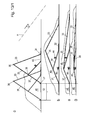
- Fig. 7 and 8th is intended to Hochschwenkung the lateral cantilevers, ropes 27, 27 'via a pylon 28 and on this rollers 29 to be guided to actuators 30, 30', these two actuators are independently controllable.
- traction members 31 To fix the pylon 28 at the top of the lifting plate 1 traction members 31 are provided.
- the traction cables 27, 27 ' engage in this case directly on the lifting plate 1 pivotally mounted part 3 of the cantilevers 3, 4, whereby the entire cantilevers are swung up by the traction cables.
- the structure of the cantilever plates corresponds to those of the above-described embodiment.
- the actuators 30, 30 ' are independently controllable, which causes the cantilever plates can be set up individually, making it possible depending on the wind direction to use the wings as a "snow fence", whereby it can be achieved that in addition very large Snow shedding masses are deposited on the lifting plate 1.
- the above training additionally includes an actuator 49 for a cutting cable 46, which is fastened with its free ends laterally outward on the terrain and which can be tightened by lifting the lifting plate 1 in the release position by means of the actuator 49.
- This cutting cable 46 which intersects the side of the snow masses according to the invention by the high tension thus widening the demolition area after triggering the avalanche, d. h., That the avalanches are triggered not only selectively, but over a corresponding area which can be up to 20 or 30 m.
- the raising of the lifting plate 1 is again via a lifting pad 21, wherein the lifting plate is fixed in the raised position over the knee lever spread 22.
- a flap 25 is provided which can be set up or relocated by means of its own lifting device 26 as needed.
- the execution after the Fig. 11-13 has a lift-up lifting plate, which is formed of three parts, namely the mountain side pivotally mounted part 33, a connected to this part 33 middle part 35 and on this part 35 on the valley side then another part 37, wherein the middle part 35 on the mountain-side part 33rd via a pivot joint 36 and the valley-side part 37 is mounted on the central part 35 via a pivot joint 38. All three parts have lateral cantilevers 41 and 42 and 43 respectively.
- the entire system is mounted on guide rails 32 on the ground, wherein the mountain-side part of the lifting plate 33 is pivotally connected via rollers 34 to the guide rails 33 and slidably guided along rails 32.
- the middle part 35 which is connected via a hinge 38 with the valley-side plate 37, which is guided with its free tal remedyen end over rollers 47 on the rails 32, in turn is guided over a thrust plate 39, which at one end about the pivot axis 38 to the joint between the middle plate 35 and the valley-side plate 37 engages and the other end is guided over rollers 40 also on the rails 32.
- the thrust plate 39 is provided with a compression spring 44, which triggers the pivoting of the central part 35 about the hinge 38 with respect to the thrust plate.
- Fig. 13/1 and 13/2 is the side of the horizontal with "H" drawn to document the position of the device in the field.
- the drive and supply organs housed in a separate part 9 are.
- a photovoltaic system 61, a small compressor 62, a radio 63 and a backup battery 64 are provided. If compressed air bottles and the like are additionally required for the inflation of the lifting cushion, then these are likewise to be accommodated in this supply part 9.
- the said embodiment according to Fig. 14 to 16 again has a lifting table 1, the like Fig. 16 it can be seen laterally project over the entire system, so as to achieve a correspondingly large area.
- the control and release of the lifting table is carried out by means of cables, which spread lever (50) set up, which are guided by carriages on guide rails 52.
- the cables are operated by cable winches 53 and 54.
- the zugenseigen traction cables 55 are defined by pulleys 56 and 56 'on the winches 53 and 54 with the ends.
- the lifting pad 21 is supported on the one hand on the ground and on the other hand on a pressure shell 57, which is provided on the underside of the lifting plate 1.
- This pressure body 57 has transverse bars 58 and 59 which project laterally and support the lateral areas of the lifting plate 1.
- the lifting plate On the upper side, the lifting plate has a covering 60, which may have artificial grass or the like, in order to be able to optically adapt the device to the surrounding terrain in those times when there is no snow.
- the lifting pad 21 is filled either by means of the compressor or in a manner not shown by means of compressed air cylinders or nitrogen bottles, after which the device in the in Fig. 15 reproduced position. With “H" horizontal is drawn again.
- the carriage 51 is moved downwards by means of the tension cables until the spread position is achieved in the manner shown.
- the lifting pad 21 is first emptied, after which, when the winches 53, 54 are released, the lifting plate 1 can be folded downwards.
- the cutting cable 46 that is mounted in guides 46 'at the front end of the lifting plate 1 is stretched, so that already achieved above cutting the snow layer is reached.
- a lifting table 1 pivotally mounted on an axis 20 on a base plate, wherein the individual actuating devices are housed again in the supply part 9.
- a small lifting bag 71 is provided, which initiates the lifting of the lifting plate one.
- the further raising of the lifting plate 1 is then carried out by spreading 65 which with one end is hinged to a pulling member and the other end to a pivot joint on the underside of the lifting plate 1.
- the tension member can either, as in Fig. 17 shown, the end of a piston rod 68 of a piston-cylinder unit 66 which engages a carriage 67, on which the expansion lever 65 is pivotally mounted about an axis 69.
- a collapsible bellows 74 is provided, which prevents laterally into the construction snow can be blown in, which then hinder a downward pivoting of the lifting plate 1.
- the training according to Fig. 18 corresponds to that of Fig. 17 , with the difference that instead of the piston-cylinder unit 66, 68 acts on the carriage 67, a cable 72 which is actuated via a cable winch 73.
- the traction cable 72 is guided in a supply channel 65, which connects the supply part 9 with the triggering device, safely.
- the lifting movement of the lifting plate 1 is initiated by the small lifting bag 71, after which the raising of the expansion lever 65 takes place by rolling the traction cable 72 on the winch 73.
- To trigger the winch 73 is released, which allows a freewheeling rapid downward pivoting of the lifting plate 1.
- Fig. 18 is marked with 13 a low amount of snow and 14 then a quantity of snow as can be achieved by folding up in these positions not reproduced lateral cantilevers.
- the formation of the cantilevers in terms of suspension and actuation may be made according to any of the embodiments set out above.
Landscapes
- Engineering & Computer Science (AREA)
- Architecture (AREA)
- Civil Engineering (AREA)
- Structural Engineering (AREA)
- Devices Affording Protection Of Roads Or Walls For Sound Insulation (AREA)
Applications Claiming Priority (4)
| Application Number | Priority Date | Filing Date | Title |
|---|---|---|---|
| AT5422010 | 2010-04-06 | ||
| AT13412010 | 2010-08-09 | ||
| AT17242010 | 2010-10-18 | ||
| AT2742011 | 2011-03-01 |
Publications (1)
| Publication Number | Publication Date |
|---|---|
| EP2374939A2 true EP2374939A2 (fr) | 2011-10-12 |
Family
ID=44262977
Family Applications (1)
| Application Number | Title | Priority Date | Filing Date |
|---|---|---|---|
| EP20110160841 Withdrawn EP2374939A2 (fr) | 2010-04-06 | 2011-04-01 | Dispositif de déclenchement commandé d'avalanches |
Country Status (1)
| Country | Link |
|---|---|
| EP (1) | EP2374939A2 (fr) |
Cited By (3)
| Publication number | Priority date | Publication date | Assignee | Title |
|---|---|---|---|---|
| AT514310A1 (de) * | 2012-09-24 | 2014-11-15 | Markus Ing Stracke | Verfahren zur Auslösung von Schnee-Lawinenabgängen |
| CN113685787A (zh) * | 2021-10-26 | 2021-11-23 | 深圳市润格光电科技有限公司 | 一种对意外坠落灯具进行防护的悬挂装置 |
| EP3913141A1 (fr) | 2020-05-20 | 2021-11-24 | Manfred Singer | Dispositif de déclenchement d'avalanche, système de déclenchement d'avalanche, montage d'un dispositif de déclenchement d'avalanche et procédé de fonctionnement de tels dispositifs |
Citations (1)
| Publication number | Priority date | Publication date | Assignee | Title |
|---|---|---|---|---|
| WO2009049345A1 (fr) | 2007-10-19 | 2009-04-23 | Markus Stracke | Dispositif pour déclencher des avalanches |
-
2011
- 2011-04-01 EP EP20110160841 patent/EP2374939A2/fr not_active Withdrawn
Patent Citations (1)
| Publication number | Priority date | Publication date | Assignee | Title |
|---|---|---|---|---|
| WO2009049345A1 (fr) | 2007-10-19 | 2009-04-23 | Markus Stracke | Dispositif pour déclencher des avalanches |
Cited By (5)
| Publication number | Priority date | Publication date | Assignee | Title |
|---|---|---|---|---|
| AT514310A1 (de) * | 2012-09-24 | 2014-11-15 | Markus Ing Stracke | Verfahren zur Auslösung von Schnee-Lawinenabgängen |
| AT514310B1 (de) * | 2012-09-24 | 2015-07-15 | Markus Ing Stracke | Verfahren zur Auslösung von Schnee-Lawinenabgängen |
| EP3913141A1 (fr) | 2020-05-20 | 2021-11-24 | Manfred Singer | Dispositif de déclenchement d'avalanche, système de déclenchement d'avalanche, montage d'un dispositif de déclenchement d'avalanche et procédé de fonctionnement de tels dispositifs |
| CN113685787A (zh) * | 2021-10-26 | 2021-11-23 | 深圳市润格光电科技有限公司 | 一种对意外坠落灯具进行防护的悬挂装置 |
| CN113685787B (zh) * | 2021-10-26 | 2021-12-31 | 深圳市润格光电科技有限公司 | 一种对意外坠落灯具进行防护的悬挂装置 |
Similar Documents
| Publication | Publication Date | Title |
|---|---|---|
| AT509344B1 (de) | Vorrichtung zum gesteuerten auslösen von lawinen | |
| DE102012002545A1 (de) | Bootsanleger mit Lift für starken Wellengang | |
| DE112014002722T5 (de) | Fördermittel-Übertreibungsfallschutz | |
| EP2374939A2 (fr) | Dispositif de déclenchement commandé d'avalanches | |
| EP3571354B1 (fr) | Dispositif de pose de pont destiné à poser un pont en particulier d'une seule pièce | |
| CH702822A2 (de) | Vorrichtung zum gesteuerten Auslösen von Lawinen. | |
| EP3248908A1 (fr) | Système collecteur souterrain | |
| DE202019100166U1 (de) | Unterflur-Sammelbehälter, und Einwurfsäule für einen Unterflur-Sammelbehälter, mit Gestänge | |
| WO2012079102A1 (fr) | Dispositif pour fracturer des corniches de neige et/ou déclencher des avalanches | |
| DE1111521B (de) | Lastwagen, insbesondere fuer Schuettgut | |
| DE1805526A1 (de) | Einrichtung zum kontinuierlichen Entladen von Massengutschiffen | |
| DE3240876A1 (de) | Fahrbares stapelgeraet fuer rechteckige halmgutballen | |
| DE2707495A1 (de) | Transport- und verlegegeraet fuer im wesentlichen plattenfoermige strassenbelaege | |
| AT501552B1 (de) | Dachflächen-schneeräumer | |
| DE69717037T2 (de) | Winde mit Arbeitszylinder | |
| DE2524622A1 (de) | Geraet zum entleeren oben offener behaelter, insbesondere von sinkschachteimern | |
| EP3372733B1 (fr) | Dispositif de fixation | |
| AT109428B (de) | Schneepflug für Lokomotiven. | |
| DE7902182U1 (de) | Schrappbehaelter fuer seilschrappervorrichtungen | |
| DE834462C (de) | Mehrzweckgeraet fuer landwirtschaftliche Betriebe, insbesondere zur Verwendung fuer Siloanlagen, Stapelduengerstaetten od. dgl., mit gleichzeitig nach Hoehe und Richtung des Hubes sowie Schlagstaerke regelbarer Arbeitsbewegung | |
| DE20005133U1 (de) | Doppelstöckige Einstellanlage für Fahrräder | |
| DE974802C (de) | Transporteinrichtung zum Senkrechtbewegen von Lasten und Verschieben derselben laengs eines Tragseiles | |
| DE80372C (fr) | ||
| DE62116C (de) | Vorrichtung zum Kippen der Mulden in Förderthürmen. • | |
| AT355850B (de) | Verdunklungseinrichtung fuer gewaechshaeuser |
Legal Events
| Date | Code | Title | Description |
|---|---|---|---|
| PUAI | Public reference made under article 153(3) epc to a published international application that has entered the european phase |
Free format text: ORIGINAL CODE: 0009012 |
|
| AK | Designated contracting states |
Kind code of ref document: A2 Designated state(s): AL AT BE BG CH CY CZ DE DK EE ES FI FR GB GR HR HU IE IS IT LI LT LU LV MC MK MT NL NO PL PT RO RS SE SI SK SM TR |
|
| AX | Request for extension of the european patent |
Extension state: BA ME |
|
| STAA | Information on the status of an ep patent application or granted ep patent |
Free format text: STATUS: THE APPLICATION IS DEEMED TO BE WITHDRAWN |
|
| 18D | Application deemed to be withdrawn |
Effective date: 20131101 |