EP2422911A2 - Elektrische Drahterodiermaschine mit Funktion zur Erfassung des Bearbeitungszustands - Google Patents
Elektrische Drahterodiermaschine mit Funktion zur Erfassung des Bearbeitungszustands Download PDFInfo
- Publication number
- EP2422911A2 EP2422911A2 EP11168391A EP11168391A EP2422911A2 EP 2422911 A2 EP2422911 A2 EP 2422911A2 EP 11168391 A EP11168391 A EP 11168391A EP 11168391 A EP11168391 A EP 11168391A EP 2422911 A2 EP2422911 A2 EP 2422911A2
- Authority
- EP
- European Patent Office
- Prior art keywords
- voltage
- machining
- open
- gap
- circuit
- Prior art date
- Legal status (The legal status is an assumption and is not a legal conclusion. Google has not performed a legal analysis and makes no representation as to the accuracy of the status listed.)
- Granted
Links
Images


Classifications
-
- B—PERFORMING OPERATIONS; TRANSPORTING
- B23—MACHINE TOOLS; METAL-WORKING NOT OTHERWISE PROVIDED FOR
- B23H—WORKING OF METAL BY THE ACTION OF A HIGH CONCENTRATION OF ELECTRIC CURRENT ON A WORKPIECE USING AN ELECTRODE WHICH TAKES THE PLACE OF A TOOL; SUCH WORKING COMBINED WITH OTHER FORMS OF WORKING OF METAL
- B23H1/00—Electrical discharge machining, i.e. removing metal with a series of rapidly recurring electrical discharges between an electrode and a workpiece in the presence of a fluid dielectric
- B23H1/02—Electric circuits specially adapted therefor, e.g. power supply, control, preventing short circuits or other abnormal discharges
- B23H1/022—Electric circuits specially adapted therefor, e.g. power supply, control, preventing short circuits or other abnormal discharges for shaping the discharge pulse train
-
- B—PERFORMING OPERATIONS; TRANSPORTING
- B23—MACHINE TOOLS; METAL-WORKING NOT OTHERWISE PROVIDED FOR
- B23H—WORKING OF METAL BY THE ACTION OF A HIGH CONCENTRATION OF ELECTRIC CURRENT ON A WORKPIECE USING AN ELECTRODE WHICH TAKES THE PLACE OF A TOOL; SUCH WORKING COMBINED WITH OTHER FORMS OF WORKING OF METAL
- B23H1/00—Electrical discharge machining, i.e. removing metal with a series of rapidly recurring electrical discharges between an electrode and a workpiece in the presence of a fluid dielectric
- B23H1/02—Electric circuits specially adapted therefor, e.g. power supply, control, preventing short circuits or other abnormal discharges
- B23H1/024—Detection of, and response to, abnormal gap conditions, e.g. short circuits
-
- B—PERFORMING OPERATIONS; TRANSPORTING
- B23—MACHINE TOOLS; METAL-WORKING NOT OTHERWISE PROVIDED FOR
- B23H—WORKING OF METAL BY THE ACTION OF A HIGH CONCENTRATION OF ELECTRIC CURRENT ON A WORKPIECE USING AN ELECTRODE WHICH TAKES THE PLACE OF A TOOL; SUCH WORKING COMBINED WITH OTHER FORMS OF WORKING OF METAL
- B23H7/00—Processes or apparatus applicable to both electrical discharge machining and electrochemical machining
- B23H7/02—Wire-cutting
- B23H7/04—Apparatus for supplying current to working gap; Electric circuits specially adapted therefor
Definitions
- the present invention relates to a wire electric discharge machine capable of detecting a machining state without being easily influenced by variation in a machining-gap voltage detection circuit in each machine.
- a voltage is applied to a machining gap between a wire electrode and a workpiece opposite each other to generate electric discharge.
- the relative positions of the wire electrode and the workpiece are changed so that the workpiece is machined into a desired shape.
- discharge craters produced by electric discharge are collected to form a machined surface, the surface roughness of the workpiece depends on the size of each individual discharge crater. It is known, therefore, that a good machined surface can be obtained by applying a high-frequency voltage to the machining gap and frequently repeating electric discharge of a short time duration.
- Japanese Patent Application Laid-Open No. 61-260915 discloses how a machined surface with a surface roughness of 1 ⁇ m Rmax or less can be obtained by machining a workpiece by applying a high-frequency AC voltage of 1 to 5 MHz to a machining gap.
- Finish machining is expected to correct the shape of a rough-machined workpiece more precisely.
- Those portions which are made larger than a target size after rough machining need to be controlled so that the machining amount increases during finish machining.
- those portions which are made smaller than the target size after rough machining need to be controlled so that the machining amount is reduced after finish machining.
- FIG. 7 shows a typical high-frequency voltage waveform. As shown in (1) of FIG. 7 , a necessary minimum dead time is provided between each two adjacent cycles of voltage application so that a bridge circuit in a power supply circuit is not shorted. A machining-gap voltage has a sinusoidal waveform, as shown in (3) of FIG. 7 .
- the average of the absolute value of a machining-gap voltage is the most typical index indicative of the machining state. Since an average machining-gap voltage substantially represents the distance of a gap between a wire electrode and a workpiece, a high-precision machining shape can be obtained by controlling axis feed in a manner such that the average machining-gap voltage is constant. If finish machining is performed by applying the high-frequency voltage shown in FIG. 7 to the machining gap, in order to obtain a satisfactory surface roughness, however, the response of a machining-gap voltage detection circuit is degraded in a high-frequency region, so that it is difficult to obtain accurate average voltage data. Since variation in the component characteristics of the detection circuit is substantial in the high-frequency region, moreover, detected values vary according to the machine. If the axis feed control is performed based on such data, the result of machining inevitably varies depending on the machine.
- International Publication No. 2004/022275 discloses a technique in which a DC voltage is superposed on an AC high-frequency voltage to be applied, and only a low-frequency voltage component of a machining-gap voltage is extracted by means of a low-pass filter.
- the feed of a wire electrode is controlled according to the change of the extracted voltage component. Since the average voltage cannot be reduced to zero according to this technique, electrolytic corrosion may possibly occur in a workpiece or machine body. Since the low-pass filter is used, moreover, the response is too poor to enable follow-up in case of a sudden change of the electric-discharge state.
- the frequency of electric discharge per unit time is an index other than the average voltage.
- Japanese Patent Application Laid-Open No. 2002-254250 discloses a technique for controlling the axis feed rate and quiescent time based on the frequency of electric discharge.
- the machining-gap state needs to be classified into three states; open-circuit state, electric-discharge state, and short-circuit state.
- open-circuit state electric discharge is not performed at all after the voltage application.
- the wire electrode and the workpiece contact each other so that electric discharge does not occur. Thus, machining is not effected in either of these states.
- the detected machining-gap voltage is the only factor that can be used as an index for a high-frequency machining state.
- the detected value of the machining-gap voltage varies according to the wire electric discharge machine, under the influence of the variation in the response and component characteristics of the detection circuit.
- the result of machining inevitably varies.
- the object of the present invention is to provide a wire electric discharge machine capable of detecting a machining state without being easily influenced by variation in a machining-gap voltage detection circuit in each machine.
- a wire electric discharge machine applies a high-frequency voltage to a machining gap between a wire electrode and a workpiece located at a predetermined distance from the wire electrode, thereby generating electric discharge to machine the workpiece.
- This wire electric discharge machine comprises: voltage application means which applies a bipolar voltage to the machining gap between the wire electrode and the workpiece for a period of one microsecond or less with a down time longer than the duration of voltage application between each two adjacent cycles of voltage application provided; machining-gap voltage detection means for detecting a machining-gap voltage produced in the machining gap; duty cycle number counting means for counting the number of duty cycles of the voltage applied by the voltage application means for each unit time; open-circuit state identification means for identifying an open-circuit state where no electric discharge occurs after the voltage is applied, based on the machining-gap voltage detected by the machining-gap voltage detection means; and open-circuit number counting means for counting the number of open-circuits identified by the open-circuit state identification means for each unit
- an average machining-gap voltage is obtained based on the number of duty cycles per unit time counted by the duty cycle number counting means, the number of open-circuits per unit time counted by the open-circuit number counting means, and a supply voltage or an average voltage for each duty cycle.
- the open-circuit state identification means may compare a full-wave-rectified machining-gap voltage waveform with a predetermined reference voltage within the quiescent time, identify the open-circuit state if the reference voltage is exceeded, and identify a closed-circuit state if the reference voltage is not reached, in contrast.
- an electric-discharge ratio is obtained from an open-circuit ratio, which is calculated based on the number of duty cycles per unit time counted by the duty cycle number counting means and the number of open-circuits per unit time counted by the open-circuit number counting means, and a relation of electric-discharge and short-circuit ratios to the open-circuit ratio within unit time, and a frequency of electric discharge per unit time or distance is obtained based on the counted number of duty cycles per unit time and the obtained electric-discharge ratio.
- the frequency of electric discharge and the number of short-circuits per unit time may be obtained based on the electric-discharge ratio, the short-circuit ratio, and the number of duty cycles per unit time, whereby a machining amount per unit time or distance may be obtained.
- the open-circuit state identification means may compare a full-wave-rectified machining-gap voltage waveform with a predetermined reference voltage within the quiescent time, identify the open-circuit state if the reference voltage is exceeded, and identify a closed-circuit state if the reference voltage is not reached, in contrast.
- a wire electric discharge machine which cannot be easily influenced by variation in a machining-gap voltage detection circuit in each machine.
- FIG. 1 is a schematic configuration diagram of a wire electric discharge machine.
- An electric discharge machining unit in the wire electric discharge machine is provided with a working tank (not shown) in a traveling path of a wire electrode 1.
- the working tank is filled with a working fluid.
- the wire electrode 1 and a workpiece 2 are connected to a machining power source 4, for use as a high-frequency power supply device for wire electric discharge machining, by a feeder 5 as a working voltage supply cable.
- the machining power source 4 comprises a DC voltage source 41, a high-speed switching element 42 that constitutes a bridge circuit, and a current limiting resistor 43. Based on a command from a machining power supply controller 8, the machining power source 4 applies a machining power supply output (see FIG. 2 ) to a machining gap between the wire electrode 1 and the workpiece 2 through the feeder 5 and a feeding portion 6.
- the machining power supply controller 8 receives commands associated with the application time, quiescent time, and detection time from a numerical controller 9.
- the machining power supply controller 8 controls the machining power source 4 in response to the commands from the numerical controller 9.
- the control unit 8 generates a pulse for each duty cycle corresponding to the detection time.
- the application time, quiescent time, and detection time will be described later with reference to FIGS. 2 , 4 and 5 .
- a machining state detection unit 7 detects a voltage produced in the machining gap between the wire electrode 1 and the workpiece 2. Based on the detected value of the voltage in the machining gap, the number of duty cycles and the number of open-circuits per unit time are calculated by a decision circuit, which will be described later with reference to FIG. 5 . Data on the calculated number of duty cycles and the number of open-circuits per unit time are delivered to the numerical controller 9.
- the numerical controller 9 controls a servo drive unit 10, based on the number of duty cycles and the number of open-circuits per unit time delivered from the machining state detection unit 7.
- the servo drive unit 10 drives a servomotor (not shown) to move the wire electrode 1 with respect to the workpiece 2, thereby performing electric discharge machining on the workpiece 2.
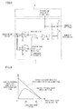
- FIG. 2 is a diagram illustrating an example in which a bipolar voltage is applied to a machining gap between the wire electrode 1 and the workpiece 2 for a period of one microsecond or less with a quiescent time longer than the duration of voltage application between each two adjacent cycles of voltage application.
- (1) represents an on-command for a high-speed switching element 42 shown in FIG. 1
- (2) represents the waveform of a machining power supply output delivered from the machining power source 4
- (3) represents the waveform of a machining-gap voltage produced by the machining power supply output and applied to the machining gap.
- positive and negative voltage components are shown to be alternately applied in FIG. 2
- two or more positive or negative voltage components may be consecutively applied.
- a stray capacitance exists in the machining gap and the feeder 5. If electric discharge does not occur, reductions in voltage are negligible. Consequently, the voltage waveform during the quiescent time is flat, as indicated by (3) of FIG. 2 , and the waveform of the machining-gap voltage is trapezoidal.
- a machining-gap impedance consists mainly of the contact impedances between a feeder (not shown) of the feeding portion 6 and the wire electrode 1, the impedance of the wire electrode 1 itself, the contact impedances between the wire electrode 1 and the workpiece 2, and the contact impedances between the workpiece 2 and the table.
- a voltage is produced in the machining gap even in case of a short-circuit, so that the short-circuit cannot be easily distinguished from electric discharge.
- (1) represents examples of such machining-gap voltage waveforms.
- a short-circuit is identified if a predetermined electric discharge decision level has never been exceeded, and electric discharge is identified once the predetermined decision level is exceeded.
- An open-circuit can be definitely identified in the manner described later.
- Variations in the response and component characteristics of a detection circuit are very influential at a high frequency, as in the case of an average machining-gap voltage. As indicated by a dotted line in (1) of FIG. 3 , therefore, the electric discharge decision level needs to be increased to a level free from the influence of variation in waveforms at the time of a short-circuit. In the cases of electric discharge waveforms (b) and (c) in (1) of FIG. 3 , however, the decision, whether a short-circuit or electric discharge, also depends on the machine due to the influence of the variation in the response and component characteristics of the detection circuit. Thus, the result of machining varies depending on the machine, though not to such a degree as in the case of the average voltage.
- machining-gap voltage waveform (e) in (2) of FIG. 3 is detected from the machining-gap voltage by using a method (see (1) of FIG. 2 ) in which a high-frequency voltage is applied with a quiescent time provided between each two adjacent cycles of voltage application. Based on the result of this detection, axis feed control is performed for the wire electric discharge machine.
- the electric discharge machine of the present invention can avoid the influence of the variation in the detection circuit, so that the result of machining becomes uniform.
- each duty cycle is assumed to be a period from the start of voltage application of a positive or negative voltage to the start of voltage application of another positive or negative voltage, including a quiescent time interposed therebetween.
- V1 represents an open-circuit decision level.
- T1 represents a time duration from the start of voltage application until an open-circuit is identified within each duty cycle.
- the open-circuit decision level V1 should optimally be about 50 to 60% of the supply voltage.
- the absolute value of the machining-gap voltage exceeds the decision level V1 when the time duration T1 has elapsed since the start of voltage application.
- the absolute value of the machining-gap voltage is lower than the decision level V1 when the time duration T1 has elapsed since the start of voltage application.
- each duty cycle is shown to terminate when the time duration T1 has elapsed since the start of voltage application.
- the point in time when the time duration T1 has elapsed since the start of voltage application may be assumed to be any point during the quiescent time before the end of each duty cycle.
- FIG. 5 shows an example of the decision circuit for identifying the open-circuit state of the machining gap.
- the machining state detection unit 7 is provided with the decision circuit.
- the machining-gap voltage is input to a differential amplifier circuit that comprises first and second operational amplifiers 71 and 72, and is amplified or attenuated to a predetermined level.
- a voltage of a polarity opposite to that of a voltage input to the first operational amplifier 71 is input to the second operational amplifier 72.
- the open-circuit decision level V1 and the machining-gap voltage which is amplified or attenuated by the differential amplifier circuit that comprises the first and second operational amplifiers 71 and 72, are input to comparators 73 and 74. Then, the levels of output signals from the operational amplifiers 71 and 72 are read when the time duration T1 has elapsed since the start of voltage application.
- the open-circuit state is identified if the output level of at least one of the comparators 73 and 74 is high, while the electric-discharge or short-circuit state is identified if both outputs are high.
- the open-circuit decision level V1 shown in (2) and (3) of FIG. 4 is given by a reference voltage VR in FIG. 5 .
- the respective outputs of the first and second comparators 73 and 74 are input to an OR gate 75, and their logical sum is output from the OR gate 75 to an AND gate 76.
- the AND gate 76 also receives pulses that are generated at a predetermined point in time within a quiescent time after the voltage application during each duty cycle.
- the AND gate 76 outputs a high signal if the open-circuit state is identified by the first or second comparator 73 or 74.
- a second counter 78 counts the number of high signals (or the number of open-circuits) output from the AND gate 76.
- a first counter 77 obtains the number of duty cycles by counting the number of pulses generated during each duty cycle.
- the number of open-circuits is counted for each unit time by the second counter 78, and the result of this counting is transferred to the numerical controller 9 ( FIG. 1 ). Thereupon, the numerical controller 9 can obtain the number of open-circuits per unit time. At the same time, the number of duty cycles is counted for each unit time by the first counter 77, and the result of this counting is transferred to the numerical controller 9. Thereupon, the numerical controller 9 can obtain the number of duty cycles.
- the ratio of the number of open-circuits to the number of duty cycles that is, an open-circuit ratio, can be calculated by the first and second counters 77 and 78.
- the average machining-gap voltage can be approximately obtained according to the following approximate equations (1) and (2).
- electric-discharge ratio + short-circuit ratio 1 - open-circuit ratio
- the electric-discharge ratio and short-circuit ratio within unit time can be obtained based on the "electric-discharge ratio within unit time” and measured "open-circuit ratio within unit time” shown in the graph of FIG. 6 .
- machining-gap voltage waveforms (a) to (e) shown in (1) of FIG. 3 there are electric discharge cycles of various energies, and a machining amount obtained by each electric discharge cycle is not constant. Based on this circumstance, the amounts given by the following approximate equations (6) and (7) may possibly be used as indices representative of machining states. These indices approximately represent machining amounts per unit time. Machining amount per unit time ⁇ ⁇ ⁇ frequency of electric discharge per unit time + ⁇ ⁇ number of short - circuits per unit time , Machining amount per unit distance ⁇ machining amount per unit time ⁇ movement distance per unit time .
- ⁇ and ⁇ are experimentally obtained constants that represent the degrees to which a single electric discharge cycle and a single short-circuit contribute to machining, respectively.
- the value of ⁇ is zero.
Landscapes
- Engineering & Computer Science (AREA)
- Mechanical Engineering (AREA)
- Chemical & Material Sciences (AREA)
- Chemical Kinetics & Catalysis (AREA)
- Electrochemistry (AREA)
- Electrical Discharge Machining, Electrochemical Machining, And Combined Machining (AREA)
Priority Applications (1)
| Application Number | Priority Date | Filing Date | Title |
|---|---|---|---|
| EP12172865.3A EP2505293B1 (de) | 2010-08-26 | 2011-06-01 | Elektrische Drahterodiermaschine mit Funktion zur Erfassung des Bearbeitungszustands |
Applications Claiming Priority (1)
| Application Number | Priority Date | Filing Date | Title |
|---|---|---|---|
| JP2010189521A JP5073797B2 (ja) | 2010-08-26 | 2010-08-26 | 加工状態を検出するワイヤ放電加工機 |
Related Child Applications (2)
| Application Number | Title | Priority Date | Filing Date |
|---|---|---|---|
| EP12172865.3A Division-Into EP2505293B1 (de) | 2010-08-26 | 2011-06-01 | Elektrische Drahterodiermaschine mit Funktion zur Erfassung des Bearbeitungszustands |
| EP12172865.3A Division EP2505293B1 (de) | 2010-08-26 | 2011-06-01 | Elektrische Drahterodiermaschine mit Funktion zur Erfassung des Bearbeitungszustands |
Publications (3)
| Publication Number | Publication Date |
|---|---|
| EP2422911A2 true EP2422911A2 (de) | 2012-02-29 |
| EP2422911A3 EP2422911A3 (de) | 2012-04-18 |
| EP2422911B1 EP2422911B1 (de) | 2015-11-25 |
Family
ID=44118119
Family Applications (2)
| Application Number | Title | Priority Date | Filing Date |
|---|---|---|---|
| EP12172865.3A Active EP2505293B1 (de) | 2010-08-26 | 2011-06-01 | Elektrische Drahterodiermaschine mit Funktion zur Erfassung des Bearbeitungszustands |
| EP11168391.8A Active EP2422911B1 (de) | 2010-08-26 | 2011-06-01 | Elektrische Drahterodiermaschine mit Funktion zur Erfassung des Bearbeitungszustands |
Family Applications Before (1)
| Application Number | Title | Priority Date | Filing Date |
|---|---|---|---|
| EP12172865.3A Active EP2505293B1 (de) | 2010-08-26 | 2011-06-01 | Elektrische Drahterodiermaschine mit Funktion zur Erfassung des Bearbeitungszustands |
Country Status (4)
| Country | Link |
|---|---|
| US (1) | US8975554B2 (de) |
| EP (2) | EP2505293B1 (de) |
| JP (1) | JP5073797B2 (de) |
| CN (2) | CN103949733B (de) |
Cited By (2)
| Publication number | Priority date | Publication date | Assignee | Title |
|---|---|---|---|---|
| EP2623245A3 (de) * | 2012-02-01 | 2014-10-22 | Fanuc Corporation | Drahterodiermaschine, die zum Erkennen des Bearbeitungszustandes und zur Bestimmung der mittleren Spannung in einem Bearbeitungsspalt in der Lage ist |
| EP2829348A3 (de) * | 2013-07-24 | 2015-02-11 | Fanuc Corporation | Drahterodiermaschine mit Einheit zur Berechnung der durchschnittlichen Entladungsverzögerungszeit |
Families Citing this family (14)
| Publication number | Priority date | Publication date | Assignee | Title |
|---|---|---|---|---|
| JP5968019B2 (ja) * | 2012-04-10 | 2016-08-10 | 三菱電機株式会社 | ワイヤ放電加工装置 |
| CN104245200B (zh) * | 2012-04-16 | 2018-01-12 | 株式会社牧野铣床制作所 | 机床 |
| CN102909447B (zh) * | 2012-09-19 | 2014-06-18 | 南京航空航天大学 | 基于电流脉冲概率检测的电火花伺服控制方法 |
| JP5722290B2 (ja) | 2012-09-20 | 2015-05-20 | ファナック株式会社 | 軸送り制御方式判別機能を有するワイヤ放電加工機 |
| JP5642810B2 (ja) * | 2013-01-08 | 2014-12-17 | ファナック株式会社 | 放電加工用電源装置 |
| JP6219785B2 (ja) * | 2014-06-23 | 2017-10-25 | ファナック株式会社 | 断線修復手段を備えたワイヤ放電加工機 |
| JP6325392B2 (ja) * | 2014-08-12 | 2018-05-16 | ファナック株式会社 | 短絡状態から加工開始可能なワイヤ放電加工機 |
| CN104400164A (zh) * | 2014-10-30 | 2015-03-11 | 苏州市宝玛数控设备有限公司 | 用于电火花线切割机床中可自动控制恒切深的控制装置 |
| JP6227599B2 (ja) | 2015-08-25 | 2017-11-08 | ファナック株式会社 | 極間距離を一定にするワイヤ放電加工機 |
| JP6360212B1 (ja) * | 2017-01-31 | 2018-07-18 | ファナック株式会社 | ワイヤ放電加工機 |
| JP6770041B2 (ja) * | 2018-10-23 | 2020-10-14 | ファナック株式会社 | ワイヤ放電加工機および放電加工方法 |
| JP2020165825A (ja) * | 2019-03-29 | 2020-10-08 | アズビル株式会社 | 火炎検出システムおよび故障診断方法 |
| JP2020165830A (ja) * | 2019-03-29 | 2020-10-08 | アズビル株式会社 | 火炎検出システムおよび火炎レベル検出方法 |
| CN110988633B (zh) * | 2019-12-20 | 2021-10-26 | 中南大学 | 一种电火花线切割加工过程自适应调整的多功能监测方法 |
Citations (3)
| Publication number | Priority date | Publication date | Assignee | Title |
|---|---|---|---|---|
| JPS61260915A (ja) | 1985-05-15 | 1986-11-19 | Mitsubishi Electric Corp | 放電加工用電源 |
| JP2002254250A (ja) | 2000-12-25 | 2002-09-10 | Fanuc Ltd | ワイヤ放電加工機の制御装置 |
| JP2004022275A (ja) | 2002-06-14 | 2004-01-22 | Sony Corp | 電池格納構造 |
Family Cites Families (31)
| Publication number | Priority date | Publication date | Assignee | Title |
|---|---|---|---|---|
| CH536679A (de) * | 1970-01-22 | 1973-05-15 | Kondo Iwao | Elektroerosionsgerät |
| US3705286A (en) * | 1971-01-21 | 1972-12-05 | Iwao Kondo | Electric discharge machining device |
| JPS59330B2 (ja) | 1974-07-30 | 1984-01-06 | 三菱電機株式会社 | ホウデンカコウセイギヨホウホウ オヨビ ソノソウチ |
| JPS5344993A (en) | 1976-10-04 | 1978-04-22 | Inoue Japax Res Inc | Servo equipment for electric machining |
| JPS54159795A (en) * | 1978-06-07 | 1979-12-17 | Hitachi Seiko Ltd | Indicator of spark machining condition |
| US4303957A (en) * | 1979-06-27 | 1981-12-01 | Colt Industries Operating Corp | Gap condition sensing circuit for electrical discharge machining power supply |
| US4481095A (en) * | 1982-02-03 | 1984-11-06 | Inoue-Japax Research Incorporated | Apparatus for supplying a working fluid and a wire electrode to a work portion of a wire-cut electrical discharge machine |
| US4504722A (en) * | 1982-02-26 | 1985-03-12 | Hitachi Seiko Ltd. | Fully automated machining apparatus optimization for electric discharge machining apparatus |
| CH678825A5 (de) * | 1986-06-03 | 1991-11-15 | Mitsubishi Electric Corp | |
| JPS63185521A (ja) * | 1987-01-28 | 1988-08-01 | Mitsubishi Electric Corp | 放電加工装置 |
| JP2588199B2 (ja) | 1987-06-30 | 1997-03-05 | 株式会社東芝 | 放電加工装置 |
| JPH0197522A (ja) * | 1987-10-09 | 1989-04-17 | Fanuc Ltd | 放電加工機における放電パターン検出装置 |
| EP0372036A1 (de) * | 1988-05-16 | 1990-06-13 | Charmilles Technologies S.A. | Vorrichtung und verfahren zur permanentadaptiv-regelung für edm-drahtschneidemaschinen |
| US5496984A (en) * | 1992-01-07 | 1996-03-05 | Mitsubishi Denki Kabushiki Kaisha | Electrical discharge machine and machining method therefor |
| JP3006818B2 (ja) * | 1994-03-09 | 2000-02-07 | 日本電気株式会社 | 放電加工方法および装置 |
| JP3293416B2 (ja) * | 1994-08-09 | 2002-06-17 | 三菱電機株式会社 | 放電加工機の放電状態検出装置 |
| JP3341494B2 (ja) * | 1994-10-25 | 2002-11-05 | 三菱電機株式会社 | ワイヤ放電加工機の電源制御装置 |
| JP3382756B2 (ja) * | 1995-07-31 | 2003-03-04 | 三菱電機株式会社 | 放電加工装置および放電加工方法 |
| JP3409960B2 (ja) * | 1996-03-12 | 2003-05-26 | 日立ビアメカニクス株式会社 | ワイヤ放電加工機の加工電圧検出装置 |
| CH695886A5 (de) * | 2000-10-20 | 2006-10-13 | Mitsubishi Electric Corp | Energieversorgungsapparat für die Drahtfunkenerosion. |
| EP1803519A3 (de) * | 2000-12-25 | 2007-10-10 | Fanuc Ltd | Steuerung für Drahtfunkenerosionsbearbeitung |
| WO2002058874A1 (fr) * | 2001-01-23 | 2002-08-01 | Mitsubishi Denki Kabushiki Kaisha | Usinage par decharge electrique a fil et alimentation electrique pour l'usinage par decharge electrique a fil |
| US6756887B2 (en) * | 2001-07-23 | 2004-06-29 | Wayne W. Evans | Method and apparatus for the dynamic vector control of automatic variable range and directional reception of gps global positioning signals, dynamic vehicle tracking, remote notification of collision and synthetic voice data communications |
| KR100496399B1 (ko) | 2002-06-12 | 2005-06-17 | 미쓰비시덴키 가부시키가이샤 | 와이어 방전가공기의 가공전원장치 |
| US7038158B2 (en) | 2002-08-30 | 2006-05-02 | Mitsubishi Denki Kabushiki Kaisha | Wire electrical discharge machining apparatus |
| JP2004136410A (ja) * | 2002-10-18 | 2004-05-13 | Fanuc Ltd | 放電加工装置 |
| WO2005072900A1 (ja) * | 2004-01-29 | 2005-08-11 | Mitsubishi Denki Kabushiki Kaisha | 放電加工装置及び放電加工方法 |
| US7638726B2 (en) * | 2005-09-15 | 2009-12-29 | Mitsubishi Electric Corporation | Wire electric discharge machining apparatus and wire electric discharge machining method |
| WO2008047452A1 (en) * | 2006-10-20 | 2008-04-24 | Mitsubishi Electric Corporation | Power supply control unit of electric discharge machine |
| JP5236368B2 (ja) | 2008-07-03 | 2013-07-17 | ファナック株式会社 | 単一電源を備えたワイヤ放電加工機 |
| JP5204321B1 (ja) * | 2012-02-01 | 2013-06-05 | ファナック株式会社 | 加工状態を検出し極間の平均電圧を求めるワイヤ放電加工機 |
-
2010
- 2010-08-26 JP JP2010189521A patent/JP5073797B2/ja active Active
-
2011
- 2011-06-01 EP EP12172865.3A patent/EP2505293B1/de active Active
- 2011-06-01 EP EP11168391.8A patent/EP2422911B1/de active Active
- 2011-06-02 US US13/151,769 patent/US8975554B2/en active Active
- 2011-08-24 CN CN201410200320.1A patent/CN103949733B/zh active Active
- 2011-08-24 CN CN201110253651.8A patent/CN102380677B/zh active Active
Patent Citations (3)
| Publication number | Priority date | Publication date | Assignee | Title |
|---|---|---|---|---|
| JPS61260915A (ja) | 1985-05-15 | 1986-11-19 | Mitsubishi Electric Corp | 放電加工用電源 |
| JP2002254250A (ja) | 2000-12-25 | 2002-09-10 | Fanuc Ltd | ワイヤ放電加工機の制御装置 |
| JP2004022275A (ja) | 2002-06-14 | 2004-01-22 | Sony Corp | 電池格納構造 |
Cited By (5)
| Publication number | Priority date | Publication date | Assignee | Title |
|---|---|---|---|---|
| EP2623245A3 (de) * | 2012-02-01 | 2014-10-22 | Fanuc Corporation | Drahterodiermaschine, die zum Erkennen des Bearbeitungszustandes und zur Bestimmung der mittleren Spannung in einem Bearbeitungsspalt in der Lage ist |
| EP2829348A3 (de) * | 2013-07-24 | 2015-02-11 | Fanuc Corporation | Drahterodiermaschine mit Einheit zur Berechnung der durchschnittlichen Entladungsverzögerungszeit |
| US9833853B2 (en) | 2013-07-24 | 2017-12-05 | Fanuc Corporation | Wire electric discharge machine including average discharge delay time calculating unit |
| US10543546B2 (en) | 2013-07-24 | 2020-01-28 | Fanuc Corporation | Wire electric discharge machine including average discharge delay time calculating unit |
| US10792744B2 (en) | 2013-07-24 | 2020-10-06 | Fanuc Corporation | Wire electric discharge machine including average discharge delay time calculating unit |
Also Published As
| Publication number | Publication date |
|---|---|
| JP5073797B2 (ja) | 2012-11-14 |
| CN102380677A (zh) | 2012-03-21 |
| JP2012045662A (ja) | 2012-03-08 |
| EP2422911B1 (de) | 2015-11-25 |
| CN102380677B (zh) | 2014-10-01 |
| EP2422911A3 (de) | 2012-04-18 |
| US20120048833A1 (en) | 2012-03-01 |
| CN103949733A (zh) | 2014-07-30 |
| US8975554B2 (en) | 2015-03-10 |
| EP2505293A1 (de) | 2012-10-03 |
| CN103949733B (zh) | 2017-06-06 |
| EP2505293B1 (de) | 2015-11-25 |
Similar Documents
| Publication | Publication Date | Title |
|---|---|---|
| EP2422911B1 (de) | Elektrische Drahterodiermaschine mit Funktion zur Erfassung des Bearbeitungszustands | |
| EP2623245B1 (de) | Drahterodierverfahren, das zum Erkennen des Bearbeitungszustandes und zur Bestimmung der mittleren Spannung in einem Bearbeitungsspalt in der Lage ist und entsprechende Drahterodiermaschine | |
| EP2269755B1 (de) | Elektrische Drahterodiermaschine mit Funktion zur Unterscheidung des mechanischen Bearbeitungsstatus | |
| US10792744B2 (en) | Wire electric discharge machine including average discharge delay time calculating unit | |
| JP4833198B2 (ja) | 放電加工機の電源制御装置 | |
| EP3251778B1 (de) | Drahterosionsmaschine | |
| US8519295B2 (en) | Controller of electrical discharge machine | |
| JP5357298B2 (ja) | 加工状態を検出するワイヤ放電加工機 | |
| JPH0276624A (ja) | 放電加工装置 | |
| JPH0665444B2 (ja) | 放電加工装置 | |
| JPH0659570B2 (ja) | 放電加工装置 |
Legal Events
| Date | Code | Title | Description |
|---|---|---|---|
| AK | Designated contracting states |
Kind code of ref document: A2 Designated state(s): AL AT BE BG CH CY CZ DE DK EE ES FI FR GB GR HR HU IE IS IT LI LT LU LV MC MK MT NL NO PL PT RO RS SE SI SK SM TR |
|
| AX | Request for extension of the european patent |
Extension state: BA ME |
|
| PUAI | Public reference made under article 153(3) epc to a published international application that has entered the european phase |
Free format text: ORIGINAL CODE: 0009012 |
|
| PUAL | Search report despatched |
Free format text: ORIGINAL CODE: 0009013 |
|
| AK | Designated contracting states |
Kind code of ref document: A3 Designated state(s): AL AT BE BG CH CY CZ DE DK EE ES FI FR GB GR HR HU IE IS IT LI LT LU LV MC MK MT NL NO PL PT RO RS SE SI SK SM TR |
|
| AX | Request for extension of the european patent |
Extension state: BA ME |
|
| RIC1 | Information provided on ipc code assigned before grant |
Ipc: B23H 7/18 20060101AFI20120312BHEP |
|
| 17P | Request for examination filed |
Effective date: 20121015 |
|
| 17Q | First examination report despatched |
Effective date: 20140923 |
|
| GRAP | Despatch of communication of intention to grant a patent |
Free format text: ORIGINAL CODE: EPIDOSNIGR1 |
|
| INTG | Intention to grant announced |
Effective date: 20150626 |
|
| GRAS | Grant fee paid |
Free format text: ORIGINAL CODE: EPIDOSNIGR3 |
|
| GRAA | (expected) grant |
Free format text: ORIGINAL CODE: 0009210 |
|
| AK | Designated contracting states |
Kind code of ref document: B1 Designated state(s): AL AT BE BG CH CY CZ DE DK EE ES FI FR GB GR HR HU IE IS IT LI LT LU LV MC MK MT NL NO PL PT RO RS SE SI SK SM TR |
|
| REG | Reference to a national code |
Ref country code: GB Ref legal event code: FG4D |
|
| REG | Reference to a national code |
Ref country code: CH Ref legal event code: EP |
|
| REG | Reference to a national code |
Ref country code: AT Ref legal event code: REF Ref document number: 762341 Country of ref document: AT Kind code of ref document: T Effective date: 20151215 Ref country code: CH Ref legal event code: NV Representative=s name: DR. LUSUARDI AG, CH |
|
| REG | Reference to a national code |
Ref country code: IE Ref legal event code: FG4D |
|
| REG | Reference to a national code |
Ref country code: DE Ref legal event code: R096 Ref document number: 602011021573 Country of ref document: DE |
|
| REG | Reference to a national code |
Ref country code: LT Ref legal event code: MG4D |
|
| REG | Reference to a national code |
Ref country code: NL Ref legal event code: MP Effective date: 20160225 |
|
| REG | Reference to a national code |
Ref country code: AT Ref legal event code: MK05 Ref document number: 762341 Country of ref document: AT Kind code of ref document: T Effective date: 20151125 |
|
| PG25 | Lapsed in a contracting state [announced via postgrant information from national office to epo] |
Ref country code: HR Free format text: LAPSE BECAUSE OF FAILURE TO SUBMIT A TRANSLATION OF THE DESCRIPTION OR TO PAY THE FEE WITHIN THE PRESCRIBED TIME-LIMIT Effective date: 20151125 Ref country code: NO Free format text: LAPSE BECAUSE OF FAILURE TO SUBMIT A TRANSLATION OF THE DESCRIPTION OR TO PAY THE FEE WITHIN THE PRESCRIBED TIME-LIMIT Effective date: 20160225 Ref country code: LT Free format text: LAPSE BECAUSE OF FAILURE TO SUBMIT A TRANSLATION OF THE DESCRIPTION OR TO PAY THE FEE WITHIN THE PRESCRIBED TIME-LIMIT Effective date: 20151125 Ref country code: ES Free format text: LAPSE BECAUSE OF FAILURE TO SUBMIT A TRANSLATION OF THE DESCRIPTION OR TO PAY THE FEE WITHIN THE PRESCRIBED TIME-LIMIT Effective date: 20151125 Ref country code: IS Free format text: LAPSE BECAUSE OF FAILURE TO SUBMIT A TRANSLATION OF THE DESCRIPTION OR TO PAY THE FEE WITHIN THE PRESCRIBED TIME-LIMIT Effective date: 20160325 Ref country code: NL Free format text: LAPSE BECAUSE OF FAILURE TO SUBMIT A TRANSLATION OF THE DESCRIPTION OR TO PAY THE FEE WITHIN THE PRESCRIBED TIME-LIMIT Effective date: 20151125 |
|
| PG25 | Lapsed in a contracting state [announced via postgrant information from national office to epo] |
Ref country code: LV Free format text: LAPSE BECAUSE OF FAILURE TO SUBMIT A TRANSLATION OF THE DESCRIPTION OR TO PAY THE FEE WITHIN THE PRESCRIBED TIME-LIMIT Effective date: 20151125 Ref country code: GR Free format text: LAPSE BECAUSE OF FAILURE TO SUBMIT A TRANSLATION OF THE DESCRIPTION OR TO PAY THE FEE WITHIN THE PRESCRIBED TIME-LIMIT Effective date: 20160226 Ref country code: RS Free format text: LAPSE BECAUSE OF FAILURE TO SUBMIT A TRANSLATION OF THE DESCRIPTION OR TO PAY THE FEE WITHIN THE PRESCRIBED TIME-LIMIT Effective date: 20151125 Ref country code: PT Free format text: LAPSE BECAUSE OF FAILURE TO SUBMIT A TRANSLATION OF THE DESCRIPTION OR TO PAY THE FEE WITHIN THE PRESCRIBED TIME-LIMIT Effective date: 20160325 Ref country code: PL Free format text: LAPSE BECAUSE OF FAILURE TO SUBMIT A TRANSLATION OF THE DESCRIPTION OR TO PAY THE FEE WITHIN THE PRESCRIBED TIME-LIMIT Effective date: 20151125 Ref country code: SE Free format text: LAPSE BECAUSE OF FAILURE TO SUBMIT A TRANSLATION OF THE DESCRIPTION OR TO PAY THE FEE WITHIN THE PRESCRIBED TIME-LIMIT Effective date: 20151125 Ref country code: AT Free format text: LAPSE BECAUSE OF FAILURE TO SUBMIT A TRANSLATION OF THE DESCRIPTION OR TO PAY THE FEE WITHIN THE PRESCRIBED TIME-LIMIT Effective date: 20151125 Ref country code: FI Free format text: LAPSE BECAUSE OF FAILURE TO SUBMIT A TRANSLATION OF THE DESCRIPTION OR TO PAY THE FEE WITHIN THE PRESCRIBED TIME-LIMIT Effective date: 20151125 |
|
| PG25 | Lapsed in a contracting state [announced via postgrant information from national office to epo] |
Ref country code: CZ Free format text: LAPSE BECAUSE OF FAILURE TO SUBMIT A TRANSLATION OF THE DESCRIPTION OR TO PAY THE FEE WITHIN THE PRESCRIBED TIME-LIMIT Effective date: 20151125 Ref country code: IT Free format text: LAPSE BECAUSE OF FAILURE TO SUBMIT A TRANSLATION OF THE DESCRIPTION OR TO PAY THE FEE WITHIN THE PRESCRIBED TIME-LIMIT Effective date: 20151125 |
|
| REG | Reference to a national code |
Ref country code: DE Ref legal event code: R097 Ref document number: 602011021573 Country of ref document: DE |
|
| PG25 | Lapsed in a contracting state [announced via postgrant information from national office to epo] |
Ref country code: EE Free format text: LAPSE BECAUSE OF FAILURE TO SUBMIT A TRANSLATION OF THE DESCRIPTION OR TO PAY THE FEE WITHIN THE PRESCRIBED TIME-LIMIT Effective date: 20151125 Ref country code: RO Free format text: LAPSE BECAUSE OF FAILURE TO SUBMIT A TRANSLATION OF THE DESCRIPTION OR TO PAY THE FEE WITHIN THE PRESCRIBED TIME-LIMIT Effective date: 20151125 Ref country code: SK Free format text: LAPSE BECAUSE OF FAILURE TO SUBMIT A TRANSLATION OF THE DESCRIPTION OR TO PAY THE FEE WITHIN THE PRESCRIBED TIME-LIMIT Effective date: 20151125 Ref country code: DK Free format text: LAPSE BECAUSE OF FAILURE TO SUBMIT A TRANSLATION OF THE DESCRIPTION OR TO PAY THE FEE WITHIN THE PRESCRIBED TIME-LIMIT Effective date: 20151125 Ref country code: SM Free format text: LAPSE BECAUSE OF FAILURE TO SUBMIT A TRANSLATION OF THE DESCRIPTION OR TO PAY THE FEE WITHIN THE PRESCRIBED TIME-LIMIT Effective date: 20151125 |
|
| PLBE | No opposition filed within time limit |
Free format text: ORIGINAL CODE: 0009261 |
|
| STAA | Information on the status of an ep patent application or granted ep patent |
Free format text: STATUS: NO OPPOSITION FILED WITHIN TIME LIMIT |
|
| 26N | No opposition filed |
Effective date: 20160826 |
|
| PG25 | Lapsed in a contracting state [announced via postgrant information from national office to epo] |
Ref country code: SI Free format text: LAPSE BECAUSE OF FAILURE TO SUBMIT A TRANSLATION OF THE DESCRIPTION OR TO PAY THE FEE WITHIN THE PRESCRIBED TIME-LIMIT Effective date: 20151125 |
|
| PG25 | Lapsed in a contracting state [announced via postgrant information from national office to epo] |
Ref country code: BE Free format text: LAPSE BECAUSE OF FAILURE TO SUBMIT A TRANSLATION OF THE DESCRIPTION OR TO PAY THE FEE WITHIN THE PRESCRIBED TIME-LIMIT Effective date: 20151125 |
|
| PG25 | Lapsed in a contracting state [announced via postgrant information from national office to epo] |
Ref country code: MC Free format text: LAPSE BECAUSE OF FAILURE TO SUBMIT A TRANSLATION OF THE DESCRIPTION OR TO PAY THE FEE WITHIN THE PRESCRIBED TIME-LIMIT Effective date: 20151125 |
|
| GBPC | Gb: european patent ceased through non-payment of renewal fee |
Effective date: 20160601 |
|
| REG | Reference to a national code |
Ref country code: IE Ref legal event code: MM4A |
|
| REG | Reference to a national code |
Ref country code: FR Ref legal event code: ST Effective date: 20170228 |
|
| PG25 | Lapsed in a contracting state [announced via postgrant information from national office to epo] |
Ref country code: FR Free format text: LAPSE BECAUSE OF NON-PAYMENT OF DUE FEES Effective date: 20160630 |
|
| PG25 | Lapsed in a contracting state [announced via postgrant information from national office to epo] |
Ref country code: IE Free format text: LAPSE BECAUSE OF NON-PAYMENT OF DUE FEES Effective date: 20160601 Ref country code: GB Free format text: LAPSE BECAUSE OF NON-PAYMENT OF DUE FEES Effective date: 20160601 |
|
| PG25 | Lapsed in a contracting state [announced via postgrant information from national office to epo] |
Ref country code: CY Free format text: LAPSE BECAUSE OF FAILURE TO SUBMIT A TRANSLATION OF THE DESCRIPTION OR TO PAY THE FEE WITHIN THE PRESCRIBED TIME-LIMIT Effective date: 20151125 Ref country code: HU Free format text: LAPSE BECAUSE OF FAILURE TO SUBMIT A TRANSLATION OF THE DESCRIPTION OR TO PAY THE FEE WITHIN THE PRESCRIBED TIME-LIMIT; INVALID AB INITIO Effective date: 20110601 |
|
| PG25 | Lapsed in a contracting state [announced via postgrant information from national office to epo] |
Ref country code: LU Free format text: LAPSE BECAUSE OF NON-PAYMENT OF DUE FEES Effective date: 20160601 Ref country code: TR Free format text: LAPSE BECAUSE OF FAILURE TO SUBMIT A TRANSLATION OF THE DESCRIPTION OR TO PAY THE FEE WITHIN THE PRESCRIBED TIME-LIMIT Effective date: 20151125 Ref country code: MT Free format text: LAPSE BECAUSE OF NON-PAYMENT OF DUE FEES Effective date: 20160630 Ref country code: MK Free format text: LAPSE BECAUSE OF FAILURE TO SUBMIT A TRANSLATION OF THE DESCRIPTION OR TO PAY THE FEE WITHIN THE PRESCRIBED TIME-LIMIT Effective date: 20151125 |
|
| PG25 | Lapsed in a contracting state [announced via postgrant information from national office to epo] |
Ref country code: BG Free format text: LAPSE BECAUSE OF FAILURE TO SUBMIT A TRANSLATION OF THE DESCRIPTION OR TO PAY THE FEE WITHIN THE PRESCRIBED TIME-LIMIT Effective date: 20151125 |
|
| PG25 | Lapsed in a contracting state [announced via postgrant information from national office to epo] |
Ref country code: AL Free format text: LAPSE BECAUSE OF FAILURE TO SUBMIT A TRANSLATION OF THE DESCRIPTION OR TO PAY THE FEE WITHIN THE PRESCRIBED TIME-LIMIT Effective date: 20151125 |
|
| REG | Reference to a national code |
Ref country code: DE Ref legal event code: R082 Ref document number: 602011021573 Country of ref document: DE Representative=s name: HL KEMPNER PATENTANWAELTE, SOLICITORS (ENGLAND, DE Ref country code: DE Ref legal event code: R082 Ref document number: 602011021573 Country of ref document: DE Representative=s name: HL KEMPNER PARTG MBB, DE Ref country code: DE Ref legal event code: R082 Ref document number: 602011021573 Country of ref document: DE Representative=s name: HL KEMPNER PATENTANWALT, RECHTSANWALT, SOLICIT, DE |
|
| PGFP | Annual fee paid to national office [announced via postgrant information from national office to epo] |
Ref country code: DE Payment date: 20250520 Year of fee payment: 15 |
|
| PGFP | Annual fee paid to national office [announced via postgrant information from national office to epo] |
Ref country code: CH Payment date: 20250701 Year of fee payment: 15 |