EP2452838A1 - Lochabdichtungslaminat und Luftreifen mit einem derartigen Laminat - Google Patents
Lochabdichtungslaminat und Luftreifen mit einem derartigen Laminat Download PDFInfo
- Publication number
- EP2452838A1 EP2452838A1 EP11188348A EP11188348A EP2452838A1 EP 2452838 A1 EP2452838 A1 EP 2452838A1 EP 11188348 A EP11188348 A EP 11188348A EP 11188348 A EP11188348 A EP 11188348A EP 2452838 A1 EP2452838 A1 EP 2452838A1
- Authority
- EP
- European Patent Office
- Prior art keywords
- layer
- sealant material
- sealant
- laminate
- tire
- Prior art date
- Legal status (The legal status is an assumption and is not a legal conclusion. Google has not performed a legal analysis and makes no representation as to the accuracy of the status listed.)
- Withdrawn
Links
- 239000000565 sealant Substances 0.000 title claims abstract description 92
- 239000012812 sealant material Substances 0.000 claims abstract description 184
- 238000004519 manufacturing process Methods 0.000 claims abstract description 5
- 229920001971 elastomer Polymers 0.000 claims description 10
- 238000000034 method Methods 0.000 claims description 9
- 239000004744 fabric Substances 0.000 claims description 3
- 230000002265 prevention Effects 0.000 claims description 2
- 239000000463 material Substances 0.000 description 7
- 230000008901 benefit Effects 0.000 description 5
- 239000011324 bead Substances 0.000 description 2
- 230000005012 migration Effects 0.000 description 2
- 238000013508 migration Methods 0.000 description 2
- 230000001419 dependent effect Effects 0.000 description 1
- 239000000806 elastomer Substances 0.000 description 1
- 239000012530 fluid Substances 0.000 description 1
- 230000005484 gravity Effects 0.000 description 1
- 239000004033 plastic Substances 0.000 description 1
- 238000007789 sealing Methods 0.000 description 1
- 230000003068 static effect Effects 0.000 description 1
- 238000004073 vulcanization Methods 0.000 description 1
- 239000002759 woven fabric Substances 0.000 description 1
Images

Classifications
-
- B—PERFORMING OPERATIONS; TRANSPORTING
- B29—WORKING OF PLASTICS; WORKING OF SUBSTANCES IN A PLASTIC STATE IN GENERAL
- B29D—PRODUCING PARTICULAR ARTICLES FROM PLASTICS OR FROM SUBSTANCES IN A PLASTIC STATE
- B29D30/00—Producing pneumatic or solid tyres or parts thereof
- B29D30/06—Pneumatic tyres or parts thereof (e.g. produced by casting, moulding, compression moulding, injection moulding, centrifugal casting)
- B29D30/08—Building tyres
- B29D30/20—Building tyres by the flat-tyre method, i.e. building on cylindrical drums
- B29D30/30—Applying the layers; Guiding or stretching the layers during application
-
- B—PERFORMING OPERATIONS; TRANSPORTING
- B29—WORKING OF PLASTICS; WORKING OF SUBSTANCES IN A PLASTIC STATE IN GENERAL
- B29D—PRODUCING PARTICULAR ARTICLES FROM PLASTICS OR FROM SUBSTANCES IN A PLASTIC STATE
- B29D30/00—Producing pneumatic or solid tyres or parts thereof
- B29D30/06—Pneumatic tyres or parts thereof (e.g. produced by casting, moulding, compression moulding, injection moulding, centrifugal casting)
- B29D30/0681—Parts of pneumatic tyres; accessories, auxiliary operations
- B29D30/0685—Incorporating auto-repairing or self-sealing arrangements or agents on or into tyres
-
- B—PERFORMING OPERATIONS; TRANSPORTING
- B60—VEHICLES IN GENERAL
- B60C—VEHICLE TYRES; TYRE INFLATION; TYRE CHANGING; CONNECTING VALVES TO INFLATABLE ELASTIC BODIES IN GENERAL; DEVICES OR ARRANGEMENTS RELATED TO TYRES
- B60C19/00—Tyre parts or constructions not otherwise provided for
- B60C19/12—Puncture preventing arrangements
- B60C19/122—Puncture preventing arrangements disposed inside of the inner liner
-
- B—PERFORMING OPERATIONS; TRANSPORTING
- B29—WORKING OF PLASTICS; WORKING OF SUBSTANCES IN A PLASTIC STATE IN GENERAL
- B29C—SHAPING OR JOINING OF PLASTICS; SHAPING OF MATERIAL IN A PLASTIC STATE, NOT OTHERWISE PROVIDED FOR; AFTER-TREATMENT OF THE SHAPED PRODUCTS, e.g. REPAIRING
- B29C73/00—Repairing of articles made from plastics or substances in a plastic state, e.g. of articles shaped or produced by using techniques covered by this subclass or subclass B29D
- B29C73/16—Auto-repairing or self-sealing arrangements or agents
- B29C73/18—Auto-repairing or self-sealing arrangements or agents the article material itself being self-sealing, e.g. by compression
- B29C73/20—Auto-repairing or self-sealing arrangements or agents the article material itself being self-sealing, e.g. by compression the article material only consisting in part of a deformable sealing material
-
- B—PERFORMING OPERATIONS; TRANSPORTING
- B29—WORKING OF PLASTICS; WORKING OF SUBSTANCES IN A PLASTIC STATE IN GENERAL
- B29C—SHAPING OR JOINING OF PLASTICS; SHAPING OF MATERIAL IN A PLASTIC STATE, NOT OTHERWISE PROVIDED FOR; AFTER-TREATMENT OF THE SHAPED PRODUCTS, e.g. REPAIRING
- B29C73/00—Repairing of articles made from plastics or substances in a plastic state, e.g. of articles shaped or produced by using techniques covered by this subclass or subclass B29D
- B29C73/16—Auto-repairing or self-sealing arrangements or agents
- B29C73/22—Auto-repairing or self-sealing arrangements or agents the article containing elements including a sealing composition, e.g. powder being liberated when the article is damaged
-
- B—PERFORMING OPERATIONS; TRANSPORTING
- B29—WORKING OF PLASTICS; WORKING OF SUBSTANCES IN A PLASTIC STATE IN GENERAL
- B29D—PRODUCING PARTICULAR ARTICLES FROM PLASTICS OR FROM SUBSTANCES IN A PLASTIC STATE
- B29D30/00—Producing pneumatic or solid tyres or parts thereof
- B29D30/06—Pneumatic tyres or parts thereof (e.g. produced by casting, moulding, compression moulding, injection moulding, centrifugal casting)
- B29D30/0681—Parts of pneumatic tyres; accessories, auxiliary operations
- B29D2030/0682—Inner liners
-
- Y—GENERAL TAGGING OF NEW TECHNOLOGICAL DEVELOPMENTS; GENERAL TAGGING OF CROSS-SECTIONAL TECHNOLOGIES SPANNING OVER SEVERAL SECTIONS OF THE IPC; TECHNICAL SUBJECTS COVERED BY FORMER USPC CROSS-REFERENCE ART COLLECTIONS [XRACs] AND DIGESTS
- Y10—TECHNICAL SUBJECTS COVERED BY FORMER USPC
- Y10T—TECHNICAL SUBJECTS COVERED BY FORMER US CLASSIFICATION
- Y10T152/00—Resilient tires and wheels
- Y10T152/10—Tires, resilient
- Y10T152/10495—Pneumatic tire or inner tube
- Y10T152/10666—Automatic sealing of punctures [e.g., self-healing, etc.]
-
- Y—GENERAL TAGGING OF NEW TECHNOLOGICAL DEVELOPMENTS; GENERAL TAGGING OF CROSS-SECTIONAL TECHNOLOGIES SPANNING OVER SEVERAL SECTIONS OF THE IPC; TECHNICAL SUBJECTS COVERED BY FORMER USPC CROSS-REFERENCE ART COLLECTIONS [XRACs] AND DIGESTS
- Y10—TECHNICAL SUBJECTS COVERED BY FORMER USPC
- Y10T—TECHNICAL SUBJECTS COVERED BY FORMER US CLASSIFICATION
- Y10T152/00—Resilient tires and wheels
- Y10T152/10—Tires, resilient
- Y10T152/10495—Pneumatic tire or inner tube
- Y10T152/10666—Automatic sealing of punctures [e.g., self-healing, etc.]
- Y10T152/10675—Using flowable coating or composition
-
- Y—GENERAL TAGGING OF NEW TECHNOLOGICAL DEVELOPMENTS; GENERAL TAGGING OF CROSS-SECTIONAL TECHNOLOGIES SPANNING OVER SEVERAL SECTIONS OF THE IPC; TECHNICAL SUBJECTS COVERED BY FORMER USPC CROSS-REFERENCE ART COLLECTIONS [XRACs] AND DIGESTS
- Y10—TECHNICAL SUBJECTS COVERED BY FORMER USPC
- Y10T—TECHNICAL SUBJECTS COVERED BY FORMER US CLASSIFICATION
- Y10T152/00—Resilient tires and wheels
- Y10T152/10—Tires, resilient
- Y10T152/10495—Pneumatic tire or inner tube
- Y10T152/10666—Automatic sealing of punctures [e.g., self-healing, etc.]
- Y10T152/10675—Using flowable coating or composition
- Y10T152/10684—On inner surface of tubeless tire
- Y10T152/10693—Sealant in plural layers or plural pockets
Definitions
- This invention relates to a sealant laminate for use in a pneumatic tire and to a method of manufacturing such a tire.
- puncture sealants typically made of puncture sealing rubber or plastic material
- the puncture sealant forms a seal around the corresponding opening in the tire to minimize the loss of air pressure.
- puncture sealants are not recommended for higher speed tires because of the cold flow properties of the sealant material.
- the sealant material tends to migrate within the tire due to gravity during storage of the tire or when the vehicle that has the tire mounted to it is parked. This migration occurs because when the pneumatic tire with puncture sealant material is cured or vulcanized, the sealant material is depolymerized and thus can flow circumferentially or from side to side within the pocket created in the tire for the sealant material.
- the invention relates to a sealant laminate in accordance with claim 1, a pneumatic tire comprising such a laminate in accordance with claim 11 and a method of manufacturing a tire in accordance with claim 13.
- a pneumatic tire may comprise: an outer surface; an inner surface positioned radially inward of the outer surface; and, a puncture sealant laminate positioned radially between the inner surface and the outer surface.
- the puncture sealant laminate may have first and second ends and may comprise: a first layer of sealant material that extends from the first end to the second end of the puncture sealant laminate; a first layer of non-sealant material that is positioned radially outward of the first layer of sealant material and that extends from the first end to the second end of the puncture sealant laminate; a second layer of sealant material that is positioned radially outward of the first layer of non-sealant material and that extends from the first end to the second end of the puncture sealant laminate; a second layer of non-sealant material that is positioned radially outward of the second layer of sealant material and that extends from the first end to the second end of the puncture sealant laminate; and, a third layer of
- the first and second layers of non-sealant material may prevent the first, second, and third layers of sealant material from contacting each other.
- Each of the first and second layers of non-sealant material may have first and second ends that attach to rubber in the pneumatic tire that is not part of the puncture sealant laminate.
- a puncture sealant laminate for prevention of a flat tire in case of a puncture of a pneumatic tire may comprise: first and second ends; a first layer of sealant material that extends from the first end to the second end of the puncture sealant laminate; a first layer of non-sealant material that is positioned radially outward of the first layer of sealant material and that extends from the first end to the second end of the puncture sealant laminate; a second layer of sealant material that is positioned radially outward of the first layer of non-sealant material and that extends from the first end to the second end of the puncture sealant laminate; a second layer of non-sealant material that is positioned radially outward of the second layer of sealant material and that extends from the first end to the second end of the puncture sealant laminate; and, a third layer of sealant material that is positioned radially outward of the second layer of non-sealant material and that extends from the first
- the first and second layers of non-sealant material may prevent the first, second, and third layers of sealant material from contacting each other.
- the first and second layers of non-sealant material may have first and second ends that attach to rubber in the pneumatic tire that is not part of the puncture sealant laminate.
- a method of making a pneumatic tire may comprise the steps of: (a) applying an inner liner onto a tire building drum; (b) applying a puncture sealant laminate onto the tire building drum, the puncture sealant laminate comprising: (1) first and second ends; (2) a first layer of sealant material that extends from the first end to the second end of the puncture sealant laminate; (3) a first layer of non-sealant material that is positioned radially outward of the first layer of sealant material and that extends from the first end to the second end of the puncture sealant laminate; (4) a second layer of sealant material that is positioned radially outward of the first layer of non-sealant material and that extends from the first end to the second end of the puncture sealant laminate; (5) a second layer of non-sealant material that is positioned radially outward of the second layer of sealant material and that extends from the first end to the second end of the puncture sealant laminate; and,
- step (b) comprises the steps of applying the first layer of sealant material onto the inner liner, applying the first layer of non-sealant material onto the first layer of sealant material, applying the second layer of sealant material onto the first layer of non-sealant material, applying the second layer of non-sealant material onto the second layer of sealant material, and applying the third layer of sealant material onto the second layer of non-sealant material.
- step (b) comprises the steps of providing the first layer of sealant material with first and second axial edges, extending the first end of the first layer of non-sealant material over the first axial edge of the first layer of sealant material to form a boundary for the first axial edge of the first layer of sealant material, and extending the second end of the first layer of non-sealant material over the second axial edge of the first layer of sealant material to form a boundary for the second axial edge of the first layer of sealant material.
- step (b) comprises the steps of providing the second layer of sealant material with first and second axial edges, extending the first end of the second layer of non-sealant material over the first axial edge of the second layer of sealant material to form a boundary for the first axial edge of the second layer of sealant material, and extending the second end of the second layer of non-sealant material over the second axial edge of the second layer of sealant material to form a boundary for the second axial edge of the second layer of sealant material.
- the step of applying the second layer of non-sealant material onto the second layer of sealant material comprises the steps of contacting the first end of the second layer of non-sealant material to the first end of the first layer of non-sealant material, and contacting the second end of the second layer of non-sealant material to the second end of the first layer of non-sealant material.
- One advantage of this invention is that migration of sealant material within a pneumatic tire may be reduced.
- Another advantage of this invention is that higher speed pneumatic tires can include puncture sealant materials.
- Yet another advantage of this invention is that tire uniformity, especially for dynamic and static balance, can be improved.
- Axial and “axially” mean lines or directions that are parallel to the axis of rotation of the tire.
- “Circumferential” means lines or directions extending along the perimeter of the surface of the annular tread perpendicular to the axial direction.
- Equatorial plane means the plane perpendicular to the tire's axis of rotation and passing through the center of its tread.
- Inner Liner means the layer or layers of elastomer or other material that form the inside surface of a tubeless tire and that contain the inflating fluid within the tire.
- Ring and radially mean directions radially toward (inward) or away from (outward) the axis of rotation of the tire.
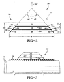
- FIGURE 1 shows a cross-sectional view of a pneumatic tire 10 having a puncture sealant laminate 30 according to one embodiment of this invention.
- the pneumatic tire 10 may be of any type and size chosen with the sound judgment of a person of skill in the art including a truck tire, a light truck tire or a passenger tire.
- the tire 10 may have a carcass 12 that may include a pair of annular beads 14 and one or more plies 16 that may extend from around the beads 14 as shown.
- the carcass 12 may define a crown region 18 and a pair of sidewalls 20.
- Other conventional components may be positioned on the carcass 12 such as an inner liner 22, sidewall rubber portions 24, a belt package 26 and a tread 28. Because a tire carcass and these other components are well known to those of skill in the art, further details will not be provided except as noted below.
- the puncture sealant laminate 30, which may have first and second ends 32, 34, is shown positioned in the crown region 18 radially outward of the inner liner 22 and radially inward of the plies 16.
- the puncture sealant laminate 30 can be positioned anywhere within the tire 10, chosen with the sound judgment of a person of skill in the art, between an outer surface 11 and an inner surface 13 of the tire 10.
- the puncture sealant laminate 30 may include: a first layer 36 of sealant material; a first layer 38 of non-sealant material that is positioned radially outward of the first layer 36of sealant material; a second layer 40 of sealant material that is positioned radially outward of the first layer 38 of non-sealant material; a second layer 42 of non-sealant material that is positioned radially outward of the second layer 40 of sealant material; and, a third layer 44 of sealant material that is positioned radially outward of the second layer 42 of non-sealant material.
- Each of the layers 36, 38, 40, 42, 44 may extend from the first end 32 to the second end 34 of the puncture sealant laminate 30, as shown.
- the first and second layers of non-sealant material 38, 42 prevent the first, second, and third layers of sealant material 36, 40, 44 from contacting each other.
- the first and second layers of non-sealant material 38, 42 serve as boundaries for the first, second, and third layers of sealant material 36, 40, 44.
- the sealant material(s), when depolymerized, remain in their proper circumferential position(s).
- each of the first and second layers 38, 42 of non-sealant material have first ends 46, 50, respectively and second ends 48, 52, respectively that attach to rubber in the pneumatic tire that is not part of the puncture sealant laminate 30. With this design the puncture sealant laminate 30 is held in place within the tire 10.
- each of the first and second layers 36, 40 of sealant material may have first axial edges 54, 58, respectively and second axial edges 56, 60, respectively.
- first end 46 of the first layer of non-sealant material 38 forms a boundary 62 for the first axial edge 54 of the first layer of sealant material 36 and the second end 48 of the first layer of non-sealant material 38 forms a boundary 64 for the second axial edge 58 of the first layer of sealant material 36.
- first end 50 of the second layer of non-sealant material 42 may form a boundary 66 for the first axial edge 58 of the second layer of sealant material 40 and the second end 52 of the second layer of non-sealant material 42 may form a boundary 68 for the second axial edge 60 of the second layer of sealant material 42.
- This design protects the axial edges 54, 56, 58, 60 of the first and second layers of sealant material 36, 40.
- the puncture sealant laminate 30 may have an outer boundary around its entire perimeter.
- the puncture sealant laminate 30 may be shaped and sized in any manner chosen with the sound judgment of a person of skill in the art.
- the puncture sealant laminate 30 has a maximum thickness MT of at least 3 millimeters.
- the puncture sealant laminate 30 has a maximum thickness MT of at least 4 millimeters.
- the puncture sealant laminate 30 has a maximum thickness MT of at least 5 millimeters.
- the puncture sealant laminate 30 has a maximum thickness MT of at least 6 millimeters.
- the first and second ends 32, 34 of the puncture sealant laminate 30 may be angled with respect to the equatorial plane (EP) of the tire at angles A1, A2 as shown.
- the angles A1, A2 are between 5 degrees and 70 degrees.
- the angles A1, A2 are between 15 degrees and 60 degrees.
- the angles A1, A2 are between 25 degrees and 50 degrees. It is also contemplated to make the angles A1, A2 non-similar.
- Angle A1 may be, for example, at 25 degrees while the angle A2 may be at 45 degrees.
- the width W, the maximum thickness MT, and the angles A1, A2 of the puncture sealant laminate 30 can be varied by the tire designer to achieve desired tire performance characteristics.
- the non-sealant layers 38, 42 may be shaped and sized in any manner chosen with the sound judgment of a person of skill in the art and may also be formed of any material chosen with the sound judgment of a person of skill in the art.
- Each non-sealant layer 38, 42 should have a width and thickness sufficient to properly protect and seal the sealant layers 36, 40, 44 from each other.
- materials that may be used include vulcanizable rubber, woven fabric, dipped fabric, wire and combinations of such materials.
- the sealant layers 36, 40, 42 may be shaped and sized in any manner chosen with the sound judgment of a person of skill in the art and may also be formed of any material chosen with the sound judgment of a person of skill in the art.
- the thickness T1, T2, T3 of each of the sealant layers 36, 40, 42 are uniform along the entire widths of the sealant layers 36, 40, 42. It is also contemplated to use varied thicknesses along the width of the sealant layers 36, 40, 42. While the thicknesses T1, T2, T3 are shown to be the same, it is also contemplated to vary them. Thus, for one example, the thickness T3 may be less than the thickness T1.
- the inner liner 22 may be applied onto a tire building drum 70.
- the puncture sealant laminate 30 may then be applied to the tire building drum 70.
- the puncture sealant laminate 30 is preassembled in a separate process.
- the preassembled puncture sealant laminate 30 is then positioned near the tire building drum 70 and applied to the tire building drum 70 in turn.
- the puncture sealant laminate 30 is applied, layer by layer, onto the tire building drum 70.
- the first layer of sealant material 36 may be applied onto the inner liner 22.
- the first layer of non-sealant material 38 may then be applied onto the first layer of sealant material 36.
- the second layer of sealant material 40 may then be applied onto the first layer of non-sealant material 38.
- the second layer of non-sealant material 42 may then be applied onto the second layer of sealant material 40.
- the third layer of sealant material 44 may be applied onto the second layer of non-sealant material 42.
- the first end 46 of the first layer of non-sealant material 38 may be extended over the first axial edge 54 of the first layer of sealant material 36 to form a boundary for the first axial edge 54 of the first layer of sealant material 36.
- the second end 48 of the first layer of non-sealant material 38 may be extended over the second axial edge 56 of the first layer of sealant material 36 to form a boundary for the second axial edge of 56 the first layer of sealant material 36.
- first end 50 of the second layer of non-sealant material 42 may be extended over the first axial edge 58 of the second layer of sealant material 40 to form a boundary for the first axial edge 58 of the second layer of sealant material 40 and the second end 52 of the second layer of non-sealant material 42 may be extended over the second axial edge 60 of the second layer of sealant material 40 to form a boundary for the second axial edge 60 of the second layer of sealant material 40.
- the first end 50 of the second layer of non-sealant material 42 may be contacted to the first end 46 of the first layer of non-sealant material 38 and the second end 52 of the second layer of non-sealant material 42 may be contacted to the second end 48 of the first layer of non-sealant material 38.
- the first and second layers of non-sealant material 38, 42 completely enclose the second layer of sealant material 40.
- the puncture sealant laminate 30 is applied to the tire building drum 70, other tire components can be applied as required.
- the green (uncured) tire Once the green (uncured) tire has been assembled, it can be vulcanized to form a cured pneumatic tire as is known to those of skill in the art. Tires made according to this invention can be vulcanized over a wide temperature range depending somewhat upon the size of the tire and the degree of desired depolymerization of the layers of sealant material as well as the thickness of the layers of sealant material.
- first and second non-sealant layers 38, 42 may attach to the rest of the rubber in the tire 10 to prevent the puncture sealant laminate 30 from moving circumferentially when the sealant layers depolymerize.
- the first and second layers of non-sealant material 38, 42 also prevent the first, second, and third layers of sealant material 36, 40, 44 from contacting each other both while the tire 10 is green and also when it is cured.
- the puncture sealant laminate 30 has been shown and described as being applied to the inner liner 22, it should be understood, as noted above, that the puncture sealant laminate 30 can be positioned anywhere within the tire 10, chosen with the sound judgment of a person of skill in the art, between the outer surface 11 and the inner surface 13 of the tire 10. In one embodiment, for example, the puncture sealant laminate 30 may be positioned radially outward of one or more plies 16.
Landscapes
- Engineering & Computer Science (AREA)
- Mechanical Engineering (AREA)
Applications Claiming Priority (1)
| Application Number | Priority Date | Filing Date | Title |
|---|---|---|---|
| US12/943,963 US8646501B2 (en) | 2010-11-11 | 2010-11-11 | Puncture sealant laminate |
Publications (1)
| Publication Number | Publication Date |
|---|---|
| EP2452838A1 true EP2452838A1 (de) | 2012-05-16 |
Family
ID=45002659
Family Applications (1)
| Application Number | Title | Priority Date | Filing Date |
|---|---|---|---|
| EP11188348A Withdrawn EP2452838A1 (de) | 2010-11-11 | 2011-11-09 | Lochabdichtungslaminat und Luftreifen mit einem derartigen Laminat |
Country Status (4)
| Country | Link |
|---|---|
| US (2) | US8646501B2 (de) |
| EP (1) | EP2452838A1 (de) |
| CN (1) | CN102463856B (de) |
| BR (1) | BRPI1106711A2 (de) |
Cited By (2)
| Publication number | Priority date | Publication date | Assignee | Title |
|---|---|---|---|---|
| EP3181340A1 (de) * | 2015-12-18 | 2017-06-21 | The Goodyear Tire & Rubber Company | Luftreifen mit einer dichtungskomponente |
| EP4363240A4 (de) * | 2021-05-31 | 2025-07-16 | Smitiparna Satpathy | Luftreifen mit integrierter hülle |
Families Citing this family (14)
| Publication number | Priority date | Publication date | Assignee | Title |
|---|---|---|---|---|
| US9694629B1 (en) | 2012-02-29 | 2017-07-04 | Carolyn Dry | Self-repairing inflatable articles incorporating an integrated self-repair system |
| US8685513B1 (en) | 2012-02-29 | 2014-04-01 | Carolyn M. Dry | Inflatable articles comprising a self-repairing laminate |
| JP6291301B2 (ja) * | 2014-03-25 | 2018-03-14 | 住友ゴム工業株式会社 | 空気入りタイヤ |
| US9421824B2 (en) * | 2014-04-29 | 2016-08-23 | The Goodyear Tire & Rubber Company | Pneumatic tire with sealant layer |
| US11794530B2 (en) | 2014-12-16 | 2023-10-24 | Triangle Tyre Co. Ltd. | Tire with intrinsic sealant containing intrinsic cellular innermost layer |
| US10589478B2 (en) | 2014-12-16 | 2020-03-17 | Triangle Tyre Co. Ltd. | Pneumatic tire having sealant layer |
| US10919242B2 (en) | 2014-12-16 | 2021-02-16 | Triangle Tyre Co. Ltd. | Pneumatic tire with in-situ generated sealant composition by chain cessation of ionic butyl |
| US11738606B2 (en) | 2014-12-16 | 2023-08-29 | Triangle Tyre Co. Ltd. | Multilayer intrinsic sealants based on ionic butyl |
| US11292298B2 (en) | 2017-11-10 | 2022-04-05 | Triangle Tyre Co. Ltd. | Noise damper bonded to tire using adhesives |
| JP6620851B2 (ja) * | 2018-03-20 | 2019-12-18 | 横浜ゴム株式会社 | シーラント材組成物の製造方法および空気入りタイヤの製造方法 |
| US20200198272A1 (en) * | 2018-12-19 | 2020-06-25 | The Goodyear Tire & Rubber Company | Tire with an encapsulated sealant strip layer |
| CN111890851A (zh) * | 2020-08-18 | 2020-11-06 | 姚志勇 | 一种内贴式阻扎阻漏轮胎方法 |
| TWI909069B (zh) * | 2022-07-12 | 2025-12-21 | 陳定福 | 預塗在密封劑前之中介質 |
| CN116424036A (zh) * | 2023-05-09 | 2023-07-14 | 重庆赛力斯新能源汽车设计院有限公司 | 具有指示扎胎位置的轮胎及扎胎判定方法 |
Citations (8)
| Publication number | Priority date | Publication date | Assignee | Title |
|---|---|---|---|---|
| US3048509A (en) * | 1959-12-22 | 1962-08-07 | Gen Tire & Rubber Co | Puncture sealing means for pneumatic tires |
| GB2026959A (en) * | 1978-07-17 | 1980-02-13 | Michelin & Cie | Self-sealing pneumatic tyres |
| US4895610A (en) | 1983-08-15 | 1990-01-23 | The Goodyear Tire & Rubber Company | Self-sealing pneumatic tire and method of manufacturing the same |
| US20030230376A1 (en) * | 2002-06-13 | 2003-12-18 | Smith David Michael | Self-sealing pneumatic tire and preparation thereof |
| US20040149366A1 (en) * | 2002-03-25 | 2004-08-05 | Satoshi Makino | Tubeless tire |
| US7073550B2 (en) | 2004-03-17 | 2006-07-11 | The Goodyear Tire & Rubber Company | Pneumatic tire having built-in colored sealant layer and preparation thereof |
| EP2082902A1 (de) * | 2006-11-17 | 2009-07-29 | The Yokohama Rubber Co., Ltd. | Luftreifen |
| WO2009133823A1 (ja) * | 2008-04-30 | 2009-11-05 | 横浜ゴム株式会社 | 空気入りタイヤ/リム組立体 |
Family Cites Families (24)
| Publication number | Priority date | Publication date | Assignee | Title |
|---|---|---|---|---|
| US1959460A (en) | 1930-07-11 | 1934-05-22 | Jesse R Crossan | Method of producing punctureproof tire tubes |
| US2877819A (en) | 1953-03-03 | 1959-03-17 | Seiberling Rubber Co | Puncture sealing pneumatic tire |
| CA987211A (en) | 1973-05-03 | 1976-04-13 | Roy J. Emerson | Puncture sealing means for pneumatic tires |
| US4171237A (en) | 1975-09-22 | 1979-10-16 | The Firestone Tire & Rubber Company | Sealant laminates |
| FR2383032A1 (fr) | 1977-03-08 | 1978-10-06 | Michelin & Cie | Pneumatique avec revetement interne auto-obturant |
| JPS55148604A (en) * | 1979-05-04 | 1980-11-19 | Suteji Komuro | Puncture preventor for tire |
| US4539344A (en) * | 1981-08-31 | 1985-09-03 | Rockcor, Inc. | Thermally stable sealant composition |
| US4388261A (en) | 1981-10-01 | 1983-06-14 | The General Tire & Rubber Company | Method for forming a compartmented puncture sealant package by co-extrusion |
| US4398583A (en) | 1981-11-23 | 1983-08-16 | The Goodyear Tire & Rubber Company | Tire and method of applying sealant |
| US4919183A (en) | 1983-09-28 | 1990-04-24 | The Goodyear Tire & Rubber Company | Self sealing pneumatic tire |
| US4664168A (en) | 1985-01-22 | 1987-05-12 | The Uniroyal Goodrich Tire Company | Self-sealing tire with edge strips for tire sealant |
| US5173811A (en) * | 1991-10-11 | 1992-12-22 | Gumbs Associates, Inc. | Nonlinear optical shield |
| JP3943799B2 (ja) | 2000-04-05 | 2007-07-11 | 本田技研工業株式会社 | パンク防止用シール剤、チューブレスタイヤおよびタイヤチューブ |
| JP4297241B2 (ja) | 2001-10-18 | 2009-07-15 | 横浜ゴム株式会社 | 空気入りタイヤ |
| US6915826B2 (en) | 2002-12-06 | 2005-07-12 | The Goodyear Tire & Rubber Company | Puncture sealing pneumatic tire |
| US6962181B2 (en) | 2003-02-17 | 2005-11-08 | The Goodyear Tire & Rubber Company | Pneumatic tire having built-in sealant layer and preparation thereof |
| US20060169393A1 (en) * | 2005-01-28 | 2006-08-03 | Botts Bina P | Method and apparatus for extruding a puncture sealant and mounting on a tire |
| US20090041999A1 (en) * | 2005-04-22 | 2009-02-12 | Ewald Dorken Ag | Constructional sealant material |
| JP4491564B2 (ja) | 2005-10-24 | 2010-06-30 | 横浜ゴム株式会社 | 空気入りタイヤ |
| US7607466B2 (en) | 2006-10-27 | 2009-10-27 | Daniel Kim | Self-sealing tire |
| US20080142140A1 (en) | 2006-12-15 | 2008-06-19 | Patrick David Marks | Method and apparatus for building a puncture sealant tire |
| US8156979B2 (en) | 2007-11-19 | 2012-04-17 | Joseph Alan Incavo | Tire with zoned built-in sealant layer |
| US8221573B2 (en) | 2007-12-21 | 2012-07-17 | The Goodyear Tire & Rubber Company | Method and apparatus for building a puncture sealant preassembled component |
| JP4569666B2 (ja) | 2008-05-13 | 2010-10-27 | 横浜ゴム株式会社 | 空気入りタイヤ |
-
2010
- 2010-11-11 US US12/943,963 patent/US8646501B2/en not_active Expired - Fee Related
-
2011
- 2011-11-04 BR BRPI1106711-0A patent/BRPI1106711A2/pt not_active IP Right Cessation
- 2011-11-09 EP EP11188348A patent/EP2452838A1/de not_active Withdrawn
- 2011-11-11 CN CN201110356766.XA patent/CN102463856B/zh not_active Expired - Fee Related
-
2014
- 2014-01-21 US US14/159,867 patent/US9492982B2/en not_active Expired - Fee Related
Patent Citations (10)
| Publication number | Priority date | Publication date | Assignee | Title |
|---|---|---|---|---|
| US3048509A (en) * | 1959-12-22 | 1962-08-07 | Gen Tire & Rubber Co | Puncture sealing means for pneumatic tires |
| GB2026959A (en) * | 1978-07-17 | 1980-02-13 | Michelin & Cie | Self-sealing pneumatic tyres |
| US4895610A (en) | 1983-08-15 | 1990-01-23 | The Goodyear Tire & Rubber Company | Self-sealing pneumatic tire and method of manufacturing the same |
| US20040149366A1 (en) * | 2002-03-25 | 2004-08-05 | Satoshi Makino | Tubeless tire |
| US20030230376A1 (en) * | 2002-06-13 | 2003-12-18 | Smith David Michael | Self-sealing pneumatic tire and preparation thereof |
| US6837287B2 (en) | 2002-06-13 | 2005-01-04 | The Goodyear Tire & Rubber Company | Self-sealing pneumatic tire and preparation thereof |
| US7073550B2 (en) | 2004-03-17 | 2006-07-11 | The Goodyear Tire & Rubber Company | Pneumatic tire having built-in colored sealant layer and preparation thereof |
| EP2082902A1 (de) * | 2006-11-17 | 2009-07-29 | The Yokohama Rubber Co., Ltd. | Luftreifen |
| WO2009133823A1 (ja) * | 2008-04-30 | 2009-11-05 | 横浜ゴム株式会社 | 空気入りタイヤ/リム組立体 |
| US20110030868A1 (en) * | 2008-04-30 | 2011-02-10 | The Yokohama Rubber Co., Ltd. | Pneumatic tire/rim assembly |
Cited By (2)
| Publication number | Priority date | Publication date | Assignee | Title |
|---|---|---|---|---|
| EP3181340A1 (de) * | 2015-12-18 | 2017-06-21 | The Goodyear Tire & Rubber Company | Luftreifen mit einer dichtungskomponente |
| EP4363240A4 (de) * | 2021-05-31 | 2025-07-16 | Smitiparna Satpathy | Luftreifen mit integrierter hülle |
Also Published As
| Publication number | Publication date |
|---|---|
| US20140130960A1 (en) | 2014-05-15 |
| CN102463856B (zh) | 2015-08-05 |
| CN102463856A (zh) | 2012-05-23 |
| BRPI1106711A2 (pt) | 2015-07-28 |
| US8646501B2 (en) | 2014-02-11 |
| US20120118464A1 (en) | 2012-05-17 |
| US9492982B2 (en) | 2016-11-15 |
Similar Documents
| Publication | Publication Date | Title |
|---|---|---|
| EP2452838A1 (de) | Lochabdichtungslaminat und Luftreifen mit einem derartigen Laminat | |
| JP5301143B2 (ja) | パンクシーラントタイヤを組み立てる方法およびタイヤ | |
| US6488797B1 (en) | First stage run flat tire building drum and method of using same | |
| JP6143870B2 (ja) | 車両用空気入りタイヤ | |
| US6123132A (en) | Tire with shoulders having a ply support strip between carcass and inner liner | |
| CN106994865B (zh) | 充气轮胎 | |
| CN103764412B (zh) | 基胎和包括该基胎的轮胎 | |
| US11254165B2 (en) | Precured tire tread with fabric reinforcing layer | |
| EP0893236A1 (de) | Selbstdichtender Luftreifen und Verfahren zu seiner Herstellung | |
| JPH11320703A (ja) | ランフラットタイヤ用のバンドエレメント及びその建設方法 | |
| KR102132667B1 (ko) | 공기입 타이어 및 그 제조 방법 | |
| JP2002036813A (ja) | チューブレスタイヤ及びその製造方法 | |
| US20060096687A1 (en) | Tubeless pneumatic tire, and method of making same | |
| EP3064380B1 (de) | Notlaufradialreifen | |
| JP2011148392A (ja) | タイヤ用チューブ | |
| KR102008900B1 (ko) | 공기입 타이어 | |
| JPH06297910A (ja) | 空気入りラジアルタイヤ | |
| EP3960434A2 (de) | Reifen mit verbunddichtungsschicht und verfahren zur herstellung | |
| US20210122127A1 (en) | Tire manufacturing method | |
| KR101982844B1 (ko) | 공기입 타이어 | |
| JP6269156B2 (ja) | 更生タイヤ | |
| JP2019104111A (ja) | 空気入りタイヤの製造方法 | |
| KR20200050712A (ko) | 필름 인너라이너 적용 타이어 및 이의 제조방법 | |
| JPH04212836A (ja) | 空気入りラジアルタイヤの更生方法 | |
| JPH04201326A (ja) | ビード部補強タイヤの製造方法 |
Legal Events
| Date | Code | Title | Description |
|---|---|---|---|
| PUAI | Public reference made under article 153(3) epc to a published international application that has entered the european phase |
Free format text: ORIGINAL CODE: 0009012 |
|
| AK | Designated contracting states |
Kind code of ref document: A1 Designated state(s): AL AT BE BG CH CY CZ DE DK EE ES FI FR GB GR HR HU IE IS IT LI LT LU LV MC MK MT NL NO PL PT RO RS SE SI SK SM TR |
|
| AX | Request for extension of the european patent |
Extension state: BA ME |
|
| 17P | Request for examination filed |
Effective date: 20121116 |
|
| 17Q | First examination report despatched |
Effective date: 20130521 |
|
| STAA | Information on the status of an ep patent application or granted ep patent |
Free format text: STATUS: THE APPLICATION IS DEEMED TO BE WITHDRAWN |
|
| 18D | Application deemed to be withdrawn |
Effective date: 20131002 |