EP2461393B1 - Wiederaufladbare Batterie - Google Patents
Wiederaufladbare Batterie Download PDFInfo
- Publication number
- EP2461393B1 EP2461393B1 EP11165265.7A EP11165265A EP2461393B1 EP 2461393 B1 EP2461393 B1 EP 2461393B1 EP 11165265 A EP11165265 A EP 11165265A EP 2461393 B1 EP2461393 B1 EP 2461393B1
- Authority
- EP
- European Patent Office
- Prior art keywords
- plate
- resistance
- rechargeable battery
- terminal
- cap plate
- Prior art date
- Legal status (The legal status is an assumption and is not a legal conclusion. Google has not performed a legal analysis and makes no representation as to the accuracy of the status listed.)
- Active
Links
Images




Classifications
-
- H—ELECTRICITY
- H01—ELECTRIC ELEMENTS
- H01M—PROCESSES OR MEANS, e.g. BATTERIES, FOR THE DIRECT CONVERSION OF CHEMICAL ENERGY INTO ELECTRICAL ENERGY
- H01M50/00—Constructional details or processes of manufacture of the non-active parts of electrochemical cells other than fuel cells, e.g. hybrid cells
- H01M50/50—Current conducting connections for cells or batteries
- H01M50/572—Means for preventing undesired use or discharge
-
- H—ELECTRICITY
- H01—ELECTRIC ELEMENTS
- H01M—PROCESSES OR MEANS, e.g. BATTERIES, FOR THE DIRECT CONVERSION OF CHEMICAL ENERGY INTO ELECTRICAL ENERGY
- H01M10/00—Secondary cells; Manufacture thereof
- H01M10/04—Construction or manufacture in general
- H01M10/0431—Cells with wound or folded electrodes
-
- H—ELECTRICITY
- H01—ELECTRIC ELEMENTS
- H01M—PROCESSES OR MEANS, e.g. BATTERIES, FOR THE DIRECT CONVERSION OF CHEMICAL ENERGY INTO ELECTRICAL ENERGY
- H01M10/00—Secondary cells; Manufacture thereof
- H01M10/42—Methods or arrangements for servicing or maintenance of secondary cells or secondary half-cells
-
- H—ELECTRICITY
- H01—ELECTRIC ELEMENTS
- H01M—PROCESSES OR MEANS, e.g. BATTERIES, FOR THE DIRECT CONVERSION OF CHEMICAL ENERGY INTO ELECTRICAL ENERGY
- H01M50/00—Constructional details or processes of manufacture of the non-active parts of electrochemical cells other than fuel cells, e.g. hybrid cells
- H01M50/10—Primary casings; Jackets or wrappings
- H01M50/147—Lids or covers
-
- H—ELECTRICITY
- H01—ELECTRIC ELEMENTS
- H01M—PROCESSES OR MEANS, e.g. BATTERIES, FOR THE DIRECT CONVERSION OF CHEMICAL ENERGY INTO ELECTRICAL ENERGY
- H01M50/00—Constructional details or processes of manufacture of the non-active parts of electrochemical cells other than fuel cells, e.g. hybrid cells
- H01M50/10—Primary casings; Jackets or wrappings
- H01M50/172—Arrangements of electric connectors penetrating the casing
- H01M50/174—Arrangements of electric connectors penetrating the casing adapted for the shape of the cells
- H01M50/176—Arrangements of electric connectors penetrating the casing adapted for the shape of the cells for prismatic or rectangular cells
-
- H—ELECTRICITY
- H01—ELECTRIC ELEMENTS
- H01M—PROCESSES OR MEANS, e.g. BATTERIES, FOR THE DIRECT CONVERSION OF CHEMICAL ENERGY INTO ELECTRICAL ENERGY
- H01M50/00—Constructional details or processes of manufacture of the non-active parts of electrochemical cells other than fuel cells, e.g. hybrid cells
- H01M50/50—Current conducting connections for cells or batteries
- H01M50/528—Fixed electrical connections, i.e. not intended for disconnection
-
- H—ELECTRICITY
- H01—ELECTRIC ELEMENTS
- H01M—PROCESSES OR MEANS, e.g. BATTERIES, FOR THE DIRECT CONVERSION OF CHEMICAL ENERGY INTO ELECTRICAL ENERGY
- H01M50/00—Constructional details or processes of manufacture of the non-active parts of electrochemical cells other than fuel cells, e.g. hybrid cells
- H01M50/50—Current conducting connections for cells or batteries
- H01M50/543—Terminals
- H01M50/547—Terminals characterised by the disposition of the terminals on the cells
- H01M50/55—Terminals characterised by the disposition of the terminals on the cells on the same side of the cell
-
- H—ELECTRICITY
- H01—ELECTRIC ELEMENTS
- H01M—PROCESSES OR MEANS, e.g. BATTERIES, FOR THE DIRECT CONVERSION OF CHEMICAL ENERGY INTO ELECTRICAL ENERGY
- H01M50/00—Constructional details or processes of manufacture of the non-active parts of electrochemical cells other than fuel cells, e.g. hybrid cells
- H01M50/50—Current conducting connections for cells or batteries
- H01M50/543—Terminals
- H01M50/552—Terminals characterised by their shape
- H01M50/553—Terminals adapted for prismatic, pouch or rectangular cells
-
- H—ELECTRICITY
- H01—ELECTRIC ELEMENTS
- H01M—PROCESSES OR MEANS, e.g. BATTERIES, FOR THE DIRECT CONVERSION OF CHEMICAL ENERGY INTO ELECTRICAL ENERGY
- H01M2200/00—Safety devices for primary or secondary batteries
- H01M2200/20—Pressure-sensitive devices
-
- Y—GENERAL TAGGING OF NEW TECHNOLOGICAL DEVELOPMENTS; GENERAL TAGGING OF CROSS-SECTIONAL TECHNOLOGIES SPANNING OVER SEVERAL SECTIONS OF THE IPC; TECHNICAL SUBJECTS COVERED BY FORMER USPC CROSS-REFERENCE ART COLLECTIONS [XRACs] AND DIGESTS
- Y02—TECHNOLOGIES OR APPLICATIONS FOR MITIGATION OR ADAPTATION AGAINST CLIMATE CHANGE
- Y02E—REDUCTION OF GREENHOUSE GAS [GHG] EMISSIONS, RELATED TO ENERGY GENERATION, TRANSMISSION OR DISTRIBUTION
- Y02E60/00—Enabling technologies; Technologies with a potential or indirect contribution to GHG emissions mitigation
- Y02E60/10—Energy storage using batteries
-
- Y—GENERAL TAGGING OF NEW TECHNOLOGICAL DEVELOPMENTS; GENERAL TAGGING OF CROSS-SECTIONAL TECHNOLOGIES SPANNING OVER SEVERAL SECTIONS OF THE IPC; TECHNICAL SUBJECTS COVERED BY FORMER USPC CROSS-REFERENCE ART COLLECTIONS [XRACs] AND DIGESTS
- Y02—TECHNOLOGIES OR APPLICATIONS FOR MITIGATION OR ADAPTATION AGAINST CLIMATE CHANGE
- Y02P—CLIMATE CHANGE MITIGATION TECHNOLOGIES IN THE PRODUCTION OR PROCESSING OF GOODS
- Y02P70/00—Climate change mitigation technologies in the production process for final industrial or consumer products
- Y02P70/50—Manufacturing or production processes characterised by the final manufactured product
Definitions
- the present invention relates to a rechargeable battery reducing an external short circuit current.
- a rechargeable battery is capable of being charged and discharged repeatedly.
- a small capacity rechargeable battery may be used for a small electronic device such as a mobile phone, a laptop computer, and a camcorder.
- a large capacity rechargeable battery may be used as a power source for driving a motor of a hybrid vehicle.
- the high power rechargeable battery may be used for a device requiring high power, for example, a driving motor of an electric vehicle.
- the rechargeable battery includes an electrode assembly, a case housing the electrode assembly, a cap plate for closing and sealing an opening of the case, and an electrode terminal penetrating the cap plate and electrically connected to the electrode assembly.
- the electrode assembly is formed by winding a positive electrode and a negative electrode with a separator interposed therebetween.
- the rechargeable battery Since the rechargeable battery is charged and discharged repeatedly, heat may be excessively generated inside the case, and the electrolyte solution may be decomposed. Such heat generation or electrolyte solution decomposition may increase the internal pressure of the rechargeable battery.
- the increment of the internal pressure may cause ignition and explosion of the rechargeable battery.
- an external short-circuit unit may be disposed at an outside of the case.
- the external short-circuit unit shorts the positive electrode and the negative electrode of the electrode assembly from the outside of the rechargeable battery when the internal pressure of the rechargeable battery increases, thereby reducing a state of charge of the electrode assembly.
- the external short-circuit current may excessively penetrate the electrode assembly because the external short-circuit resistance value is small. Therefore, a safety problem may be caused in the electrode assembly.
- JP 2004 319463 A discloses a secondary battery with a system for preventing thermal runaway reaction by an overcharge of the battery.
- EP 2 284 932 A1 discloses a rechargeable battery comprising a deformable plate attached to a cap plate of the battery, wherein the deformable plate is in communication with the inside of the battery and adapted to be deformed to short-circuit the first electrode and the second electrode of the battery.
- US 2010/0279156 A1 discloses a rechargeable battery including an electrode assembly and a cap assembly coupled to the case, wherein the cap assembly includes a cap plate and a deformable plate attached to the cap plate and configured to deform in response to an increase in pressure inside the case to electrically couple the first electrode and the second electrode to each other.
- the present invention has been made in an effort to provide a rechargeable battery having advantages of improving penetration characteristic of an external short-circuit current in an electrode assembly by reducing an external short-circuit current in case of external short-circuit.
- the present invention has been made in an effort to provide a rechargeable battery having advantages of improving penetration characteristic of an external short-circuit current in an electrode assembly by reducing an external short-circuit current in case of external short-circuit.
- the invention provides a rechargeable battery comprising an electrode assembly having a first electrode, a second electrode, and a separator between the first electrode and the second electrode, a case for accommodating the electrode assembly therein, a cap plate for closing an opening of the case, an electrode terminal protruding to the outside of the case and electrically connected to the second electrode, and a short-circuit inducing member, comprising a deformable plate which is installed within a short circuit hole of the cap plate and adapted to establish a short-circuit between the electrode terminal and the first electrode via the cap-plate.
- a resistance member is provided on the outside of the case between and electrically connecting the electrode terminal and the cap-plate, the resistance member having an electrical resistance greater than the resistance of at least one of the cap-plate and the electrode terminal, wherein the electrode terminal comprises a terminal plate provided on top of the cap plate, and the resistance member is provided between the cap plate and the terminal plate.
- the cap plate and the terminal plate provide sufficient area to place the resistance member in-between.
- the electrode terminal preferably further comprises a column unit protruding through the cap plate, a flange formed at the column unit inside the case, and wherein the terminal plate is coupled to the column unit.
- the electrode terminal may further comprise a gasket installed between the column unit and the cap plate, wherein the resistance member is provided at the column unit and electrically separated from the column unit by the gasket.
- the resistance member comprises a first protrusion facing the terminal plate and the terminal plate comprises a first groove corresponding to the first protrusion.
- the resistance member may additionally or alternatively comprise a second protrusion facing the cap plate, wherein the cap plate comprises a second groove corresponding to the second protrusion.
- Corresponding in this context means corresponding in at least one of size and location.
- the first groove has the same or a larger width and/or depth than the width and/or height of the first protrusion. It is formed at a location overlapping, preferably fully overlapping with the location of the first protrusion. The same holds for the second groove and the second protrusion, respectively.
- the resistance member preferably has a resistance value higher than that at least one of the column unit, the terminal plate and the cap plate.
- the resistance member may be formed of stainless steel or steel or nickel alloy.
- the resistance member comprises a main body and a plating layer, the plating layer at least partially covering the exterior of the main body, preferably fully covering the exterior of the main body.
- the plating layer covers the outer surface of the main body in order to prevent corrosion.
- the main body may be made of steel or stainless steel or nickel alloy and the plating layer may be made of nickel or tin.
- the resistance member comprises a first resistance unit and a second resistance unit, the first and the second resistance unit having different electrical resistance values.
- the first resistance unit and the second resistance unit may be placed on top of each other, the first resistance unit being coupled to the cap plate, and the second resistance unit being coupled to the terminal plate.
- the second resistance unit has an electrical resistance higher than that of the first resistance unit.
- the outer surfaces of the two resistance units may also be covered by a plating layer or by two plating layers.
- the short-circuit inducing member comprises a short-circuit tab arranged on top of the cap plate and a deformable plate attached to the cap plate and being in communication with the interior of the case.
- the deformable plate Under normal pressure conditions below a set pressure threshold value, the deformable plate has a first configuration, in which it protrudes inside the case, and, when the set pressure threshold value inside the case is exceeded, a second configuration, in which it protrudes outside the case and contacts the short-circuit tab to establish a short-circuit between the first and second electrodes via the cap plate and the resistance member.
- the resistance member having high electrical resistance value is disposed on an electric connection path between the deformable plate and the positive electrode terminal. Accordingly, the external short-circuit current is reduced by increasing the external short-circuit resistance value. Therefore, the penetration characteristic of the external short-circuit current penetrating the electrode assembly may be improved.
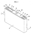
- FIG. 1 is a perspective view illustrating a rechargeable battery according to the first exemplary embodiment of the present invention.
- FIG. 2 is a cross-sectional view of FIG. 1 taken along the line II - II.
- a rechargeable battery 100 according to the first exemplary embodiment includes an electrode assembly 10, a case 15 housing the electrode assembly 10, a cap plate 20 connected to an opening of the case 15, a first terminal 21 (hereinafter, a negative electrode terminal) connected to the cap plate 20, and a second terminal 22 (hereinafter, a positive electrode terminal).
- the electrode assembly 10 is formed by disposing a first electrode 11 (hereinafter a negative electrode) and a second electrode 12 (hereinafter a positive electrode) at both sides of a separator 13 which is an insulator and winding the negative electrode 11, the separator 12, and the positive electrode 13 in a jelly roll state. Further, the electrode assembly is assembled by stacking negative electrode and positive electrode formed of a single plate with a separator interleaved therebetween or assembled by folding and stacking the negative electrode, the separator, and the positive electrode in a zigzag manner (not shown).
- the negative electrode 11 and positive electrode 12 include coated regions formed of a metal plate current collector coated with active material and uncoated regions 11a and 12a formed of an exposed current collector where active material is not coated.
- the uncoated region 11a of the negative electrode 11 is formed at one end of the negative electrode 11 along the winded negative electrode 11.
- the uncoated region 12a of the positive electrode 12 is formed at one end of the positive electrode 12 along the winded positive electrode 12.
- the uncoated regions 11a and 12a are disposed at the both ends of the electrode assembly 10.
- the case 15 is formed in a shape of a cuboid to form an internal space for housing the electrode assembly 10 and electrolyte solution and includes an opening at one side of the cuboid to connect the outside and the inside. The opening permits the electrode assembly 10 to be inserted inside the case 15.
- the cap plate 20 is formed of a thin plate.
- the cap plate 20 is installed at the opening of the case for closing and sealing the case 15.
- the cap plate 20 further includes an electrolyte solution inlet 29 and a vent hole 24.
- the electrolyte solution inlet 29 permits injecting electrolyte solution inside the case 15 after connecting the cap plate 20 to the case 15. After injecting the electrolyte solution, the electrolyte solution inlet 29 is sealed with a sealing stopper 27.
- the vent hole 24 permits discharging of internal pressure of the rechargeable battery 100.
- the vent hole 24 is closed and sealed with the vent plate 25.
- the vent plate 25 is opened when the internal pressure of the rechargeable battery 100 reaches at a predetermined pressure.
- the vent plate 25 includes a notch 25a to lead opening.
- the negative electrode terminal 21 and the positive electrode terminal 22 are installed by penetrating the cap plate 20 and are electrically connected to the electrode assembly 10. That is, the negative electrode terminal 21 is electrically connected to the negative electrode 11 of the electrode assembly 10, and the positive electrode terminal 22 is electrically connected to the positive electrode 12. Therefore, the electrode assembly 10 draws out to the outside of the case 15 through the negative electrode terminal 21 and the positive electrode terminal 22.
- the negative electrode terminal 21 includes a column unit 21 a installed at a terminal hole of the cap plate 20, a flange 21b formed from an inner side of the case 15 at the column unit 21a and a terminal plate 21d disposed at an outer side of the case 15 and connected to the column 21 a.
- a negative electrode gasket 36 is installed between the column unit 21a of the negative electrode terminal 21 and an inner side of the terminal hole of the cap plate 20, thereby sealing between the column 21a of the negative electrode terminal 21 and the cap plate 20.
- the negative electrode gasket 36 further extends between the flange 21b and the cap plate 20, thereby further sealing the flange 21b and the cap plate 20. That is, the negative electrode gasket 36 prevents electrolyte solution from leaking through the terminal hole by installing the negative electrode terminal at the cap plate 20.
- the negative electrode lead tab 31 electrically connects the negative electrode terminal 21 to the negative electrode 11 of the electrode assembly 10. That is, the negative electrode lead tab 31 is connected to a lower end of the column unit 21a for caulking the lower end. The negative electrode lead tab 31 is connected to the lower end of the column unit 21a while being supported at the flange 21b.
- the negative electrode insulating member 41 is installed between the negative electrode lead tab 31 and the cap plate 20 and electrically insulates the negative electrode lead tab 31 and the cap plate 20.
- FIG. 3 is a cross-sectional view illustrating a separation state of a short-circuit tab and a deformable plate in the rechargeable battery of FIG. 1 .
- FIG. 4 is a cross-sectional view illustrating a short-circuit state of the short-circuit tab and the deformable plate in the rechargeable battery of FIG. 1 .
- the rechargeable battery 100 according to the first exemplary embodiment includes an external short-circuit unit installed at the negative electrode terminal 21.
- the external short-circuit unit short-circuits the negative electrode 11 and the positive electrode 12 from the outside of the case 15 when the internal pressure increases.
- the external short-circuit unit includes a short-circuit tab 51 and a deformable plate 53, which are separated or short-circuited according to the internal pressure.
- the short-circuit tab 51 is disposed at the outside of the cap plate 20 by being electrically connected to the negative electrode terminal 21.
- the short-circuit tab 51 penetrates the column unit 21a from the outside of the case 15 and is stacked with the terminal plate 21d.
- the insulating member 37 is installed between the short-circuit tab 51 and the cap plate 20 and electrically insulates the short-circuit tab 51 and the cap plate 20.
- the cap plate 20 is electrically connected to the positive electrode terminal 22.
- the insulating member 37 further extends between the column unit 21a of the negative electrode terminal 21 and an inner side of the terminal hole of the cap plate 20 from the upper part of the negative electrode gasket 36, thereby further electrically insulating between the column unit 21a of the negative electrode terminal 21 and the cap plate 20.
- the short-circuit tab 51 and the terminal plate 21d are connected to an upper part of the column unit 21a by caulking the upper part by stacking and coupling the short-circuit tab 51 and the terminal plate 21d at the upper part of the column unit 21a of the negative electrode terminal 21. Therefore, the short-circuit tab 51 and the terminal plate 21d are supported by the cap plate 20 with the insulating member 37 interleaved.
- the deformable plate 53 is deformed and contacts the short-circuit tab 51 when the internal pressure of the rechargeable battery 100 increases. Therefore, the short-circuit tab 51 is electrically connected to the cap plate 21 so as to maintain the short-circuit state of the electrode assembly 10.
- the deformable plate 53 is installed at a short-circuit hole of the cap plate 20.
- the short-circuit tab 51 is connected to the negative electrode terminal 21 and extends toward the deformable plate 53.
- the short-circuit tab 51 and the deformable plate 53 face each other and sustain a separation state (see FIG. 3 ) or a short-circuit state (see FIG. 4 ).
- the deformable plate 53 is disposed between the insulating member 37 and the cap plate 20 in the short-circuit hole 23.
- the deformable plate 53 is formed to have an arc shaped cross-section to be convex toward the inner side of the case 15 and electrically connected to the cap plate 20.
- the deformable plate 53 When the internal pressure of the case 15 increases, the deformable plate 53 is reversed and protruded to the outer surface of the cap plate 20 through the short-circuit hole 23 (see FIG. 4 ).
- the deformable plate 53 is connected to the short-circuit tab 51 and the short-circuit tab 51 is electrically connected to the cap plate 20. That is, the negative electrode 11 of the electrode assembly 10 is short-circuited from the positive electrodes 12.
- the positive electrode 11 and the negative electrode 21 are short-circuited, a large amount of current instantly flows between the negative electrode terminal 21 and the positive electrode terminal 22 through the short-circuit tab 21 and the positive electrode terminal 22. Accordingly, the electrode assembly 10 is discharged.
- the rechargeable battery 10 of the first exemplary embodiment further includes a structure that improves pass characteristic by reducing the external short-circuit current passing through the electrode assembly 10.
- the rechargeable battery 100 according to the first exemplary embodiment has a configuration increasing an external short-circuit resistance value in order to reduce the external short-circuit current.
- the rechargeable battery 100 further includes a resistance member 70 disposed on an electric connection path of the deformable plate 53 and the positive electrode terminal 22.
- the resistance member 70 has a further higher electrical resistance value than other constituent elements of the other electric connection path.
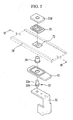
- FIG. 5 is a perspective view illustrating a disassemble state of a positive electrode terminal and a cap plate in the rechargeable battery of FIG. 1 .
- the positive electrode terminal 22 includes a column unit 22a installed at a terminal hole of the cap plate 20, a flange 22b formed at the column unit 22a inside the case 15, and a resistance member 70 and a terminal plate 22d stacked and coupled at, preferably directly coupled at the column unit 22a by being disposed outside the case 15.
- the positive electrode gasket 39 is installed between the column unit 22a of the positive electrode terminal 22 and an inner side of a terminal hole of the cap plate 20 and sealing the column unit 22a of the positive electrode terminal 22 and the cap plate 20.
- the positive electrode gasket 39 further extends between the flange 22b and the cap plate 20, thereby further sealing between the flange 22b and the cap plate 20.
- the positive electrodes gasket 39 further extends between the column unit 22a of the positive electrode terminal 22 and an inner side of a hole of the resistance member 70, thereby sealing between the column unit 22a of the positive electrode terminal 22 and an inner side of a hole of the resistance member 70. That is, the positive electrodes gasket 39 prevents electrolyte solution from leaking through a terminal hole by installing the positive electrode terminal 22 at the cap plate 20.
- the positive electrode lead tab 32 electrically connects the positive electrode terminal 22 to the electrode assembly 10. That is, the positive electrode lead tab 32 is coupled to the lower end of the column unit 22a for caulking the lower end. Accordingly, the positive electrode lead tab 32 is coupled to the lower end of the column 22a while being supported by the flange 22b.
- the positive electrode insulating member 42 is disposed between the positive electrode lead tab 32 and the cap plate 20 and electrically insulating the positive electrode lead tab 32 and the cap plate 20.
- FIG. 6 is a cross-sectional view of FIG. 5 taken along the line VI-VI.
- the resistance member 70 and terminal plate 22d are connected to an upper end of the column unit 22a by stacking and connecting the resistance member 70 and the terminal plate 22d at the upper end of the column unit 22a of the positive electrode terminal 22 for caulking the upper end. Therefore, the resistance member 70 and the terminal plate 22d are supported by the cap plate 20.
- the resistance member 70 electrically connects the cap plate 20 and the column unit 22a.
- the resistance member 70 includes a downward protrusion 71 facing the cap plate 20 and an upward protrusion 73 facing the terminal plate 22d.
- the downward protrusion 71 is coupled at, preferably directly at a groove 72 of the cap plate 20 and the upward protrusion 73 is coupled to, preferably directly to a groove 74 of the terminal plate 22d in a state of the positive electrode terminal 22 assembled at the cap plate 20.
- the downward protrusion 71 and the groove 72 facilitate setting up an installation location of the resistance member 70 on the cap plate 20.
- the upward protrusion 73 and the groove 74 facilitate setting up an installation location of the terminal plate 22d on the resistance member 70.
- the deformable plate 53 and the positive electrode terminal 22 form an electric connection path therebetween through the cap plate 20 and the resistance member 70.
- the resistance member 70 increases the external short-circuit resistance value between the negative electrode terminal 21 and the positive electrode terminal 22 without influencing the output through the negative electrode terminal 21 and the positive electrode terminal 22, thereby reducing the external short-circuit current.
- the resistance member 70 has a resistance value higher than that of the column unit 22a, the terminal plate 22d, and the cap plate 20.
- the terminal plate 22d is formed of aluminum
- the resistance member 70 is formed of stainless steel or steel or nickel alloy.
- a first electric connection path L1 is formed between the column unit 22a of the positive electrode terminal 22 and the terminal plate 22d (see L1 of FIG. 6 ).
- the resistance member 70 does not influence the output of the rechargeable battery in spite of a high resistance value.
- the second electric connection path L2 is formed through the column unit 22a of the positive electrode terminal 22, the terminal plate 22d, the resistance member 70, and the cap plate 20 (see L2 of FIG. 6 ).
- the resistance member 70 reduces the external short-circuit current by increasing the external short-circuit resistance value of the externally short-circuited rechargeable battery 100. Therefore, the penetration characteristic of the external short-circuit current may be stabilized.
- the external short-circuit current penetrates the electrode assembly 10.
- FIG. 7 is a cross-sectional view illustrating a connection state of a positive electrode terminal and a cap plate in a rechargeable battery according to the second exemplary embodiment of the present invention.
- a resistance member 270 of a rechargeable battery 200 includes a main body 271 made of stainless steel or steel or nickel alloy and a plating layer 272 formed on a surface of the main body 271.
- a plating layer 272 may be made of nickel (Ni) and tin (Sn).
- the plating layer 272 prevents the main body 271 from corroding.
- the outer surface of the resistance member 270 may be at least partially covered by, preferably fully covered by the plating layer 272.
- the first electric connection path L1 is formed between the column unit 22a of the positive electrode terminal 22 and the terminal plate 22d.
- the main body 271 and the plating layer 272 do not influence the output of the normally operating rechargeable battery 200 although the main body 271 and the plating layer 272 have an electrical resistance value higher than the column unit 22a, the terminal plate 22d, and the cap plate 20.
- the second electric connection path L2 is formed through the column unit 22a of the positive electrode terminal 22, the terminal plate 22d, the main body 271, the plating layer 272, and the cap plate 20.
- the main body 271 and the plating layer 272 reduces the external short-circuit current by increasing the external short-circuit resistance value of the externally short-circuited rechargeable battery 200. Therefore, the penetration characteristic of the external short-circuit current penetrating the electrode assembly 10 is stabilized.
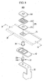
- FIG. 8 is a perspective view illustrating a disassemble state of a positive electrode terminal and a cap plate in a rechargeable battery according to the third exemplary embodiment of the present invention.
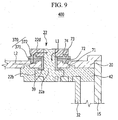
- FIG. 9 is a cross-sectional view of FIG. 8 taken along the line IX-IX.
- a resistance member 270 of a rechargeable battery 400 according to the third exemplary embodiment includes a first resistance unit 371 and a second resistance unit 372 made of different materials.
- the first resistance unit 371 may be made of aluminum
- the second resistance unit 372 may be made of stainless steel having an electrical resistance value higher than that of the first resistance unit 371.
- the second resistance unit 372 has an electrical resistance value higher than the electrical resistance values of the column unit 22a, the terminal plate 22d, and the cap plate 20.
- the first and second resistance units 371 and 372 may be made of stainless steel and aluminum, respectively.
- the first resistance unit 371 is connected to the cap plate 20 through a downward protrusion 71 facing the cap plate 20.
- the second resistance unit 372 is coupled to, preferably directly to the terminal plate 22d through an upward protrusion 73 facing the terminal plate 22d.
- the downward protrusion 71 and the groove 72 facilitate an installation location of the first resistance unit 371 on the cap plate 20.
- the upward protrusion 73 and the groove 74 facilitate an installation location of the terminal plate 22d on the second resistance unit 372.
- the first electric connection path L1 is formed between the column unit 22a of the positive electrode terminal 22 and the terminal plate 22d when the rechargeable battery 400 normally operates.
- the first and second resistance units 371 and 372 do not influence the output of the normally operating rechargeable battery 400 in spite of high electrical resistance value.
- the second electric connection path L2 is formed through the column unit 22a of the positive electrode terminal 22, the terminal plate 22d, the first and second resistance units 371 and 372, and the cap plate 20.
- the first and second resistance units 371 and 372 reduce the external short-circuit current by increasing the external short-circuit resistance value of the externally short-circuited rechargeable battery 400. Accordingly, the penetration characteristic of the external short-circuit current penetrating the electrode assembly 10 may be stabilized.
- the outer surfaces of the two resistance units may also be covered by a plating layer as described in a previous embodiment or by two plating layers.
Landscapes
- Chemical & Material Sciences (AREA)
- Chemical Kinetics & Catalysis (AREA)
- Electrochemistry (AREA)
- General Chemical & Material Sciences (AREA)
- Engineering & Computer Science (AREA)
- Manufacturing & Machinery (AREA)
- Connection Of Batteries Or Terminals (AREA)
- Sealing Battery Cases Or Jackets (AREA)
- Secondary Cells (AREA)
Claims (14)
- Wiederaufladbare Batterie (100), umfassend:eine Elektrodenanordnung (10) umfassend eine erste Elektrode (11), eine zweite Elektrode (12) sowie einen Separator (13) zwischen der ersten Elektrode (11) und der zweiten Elektrode (12),ein Gehäuse (15) zum Aufnehmen der Elektrodenanordnung (10) in diesem,eine Abdeckplatte (20) zum Verschließen einer Öffnung des Gehäuses (15),eine Elektrodenklemme (22), die zur Außenseite des Gehäuses (15) vorsteht und elektrisch mit der zweiten Elektrode (12) verbunden ist, unddadurch gekennzeichnet, dassein einen Kurzschluss hervorrufendes Element vorgesehen ist, umfassend eine verformbare Platte (53), die in einem Kurzschlussloch der Abdeckplatte (20) angebracht ist und ausgebildet ist, über die Abdeckplatte (20) einen Kurzschluss zwischen der Elektrodenklemme (22) und der ersten Elektrode (11) zu erzeugen,undein Widerstandselement (70) an der Außenseite des Gehäuses (15) zwischen der Elektrodenklemme (22) und der Abdeckplatte (20), diese elektrisch verbindend, vorgesehen ist, wobei das Widerstandselement (70) einen elektrischen Widerstand aufweist, der größer als der Widerstand der Abdeckplatte (20) und/oder der Widerstand der Elektrodenklemme (22) ist, wobei die Elektrodenklemme (22) eine über der Abdeckplatte (20) vorgesehene Klemmenplatte (22d) umfasst, und wobei das Widerstandselement (70) zwischen der Abdeckplatte (20) und der Klemmenplatte (22d) vorgesehen ist.
- Wiederaufladbare Batterie (100) nach Anspruch 1, wobei die Elektrodenklemme (22) ferner eine aus der Abdeckplatte (20) vorstehende Säuleneinheit (22a) umfasst, mit einem an der Säuleneinheit (22a) innerhalb des Gehäuses (15) ausgebildeten Flansch (22b), und wobei die Klemmenplatte (22d) mit der Säuleneinheit (22a) verbunden ist.
- Wiederaufladbare Batterie (100) nach einem der vorstehenden Ansprüche, wobei die Elektrodenklemme (22) ferner eine zwischen der Säuleneinheit (22a) und der Abdeckplatte (20) angebrachte Dichtung (39) umfasst, wobei das Widerstandselement (70) an der Säuleneinheit (22a) vorgesehen ist und durch die Dichtung (39) elektrisch von der Säuleneinheit (22a) getrennt ist.
- Wiederaufladbare Batterie (100) nach einem der vorstehenden Ansprüche, wobei das Widerstandselement (70) einen der Klemmenplatte (22d) zugewandten ersten Vorsprung (73) umfasst und die Klemmenplatte (22d) eine dem ersten Vorsprung (73) entsprechende erste Aussparung (74) umfasst.
- Wiederaufladbare Batterie (100) nach einem der vorstehenden Ansprüche, wobei das Widerstandselement (70) einen der Abdeckplatte (20) zugewandten zweiten Vorsprung (71) umfasst, wobei die Abdeckplatte (20) eine dem zweiten Vorsprung (71) entsprechende zweite Aussparung (72) umfasst.
- Wiederaufladbare Batterie (100) nach einem der vorstehenden Ansprüche, wobei das Widerstandselement (70) einen Widerstandswert aufweist, der höher ist als der von mindestens einem der Säuleneinheit (22a), der Klemmenplatte (22d) und der Abdeckplatte (20).
- Wiederaufladbare Batterie (100) nach einem der vorstehenden Ansprüche, wobei das Widerstandselement (70) aus Edelstahl oder Stahl oder Nickellegierung gebildet ist.
- Wiederaufladbare Batterie (100) nach einem der vorstehenden Ansprüche, wobei das Widerstandselement (270) einen Hauptkörper (271) und eine Überzugsschicht (272) umfasst, wobei die Überzugsschicht das Äußere des Hauptkörpers (271) zumindest teilweise bedeckt.
- Wiederaufladbare Batterie (100) nach Anspruch 8, wobei der Hauptkörper (271) aus Stahl oder Edelstahl oder Nickellegierung besteht, und die Überzugsschicht (272) aus Nickel oder Zinn besteht.
- Wiederaufladbare Batterie (100) nach einem der Ansprüche 1 bis 7, wobei das Widerstandselement (370) eine erste Widerstandseinheit (371) und eine zweite Widerstandseinheit (372) umfasst, wobei die erste und die zweite Widerstandseinheit (371, 372) unterschiedliche elektrische Widerstandswerte aufweisen.
- Wiederaufladbare Batterie (100) nach Anspruch 10, wobei die erste Widerstandseinheit (371) und die zweite Widerstandseinheit (372) übereinander angebracht sind, wobei die erste Widerstandseinheit (371) mit der Abdeckplatte (20) verbunden ist und die zweite Widerstandseinheit (372) mit der Klemmenplatte (22d) verbunden ist.
- Wiederaufladbare Batterie (100) nach Anspruch 10 oder 11, wobei die zweite Widerstandseinheit (372) einen elektrische Widerstand aufweist, der höher ist als der der ersten Widerstandseinheit (371).
- Wiederaufladbare Batterie (100) nach einem der vorstehenden Ansprüche, wobei das einen Kurzschluss hervorrufende Element eine Kurzschlussfahne (51) umfasst, die über der Abdeckplatte (20) angeordnet ist, sowie eine verformbare Platte (53), die an der Abdeckplatte (20) befestigt und mit dem Inneren des Gehäuses (15) in Verbindung steht.
- Wiederaufladbare Batterie (100) nach Anspruch 13, wobei unter normalen Druckbedingungen unterhalb eines eingestellten Druckschwellenwertes die verformbare Platte (53) eine erste Konfiguration aufweist, in der sie innerhalb des Gehäuses (15) vorspringt, und bei Überschreiten des eingestellten Druckschwellenwertes innerhalb des Gehäuses (15) eine zweite Konfiguration aufweist, in der sie außerhalb des Gehäuses (15) vorspringt und die Kurzschlussfahne (51) kontaktiert, um einen Kurzschluss zwischen den ersten und zweiten Elektroden (11, 12) über die Abdeckplatte (20) und das Widerstandsglied (70) zu erzeugen.
Applications Claiming Priority (2)
| Application Number | Priority Date | Filing Date | Title |
|---|---|---|---|
| US41922110P | 2010-12-02 | 2010-12-02 | |
| US13/077,640 US9478774B2 (en) | 2010-12-02 | 2011-03-31 | Rechargeable battery |
Publications (2)
| Publication Number | Publication Date |
|---|---|
| EP2461393A1 EP2461393A1 (de) | 2012-06-06 |
| EP2461393B1 true EP2461393B1 (de) | 2014-05-14 |
Family
ID=45563639
Family Applications (1)
| Application Number | Title | Priority Date | Filing Date |
|---|---|---|---|
| EP11165265.7A Active EP2461393B1 (de) | 2010-12-02 | 2011-05-09 | Wiederaufladbare Batterie |
Country Status (5)
| Country | Link |
|---|---|
| US (1) | US9478774B2 (de) |
| EP (1) | EP2461393B1 (de) |
| JP (1) | JP5481443B2 (de) |
| KR (1) | KR101244738B1 (de) |
| CN (1) | CN102487135B (de) |
Families Citing this family (51)
| Publication number | Priority date | Publication date | Assignee | Title |
|---|---|---|---|---|
| KR101233470B1 (ko) * | 2011-01-25 | 2013-02-15 | 로베르트 보쉬 게엠베하 | 이차 전지 |
| KR101666870B1 (ko) * | 2012-03-20 | 2016-10-17 | 삼성에스디아이 주식회사 | 저항부재를 가지는 이차 전지 |
| US9461295B2 (en) * | 2012-05-04 | 2016-10-04 | Samsung Sdi Co., Ltd. | Rechargeable battery including terminal portion having auxiliary plate for reducing current flow along short circuit current path |
| JP6194572B2 (ja) * | 2012-10-15 | 2017-09-13 | 株式会社Gsユアサ | 蓄電素子及び電源モジュール |
| US10367186B2 (en) * | 2013-01-18 | 2019-07-30 | Samsung Sdi Co., Ltd. | Secondary battery including an insulating member |
| US20140227567A1 (en) * | 2013-02-14 | 2014-08-14 | Samsung Sdi Co., Ltd. | Battery module |
| CN103208595B (zh) * | 2013-03-25 | 2017-02-08 | 东莞新能源科技有限公司 | 一种铝壳动力电池用顶盖 |
| KR101579348B1 (ko) | 2013-07-26 | 2015-12-22 | 주식회사 엘지화학 | 배터리 스웰링 감지 장치 및 방법 |
| KR101711988B1 (ko) | 2013-09-12 | 2017-03-03 | 삼성에스디아이 주식회사 | 이차 전지 |
| KR101724006B1 (ko) | 2013-09-13 | 2017-04-06 | 삼성에스디아이 주식회사 | 이차 전지 |
| KR101711983B1 (ko) | 2013-09-16 | 2017-03-08 | 삼성에스디아이 주식회사 | 이차 전지 |
| KR101720619B1 (ko) * | 2013-10-08 | 2017-03-28 | 삼성에스디아이 주식회사 | 이차전지 |
| KR101601151B1 (ko) | 2013-10-17 | 2016-03-08 | 주식회사 엘지화학 | 못이 이차전지를 관통했을 때의 과전류 시뮬레이션 방법 및 그 프로그램을 저장한 기록매체 |
| CN203644834U (zh) * | 2013-11-11 | 2014-06-11 | 宁德新能源科技有限公司 | 一种动力电池安全顶盖 |
| US9495493B2 (en) | 2013-11-25 | 2016-11-15 | Lg Chem, Ltd. | Overcurrent simulation method when nail penetrates secondary battery and recording medium storing the program |
| KR102154331B1 (ko) * | 2014-02-14 | 2020-09-09 | 삼성에스디아이 주식회사 | 이차 전지 |
| JP6296153B2 (ja) * | 2014-05-12 | 2018-03-20 | 株式会社豊田自動織機 | 蓄電装置 |
| KR102164009B1 (ko) * | 2014-05-28 | 2020-10-13 | 삼성에스디아이 주식회사 | 이차 전지 |
| KR102283793B1 (ko) | 2014-08-08 | 2021-07-30 | 삼성에스디아이 주식회사 | 이차 전지 |
| KR102282244B1 (ko) | 2014-09-29 | 2021-07-28 | 삼성에스디아이 주식회사 | 이차 전지 |
| CN110165094B (zh) * | 2015-01-12 | 2021-12-28 | 东莞新能安科技有限公司 | 动力电池顶盖 |
| KR102368085B1 (ko) | 2015-03-03 | 2022-02-24 | 삼성에스디아이 주식회사 | 연결부재를 갖는 이차 전지 |
| JP6241676B2 (ja) * | 2015-03-27 | 2017-12-06 | トヨタ自動車株式会社 | 密閉型電池 |
| KR102412027B1 (ko) * | 2015-06-23 | 2022-06-22 | 삼성에스디아이 주식회사 | 이차 전지 |
| KR102373538B1 (ko) | 2015-07-14 | 2022-03-10 | 삼성에스디아이 주식회사 | 이차 전지 |
| CN104966809A (zh) * | 2015-07-20 | 2015-10-07 | 天津市捷威动力工业有限公司 | 一种具有壳体带电功能的锂离子电池 |
| CN105098131A (zh) * | 2015-07-20 | 2015-11-25 | 天津市捷威动力工业有限公司 | 一种具有盖板带电功能的锂离子电池极柱 |
| CN106935740B (zh) * | 2015-07-23 | 2019-12-20 | 宁德时代新能源科技股份有限公司 | 动力电池顶盖结构及动力电池 |
| US10763487B2 (en) * | 2015-07-23 | 2020-09-01 | Contemporary Amperex Technology Co., Limited | Power battery cap structure and power battery |
| KR102392380B1 (ko) * | 2015-08-19 | 2022-04-29 | 삼성에스디아이 주식회사 | 이차전지 |
| KR101826141B1 (ko) * | 2015-08-28 | 2018-02-06 | 삼성에스디아이 주식회사 | 이차 전지 팩 |
| KR102470495B1 (ko) | 2015-11-24 | 2022-11-24 | 삼성에스디아이 주식회사 | 이차전지 및 그 제조방법 |
| JP6631835B2 (ja) * | 2016-03-22 | 2020-01-15 | トヨタ自動車株式会社 | 二次電池 |
| CN105762307B (zh) * | 2016-04-26 | 2018-05-22 | 宁德时代新能源科技股份有限公司 | 二次电池顶盖和二次电池 |
| JP6996505B2 (ja) * | 2016-06-29 | 2022-01-17 | 三洋電機株式会社 | 二次電池 |
| KR102204700B1 (ko) * | 2016-07-15 | 2021-01-18 | 삼성에스디아이 주식회사 | 이차 전지 |
| JP6888934B2 (ja) * | 2016-09-29 | 2021-06-18 | トヨタ自動車株式会社 | 二次電池 |
| WO2018090180A1 (zh) * | 2016-11-15 | 2018-05-24 | 宁德时代新能源科技股份有限公司 | 二次电池 |
| WO2018090179A1 (zh) * | 2016-11-15 | 2018-05-24 | 宁德时代新能源科技股份有限公司 | 二次电池 |
| CN106450063B (zh) * | 2016-11-15 | 2019-07-19 | 宁德时代新能源科技股份有限公司 | 二次电池 |
| CN106450137B (zh) * | 2016-11-15 | 2019-02-22 | 宁德时代新能源科技股份有限公司 | 二次电池 |
| CN108075055B (zh) | 2016-11-16 | 2021-05-07 | 宁德时代新能源科技股份有限公司 | 动力电池顶盖结构及动力电池 |
| JP6859851B2 (ja) * | 2017-05-31 | 2021-04-14 | 三洋電機株式会社 | 角形二次電池、それを用いた組電池及び車両 |
| CN109285974B (zh) * | 2017-07-20 | 2021-08-03 | 宁德时代新能源科技股份有限公司 | 二次电池顶盖组件及二次电池 |
| CN110176557B (zh) * | 2019-04-09 | 2024-04-05 | 宁德时代新能源科技股份有限公司 | 二次电池及其顶盖组件 |
| CN113054295B (zh) * | 2019-12-26 | 2022-08-09 | 比亚迪股份有限公司 | 盖板组件、电池、电池模组、动力电池包和电动汽车 |
| CN113054330A (zh) * | 2019-12-26 | 2021-06-29 | 比亚迪股份有限公司 | 电池模组和具有其的动力电池包、电动汽车 |
| CN112993494A (zh) * | 2021-04-16 | 2021-06-18 | 湖北亿纬动力有限公司 | 一种电池顶盖以及电池 |
| KR20230085544A (ko) | 2021-12-07 | 2023-06-14 | 삼성에스디아이 주식회사 | 이차전지 |
| KR20230100114A (ko) * | 2021-12-28 | 2023-07-05 | 삼성에스디아이 주식회사 | 이차 전지 |
| KR20250034710A (ko) * | 2023-09-04 | 2025-03-11 | 동양피스톤 주식회사 | 캡 플레이트 어셈블리, 캡 플레이트 어셈블리의 제조 방법 및 이를 포함하는 배터리 셀 |
Family Cites Families (118)
| Publication number | Priority date | Publication date | Assignee | Title |
|---|---|---|---|---|
| US4209571A (en) | 1975-08-28 | 1980-06-24 | Gte Laboratories Incorporated | Primary electrochemical cell |
| US4879187A (en) | 1987-10-22 | 1989-11-07 | Eveready Battery Company | Battery terminal fuse |
| US5143860A (en) | 1987-12-23 | 1992-09-01 | Texas Instruments Incorporated | High density EPROM fabricaiton method having sidewall floating gates |
| US4945014A (en) | 1988-02-10 | 1990-07-31 | Mitsubishi Petrochemical Co., Ltd. | Secondary battery |
| JPH0562664A (ja) | 1991-09-02 | 1993-03-12 | Matsushita Electric Ind Co Ltd | 防爆型非水二次電池 |
| JPH05251290A (ja) | 1992-03-07 | 1993-09-28 | Hitachi Aic Inc | ケース入りコンデンサ |
| JPH05275088A (ja) | 1992-03-27 | 1993-10-22 | Yuasa Corp | 積層薄形電池 |
| JP3232767B2 (ja) | 1993-03-31 | 2001-11-26 | 株式会社デンソー | 安全機構付き化学電池 |
| US5523178A (en) * | 1992-12-14 | 1996-06-04 | Nippondenso Co., Ltd. | Chemical cell |
| JPH0737572A (ja) | 1993-07-22 | 1995-02-07 | Japan Storage Battery Co Ltd | リチウム電池 |
| JP3573293B2 (ja) * | 1993-11-24 | 2004-10-06 | 日本電池株式会社 | 電池 |
| JPH0850920A (ja) | 1994-08-08 | 1996-02-20 | Toyo Takasago Kandenchi Kk | 角型リチウム二次電池 |
| US5707756A (en) | 1994-11-29 | 1998-01-13 | Fuji Photo Film Co., Ltd. | Non-aqueous secondary battery |
| JPH08185850A (ja) | 1994-12-27 | 1996-07-16 | Sony Corp | リチウムイオン二次電池 |
| JPH09106804A (ja) | 1995-10-09 | 1997-04-22 | Wako Denshi Kk | 電池の安全装置 |
| JPH1074500A (ja) | 1996-08-30 | 1998-03-17 | Sanyo Electric Co Ltd | 密閉型電池及びその製造方法 |
| TW332342B (en) | 1996-11-11 | 1998-05-21 | Mos Electronics Taiwan Inc | Structure and fabrication method of split-gate flash memory |
| JPH10188946A (ja) | 1996-12-20 | 1998-07-21 | Toyo Takasago Kandenchi Kk | 内部短絡保護装置を有する角形電池 |
| JP3464750B2 (ja) | 1997-01-21 | 2003-11-10 | 東芝電池株式会社 | リチウム二次電池 |
| US5800937A (en) | 1997-05-02 | 1998-09-01 | Motorola, Inc. | Current interrupt device for secondary batteries |
| US6069551A (en) | 1997-05-02 | 2000-05-30 | Therm-O-Disc, Incorporated | Thermal switch assembly |
| JPH10326610A (ja) | 1997-05-27 | 1998-12-08 | Hitachi Ltd | 非水電解液二次電池 |
| JPH117931A (ja) | 1997-06-18 | 1999-01-12 | Hitachi Ltd | 二次電池 |
| JPH1140203A (ja) * | 1997-07-14 | 1999-02-12 | Hitachi Ltd | 二次電池 |
| JPH11191436A (ja) | 1997-12-26 | 1999-07-13 | Hitachi Ltd | 蓄電保護器 |
| KR200283452Y1 (ko) | 1997-12-30 | 2002-09-19 | 삼성에스디아이 주식회사 | 비수용액계 이차 전지 |
| TW502467B (en) * | 1998-03-18 | 2002-09-11 | Toshiba Battery | Battery, lead member for battery connection, and battery pack using the same |
| JP4303801B2 (ja) | 1998-03-25 | 2009-07-29 | ワコー電子株式会社 | 二次電池の安全装置 |
| JPH11307076A (ja) | 1998-04-24 | 1999-11-05 | Sony Corp | 二次電池 |
| JP3497380B2 (ja) | 1998-06-02 | 2004-02-16 | 日本碍子株式会社 | リチウム二次電池 |
| KR100270958B1 (ko) | 1998-07-10 | 2000-11-01 | 윤종용 | 비휘발성 반도체 소자 및 그 제조방법 |
| DE19837909C2 (de) | 1998-08-20 | 2001-05-17 | Implex Hear Tech Ag | Schutzvorrichtung für eine mehrfach nachladbare elektrochemische Batterie |
| JP2000082457A (ja) | 1998-09-04 | 2000-03-21 | Toyo Kohan Co Ltd | 電気電子機器・部品用安全装置、それを用いた密閉型電池の安全装置及びそれを用いた密閉型電池 |
| JP2000182598A (ja) | 1998-12-16 | 2000-06-30 | Hitachi Ltd | 非水電解液二次電池およびその熱動継電器 |
| KR100358062B1 (ko) | 1998-12-30 | 2003-01-24 | 주식회사 하이닉스반도체 | 플래쉬메모리셀및그의제조방법 |
| JP2000235872A (ja) | 1999-02-16 | 2000-08-29 | Alps Electric Co Ltd | 電池の感圧電路遮断機構 |
| JP3693844B2 (ja) | 1999-03-01 | 2005-09-14 | アルプス電気株式会社 | 電池の感圧電路遮断機構 |
| FR2796205B1 (fr) | 1999-07-08 | 2001-10-05 | Cit Alcatel | Accumulateur electrochimique etanche comportant un dispositif de reprise de courant en aluminium |
| KR100358224B1 (ko) | 1999-07-31 | 2002-10-25 | 주식회사 엘지화학 | 리튬 이차전지 |
| US6342826B1 (en) * | 1999-08-11 | 2002-01-29 | Therm-O-Disc, Incorporated | Pressure and temperature responsive switch assembly |
| US6525371B2 (en) | 1999-09-22 | 2003-02-25 | International Business Machines Corporation | Self-aligned non-volatile random access memory cell and process to make the same |
| KR100349908B1 (ko) | 1999-12-15 | 2002-08-22 | 삼성에스디아이 주식회사 | 각형 밀폐전지 |
| JP2001202946A (ja) | 2000-01-18 | 2001-07-27 | Nec Corp | 非水電解液二次電池 |
| JP2001357834A (ja) | 2000-06-16 | 2001-12-26 | Japan Storage Battery Co Ltd | 電 池 |
| KR100346386B1 (ko) | 2000-09-18 | 2002-08-01 | 삼성에스디아이 주식회사 | 이차전지의 안전장치 |
| JP2002216743A (ja) | 2001-01-19 | 2002-08-02 | Alps Electric Co Ltd | 電池用圧力遮断センサ |
| FR2821983B1 (fr) | 2001-03-07 | 2003-08-15 | Schneider Electric Ind Sa | Dispositif de raccordement pour accumulateur electrique |
| TW480680B (en) | 2001-04-03 | 2002-03-21 | Nanya Technology Corp | Method for producing self-aligned separated gate-type flash memory cell |
| US6730430B2 (en) | 2001-07-09 | 2004-05-04 | Nan Ya Plastics Corporation | Explosion-proof safety structure for column shape lithium battery |
| CN1252843C (zh) | 2001-07-11 | 2006-04-19 | 能元科技股份有限公司 | 方形电池的安全保护结构 |
| JP4645001B2 (ja) | 2001-07-11 | 2011-03-09 | 株式会社Gsユアサ | 電池 |
| JP4154136B2 (ja) | 2001-08-06 | 2008-09-24 | 松下電器産業株式会社 | 角形密閉式電池 |
| JP2003051304A (ja) | 2001-08-07 | 2003-02-21 | Matsushita Electric Ind Co Ltd | 非水電解質二次電池 |
| US20040170887A1 (en) | 2001-08-07 | 2004-09-02 | Kenjin Masumoto | Non-aqueous electrolytic secondary battery |
| KR100420146B1 (ko) | 2001-10-18 | 2004-03-02 | 삼성에스디아이 주식회사 | 서모 프로텍터가 장착된 이차전지 |
| JP2003197178A (ja) | 2001-12-25 | 2003-07-11 | Mitsubishi Heavy Ind Ltd | 二次電池 |
| JP2003223886A (ja) | 2002-01-30 | 2003-08-08 | Sanyo Gs Soft Energy Co Ltd | 電 池 |
| JP2003234055A (ja) | 2002-02-12 | 2003-08-22 | Texas Instr Japan Ltd | 過電圧保護装置およびそれを用いたバッテリー保護システム |
| JP4629952B2 (ja) | 2002-02-13 | 2011-02-09 | パナソニック株式会社 | 二次電池の製造方法 |
| JP4967216B2 (ja) | 2003-12-05 | 2012-07-04 | 株式会社Gsユアサ | 非水電解質電池 |
| JP2004022477A (ja) | 2002-06-20 | 2004-01-22 | Matsushita Electric Ind Co Ltd | 電池 |
| JP2004071265A (ja) * | 2002-08-05 | 2004-03-04 | Sanyo Electric Co Ltd | 電池 |
| JP2004087194A (ja) * | 2002-08-23 | 2004-03-18 | Nok Corp | 封口板 |
| KR100477750B1 (ko) | 2002-09-23 | 2005-03-18 | 삼성에스디아이 주식회사 | 리튬 이온 전지의 전극조립체 및 이를 이용한 리튬이온 전지 |
| JP2004273139A (ja) | 2003-03-05 | 2004-09-30 | Canon Inc | リチウム二次電池 |
| JP4259890B2 (ja) | 2003-03-07 | 2009-04-30 | 三洋電機株式会社 | 密閉形蓄電池 |
| JP2004319463A (ja) * | 2003-03-28 | 2004-11-11 | Matsushita Electric Ind Co Ltd | 二次電池 |
| JP2005032477A (ja) | 2003-07-08 | 2005-02-03 | Toyota Motor Corp | 電池、およびそれを搭載した自動車 |
| JP2005044626A (ja) | 2003-07-22 | 2005-02-17 | Sanyo Gs Soft Energy Co Ltd | 電池 |
| KR100516772B1 (ko) | 2003-08-22 | 2005-09-22 | 삼성에스디아이 주식회사 | 전극탭을 캔의 단변부에 위치시킨 이차전지 |
| JP4953551B2 (ja) | 2003-10-31 | 2012-06-13 | 三洋電機株式会社 | 密閉型電池 |
| US7029968B2 (en) | 2003-12-05 | 2006-04-18 | Taiwan Semiconductor Manufacturing Company, Ltd. | Method of forming a PIP capacitor |
| US7315056B2 (en) | 2004-06-07 | 2008-01-01 | Silicon Storage Technology, Inc. | Semiconductor memory array of floating gate memory cells with program/erase and select gates |
| JP2006012602A (ja) | 2004-06-25 | 2006-01-12 | Japan Storage Battery Co Ltd | 蓄電池 |
| KR100619631B1 (ko) | 2004-08-31 | 2006-09-12 | 주식회사 엘지화학 | 개선된 리튬 이차전지 |
| KR100624919B1 (ko) | 2004-09-22 | 2006-09-15 | 삼성에스디아이 주식회사 | 이차 전지 |
| KR20060039955A (ko) | 2004-11-02 | 2006-05-10 | 유니썸테크놀로지 주식회사 | 배터리용 안전장치 |
| JP4984892B2 (ja) | 2004-11-08 | 2012-07-25 | ソニー株式会社 | 電池およびセンターピン |
| KR100614377B1 (ko) | 2004-11-15 | 2006-08-21 | 삼성에스디아이 주식회사 | 리튬 이차전지 |
| JP2006147180A (ja) | 2004-11-16 | 2006-06-08 | Toshiba Corp | 非水電解質二次電池 |
| CN1655389A (zh) | 2005-03-04 | 2005-08-17 | 北京中信国安盟固利新材料技术研究院有限公司 | 大容量金属外壳锂离子二次电池 |
| KR100614376B1 (ko) | 2005-04-25 | 2006-08-22 | 삼성에스디아이 주식회사 | 캔형 리튬 이차전지 |
| US7946331B2 (en) | 2005-06-14 | 2011-05-24 | Cufer Asset Ltd. L.L.C. | Pin-type chip tooling |
| US7364970B2 (en) | 2005-09-30 | 2008-04-29 | Freescale Semiconductor, Inc. | Method of making a multi-bit non-volatile memory (NVM) cell and structure |
| KR100693115B1 (ko) | 2005-11-08 | 2007-03-12 | 주식회사 비츠로셀 | 퓨즈기능을 갖는 캐소드 리드 |
| KR100878702B1 (ko) | 2005-11-30 | 2009-01-14 | 주식회사 엘지화학 | 이차전지용 안전장치 및 그것을 포함하는 전지팩 |
| JP4848860B2 (ja) | 2006-01-13 | 2011-12-28 | ソニー株式会社 | 電池 |
| KR100878701B1 (ko) * | 2006-03-13 | 2009-01-14 | 주식회사 엘지화학 | 고율 충방전 원통형 이차전지 |
| KR100906253B1 (ko) | 2006-05-01 | 2009-07-07 | 주식회사 엘지화학 | 과전류의 인가시 파괴되는 파단부가 형성되어 있는전극단자를 포함하고 있는 이차전지 |
| JP2008027668A (ja) | 2006-07-19 | 2008-02-07 | Sony Corp | 電池 |
| KR20080025437A (ko) | 2006-09-18 | 2008-03-21 | 주식회사 엘지화학 | 전극단자의 위치조절이 가능하고 안전성이 향상된 이차전지 |
| KR100880321B1 (ko) | 2006-12-14 | 2009-01-28 | 삼성에스디아이 주식회사 | 이차전지 |
| JP4609432B2 (ja) | 2007-01-19 | 2011-01-12 | 住友電気工業株式会社 | ヒューズ付き蓄電デバイス用リード端子及び非水電解質蓄電デバイス |
| JP5271498B2 (ja) | 2007-01-26 | 2013-08-21 | 三菱重工業株式会社 | リチウム二次電池及び組電池 |
| JP2008218132A (ja) | 2007-03-02 | 2008-09-18 | Matsushita Electric Ind Co Ltd | 密閉形電池 |
| KR100870349B1 (ko) | 2007-03-16 | 2008-11-25 | 삼성에스디아이 주식회사 | 보호회로기판의 접속단자 및 그를 이용한 이차전지 |
| KR100922352B1 (ko) | 2007-10-02 | 2009-10-21 | 삼성에스디아이 주식회사 | 이차 전지 |
| JP5314350B2 (ja) | 2008-07-25 | 2013-10-16 | 三菱重工業株式会社 | 電池パック容器及び電池パック |
| JP2010033949A (ja) | 2008-07-30 | 2010-02-12 | Panasonic Corp | 電池 |
| JP5288973B2 (ja) | 2008-09-29 | 2013-09-11 | 三洋電機株式会社 | 角形二次電池及び電池モジュール |
| JP5418809B2 (ja) | 2008-10-16 | 2014-02-19 | 株式会社Gsユアサ | 電池及びその製造方法 |
| KR20100052885A (ko) | 2008-11-11 | 2010-05-20 | 주식회사 하이닉스반도체 | 반도체 메모리 장치 |
| KR101038710B1 (ko) | 2008-11-19 | 2011-06-02 | 한국후지냉기(주) | 내열성이 우수하고 고마찰계수를 갖는 마찰재 및 이의 제조방법과 이를 이용한 습식 마찰재 |
| US8486546B2 (en) | 2008-12-01 | 2013-07-16 | Samsung Sdi Co., Ltd. | Cap assembly and secondary battery using the same with notched vent member |
| KR101023104B1 (ko) | 2008-12-26 | 2011-03-24 | 에스비리모티브 주식회사 | 이차 전지 |
| KR101085894B1 (ko) | 2009-01-29 | 2011-11-23 | 서울대학교산학협력단 | 임프린트 정렬 과정에서의 마찰 감소방법 |
| JP2009105075A (ja) | 2009-02-16 | 2009-05-14 | Gs Yuasa Corporation:Kk | 電池 |
| KR101041153B1 (ko) | 2009-03-04 | 2011-06-13 | 에스비리모티브 주식회사 | 이차전지 및 그 모듈 |
| US8323813B2 (en) | 2009-05-14 | 2012-12-04 | Sb Limotive Co., Ltd. | Rechargeable battery including an extensible member |
| US9246140B2 (en) | 2009-07-09 | 2016-01-26 | Samsung Sdi Co., Ltd. | Rechargeable battery with a cap assembly having a first tab located outside of the case |
| US8236439B2 (en) | 2009-08-14 | 2012-08-07 | Sb Limotive Co., Ltd. | Rechargeable battery |
| US8268478B2 (en) | 2009-08-17 | 2012-09-18 | Sb Limotive Co., Ltd. | Rechargeable battery having anti-vibration member |
| US8877361B2 (en) | 2009-09-01 | 2014-11-04 | Samsung Sdi Co., Ltd. | Rechargeable battery |
| KR101390527B1 (ko) | 2009-09-17 | 2014-04-30 | 주식회사 엘지화학 | Ptc 하이브리드 안전밴트 및 이를 구비하는 이차전지 |
| US8440336B2 (en) | 2009-12-08 | 2013-05-14 | Samsung Sdi Co., Ltd. | Rechargeable battery with short circuit member |
| US8632911B2 (en) | 2010-01-15 | 2014-01-21 | Samsung Sdi Co., Ltd. | Rechargeable battery |
| KR101042808B1 (ko) | 2010-01-26 | 2011-06-20 | 에스비리모티브 주식회사 | 이차 전지 |
| KR101130294B1 (ko) | 2010-03-30 | 2012-08-23 | 에스비리모티브 주식회사 | 이차 전지 |
-
2011
- 2011-03-31 US US13/077,640 patent/US9478774B2/en active Active
- 2011-04-19 KR KR1020110036267A patent/KR101244738B1/ko active Active
- 2011-05-09 EP EP11165265.7A patent/EP2461393B1/de active Active
- 2011-07-19 CN CN201110207662.2A patent/CN102487135B/zh active Active
- 2011-08-04 JP JP2011170959A patent/JP5481443B2/ja active Active
Also Published As
| Publication number | Publication date |
|---|---|
| US9478774B2 (en) | 2016-10-25 |
| KR101244738B1 (ko) | 2013-03-18 |
| CN102487135B (zh) | 2015-10-21 |
| EP2461393A1 (de) | 2012-06-06 |
| JP2012119303A (ja) | 2012-06-21 |
| CN102487135A (zh) | 2012-06-06 |
| US20120141845A1 (en) | 2012-06-07 |
| JP5481443B2 (ja) | 2014-04-23 |
| KR20120060724A (ko) | 2012-06-12 |
Similar Documents
| Publication | Publication Date | Title |
|---|---|---|
| EP2461393B1 (de) | Wiederaufladbare Batterie | |
| EP2624327B1 (de) | Wiederaufladbare Batterie | |
| EP2273587B1 (de) | Wiederaufladbare Batterie | |
| EP2333871B1 (de) | Wiederaufladbare Batterie | |
| EP2533326B1 (de) | Wiederaufladbare Batterie | |
| US9023498B2 (en) | Rechargeable battery | |
| KR101042808B1 (ko) | 이차 전지 | |
| EP2395576B1 (de) | Wiederaufladbare Batterie mit Sicherung | |
| EP2357685B1 (de) | Wiederaufladbare Batterie | |
| KR101155889B1 (ko) | 이차 전지 | |
| EP2733770A1 (de) | Wiederaufladbares Batteriemodul | |
| EP2325924B1 (de) | Sekundärbatterie mit Kurzschlussvorrichtung | |
| US9741976B2 (en) | Energy storage device | |
| EP3477743B1 (de) | Sekundärbatterie | |
| EP2509133B1 (de) | Wiederaufladbare Batterie | |
| EP2330660B1 (de) | Wiederaufladbare Batterie | |
| WO2025078472A1 (en) | Battery cell with insulating element | |
| KR20090047780A (ko) | 이차 전지 | |
| KR20070097146A (ko) | 이차전지 |
Legal Events
| Date | Code | Title | Description |
|---|---|---|---|
| PUAI | Public reference made under article 153(3) epc to a published international application that has entered the european phase |
Free format text: ORIGINAL CODE: 0009012 |
|
| 17P | Request for examination filed |
Effective date: 20120326 |
|
| AK | Designated contracting states |
Kind code of ref document: A1 Designated state(s): AL AT BE BG CH CY CZ DE DK EE ES FI FR GB GR HR HU IE IS IT LI LT LU LV MC MK MT NL NO PL PT RO RS SE SI SK SM TR |
|
| AX | Request for extension of the european patent |
Extension state: BA ME |
|
| RAP1 | Party data changed (applicant data changed or rights of an application transferred) |
Owner name: ROBERT BOSCH GMBH Owner name: SAMSUNG SDI CO., LTD. |
|
| GRAP | Despatch of communication of intention to grant a patent |
Free format text: ORIGINAL CODE: EPIDOSNIGR1 |
|
| INTG | Intention to grant announced |
Effective date: 20131203 |
|
| GRAS | Grant fee paid |
Free format text: ORIGINAL CODE: EPIDOSNIGR3 |
|
| GRAA | (expected) grant |
Free format text: ORIGINAL CODE: 0009210 |
|
| AK | Designated contracting states |
Kind code of ref document: B1 Designated state(s): AL AT BE BG CH CY CZ DE DK EE ES FI FR GB GR HR HU IE IS IT LI LT LU LV MC MK MT NL NO PL PT RO RS SE SI SK SM TR |
|
| REG | Reference to a national code |
Ref country code: GB Ref legal event code: FG4D |
|
| REG | Reference to a national code |
Ref country code: AT Ref legal event code: REF Ref document number: 668871 Country of ref document: AT Kind code of ref document: T Effective date: 20140615 |
|
| REG | Reference to a national code |
Ref country code: IE Ref legal event code: FG4D |
|
| REG | Reference to a national code |
Ref country code: DE Ref legal event code: R096 Ref document number: 602011006853 Country of ref document: DE Effective date: 20140626 |
|
| REG | Reference to a national code |
Ref country code: DE Ref legal event code: R082 Ref document number: 602011006853 Country of ref document: DE Representative=s name: GULDE & PARTNER PATENT- UND RECHTSANWALTSKANZL, DE |
|
| REG | Reference to a national code |
Ref country code: DE Ref legal event code: R082 Ref document number: 602011006853 Country of ref document: DE Representative=s name: GULDE & PARTNER PATENT- UND RECHTSANWALTSKANZL, DE Effective date: 20140723 Ref country code: DE Ref legal event code: R081 Ref document number: 602011006853 Country of ref document: DE Owner name: SAMSUNG SDI CO., LTD., YONGIN-SI, KR Free format text: FORMER OWNER: ROBERT BOSCH GMBH, SAMSUNG SDI CO., LTD., , KR Effective date: 20140723 Ref country code: DE Ref legal event code: R081 Ref document number: 602011006853 Country of ref document: DE Owner name: ROBERT BOSCH GMBH, DE Free format text: FORMER OWNERS: ROBERT BOSCH GMBH, 70469 STUTTGART, DE; SAMSUNG SDI CO., LTD., YONGIN, KYONGGI, KR Effective date: 20140723 Ref country code: DE Ref legal event code: R081 Ref document number: 602011006853 Country of ref document: DE Owner name: SAMSUNG SDI CO., LTD., YONGIN-SI, KR Free format text: FORMER OWNERS: ROBERT BOSCH GMBH, 70469 STUTTGART, DE; SAMSUNG SDI CO., LTD., YONGIN, KYONGGI, KR Effective date: 20140723 Ref country code: DE Ref legal event code: R081 Ref document number: 602011006853 Country of ref document: DE Owner name: ROBERT BOSCH GMBH, DE Free format text: FORMER OWNER: ROBERT BOSCH GMBH, SAMSUNG SDI CO., LTD., , KR Effective date: 20140723 |
|
| REG | Reference to a national code |
Ref country code: NL Ref legal event code: VDEP Effective date: 20140514 Ref country code: AT Ref legal event code: MK05 Ref document number: 668871 Country of ref document: AT Kind code of ref document: T Effective date: 20140514 |
|
| REG | Reference to a national code |
Ref country code: LT Ref legal event code: MG4D |
|
| PG25 | Lapsed in a contracting state [announced via postgrant information from national office to epo] |
Ref country code: GR Free format text: LAPSE BECAUSE OF FAILURE TO SUBMIT A TRANSLATION OF THE DESCRIPTION OR TO PAY THE FEE WITHIN THE PRESCRIBED TIME-LIMIT Effective date: 20140815 Ref country code: IS Free format text: LAPSE BECAUSE OF FAILURE TO SUBMIT A TRANSLATION OF THE DESCRIPTION OR TO PAY THE FEE WITHIN THE PRESCRIBED TIME-LIMIT Effective date: 20140914 Ref country code: LT Free format text: LAPSE BECAUSE OF FAILURE TO SUBMIT A TRANSLATION OF THE DESCRIPTION OR TO PAY THE FEE WITHIN THE PRESCRIBED TIME-LIMIT Effective date: 20140514 Ref country code: CY Free format text: LAPSE BECAUSE OF FAILURE TO SUBMIT A TRANSLATION OF THE DESCRIPTION OR TO PAY THE FEE WITHIN THE PRESCRIBED TIME-LIMIT Effective date: 20140514 Ref country code: NO Free format text: LAPSE BECAUSE OF FAILURE TO SUBMIT A TRANSLATION OF THE DESCRIPTION OR TO PAY THE FEE WITHIN THE PRESCRIBED TIME-LIMIT Effective date: 20140814 Ref country code: FI Free format text: LAPSE BECAUSE OF FAILURE TO SUBMIT A TRANSLATION OF THE DESCRIPTION OR TO PAY THE FEE WITHIN THE PRESCRIBED TIME-LIMIT Effective date: 20140514 |
|
| PG25 | Lapsed in a contracting state [announced via postgrant information from national office to epo] |
Ref country code: AT Free format text: LAPSE BECAUSE OF FAILURE TO SUBMIT A TRANSLATION OF THE DESCRIPTION OR TO PAY THE FEE WITHIN THE PRESCRIBED TIME-LIMIT Effective date: 20140514 Ref country code: SE Free format text: LAPSE BECAUSE OF FAILURE TO SUBMIT A TRANSLATION OF THE DESCRIPTION OR TO PAY THE FEE WITHIN THE PRESCRIBED TIME-LIMIT Effective date: 20140514 Ref country code: PL Free format text: LAPSE BECAUSE OF FAILURE TO SUBMIT A TRANSLATION OF THE DESCRIPTION OR TO PAY THE FEE WITHIN THE PRESCRIBED TIME-LIMIT Effective date: 20140514 Ref country code: RS Free format text: LAPSE BECAUSE OF FAILURE TO SUBMIT A TRANSLATION OF THE DESCRIPTION OR TO PAY THE FEE WITHIN THE PRESCRIBED TIME-LIMIT Effective date: 20140514 Ref country code: LV Free format text: LAPSE BECAUSE OF FAILURE TO SUBMIT A TRANSLATION OF THE DESCRIPTION OR TO PAY THE FEE WITHIN THE PRESCRIBED TIME-LIMIT Effective date: 20140514 Ref country code: ES Free format text: LAPSE BECAUSE OF FAILURE TO SUBMIT A TRANSLATION OF THE DESCRIPTION OR TO PAY THE FEE WITHIN THE PRESCRIBED TIME-LIMIT Effective date: 20140514 Ref country code: HR Free format text: LAPSE BECAUSE OF FAILURE TO SUBMIT A TRANSLATION OF THE DESCRIPTION OR TO PAY THE FEE WITHIN THE PRESCRIBED TIME-LIMIT Effective date: 20140514 |
|
| PG25 | Lapsed in a contracting state [announced via postgrant information from national office to epo] |
Ref country code: PT Free format text: LAPSE BECAUSE OF FAILURE TO SUBMIT A TRANSLATION OF THE DESCRIPTION OR TO PAY THE FEE WITHIN THE PRESCRIBED TIME-LIMIT Effective date: 20140915 |
|
| PG25 | Lapsed in a contracting state [announced via postgrant information from national office to epo] |
Ref country code: BE Free format text: LAPSE BECAUSE OF FAILURE TO SUBMIT A TRANSLATION OF THE DESCRIPTION OR TO PAY THE FEE WITHIN THE PRESCRIBED TIME-LIMIT Effective date: 20140514 Ref country code: SK Free format text: LAPSE BECAUSE OF FAILURE TO SUBMIT A TRANSLATION OF THE DESCRIPTION OR TO PAY THE FEE WITHIN THE PRESCRIBED TIME-LIMIT Effective date: 20140514 Ref country code: CZ Free format text: LAPSE BECAUSE OF FAILURE TO SUBMIT A TRANSLATION OF THE DESCRIPTION OR TO PAY THE FEE WITHIN THE PRESCRIBED TIME-LIMIT Effective date: 20140514 Ref country code: EE Free format text: LAPSE BECAUSE OF FAILURE TO SUBMIT A TRANSLATION OF THE DESCRIPTION OR TO PAY THE FEE WITHIN THE PRESCRIBED TIME-LIMIT Effective date: 20140514 Ref country code: DK Free format text: LAPSE BECAUSE OF FAILURE TO SUBMIT A TRANSLATION OF THE DESCRIPTION OR TO PAY THE FEE WITHIN THE PRESCRIBED TIME-LIMIT Effective date: 20140514 Ref country code: RO Free format text: LAPSE BECAUSE OF FAILURE TO SUBMIT A TRANSLATION OF THE DESCRIPTION OR TO PAY THE FEE WITHIN THE PRESCRIBED TIME-LIMIT Effective date: 20140514 |
|
| REG | Reference to a national code |
Ref country code: DE Ref legal event code: R097 Ref document number: 602011006853 Country of ref document: DE |
|
| PG25 | Lapsed in a contracting state [announced via postgrant information from national office to epo] |
Ref country code: NL Free format text: LAPSE BECAUSE OF FAILURE TO SUBMIT A TRANSLATION OF THE DESCRIPTION OR TO PAY THE FEE WITHIN THE PRESCRIBED TIME-LIMIT Effective date: 20140514 |
|
| PLBE | No opposition filed within time limit |
Free format text: ORIGINAL CODE: 0009261 |
|
| STAA | Information on the status of an ep patent application or granted ep patent |
Free format text: STATUS: NO OPPOSITION FILED WITHIN TIME LIMIT |
|
| 26N | No opposition filed |
Effective date: 20150217 |
|
| PG25 | Lapsed in a contracting state [announced via postgrant information from national office to epo] |
Ref country code: IT Free format text: LAPSE BECAUSE OF FAILURE TO SUBMIT A TRANSLATION OF THE DESCRIPTION OR TO PAY THE FEE WITHIN THE PRESCRIBED TIME-LIMIT Effective date: 20140514 |
|
| REG | Reference to a national code |
Ref country code: DE Ref legal event code: R097 Ref document number: 602011006853 Country of ref document: DE Effective date: 20150217 |
|
| PG25 | Lapsed in a contracting state [announced via postgrant information from national office to epo] |
Ref country code: SI Free format text: LAPSE BECAUSE OF FAILURE TO SUBMIT A TRANSLATION OF THE DESCRIPTION OR TO PAY THE FEE WITHIN THE PRESCRIBED TIME-LIMIT Effective date: 20140514 |
|
| REG | Reference to a national code |
Ref country code: CH Ref legal event code: PL |
|
| PG25 | Lapsed in a contracting state [announced via postgrant information from national office to epo] |
Ref country code: MC Free format text: LAPSE BECAUSE OF FAILURE TO SUBMIT A TRANSLATION OF THE DESCRIPTION OR TO PAY THE FEE WITHIN THE PRESCRIBED TIME-LIMIT Effective date: 20140514 Ref country code: LU Free format text: LAPSE BECAUSE OF FAILURE TO SUBMIT A TRANSLATION OF THE DESCRIPTION OR TO PAY THE FEE WITHIN THE PRESCRIBED TIME-LIMIT Effective date: 20150509 Ref country code: LI Free format text: LAPSE BECAUSE OF NON-PAYMENT OF DUE FEES Effective date: 20150531 Ref country code: CH Free format text: LAPSE BECAUSE OF NON-PAYMENT OF DUE FEES Effective date: 20150531 |
|
| REG | Reference to a national code |
Ref country code: IE Ref legal event code: MM4A |
|
| REG | Reference to a national code |
Ref country code: FR Ref legal event code: PLFP Year of fee payment: 6 |
|
| PG25 | Lapsed in a contracting state [announced via postgrant information from national office to epo] |
Ref country code: IE Free format text: LAPSE BECAUSE OF NON-PAYMENT OF DUE FEES Effective date: 20150509 |
|
| PG25 | Lapsed in a contracting state [announced via postgrant information from national office to epo] |
Ref country code: MT Free format text: LAPSE BECAUSE OF FAILURE TO SUBMIT A TRANSLATION OF THE DESCRIPTION OR TO PAY THE FEE WITHIN THE PRESCRIBED TIME-LIMIT Effective date: 20140514 |
|
| REG | Reference to a national code |
Ref country code: FR Ref legal event code: PLFP Year of fee payment: 7 |
|
| PG25 | Lapsed in a contracting state [announced via postgrant information from national office to epo] |
Ref country code: HU Free format text: LAPSE BECAUSE OF FAILURE TO SUBMIT A TRANSLATION OF THE DESCRIPTION OR TO PAY THE FEE WITHIN THE PRESCRIBED TIME-LIMIT; INVALID AB INITIO Effective date: 20110509 |
|
| PG25 | Lapsed in a contracting state [announced via postgrant information from national office to epo] |
Ref country code: BG Free format text: LAPSE BECAUSE OF THE APPLICANT RENOUNCES Effective date: 20150531 |
|
| PG25 | Lapsed in a contracting state [announced via postgrant information from national office to epo] |
Ref country code: SM Free format text: LAPSE BECAUSE OF FAILURE TO SUBMIT A TRANSLATION OF THE DESCRIPTION OR TO PAY THE FEE WITHIN THE PRESCRIBED TIME-LIMIT Effective date: 20140514 |
|
| PG25 | Lapsed in a contracting state [announced via postgrant information from national office to epo] |
Ref country code: TR Free format text: LAPSE BECAUSE OF FAILURE TO SUBMIT A TRANSLATION OF THE DESCRIPTION OR TO PAY THE FEE WITHIN THE PRESCRIBED TIME-LIMIT Effective date: 20140514 |
|
| REG | Reference to a national code |
Ref country code: FR Ref legal event code: PLFP Year of fee payment: 8 |
|
| PG25 | Lapsed in a contracting state [announced via postgrant information from national office to epo] |
Ref country code: MK Free format text: LAPSE BECAUSE OF FAILURE TO SUBMIT A TRANSLATION OF THE DESCRIPTION OR TO PAY THE FEE WITHIN THE PRESCRIBED TIME-LIMIT Effective date: 20140514 |
|
| PG25 | Lapsed in a contracting state [announced via postgrant information from national office to epo] |
Ref country code: AL Free format text: LAPSE BECAUSE OF FAILURE TO SUBMIT A TRANSLATION OF THE DESCRIPTION OR TO PAY THE FEE WITHIN THE PRESCRIBED TIME-LIMIT Effective date: 20140514 |
|
| REG | Reference to a national code |
Ref country code: DE Ref legal event code: R079 Ref document number: 602011006853 Country of ref document: DE Free format text: PREVIOUS MAIN CLASS: H01M0002040000 Ipc: H01M0050147000 |
|
| P01 | Opt-out of the competence of the unified patent court (upc) registered |
Effective date: 20230530 |
|
| PGFP | Annual fee paid to national office [announced via postgrant information from national office to epo] |
Ref country code: DE Payment date: 20250429 Year of fee payment: 15 |
|
| PGFP | Annual fee paid to national office [announced via postgrant information from national office to epo] |
Ref country code: GB Payment date: 20250501 Year of fee payment: 15 |
|
| PGFP | Annual fee paid to national office [announced via postgrant information from national office to epo] |
Ref country code: FR Payment date: 20250508 Year of fee payment: 15 |