EP2472902B1 - Bilderzeugungsvorrichtung und -programm - Google Patents
Bilderzeugungsvorrichtung und -programm Download PDFInfo
- Publication number
- EP2472902B1 EP2472902B1 EP10816916.0A EP10816916A EP2472902B1 EP 2472902 B1 EP2472902 B1 EP 2472902B1 EP 10816916 A EP10816916 A EP 10816916A EP 2472902 B1 EP2472902 B1 EP 2472902B1
- Authority
- EP
- European Patent Office
- Prior art keywords
- image
- program
- remote control
- information
- image part
- Prior art date
- Legal status (The legal status is an assumption and is not a legal conclusion. Google has not performed a legal analysis and makes no representation as to the accuracy of the status listed.)
- Not-in-force
Links
Images









Classifications
-
- G—PHYSICS
- G06—COMPUTING OR CALCULATING; COUNTING
- G06F—ELECTRIC DIGITAL DATA PROCESSING
- G06F8/00—Arrangements for software engineering
- G06F8/30—Creation or generation of source code
- G06F8/38—Creation or generation of source code for implementing user interfaces
-
- F—MECHANICAL ENGINEERING; LIGHTING; HEATING; WEAPONS; BLASTING
- F24—HEATING; RANGES; VENTILATING
- F24F—AIR-CONDITIONING; AIR-HUMIDIFICATION; VENTILATION; USE OF AIR CURRENTS FOR SCREENING
- F24F11/00—Control or safety arrangements
- F24F11/30—Control or safety arrangements for purposes related to the operation of the system, e.g. for safety or monitoring
-
- F—MECHANICAL ENGINEERING; LIGHTING; HEATING; WEAPONS; BLASTING
- F24—HEATING; RANGES; VENTILATING
- F24F—AIR-CONDITIONING; AIR-HUMIDIFICATION; VENTILATION; USE OF AIR CURRENTS FOR SCREENING
- F24F11/00—Control or safety arrangements
- F24F11/50—Control or safety arrangements characterised by user interfaces or communication
- F24F11/56—Remote control
-
- G—PHYSICS
- G06—COMPUTING OR CALCULATING; COUNTING
- G06F—ELECTRIC DIGITAL DATA PROCESSING
- G06F9/00—Arrangements for program control, e.g. control units
- G06F9/06—Arrangements for program control, e.g. control units using stored programs, i.e. using an internal store of processing equipment to receive or retain programs
- G06F9/44—Arrangements for executing specific programs
- G06F9/451—Execution arrangements for user interfaces
-
- G—PHYSICS
- G08—SIGNALLING
- G08C—TRANSMISSION SYSTEMS FOR MEASURED VALUES, CONTROL OR SIMILAR SIGNALS
- G08C17/00—Arrangements for transmitting signals characterised by the use of a wireless electrical link
-
- F—MECHANICAL ENGINEERING; LIGHTING; HEATING; WEAPONS; BLASTING
- F24—HEATING; RANGES; VENTILATING
- F24F—AIR-CONDITIONING; AIR-HUMIDIFICATION; VENTILATION; USE OF AIR CURRENTS FOR SCREENING
- F24F11/00—Control or safety arrangements
- F24F11/50—Control or safety arrangements characterised by user interfaces or communication
- F24F11/52—Indication arrangements, e.g. displays
-
- G—PHYSICS
- G08—SIGNALLING
- G08C—TRANSMISSION SYSTEMS FOR MEASURED VALUES, CONTROL OR SIMILAR SIGNALS
- G08C2201/00—Transmission systems of control signals via wireless link
- G08C2201/20—Binding and programming of remote control devices
- G08C2201/21—Programming remote control devices via third means
-
- G—PHYSICS
- G08—SIGNALLING
- G08C—TRANSMISSION SYSTEMS FOR MEASURED VALUES, CONTROL OR SIMILAR SIGNALS
- G08C2201/00—Transmission systems of control signals via wireless link
- G08C2201/30—User interface
Definitions
- the present invention relates to an image construction apparatus and program, and, more particularly, to an image construction apparatus and program for constructing the screen of a remote control apparatus having a graphical user interface.
- GUIs graphical user interfaces
- a programmer may need to design objects, such as images and icons, to be displayed on the screen, associate a displayed object with information on an apparatus or the like, and set the display contents of the screen for an input from the user.
- GUI applications change screens to provide information effective to a user on a narrow screen. Occasionally, when the amount and the types of data, which are shared by different screens of the GUI, increases the process contents of the application becomes complicated, making it difficult to create the application itself.
- US 2006/0052884 A1 discloses a computer program product encoding computer programs for executing a drag-and-drop computer process of generating a custom user interface for a building automation system.
- the drag-and-drop computer process comprises selecting an automation device in the building automation system and at least one function for the automation device.
- the drag-and-drop computer process comprises moving an icon representing the automation device onto a custom user interface and moving a graphic for the at least one function into the custom user interface.
- Patent Literature 1 various techniques which enable easy construction of GUIs have been proposed (see, for example, Patent Literature 1).
- Patent Literature 1 Unexamined Japanese Patent Application KOKAI Publication No. 2002-55818
- Patent Literature 1 separately creates a screen and data transfer procedures at the time of screen transition. Then the screen and the data transfer procedures are associated with each other in order to assign predetermined procedures to elements, such as icons, on the screen, being operated. While this technique can create a screen and data transfer procedures independently, transfer of data most often needs to be considered for each screen transition, thus complicating the development process.
- an image construction apparatus for constructing an image to be displayed on a screen of a remote control apparatus operating a plurality of apparatuses constructing a network, comprising image generation means that generates the image including an image part indicating information on the apparatuses; database generation means that generates a database to be updated based on the information on the apparatuses acquired over the network; association means that associates the apparatus information constituting the database with the image part corresponding to the apparatus information; source code generation means that generates a source code of a program executing a process assigned to the image part with which the apparatus information is associated; program generation means that compiles the source code to generate a binary-coded program; and writing means that writes the program into storage means provided in the remote control apparatus.
- Information on an apparatus to be operated can easily be associated with image parts constructing the image displayed by a remote control apparatus.
- FIG. 1 is a block diagram showing an image construction apparatus 10 according to the embodiment together with a remote control apparatus 100.
- the image construction apparatus 10 constructs a screen to be displayed by the remote control apparatus 100 equipped with a liquid crystal panel or the like for displaying the status of an apparatus to be operated. As shown in Fig.
- the image construction apparatus 10 is configured to include a CPU (Central Processing Unit) 10a, a main memory unit 10b, an auxiliary memory unit 10c, a display unit 10d, an input unit 10e, an interface unit 10f, a system bus 10g which connects the those units to one another, and an in-circuit emulator 20 connected to the interface unit 10f.
- a CPU Central Processing Unit
- the CPU 10a executes a predetermined process to be described later according to a program stored in the auxiliary memory unit 10c.
- the main memory unit 10b is configured to include an RAM (Random Access Memory) and/or the like, and is used as a work area for the CPU 10a.
- RAM Random Access Memory
- the auxiliary memory unit 10c is configured to include a non-volatile memory, such as an EPROM (Erasable Programmable ROM), a magnetic disk or a semiconductor memory.
- the auxiliary memory unit 10c stores an image creating program, a compiler, various parameters, and the like, for creating a screen to be displayed on the remote control apparatus 100.
- the display unit 10d is configured to include a CRT (Cathode Ray Tube) or an LCD (Liquid Crystal Display) and/or the like , and displays input screens, such as windows W1 to W3 to be described later, the result of processing performed by the CPU 10a, and/or the like.
- CTR Cathode Ray Tube
- LCD Liquid Crystal Display
- the input unit 10e is configured to include a pointing device, such as a keyboard or a mouse. An operator's instruction is input via the input unit 10e, and is notified to the CPU 10a via the system bus 10g.
- a pointing device such as a keyboard or a mouse.
- the interface unit 10f is configured to include a USB interface, an LAN (Local Area Network) interface and/or the like.
- the in-circuit emulator 20 is connected to the system bus 10g via the interface unit 10f.
- the in-circuit emulator 20 has a debugging capability.
- the remote control apparatus 100 is connected to the in-circuit emulator 20 by a serial cable.
- the remote control apparatus 100 transmits an instruction from the user to an air conditioning system via a communication line, such as a metal cable.
- the remote control apparatus 100 includes an interface (see Fig. 2 ) which has a liquid crystal display 101 to display information on the operational conditions of the apparatus to be operated, the ambient temperature, and/or the like, and a touch panel 101a disposed over the liquid crystal display 101.
- Fig. 2 shows the liquid crystal display 101, the touch panel 101a mounted to cover the liquid crystal display 101, and a circuit board 102 to be housed in the remote control apparatus 100, all constituting the remote control apparatus 100.
- the liquid crystal display 101 uses TFTs (Thin Film Transistors), and displays texts, icons, figures, buttons, and/or the like.
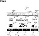
- Fig. 3 shows an image 110 to be displayed on the screen of the liquid crystal display 101.
- the liquid crystal display 101 displays, for example, texts 110a indicating the name of the place where the apparatus is located, the time, the set temperature, the mode, the wind speed, and/or the like, icons 110b indicating the setting of the mode of the apparatus and the wind speed, buttons 110c for changing the mode, the set temperature and the wind speed, and a figure image 110d such as a line for improving the visibility of the screen.
- the touch panel 101a detects the touched position, and outputs the detection result.
- the circuit board 102 is a rectangular board on which an arithmetic operation circuit 102a, a memory circuit 102b, and an input/output circuit 102c are formed, and further has a connector 102d and a communication terminal 102e mounted thereon.
- the circuits 102a to 102c, the connector 102d, the communication terminal 102e and the Liquid crystal display 101 are connected to one another by a system bus 103.
- the arithmetic operation circuit 102a has a CPU and a volatile memory, such as RAM, which serves as a work area for this CPU.
- the program stored in the memory circuit 102b is loaded and executed by the arithmetic operation circuit 102a.
- the memory circuit 102b has a semiconductor memory, such as EPROM and/or the like, and stores a program for controlling the liquid crystal display 101, a program for processing information output from the touch panel 101a, images to be displayed on the liquid crystal display 101, information relating to image parts (attribute data, database) constituting the images, and/or the like.
- a semiconductor memory such as EPROM and/or the like
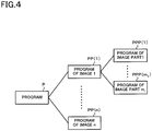
- Fig. 4 is a diagram showing the structure of a program P stored in the memory circuit 102b.
- This program P is comprised of programs PP(1) to PP(n) relating to images 1 to n.
- the program PP(1) is comprised of programs PPP(1) to PPP(m 1 ) which are executed when image parts 1 to m 1 constituting the image 1 are displayed on the liquid crystal display 101, or are manipulated via the touch panel 101a.
- each program of programs PP(i) (i ranging from 2 to n), though not illustrated, is comprised of programs PPP(1) to PPP(m i ) relating to image parts 1 to m i constituting the image i.
- Each of the image parts 1 to m 1 is a part for constructing an image displayed on the screen, such as the text 110a, icon 110b, button 110c, or figure image 110d shown in Fig. 3 .
- Each of the image parts 1 to m 1 has attribute data defining the contents of a program which is executed when each of the image parts 1 to m 1 is manipulated via the touch panel 101a.
- the attribute data includes the name of an image part, information for defining to which one of the images 1 to n the image part belongs, positional information when the image part is displayed on the liquid crystal display 101, information for defining whether the image part is a part to be manipulated like the button 110c, or an image which is used only in display of information like the text 110a, and color information of the image part.
- This attribute data is created by the image construction apparatus 10, and is uploaded to the memory circuit 102b of the remote control apparatus 100 via the in-circuit emulator 20.
- Fig. 5 is a diagram specifically illustrating the relation among the program PP(110) relating to the image 110 shown in Fig. 3 , programs PPP(110a 1 ) to PPP(110a 6 ) which are respectively assigned to texts 110a 1 to 110a 6 which constitute this image, a program PPP(110b 1 ) and a program PPP(110b 2 ) which are respectively assigned to an icons 110b 1 and 110b 2 , and programs PPP(110c 1 ) to PPP(110c 4 ) which are respectively assigned to buttons 110c 1 to 110c 4 .
- programs PPP(110a 1 ) to PPP(110a 6 ) which are respectively assigned to texts 110a 1 to 110a 6 which constitute this image
- a program PPP(110b 1 ) and a program PPP(110b 2 ) which are respectively assigned to an icons 110b 1 and 110b 2
- programs PPP(110c 1 ) to PPP(110c 4 ) which are respectively assigned to buttons 110c 1 to 110c 4
- the program PP(110) relating to the image 110 is comprised of the programs PPP(110a 1 ) to PPP(110a 6 ), the program PPP(110b 1 ), the program PPP(110b 2 ), and the programs PPP(110c 1 ) to PPP(110c 4 ).
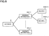
- Fig. 6 is a diagram showing the structure of a database stored in the memory circuit 102b.
- This database has a hierarchical structure including records and property information having a set of records.
- Property information relates to an air conditioning system network which is created by a plurality of air conditioning systems 1 to n. Specifically, the property information relates to the operational conditions of each of the air conditioning systems creating the air conditioning system network, the room temperature which is the control target of each air conditioning system, and the temperature, the amount of wind, the direction of wind, and/or the like, set in each air conditioning system.
- a record is information relating to a single air conditioning system constituting the air conditioning system network.
- This information like the property information, relates to the operational conditions of the air conditioning system, the room temperature detected by the air conditioning system, and the temperature, the amount of wind, the direction of wind, and/or the like, set in the air conditioning system.
- the remote control apparatus 100 acquires data held in each air conditioning system in a given cycle, and updates the records successively. Accordingly, the contents of the records creating the database in the remote control apparatus 100 are updated in synchronism with the update of the data held in the individual air conditioning systems.
- a set of records DDD(1) to DDD(r 1 ) of the individual air conditioning systems create property information DD(1) of the air conditioning system network.
- the contents of the property information DD(1) are updated as needed.
- Property information DD(i) is likewise comprised of records DDD(1) to DDD(r i ) (i ranging from 2 to n), and as the individual records DDD(1) to DDD(r i ) are successively updated, the contents of the property information DD(i) are updated as needed.
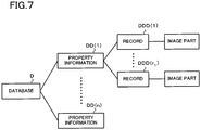
- Fig. 7 is a diagram showing the relation between the records DDD(1) to DDD(r 1 ) constituting the database stored in the memory circuit 102b of the remote control apparatus 100 and the image parts.
- the aforementioned image part is associated with each information constituting each of the records DDD(1) to DDD(r 1 ).
- the text 110a 1 constituting the image 110 shown in Fig. 3 is associated with the information relating to the set location of the record DDD.
- the text 110a 3 and the icon 110b 1 are associated with information on the mode.
- Information relating to the text 110a 6 is associated with information on the set temperature.
- the text 110a 5 and the icon 110b 2 are associated with information on the wind speed.
- the program assigned to the image part is associated with the record DDD.
- the program of the text 110a 1 is associated with a set-location record DDD(a).
- each of the program of the text 110a 3 and the program of the icon 110b 1 is associated with the a mode record DDD(b).
- the program of the text 110a 6 is associated with a set-temperature record DDD(c).
- each of the program of the text 110a 5 and the program of the icon 110b 2 is associated with the a wind-speed record DDD(d).
- the circuit that is comprised of the aforementioned arithmetic operation circuit 102a, memory circuit 102b and input/output circuit 102c is connected via the communication terminal 102e to the air conditioning system to be operated.
- the CPU 10a reads the image creating program from the auxiliary memory unit 10c, and executes the program. As a result, an image construction window W1 shown in Fig. 9 is displayed on the display unit 10d.
- the image construction window W1 shown in Fig. 9 is comprised of a tool bar 51, a work area 52, a tree figure display area 53, and a property display area 54.
- the user can create a desired image displayed by the remote control apparatus 100 by arranging the image parts, such as the texts 110a 1 to 110a 6 , the icons 110b 1 , 110b 2 , and the buttons 110c 1 to 110c 4 shown in Fig. 3 , in the work area 52.
- the names of the image parts arranged in the work area 52 are displayed in the tree figure display area 53. This tree figure shows the relation between an image and image parts.
- the attribute data of the selected image part can be written in the property display area 54.
- the user sequentially selects an image part to write its attribute data, and executes processes assigned to the icons and tags which constitute the tool bar 51.
- the source code of a program for executing the process defined by the attribute data of the image part constituting the image is generated.
- this source code is compiled to generate a binary-coded program.
- the user can generate a program which is assigned to the each image part by sequentially selecting a desired part image and executing the aforementioned procedures.
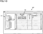
- Fig. 10 is a diagram showing a database creation window W2.
- the database creation window W2 is comprised of a database display area 61 and a database editing area 62.
- the user displays the database creation window W2 on the display unit 10d, and selects a record item in the database shown in the database display area 61.
- the contents of records DDD(1) to DDD(r j ) constituting property information DD(j) (j ranging from 1 to n) can be entered in the database editing area 62.
- the user can create a desired database D by entering the contents of the records DDD(1) to DDD(r j ) in the database editing area 62.
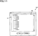
- Fig. 11 is a diagram showing an execution window W3 for associating an image part with a database.
- the execution window W3 is an input screen for executing association of records DDD constituting the database D shown in Fig. 7 or Fig. 8 with image parts.
- the user can associate a record DDD with an image part by displaying the image construction window W1 on the display unit 10d, selecting the desired image part, then displaying the exection window W3, and selecting the desired record DDD.
- the user can upload the database D and the binary-coded program P and/or the like which are associated with each other into the memory circuit 102b of the remote control apparatus 100 via the in-circuit emulator 20.
- Fig. 12 is a diagram showing data uploaded into the memory circuit 102b.
- uploaded data 1101 defining the arrangement of an image part
- uploaded data 1102 defining the association of the image part with a database
- uploaded data 1103 about the database are stored in the memory circuit 102b.
- the remote control apparatus 100 When the remote control apparatus 100 is activated, those data are read out into the CPU of the arithmetic operation circuit 102a as needed, and stored in the RAM and/or the like provided as the work area of the arithmetic operation circuit 102a.
- the image construction apparatus 10 has a function of creating a binary-coded program, a function of creating a database, and a function of associating a database with an image part, in accordance with an instruction from the user. Using those functions, the user can easily construct an image comprised of image parts associated with both the program and the database.
- the user has functionality and diversity of a personalized source-coded program without writing/coding/creating a source-coded program, which is conventionally written by a programmer. Therefore, a user who is not experienced with programming can easily construct an image to be displayed on the liquid crystal display 101 of the remote control apparatus 100.
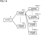
- a program PP(1) assigned to an image 1 includes programs PPPa(1) to PPPa(m 1 ) assigned to image parts 1 to m 1 , and programs PPPb(1) to PPPb(k 1 ) directly assigned to the image 1.
- each program of programs PP(i) i ranging from 2 to n
- each program of programs PP(i) likewise includes programs PPPa(1) to PPPa(m i ) assigned to image parts 1 to m i constituting an image i, and programs PPPb(1) to PPPb(k i ) directly assigned to the image i.
- the image construction apparatus 10 according to this embodiment differs from the image construction apparatus 10 according to the first embodiment in those points.
- Programs PPPa(1) to PPPa(m j ) are programs which are each executed when displayed on the liquid crystal display 101 or when operated via the touch panel 101a. When an image part is manipulated, for example, this program highlights or flickers the color of the image part.
- Programs PPPb(1) to PPPb(k j ) are programs which, upon manipulation of an image part such as a button, for example, changes the contents of the text of another image part. When an arrow for raising the set temperature is manipulated, for example, those programs PPPb(1) to PPPb(k j ) change the contents of the text corresponding to the set temperature, for example, from 25°C to 26°C.
- An image movement setting window W4 shown in Fig. 14 is comprised of a movement setting area 71, a sequence changing button 72 and a pull-down menu 73.
- the image movement setting window W4 is displayed on the display unit 10d.
- the user can input the content of a movement into the movement setting area 71 of the image movement setting window W4.
- the input of the movement content can also be made by the user's selecting a desired movement from a plurality of movements listed in a menu appearing by opening the pull-down menu 73 in addition to the user's direct input.
- the user can change the sequence of selected movements by activating the sequence changing button 72.
- the image part is assigned with the program (PPPb) and/or the like to change the contents of the text of another image part.
- the image construction apparatus 10 has a function of creating a program to change the content of another image part and assigning this program to a prescribed image part. Using this function, the user can easily create a program to change the content of another image part and assign this program to a prescribed image part.
- the user has functionality and diversity of a personalized source-coded program without writing/coding/creating a source-coded program, which is conventionally written by a programmer. Therefore, a user who is not experienced with programming can create a program to change the content of another image part and assign this program to a prescribed image part.
- the image construction apparatus 10 according to the third embodiment of the invention differs from the image construction apparatus 10 according to each of the foregoing embodiments in its capability of setting transition of an image.
- Fig. 15 is a diagram conceptually illustrating an image transition showing that an image 2 is displayed on the liquid crystal display 101 when an image part constituting an image 1 displayed on the liquid crystal display 101 of the remote control apparatus 100 is manipulated.
- a plurality of screens are shown in a display area 80 of a transition setting window W5 shown in Fig. 16 .
- transition setting window W5 transition of an image is represented by an arrow having an image part constituting one image as a start point and another image as the end point.
- a transition indicating arrow 83 shows that when an image part 81a constituting an image 81 displayed on the liquid crystal display 101 is manipulated, the image displayed on the liquid crystal display 101 is changed to an image 82.
- the user can create a program to define the transition of an image by placing the transition indicating arrow 83 on the transition setting window W5 in such a way that an image part constituting an image at the transition origin becomes the start point and an image at the transition destination becomes an end point.
- an image part constituting the image at the transition origin is selected with a pointing device and/or the like , and then the image at the transition destination is selected therewith.
- a command defined by an icon on the tool bar is executed under this situation to enable the placement of the transition indicating arrow 83.
- the user can change an image at the transition destination by selecting the transition indicating arrow 83 already placed, and then selecting an image at the transition destination.
- the image construction apparatus 10 has a function of creating a program to define the transition of an image. Using this function, the user can easily create a program to define the transition of an image.
- the image construction apparatus 10 shows the transition of an image with the transition indicating arrow 83.
- a user may visually confirm an image at the transition origin and an image at the transition destination.
- Fig. 17 shows the liquid crystal display 101 constituting the remote control apparatus 100 according to the fourth embodiment, the touch panel 101a attached to cover the liquid crystal display 101, and the circuit board 102 accommodated in the remote control apparatus 100.
- the remote control apparatus 100 differs from each of the foregoing embodiments in that an external button 101b is provided on a board 104 on which the liquid crystal display 101 is mounted, and a contact 102f, which operates when the external button 101b is operated, is mounted on the circuit board 102.
- the contact 102f is, for example, a normally open contact which is connected to the arithmetic operation circuit 102a via a conductor pattern provided on the circuit board 102.
- the arithmetic operation circuit 102a can detect the user's operation of the external button 101b via the contact 102f.
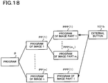
- Fig. 18 is a diagram showing programs PPP constituting a program P and assigned to image parts, and the external button 101b associated with the programs PPP.
- Fig. 18 shows that when the external button 101b is operated, a program PPP(1) constituting a program PP(1) of an image 1 and assigned to an image part 1, and a program PPP(1) constituting a program PP(n) of an image n and assigned to the image part 1 are executed.
- a process equivalent to the one performed when operated via the touch panel 101a is performed on the image part 1 of the image 1 and the image part 1 of the image n.
- Fig. 19A is a diagram showing an external key setting window W6.
- Fig. 19B is a diagram showing a control setting window W7.
- the user can assign the desired process to the external button selected on the external key setting window W6.
- the entry of the process content into the control setting window W7 can be made by selecting a desired process from a plurality of processes listed in a menu appearing by opening a pull-down menu 91.
- the user can change the sequence of selected processes by activating a sequence changing button 92.
- a program assigned to an image part can be assigned to the external button 101b.
- the image construction apparatus 10 has a function of assigning a program to an external button provided on the remote control apparatus 100. Using this function, the user can easily assign a program assigned to another image part to the external button too.
- the user has functionality and diversity of a personalized source-coded program without writing/coding/creating a source-coded program, which is conventionally written by a programmer. Therefore, a user who is not experienced with programming can easily assign a program assigned to another image part to the external button too.
- the remote control apparatus 100 has both the touch panel 101a and the external button 101b. Depending on the functions of the remote control apparatus 100, however, the touch panel 101a is optional.
- the programs stored in the auxiliary memory unit 10c of the image construction apparatus 10 in each of the above-described embodiments may be stored in a computer readable recording medium, such as a flexible disk, CD-ROM (Compact Disk Read-Only Memory), DVD (Digital Versatile Disk) or MO (Magneto-Optical disk), for its distribution, and may be installed to configure an apparatus which executes the above-described processes.
- a computer readable recording medium such as a flexible disk, CD-ROM (Compact Disk Read-Only Memory), DVD (Digital Versatile Disk) or MO (Magneto-Optical disk)
- the programs may be stored in a disk drive unit and/or the like of a predetermined server apparatus on a communication network, such as the Internet, and may be downloaded in the form of a carrier having the programs superimposed thereon.
- the image construction apparatus and program of the present invention are suitable for constructing the screen of a remote control apparatus having a graphical user interface.
Landscapes
- Engineering & Computer Science (AREA)
- Software Systems (AREA)
- General Engineering & Computer Science (AREA)
- Theoretical Computer Science (AREA)
- Physics & Mathematics (AREA)
- Human Computer Interaction (AREA)
- General Physics & Mathematics (AREA)
- Combustion & Propulsion (AREA)
- Mechanical Engineering (AREA)
- Chemical & Material Sciences (AREA)
- Computer Networks & Wireless Communication (AREA)
- Selective Calling Equipment (AREA)
- Stored Programmes (AREA)
- User Interface Of Digital Computer (AREA)
Claims (6)
- Bildaufbauvorrichtung (10) zum Aufbauen eines Bildes (110), das auf einem Bildschirm (101) einer Fernsteuervorrichtung (100), die eine Vielzahl von ein Netzwerk aufbauenden Geräten betreibt, angezeigt werden soll, dadurch gekennzeichnet, dass sie umfasst:ein Bilderzeugungsmittel (10a), das das Bild (110), das einen Bildteil (110a, 110b, 110c, 110d) enthält, der Informationen (DD) über die Geräte angibt, erzeugt;ein Datenbankerzeugungsmittel (10a), das eine Datenbank (D) erzeugt, die auf den Informationen (DD) über die Geräte, die über das Netzwerk akquiriert werden, basiert;ein Verknüpfungsmittel (10a), das die Gerätinformationen (DD), die die Datenbank (D) bilden, mit dem Bildteil (110a, 110b, 110c, 110d) entsprechend den Gerätinformationen (DD) verknüpft;ein Quellcodeerzeugungsmittel (10a), das einen Quellcode eines Programms (P) zum Definieren eines Wechsels des Bildes und zum Ausführen eines Prozesses, der dem Bildteil (110a, 110b, 110c, 110d), mit dem die Gerätinformationen (DD) verknüpft sind, zugeordnet ist, erzeugt;ein Programmerzeugungsmittel (10a), das den Quellcode kompiliert, um ein binär kodiertes Programm (P) zu erzeugen; undein Schreibmittel (10a), das das Programm (P) in ein Speichermittel (102b), das in der Fernsteuervorrichtung (100) enthalten ist, schreibt; undein Anzeigemittel, das, wenn ein Bild (110), das auf dem Bildschirm (101) der Fernsteuervorrichtung (100) angezeigt wird, durch Ausführen des Programms (P), das den Prozess ausführt, der dem Bildteil (110a, 110b, 110c, 110d) zugeordnet ist, gewechselt wird, das Bild (110) anzeigt, das den Bildteil an einem Wechselursprung und das Bild (110) an einem Wechselziel enthält,wobei das Anzeigemittel (10d) eine Übergangslinie (83) anzeigt, die den Bildteil (110a, 110b, 110c, 110d) und das Bild (110a, 110b, 110c, 110d) des Wechselziels verbindet.
- Bildaufbauvorrichtung (10) nach Anspruch 1, dadurch gekennzeichnet, dass die Fernsteuervorrichtung (100) eine grafische Benutzerschnittstelle (101, 101a) enthält, die aufweist:einen Bildschirm (101), der das Bild (110) anzeigt; undein Berührungsfeld (101a), das den Bildschirm (101) überlagernd angeordnet ist.
- Bildaufbauvorrichtung (10) nach Anspruch 2, dadurch gekennzeichnet, dass das Programm (P) ausgeführt wird, wenn Positionsinformationen des Bildteils (110a, 110b, 110c, 110d), dem ein Inhalt des Prozesses zugeordnet ist, zu Positionsinformationen passen, die vom Berührungsfeld (101a) ausgegeben werden.
- Bildaufbauvorrichtung (10) nach Anspruch 1, dadurch gekennzeichnet, dass die Fernsteuervorrichtung (100) enthält:eine Schnittstelle, die einen Betriebsschalter (101b) aufweist;ein Zuordnungsmittel (10a), das einen gleichen Prozess, wie den Prozess, der dem Bildteil (110a, 110b, 110c, 110d) zugeordnet ist, dem Betriebsschalter (101b) zuordnet;ein Quellcodeerzeugungsmittel (10a), das einen Quellcode eines Programms (P), das einen Prozess ausführt, wenn der Betriebsschalter (101b) betätigt wird, erzeugt.
- Bildaufbauvorrichtung (10) nach Anspruch 1, dadurch gekennzeichnet, dass die Geräte Klimaanlagen sind.
- Programm, das einen Steuercomputer für eine Bildaufbauvorrichtung (10) zum Aufbauen einer Bild-(110)-Anzeige durch eine Fernsteuervorrichtung (100), gekennzeichnet durch Betätigen einer Vielzahl von Geräten, die ein Netzwerk aufbauen, erzielen lässt:Erzeugen des Bildes (110), das einen Bildteil (110a, 110b, 110c, 110d) enthält, der Informationen (DD) über die Geräte angibt;Erzeugen einer Datenbank (D), die auf den Informationen (DD) über die Geräte basiert, die über das Netzwerk akquiriert wurden;Verknüpfen der Gerätinformationen (DD), die die Datenbank (D) bilden, mit dem Bildteil (110a, 110b, 110d, 110d) der den Gerätinformationen entspricht;Erzeugen eines Quellcodes eines Programms (P) zum Definieren eines Wechsels des Bildes und zum Ausführen eines Prozesses, der dem Bildteil (110a, 110b, 110c, 110d) zugeordnet ist, mit dem die Gerätinformationen (DD) verknüpft sind;Kompilieren des Quellcodes, um ein binär kodiertes Programm (P) zu erzeugen; undSchreiben des Programms (P) in Speichermittel (102b), die in der Fernsteuervorrichtung (100) vorgesehen sind; undAnzeigen, wenn ein Bild, das auf einem Bildschirm (101) der Fernsteuervorrichtung (100) angezeigt wird, gewechselt wird durch Ausführen des Programms (P), das den dem Bildteil (110a, 110b, 110c, 110d) zugeordneten Prozess ausführt, des Bilds (110), das den Bildteil an einem Wechselursprung und das Bild an einem Wechselziel enthält,wobei eine Übergangslinie (83), die den Bildteil (110a, 110b, 110b, 110d) und das Bild (110a, 110b, 110c, 110d) des Wechselziels verbindet, angezeigt wird.
Applications Claiming Priority (2)
| Application Number | Priority Date | Filing Date | Title |
|---|---|---|---|
| JP2009214374 | 2009-09-16 | ||
| PCT/JP2010/056247 WO2011033803A1 (ja) | 2009-09-16 | 2010-04-06 | 画像構築装置及びプログラム |
Publications (3)
| Publication Number | Publication Date |
|---|---|
| EP2472902A1 EP2472902A1 (de) | 2012-07-04 |
| EP2472902A4 EP2472902A4 (de) | 2013-01-23 |
| EP2472902B1 true EP2472902B1 (de) | 2017-08-30 |
Family
ID=43758416
Family Applications (1)
| Application Number | Title | Priority Date | Filing Date |
|---|---|---|---|
| EP10816916.0A Not-in-force EP2472902B1 (de) | 2009-09-16 | 2010-04-06 | Bilderzeugungsvorrichtung und -programm |
Country Status (7)
| Country | Link |
|---|---|
| US (1) | US8339416B2 (de) |
| EP (1) | EP2472902B1 (de) |
| JP (1) | JP4724261B2 (de) |
| CN (1) | CN102498724B (de) |
| ES (1) | ES2642082T3 (de) |
| TW (1) | TWI432924B (de) |
| WO (1) | WO2011033803A1 (de) |
Families Citing this family (15)
| Publication number | Priority date | Publication date | Assignee | Title |
|---|---|---|---|---|
| US8878854B2 (en) * | 2011-12-13 | 2014-11-04 | Lennox Industries Inc. | Heating, ventilation and air conditioning system user interface having adjustable fonts and method of operation thereof |
| EP2821864B1 (de) * | 2013-07-03 | 2015-10-21 | Kverneland Group Mechatronics BV | Benutzerschnittstellentafel für Landwirtschaftsmaschine |
| FR3009392B1 (fr) * | 2013-08-05 | 2015-08-21 | Elettroniche Ind Automatismi S P A C E I A S P A Costruzioni | Syteme pour la configuration d'un detecteur portatif |
| EP3234764B1 (de) * | 2014-12-15 | 2019-10-02 | Intel Corporation | Instrumentation von grafischen befehle |
| CN105183492B (zh) * | 2015-10-30 | 2018-04-06 | 上海斐讯数据通信技术有限公司 | 个性化对话框的形成方法及形成装置 |
| JP2018094689A (ja) * | 2016-12-15 | 2018-06-21 | 中村留精密工業株式会社 | 工作機械 |
| USD881202S1 (en) * | 2017-05-08 | 2020-04-14 | Kci Licensing, Inc. | Display screen with graphical user interface for negative pressure unit |
| JP2019096123A (ja) * | 2017-11-24 | 2019-06-20 | 日本精機株式会社 | 組込みソフトウェアの作成方法 |
| CN112424539A (zh) * | 2018-02-01 | 2021-02-26 | 安定宝公司 | 用于hvac系统的带有可编程快捷按钮的无线控制器 |
| JP2020027535A (ja) * | 2018-08-16 | 2020-02-20 | 如如研創股▲分▼有限公司 | 設計仕様書に基づいたbomの作成方法 |
| JP2020027597A (ja) * | 2018-12-21 | 2020-02-20 | 如如研創股▲分▼有限公司 | ソフトウェアシステム作成システム |
| JP2020027663A (ja) * | 2019-09-16 | 2020-02-20 | 如如研創股▲分▼有限公司 | 仕様書作成部 |
| JP7354768B2 (ja) * | 2019-10-30 | 2023-10-03 | 日本精機株式会社 | 遠隔操作装置 |
| JP7621758B2 (ja) | 2019-11-19 | 2025-01-27 | キヤノン電子株式会社 | アプリケーション作成画面の表示制御方法、プログラムおよび情報処理装置 |
| JP7467103B2 (ja) * | 2019-11-19 | 2024-04-15 | キヤノン電子株式会社 | アプリケーション作成画面の表示制御方法、プログラムおよび情報処理装置 |
Family Cites Families (17)
| Publication number | Priority date | Publication date | Assignee | Title |
|---|---|---|---|---|
| US6211870B1 (en) * | 1997-07-07 | 2001-04-03 | Combi/Mote Corp. | Computer programmable remote control |
| US5819294A (en) * | 1997-08-06 | 1998-10-06 | Philips Electronics North America Corporation | Automatic configuration mechanism for universal remote |
| WO1999016282A1 (en) | 1997-09-25 | 1999-04-01 | Mitsubishi Denki Kabushiki Kaisha | Remote control device |
| EP0913750B1 (de) * | 1997-10-31 | 2003-02-12 | Endress + Hauser GmbH + Co. KG | Anordnung zum Fernsteuern und/oder Fernbedienen eines Feldgeräts mittels eines Steuergeräts über einen Feldbus |
| US6127941A (en) * | 1998-02-03 | 2000-10-03 | Sony Corporation | Remote control device with a graphical user interface |
| KR100772344B1 (ko) * | 1998-12-28 | 2007-11-01 | 코닌클리케 필립스 일렉트로닉스 엔.브이. | 완전 기능성 원격 제어 편집기 및 에뮬레이터 |
| US6937972B1 (en) | 1999-03-17 | 2005-08-30 | Koninklijke Philips Electronics N.V. | Fully functional remote control editor and emulator |
| JP2002024020A (ja) * | 2000-05-01 | 2002-01-25 | Toshiba Corp | 画面制御プログラム、動的表示情報取得プログラム、画面表示トランザクションプログラム、画面コンポーネントインタフェースプログラム、画面プログラム作成方法 |
| JP4358414B2 (ja) * | 2000-08-10 | 2009-11-04 | 株式会社エクサ | アプリケーション構築方法及び実行方法並びにアプリケーション構築装置及びアプリケーション実行システム並びにアプリケーション構築方法を記録した記録媒体及びアプリケーション実行方法を記録した記録媒体 |
| US8264489B2 (en) * | 2003-07-11 | 2012-09-11 | Intel Corporation | Interface remoting |
| US7788657B2 (en) * | 2004-02-27 | 2010-08-31 | Tvworks, Llc | Targeted runtime compilation |
| JP5032842B2 (ja) * | 2004-03-26 | 2012-09-26 | パナソニック株式会社 | 表示処理装置及び表示処理方法 |
| US20060052884A1 (en) * | 2004-09-08 | 2006-03-09 | Staples Mathew L | User interface builder application for building automation |
| JP2007140983A (ja) * | 2005-11-18 | 2007-06-07 | Canon Inc | リモート操作端末装置 |
| JP2009517949A (ja) * | 2005-11-30 | 2009-04-30 | コーニンクレッカ フィリップス エレクトロニクス エヌ ヴィ | 汎用リモコン装置の設定 |
| JP4924402B2 (ja) * | 2007-12-14 | 2012-04-25 | ブラザー工業株式会社 | 制御装置および制御プログラム |
| US9350850B2 (en) * | 2008-04-18 | 2016-05-24 | Uei Cayman Inc. | Using HDMI-CEC to identify a codeset |
-
2010
- 2010-04-06 EP EP10816916.0A patent/EP2472902B1/de not_active Not-in-force
- 2010-04-06 US US13/395,792 patent/US8339416B2/en not_active Expired - Fee Related
- 2010-04-06 ES ES10816916.0T patent/ES2642082T3/es active Active
- 2010-04-06 JP JP2011505295A patent/JP4724261B2/ja not_active Expired - Fee Related
- 2010-04-06 WO PCT/JP2010/056247 patent/WO2011033803A1/ja not_active Ceased
- 2010-04-06 CN CN201080041258.6A patent/CN102498724B/zh not_active Expired - Fee Related
- 2010-09-15 TW TW099131157A patent/TWI432924B/zh not_active IP Right Cessation
Non-Patent Citations (1)
| Title |
|---|
| None * |
Also Published As
| Publication number | Publication date |
|---|---|
| JPWO2011033803A1 (ja) | 2013-02-07 |
| TWI432924B (zh) | 2014-04-01 |
| US8339416B2 (en) | 2012-12-25 |
| EP2472902A4 (de) | 2013-01-23 |
| WO2011033803A1 (ja) | 2011-03-24 |
| CN102498724B (zh) | 2016-02-17 |
| JP4724261B2 (ja) | 2011-07-13 |
| EP2472902A1 (de) | 2012-07-04 |
| CN102498724A (zh) | 2012-06-13 |
| US20120176405A1 (en) | 2012-07-12 |
| ES2642082T3 (es) | 2017-11-15 |
| TW201120591A (en) | 2011-06-16 |
Similar Documents
| Publication | Publication Date | Title |
|---|---|---|
| EP2472902B1 (de) | Bilderzeugungsvorrichtung und -programm | |
| US20060052884A1 (en) | User interface builder application for building automation | |
| EP1736854A2 (de) | Verfahren und System zur dynamischen Darstellung einer Komponentenkonfiguration | |
| JP2014533403A (ja) | キーボードにマップされたキーボード・ショートカットを提供すること | |
| US9651926B2 (en) | System, method, work station and computer program product for controlling an industrial process | |
| JP4554570B2 (ja) | プログラマブル表示器、制御プログラムおよびそれを記録した記録媒体、ならびに制御システム、クライアントプログラムおよびそれを記録した記録媒体 | |
| CN119343643A (zh) | 梯形图程序编辑装置、编辑方法及编辑程序 | |
| US20060277026A1 (en) | Universal web-based reprogramming method and system | |
| JPH09120352A (ja) | マルチウィンドウシステム | |
| JP4463716B2 (ja) | プログラマブル表示器、表示制御プログラムおよびそれを記録した記録媒体 | |
| EP3798821B1 (de) | Designassistenzvorrichtung für gui-steuergerät, fernsteuerungssystem und programm | |
| WO2007106085A1 (en) | Configurable human-machine interface configuration method and system using a remote interface | |
| JP2010170497A (ja) | 画像作成装置、画像作成プログラムおよびそれを記録した記録媒体 | |
| JP2008293392A (ja) | ラダープログラミングエディタ | |
| US20040150626A1 (en) | Operator interface panel with control for visibility of desplayed objects | |
| JP2012079132A (ja) | ラダープログラム作成支援装置、そのプログラム | |
| JP2015018422A (ja) | 制御システム及びそのエンジニアリングに用いるプログラム | |
| JP2009104434A (ja) | モニタ画面上へのラダー図表示方式 | |
| JP2011248623A (ja) | 監視制御システム | |
| JP7215054B2 (ja) | プログラミング表示装置、プログラミング表示方法、およびプログラム | |
| Wu et al. | Interactive Touchscreen Directory | |
| Koomsap | Exploring the Adoption of UX-Driven Approaches to Design Industrial PLC User | |
| JPH0317741A (ja) | プログラム作成支援装置 | |
| JP2005251014A (ja) | 制御システム、制御モニタプログラムおよびそのプログラムを記録した記録媒体、ならびにエディタ装置、エディタプログラムおよびそのプログラムを記録した記録媒体 | |
| JPH02263227A (ja) | 表示制御装置 |
Legal Events
| Date | Code | Title | Description |
|---|---|---|---|
| PUAI | Public reference made under article 153(3) epc to a published international application that has entered the european phase |
Free format text: ORIGINAL CODE: 0009012 |
|
| 17P | Request for examination filed |
Effective date: 20120316 |
|
| AK | Designated contracting states |
Kind code of ref document: A1 Designated state(s): AT BE BG CH CY CZ DE DK EE ES FI FR GB GR HR HU IE IS IT LI LT LU LV MC MK MT NL NO PL PT RO SE SI SK SM TR |
|
| DAX | Request for extension of the european patent (deleted) | ||
| A4 | Supplementary search report drawn up and despatched |
Effective date: 20130103 |
|
| RIC1 | Information provided on ipc code assigned before grant |
Ipc: H04Q 9/00 20060101AFI20121219BHEP Ipc: F24F 11/00 20060101ALI20121219BHEP Ipc: G06F 9/44 20060101ALI20121219BHEP |
|
| 17Q | First examination report despatched |
Effective date: 20140414 |
|
| GRAP | Despatch of communication of intention to grant a patent |
Free format text: ORIGINAL CODE: EPIDOSNIGR1 |
|
| RIC1 | Information provided on ipc code assigned before grant |
Ipc: F24F 11/00 20060101ALI20170221BHEP Ipc: H04Q 9/00 20060101AFI20170221BHEP Ipc: G08C 17/00 20060101ALI20170221BHEP Ipc: G06F 9/44 20060101ALI20170221BHEP |
|
| INTG | Intention to grant announced |
Effective date: 20170320 |
|
| GRAS | Grant fee paid |
Free format text: ORIGINAL CODE: EPIDOSNIGR3 |
|
| GRAA | (expected) grant |
Free format text: ORIGINAL CODE: 0009210 |
|
| AK | Designated contracting states |
Kind code of ref document: B1 Designated state(s): AT BE BG CH CY CZ DE DK EE ES FI FR GB GR HR HU IE IS IT LI LT LU LV MC MK MT NL NO PL PT RO SE SI SK SM TR |
|
| REG | Reference to a national code |
Ref country code: GB Ref legal event code: FG4D |
|
| REG | Reference to a national code |
Ref country code: CH Ref legal event code: EP |
|
| REG | Reference to a national code |
Ref country code: AT Ref legal event code: REF Ref document number: 924684 Country of ref document: AT Kind code of ref document: T Effective date: 20170915 |
|
| REG | Reference to a national code |
Ref country code: IE Ref legal event code: FG4D |
|
| REG | Reference to a national code |
Ref country code: DE Ref legal event code: R096 Ref document number: 602010044894 Country of ref document: DE |
|
| REG | Reference to a national code |
Ref country code: ES Ref legal event code: FG2A Ref document number: 2642082 Country of ref document: ES Kind code of ref document: T3 Effective date: 20171115 |
|
| REG | Reference to a national code |
Ref country code: NL Ref legal event code: MP Effective date: 20170830 |
|
| REG | Reference to a national code |
Ref country code: LT Ref legal event code: MG4D |
|
| REG | Reference to a national code |
Ref country code: AT Ref legal event code: MK05 Ref document number: 924684 Country of ref document: AT Kind code of ref document: T Effective date: 20170830 |
|
| PG25 | Lapsed in a contracting state [announced via postgrant information from national office to epo] |
Ref country code: LT Free format text: LAPSE BECAUSE OF FAILURE TO SUBMIT A TRANSLATION OF THE DESCRIPTION OR TO PAY THE FEE WITHIN THE PRESCRIBED TIME-LIMIT Effective date: 20170830 Ref country code: SE Free format text: LAPSE BECAUSE OF FAILURE TO SUBMIT A TRANSLATION OF THE DESCRIPTION OR TO PAY THE FEE WITHIN THE PRESCRIBED TIME-LIMIT Effective date: 20170830 Ref country code: FI Free format text: LAPSE BECAUSE OF FAILURE TO SUBMIT A TRANSLATION OF THE DESCRIPTION OR TO PAY THE FEE WITHIN THE PRESCRIBED TIME-LIMIT Effective date: 20170830 Ref country code: AT Free format text: LAPSE BECAUSE OF FAILURE TO SUBMIT A TRANSLATION OF THE DESCRIPTION OR TO PAY THE FEE WITHIN THE PRESCRIBED TIME-LIMIT Effective date: 20170830 Ref country code: HR Free format text: LAPSE BECAUSE OF FAILURE TO SUBMIT A TRANSLATION OF THE DESCRIPTION OR TO PAY THE FEE WITHIN THE PRESCRIBED TIME-LIMIT Effective date: 20170830 Ref country code: NO Free format text: LAPSE BECAUSE OF FAILURE TO SUBMIT A TRANSLATION OF THE DESCRIPTION OR TO PAY THE FEE WITHIN THE PRESCRIBED TIME-LIMIT Effective date: 20171130 |
|
| PG25 | Lapsed in a contracting state [announced via postgrant information from national office to epo] |
Ref country code: GR Free format text: LAPSE BECAUSE OF FAILURE TO SUBMIT A TRANSLATION OF THE DESCRIPTION OR TO PAY THE FEE WITHIN THE PRESCRIBED TIME-LIMIT Effective date: 20171201 Ref country code: LV Free format text: LAPSE BECAUSE OF FAILURE TO SUBMIT A TRANSLATION OF THE DESCRIPTION OR TO PAY THE FEE WITHIN THE PRESCRIBED TIME-LIMIT Effective date: 20170830 Ref country code: IS Free format text: LAPSE BECAUSE OF FAILURE TO SUBMIT A TRANSLATION OF THE DESCRIPTION OR TO PAY THE FEE WITHIN THE PRESCRIBED TIME-LIMIT Effective date: 20171230 Ref country code: BG Free format text: LAPSE BECAUSE OF FAILURE TO SUBMIT A TRANSLATION OF THE DESCRIPTION OR TO PAY THE FEE WITHIN THE PRESCRIBED TIME-LIMIT Effective date: 20171130 |
|
| REG | Reference to a national code |
Ref country code: FR Ref legal event code: PLFP Year of fee payment: 9 |
|
| PG25 | Lapsed in a contracting state [announced via postgrant information from national office to epo] |
Ref country code: NL Free format text: LAPSE BECAUSE OF FAILURE TO SUBMIT A TRANSLATION OF THE DESCRIPTION OR TO PAY THE FEE WITHIN THE PRESCRIBED TIME-LIMIT Effective date: 20170830 |
|
| PG25 | Lapsed in a contracting state [announced via postgrant information from national office to epo] |
Ref country code: PL Free format text: LAPSE BECAUSE OF FAILURE TO SUBMIT A TRANSLATION OF THE DESCRIPTION OR TO PAY THE FEE WITHIN THE PRESCRIBED TIME-LIMIT Effective date: 20170830 Ref country code: DK Free format text: LAPSE BECAUSE OF FAILURE TO SUBMIT A TRANSLATION OF THE DESCRIPTION OR TO PAY THE FEE WITHIN THE PRESCRIBED TIME-LIMIT Effective date: 20170830 Ref country code: RO Free format text: LAPSE BECAUSE OF FAILURE TO SUBMIT A TRANSLATION OF THE DESCRIPTION OR TO PAY THE FEE WITHIN THE PRESCRIBED TIME-LIMIT Effective date: 20170830 Ref country code: CZ Free format text: LAPSE BECAUSE OF FAILURE TO SUBMIT A TRANSLATION OF THE DESCRIPTION OR TO PAY THE FEE WITHIN THE PRESCRIBED TIME-LIMIT Effective date: 20170830 |
|
| PG25 | Lapsed in a contracting state [announced via postgrant information from national office to epo] |
Ref country code: SM Free format text: LAPSE BECAUSE OF FAILURE TO SUBMIT A TRANSLATION OF THE DESCRIPTION OR TO PAY THE FEE WITHIN THE PRESCRIBED TIME-LIMIT Effective date: 20170830 Ref country code: EE Free format text: LAPSE BECAUSE OF FAILURE TO SUBMIT A TRANSLATION OF THE DESCRIPTION OR TO PAY THE FEE WITHIN THE PRESCRIBED TIME-LIMIT Effective date: 20170830 Ref country code: SK Free format text: LAPSE BECAUSE OF FAILURE TO SUBMIT A TRANSLATION OF THE DESCRIPTION OR TO PAY THE FEE WITHIN THE PRESCRIBED TIME-LIMIT Effective date: 20170830 |
|
| REG | Reference to a national code |
Ref country code: DE Ref legal event code: R097 Ref document number: 602010044894 Country of ref document: DE |
|
| PLBE | No opposition filed within time limit |
Free format text: ORIGINAL CODE: 0009261 |
|
| STAA | Information on the status of an ep patent application or granted ep patent |
Free format text: STATUS: NO OPPOSITION FILED WITHIN TIME LIMIT |
|
| 26N | No opposition filed |
Effective date: 20180531 |
|
| PG25 | Lapsed in a contracting state [announced via postgrant information from national office to epo] |
Ref country code: SI Free format text: LAPSE BECAUSE OF FAILURE TO SUBMIT A TRANSLATION OF THE DESCRIPTION OR TO PAY THE FEE WITHIN THE PRESCRIBED TIME-LIMIT Effective date: 20170830 |
|
| PG25 | Lapsed in a contracting state [announced via postgrant information from national office to epo] |
Ref country code: MC Free format text: LAPSE BECAUSE OF FAILURE TO SUBMIT A TRANSLATION OF THE DESCRIPTION OR TO PAY THE FEE WITHIN THE PRESCRIBED TIME-LIMIT Effective date: 20170830 |
|
| REG | Reference to a national code |
Ref country code: CH Ref legal event code: PL |
|
| REG | Reference to a national code |
Ref country code: BE Ref legal event code: MM Effective date: 20180430 |
|
| REG | Reference to a national code |
Ref country code: IE Ref legal event code: MM4A |
|
| PG25 | Lapsed in a contracting state [announced via postgrant information from national office to epo] |
Ref country code: LU Free format text: LAPSE BECAUSE OF NON-PAYMENT OF DUE FEES Effective date: 20180406 |
|
| PG25 | Lapsed in a contracting state [announced via postgrant information from national office to epo] |
Ref country code: CH Free format text: LAPSE BECAUSE OF NON-PAYMENT OF DUE FEES Effective date: 20180430 Ref country code: LI Free format text: LAPSE BECAUSE OF NON-PAYMENT OF DUE FEES Effective date: 20180430 Ref country code: BE Free format text: LAPSE BECAUSE OF NON-PAYMENT OF DUE FEES Effective date: 20180430 |
|
| PG25 | Lapsed in a contracting state [announced via postgrant information from national office to epo] |
Ref country code: IE Free format text: LAPSE BECAUSE OF NON-PAYMENT OF DUE FEES Effective date: 20180406 |
|
| PGFP | Annual fee paid to national office [announced via postgrant information from national office to epo] |
Ref country code: FR Payment date: 20190313 Year of fee payment: 10 |
|
| PGFP | Annual fee paid to national office [announced via postgrant information from national office to epo] |
Ref country code: IT Payment date: 20190419 Year of fee payment: 10 Ref country code: DE Payment date: 20190326 Year of fee payment: 10 Ref country code: ES Payment date: 20190506 Year of fee payment: 10 |
|
| PGFP | Annual fee paid to national office [announced via postgrant information from national office to epo] |
Ref country code: GB Payment date: 20190403 Year of fee payment: 10 |
|
| PG25 | Lapsed in a contracting state [announced via postgrant information from national office to epo] |
Ref country code: MT Free format text: LAPSE BECAUSE OF NON-PAYMENT OF DUE FEES Effective date: 20180406 |
|
| PG25 | Lapsed in a contracting state [announced via postgrant information from national office to epo] |
Ref country code: TR Free format text: LAPSE BECAUSE OF FAILURE TO SUBMIT A TRANSLATION OF THE DESCRIPTION OR TO PAY THE FEE WITHIN THE PRESCRIBED TIME-LIMIT Effective date: 20170830 |
|
| PG25 | Lapsed in a contracting state [announced via postgrant information from national office to epo] |
Ref country code: HU Free format text: LAPSE BECAUSE OF FAILURE TO SUBMIT A TRANSLATION OF THE DESCRIPTION OR TO PAY THE FEE WITHIN THE PRESCRIBED TIME-LIMIT; INVALID AB INITIO Effective date: 20100406 Ref country code: PT Free format text: LAPSE BECAUSE OF FAILURE TO SUBMIT A TRANSLATION OF THE DESCRIPTION OR TO PAY THE FEE WITHIN THE PRESCRIBED TIME-LIMIT Effective date: 20170830 |
|
| PG25 | Lapsed in a contracting state [announced via postgrant information from national office to epo] |
Ref country code: CY Free format text: LAPSE BECAUSE OF FAILURE TO SUBMIT A TRANSLATION OF THE DESCRIPTION OR TO PAY THE FEE WITHIN THE PRESCRIBED TIME-LIMIT Effective date: 20170830 Ref country code: MK Free format text: LAPSE BECAUSE OF NON-PAYMENT OF DUE FEES Effective date: 20170830 |
|
| REG | Reference to a national code |
Ref country code: DE Ref legal event code: R119 Ref document number: 602010044894 Country of ref document: DE |
|
| PG25 | Lapsed in a contracting state [announced via postgrant information from national office to epo] |
Ref country code: FR Free format text: LAPSE BECAUSE OF NON-PAYMENT OF DUE FEES Effective date: 20200430 Ref country code: DE Free format text: LAPSE BECAUSE OF NON-PAYMENT OF DUE FEES Effective date: 20201103 |
|
| GBPC | Gb: european patent ceased through non-payment of renewal fee |
Effective date: 20200406 |
|
| PG25 | Lapsed in a contracting state [announced via postgrant information from national office to epo] |
Ref country code: GB Free format text: LAPSE BECAUSE OF NON-PAYMENT OF DUE FEES Effective date: 20200406 |
|
| REG | Reference to a national code |
Ref country code: ES Ref legal event code: FD2A Effective date: 20210830 |
|
| PG25 | Lapsed in a contracting state [announced via postgrant information from national office to epo] |
Ref country code: IT Free format text: LAPSE BECAUSE OF NON-PAYMENT OF DUE FEES Effective date: 20200406 |
|
| PG25 | Lapsed in a contracting state [announced via postgrant information from national office to epo] |
Ref country code: ES Free format text: LAPSE BECAUSE OF NON-PAYMENT OF DUE FEES Effective date: 20200407 |