EP2476496B1 - System zur steuerung einer maschine zur ausgiessung von geschmolzenem metall, vorrichtung zur ausgiessung von geschmolzenem metall und verfahren zur ausgiessung von geschmolzenem metall - Google Patents
System zur steuerung einer maschine zur ausgiessung von geschmolzenem metall, vorrichtung zur ausgiessung von geschmolzenem metall und verfahren zur ausgiessung von geschmolzenem metall Download PDFInfo
- Publication number
- EP2476496B1 EP2476496B1 EP10815216.6A EP10815216A EP2476496B1 EP 2476496 B1 EP2476496 B1 EP 2476496B1 EP 10815216 A EP10815216 A EP 10815216A EP 2476496 B1 EP2476496 B1 EP 2476496B1
- Authority
- EP
- European Patent Office
- Prior art keywords
- pouring
- mold
- molten metal
- molds
- data
- Prior art date
- Legal status (The legal status is an assumption and is not a legal conclusion. Google has not performed a legal analysis and makes no representation as to the accuracy of the status listed.)
- Active
Links
Images


Classifications
-
- B—PERFORMING OPERATIONS; TRANSPORTING
- B22—CASTING; POWDER METALLURGY
- B22D—CASTING OF METALS; CASTING OF OTHER SUBSTANCES BY THE SAME PROCESSES OR DEVICES
- B22D46/00—Controlling, supervising, not restricted to casting covered by a single main group, e.g. for safety reasons
-
- B—PERFORMING OPERATIONS; TRANSPORTING
- B22—CASTING; POWDER METALLURGY
- B22D—CASTING OF METALS; CASTING OF OTHER SUBSTANCES BY THE SAME PROCESSES OR DEVICES
- B22D35/00—Equipment for conveying molten metal into beds or moulds
- B22D35/04—Equipment for conveying molten metal into beds or moulds into moulds, e.g. base plates, runners
-
- B—PERFORMING OPERATIONS; TRANSPORTING
- B22—CASTING; POWDER METALLURGY
- B22D—CASTING OF METALS; CASTING OF OTHER SUBSTANCES BY THE SAME PROCESSES OR DEVICES
- B22D41/00—Casting melt-holding vessels, e.g. ladles, tundishes, cups or the like
- B22D41/12—Travelling ladles or similar containers; Cars for ladles
-
- B—PERFORMING OPERATIONS; TRANSPORTING
- B22—CASTING; POWDER METALLURGY
- B22D—CASTING OF METALS; CASTING OF OTHER SUBSTANCES BY THE SAME PROCESSES OR DEVICES
- B22D47/00—Casting plants
- B22D47/02—Casting plants for both moulding and casting
Definitions
- This invention relates to a control system for controlling a molten metal pouring machine (hereafter, also pouring machine) by coordinating the operation of two automatic pouring machines, equipment for pouring molten metal using the system and a method of pouring the molten metal by the coordinated operation of two pouring machines.
- an automatic pouring machine pours the molten metal into molds of a high speed casting line for mold such as a casting line for mold, which line has a number of cavities for casting products formed by a number of flaskless molding molds lined up in a row in sets of pairs of molds placed cavity-side together
- the automatic pouring machine must necessarily pour the molten metal at high speed (for example, within 4-7 seconds per one set of cavities of casting product cavities). So, very often two automatic pouring machines are used. These two automatic pouring machines used a method for pouring the molten metal at fixed points by fixed-point method.
- Patent document 2 discloses an automatic foundry system comprising a plurality of mold pallet lines, each of which comprises a track, a plurality of pallet carts movable between a molding station at one end of the track mold and a dumping station at the other end.
- a pouring ladle is fixed at an overhead crane traveling along a pair of overhead rails extending transversely of the plurality of mold pallet lines. The pouring ladle crane can be positioned over the desired mold pallet line to pour molten metal into the desired mold.
- Patent document 3 discloses a pouring work management system comprising two pouring ladles each of which is attached to a carrier moveable along a number of molds on a pouring line.
- a pouring indicating device provided for each pouring ladle receives data on a mold pattern of an individual mold on the casting line from a central control device, gathers position information of the carrier and the individual mold, and indicates accordingly whether molten metal can be poured to the mold.
- the present invention provides a control system for controlling pouring machine where the molten metal can be smoothly poured by the the coordinated operation of a molding machine and two automatic pouring machines, where the automatic pouring machines pours the molten metal into each of a number of molds of a casting line for mold which molds are sent out in a row from the molding machine.
- the present invention also provides equipment for pouring the molten metal using the system and a method therefor.
- the system for controlling pouring machines of the present invention controls the operations of two automatic pouring machines so that the operations of the first automatic pouring machine and the second automatic pouring machine are coordinated so as to have the molten metal be poured into each of a number of molds of a casting line for mold, which molds are sent out in a row from a molding machine
- the first automatic pouring machine comprising a first carriage that can run in the direction of the molds of the casting line for mold, which molds are sent out in a row from a molding machine
- the first automatic pouring machine comprising a first carriage that can run in the direction of the molds of the casting line for mold, which molds are lined up in a row, and a first pouring ladle that is attached to and transported by the first carriage
- the second automatic pouring machine comprising a second carriage that can run in the direction of the molds of the casting line for mold, which molds are lined up in a row, and a second pouring ladle that is attached to and transported by the second carriage
- the equipment for pouring the molten metal of the present invention comprises the first automatic pouring machine comprising the first carriage that can run in the direction of the molds of the casting line for mold, which molds are lined up in a row, and the first pouring ladle that is attached to and transported by the first carriage; the second automatic pouring machine comprising the second carriage that can run in the direction of the molds of the casting line for mold, which molds are lined up in a row, and the second pouring ladle that is attached to and transported by the second carriage; and the system for controlling pouring machines, which system controls the two automatic pouring machines so that the operations of the first automatic pouring machine and the second automatic pouring machine are coordinated so as to have the molten metal be poured into each of a number of molds of a casting line for mold, which molds are sent out in a row from the molding machine.
- the system for controlling pouring machines used for the equipment for pouring the molten metal is the one that was explained above.
- a method of pouring the molten metal of the present invention is one wherein the operations of two automatic pouring machines are controlled so that the operations of the first automatic pouring machine and the second automatic pouring machine are coordinated so as to have the molten metal be poured into each of a number of molds of a casting line for mold, which molds are sent out in a row from the molding machine, the first automatic pouring machine comprising the first carriage that can run in the direction of the molds of the casting line for mold, which molds are lined up in a row and the first pouring ladle that is attached to and transported by the first carriage and the second automatic pouring machine comprising the second carriage that can run in the direction of the molds of the casting line for mold, which molds are lined up in a row and the second pouring ladle that is attached to and transported by the second carriage, wherein for the first automatic pouring machine the control device for controlling the first pouring machine controls the pouring of the first pouring ladle and for the second automatic pouring machine the control device for controlling the second pour
- the present invention realized the coordinated operation of two automatic pouring machines so that they can pour the molten metal appropriately into each of a number of molds of the casting line for mold, which molds are sent out in a row from the molding machine.
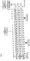
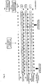
- FIG. 1 An example of the casting line for mold of the present invention is explained by referring to Figs. 1-6 .
- Fig. 1 in the casting line for mold many flaskless vertical molds 2 that were molded by a high speed molding machine are lined up and extended to the left direction while the mold forms a cavity for product by the cavity-surfaces being joined.
- Rails 3 are laid parallel to the group of the molds, and the two carriages for the pouring ladles (hereafter, also called “the first carriage 4" and “the second carriage 5") that can run along the group of molds are installed as transporting devices.
- the first carriage 4 and the second carriage 5 are provided with driving devices 6, 7, respectively (see Fig. 2 ), and both are self-propelled. Further, the first pouring ladle 8 and the second pouring ladle 9 that each can pour the molten metal into the cavity for product of the mold 2 by being tilted are disposed on the first carriage and the second carriage, respectively.
- first pouring ladle 8 and the second pouring ladle 9 can be transported onto and out of the first carriage 4 and the second carriage 5, respectively, by the respective first and the second roller conveyors 10, 11, that are installed perpendicularly to the rails 3.
- the first and the second roller conveyors 10, 11, each have rotatable rollers.
- the first pouring ladle 8 of the first carriage 4 plays a main role in pouring the molten metal while the second pouring ladle 9 of the second carriage 5 plays a supplementary role in pouring.
- first carriage 4 and the first pouring ladle 8 constitute the first automatic pouring machine 51 and the second carriage 5 and the second pouring ladle 9 constitute the second automatic pouring machine 52.
- first automatic pouring machine 51 and the second automatic pouring machine 52 work by their coordinated operation in cooperation with the system for controlling pouring machines 53 that is explained below, as equipment for pouring the molten metal 50 that pours the molten metal into a number of molds that are sent out in a row from the molding machine.
- a control panel that controls the operations of the molding machine 1 As a control panel that controls the operations of the molding machine 1, the movement of the first carriage 4 and the second carriage 5, a ground control panel 12 installed on the ground, and the control panel 13 of the first carriage 4, and the control panel 14 that are installed on the first carriage 4 and the control panel 14 of the second carriage 5, respectively, are provided.
- the ground control panel 12 is electrically connected to the control panel 13 of the first carriage 4 and to the control panel 14 of the second carriage 5 by cable 17 that is supported by a number of pulleys 15 attached to the rails 16.
- the main control device 12a attached to the ground control panel 12, the control device for controlling the first pouring machine 13a that is disposed on the first carriage 4, and the control device for controlling the second pouring machine 14a that is disposed on the second carriage 5, constitute a system for controlling pouring machines 53 that coordinates the operations of the first automatic pouring machine and the second automatic pouring machine.
- the equipment for pouring the molten metal 50 of the present invention comprises two automatic pouring machines, i.e., the first and second automatic pouring machines, and a system for controlling pouring machines, wherein the first automatic pouring machine 51 comprises:
- the main control device 12a that is disposed in the ground control panel 12 comprises:
- the data that are stored in the device for storing the data on mold 18 comprises at least information for each mold on the pattern that was used for molding and the information for each mold on whether the first pouring ladle 8 is scheduled to pour the molten metal into the mold, and whether the second pouring ladle 9 has completed the pouring.
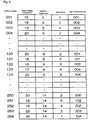
- the device for storing the data on mold 18 comprises a section for storing pattern-number 22, which section stores the data for the patterns that were used for molding molds 2, a section for storing information on completion of pouring 23, which section stores the data as to whether the pouring is completed for each mold, and a section for storing the number of pouring machine 24, which section stores either one of the reference numbers for the first pouring ladle 8 or the second pouring ladle 9.
- the section for storing pattern-number 22, the section for storing information on completion of pouring 23, and the section for storing the number of pouring machine 24 each store the data and the number of the mold that corresponds to the data. Also, the section for storing pattern-number 22 stores the type of pattern that is used for molding mold by the number that is allocated to each type of pattern.
- the section for storing information on completion of pouring 23 stores the information on whether the pouring is complete or not by giving either number "0" or "1.”
- the number “0” denotes "the pouring is not completed” and the number “1” denotes "the pouring is completed.”
- the section for storing the number of pouring machine 24 stores the information as to whether the first pouring ladle 8 is scheduled to pour or the first pouring ladle 8 has completed the pouring. Also, it stores the information as to whether the second pouring ladle 9 has completed the pouring or the second pouring ladle is in another state. Each of these states is referred to by the numbers "0", "1," or "2" and stored in the section for storing the number of pouring machine 24.
- the number “1” includes both states where the first pouring ladle 8 is scheduled to pour the molten metal or the first pouring ladle 8 has completed the pouring.
- the ground control panel 12 comprises a display that can show the data on molds that are stored in the device for storing the data on mold 18.
- the display shows items that include "the numbers of the mold” that are the sequential numbers (numbers in order) given to the molds of the casting line for mold, "the numbers of the patterns” that are given depending on the type of pattern that is used for molding molds for the casting line for mold, "the information on completion of pouring” as to whether the pouring of each mold of the casting line for mold has been completed or has not yet been completed, and the "number of the pouring machine” (machine no.) for each of the first carriage 4 and the second carriage 5.
- the control device for controlling the first pouring machine 13a of the control panel of the first carriage 13 controls each component of the first automatic pouring machine 51. More specifically, as shown in Fig. 3 , the control device for controlling the first pouring machine 13a comprises a device for receiving the data on mold 25 a device for storing the data on mold 26, a device for calculating the accumulated weight of the molten metal poured 27, a device for receiving information on the weight 28, a device for calculating the number of the molds into which that the molten metal can be poured 29, a device for indicating the number of the pouring machine 30, a device for storing the relationship of the positions 31, a device for determining the mold into which the molten metal is poured 32, a device for directing the operation of pouring 36, a device for receiving a signal for completion of pouring 37, and a device for entering the information on the completion of pouring 38.
- the device for receiving the data on mold 25 receives from the device for storing the data on mold 18 of the main control device 12a the data on mold that include the number of the pattern corresponding to the number of the mold, the information on completion of pouring, and the number of the pouring machine.
- the device for storing the data on mold 26 works as data table for the control device for controlling the first pouring machine 13a and stores the data on mold that the device for receiving the data on mold 25 received.
- the device for storing the data on mold 26 stores the data corresponding to the number of the pattern, such as the required "weight of the molten metal poured,” “quality of the molten metal,” and “data at the sprue” and the “data on the locus of the pouring” that show the speed of the tilting and the angle of tilting of the pouring ladle when the molten metal is poured.
- the device for calculating the accumulated weight of the molten metal poured 27 calculates the accumulated weight of the molten metal that is scheduled to be poured based on the information that is stored in the device for storing the data on mold 26. Namely, the device for calculating the accumulated weight of the molten metal poured 27 calculates the accumulated weight of the molten metal that is scheduled to be poured into the molds where the pouring of the molten metal has not been completed, in the order of the number of the molds, based on "the number of the molds," “the number of the patterns,” “the information on completion of pouring,” etc.
- the weight of the molten metal for each mold is stored, for example, in the device for storing the data on mold 26, where the number is referred to by number of its pattern.
- the device for calculating the accumulated weight of the molten metal poured 27 can identify the molds where the molten metal is poured continuously by the first pouring ladle 8 into such molds without having the pouring ladle replaced by another ladle, as explained below.
- the device for receiving information on the weight 28 receives the information on the weight of the molten metal in the pouring ladle 8 from a device for detecting the weight of the molten metal (not shown) that detects the weight of the molten metal in the first pouring ladle 8.
- This device for detecting the weight of the molten metal is, for example, a load cell.
- the device for receiving information on the weight 28 receives the information on the weight of the molten metal in the pouring ladle 8 that was detected by the load cell.
- the device for calculating the number of the molds into which the molten metal can be poured 29 calculates the numbers of molds and identifies the molds into which the molten metal can be poured, where the molds into which the molten metal have not yet been poured are counted starting from the leading mold in the running direction of the molds, and where the count is made based on the information on the weight of the molten metal in the pouring ladle and the information on the pattern of each mold that are received from the device for receiving the data on mold 25 and the device for receiving information on the weight 28.
- the device for calculating the number of the molds into which the molten metal can be poured 29 calculates the number of molds into which the first pouring ladle 8 can pour the molten metal.
- the device for calculating the number of the molds into which the molten metal can be poured 29 can identify the last mold into which the first pouring ladle 8 can pour the molten metal without being replaced by the other ladle where the molten metal is poured into the molds in the order that starts from the leading mold of the molds that is yet to be filled.
- the device for calculating the number of the molds into which the molten metal can be poured 29 determines the last mold, into which the molten metal can be poured by comparing the weight of the molten metal in the ladle with the accumulated weight of the molten metal that is to be poured into the molds and identifying the mold, which is the last mold but one, where the accumulated weight of the molten metal to the last mold first exceeds the weight of the molten metal in the ladle.
- the device for indicating the number of the pouring machine 30 instructs the device for storing the data on mold 18 of the main control device 12a to enter the data, assuming that the pouring is carried out by the first pouring ladle 8 into the molds, the numbers of which molds are calculated by the device for calculating the number of the molds that the molten metal can be poured 29. More particularly, for information on "the number of pouring machine" that is stored in the section for storing the number of pouring machine 24, a "1" is each entered into the data for each mold that is scheduled to be filled with the molten metal.
- the device for calculating the accumulated weight of the molten metal poured 27, the device for calculating the number of the molds into which the molten metal can be poured 29, and the device for indicating the number of the pouring machine 30 are explained to have each function that is stated above. But a composite device that has all these functions in one body can be used.
- the device for indicating the number of the pouring machine 30 calculates the numbers of molds and identifies the molds into which the molten metal can be poured, where the molds into which the molten metal have not yet been poured, are counted starting from the leading mold in the running direction of the molds, and where the counting is made based on the information on the weight of the molten metal in the pouring ladle and the information on the pattern of each mold that are received from the device for receiving the data on mold 25 and device for receiving information on the weight 28. Then the data can be entered into the device for storing the data on mold 18 of the main control device, assuming that the numbers of the molds thus calculated are the molds into which the first pouring ladle is scheduled to pour the molten metal.
- the system for controlling pouring machines 53 of the present invention has a push button, etc, attached to the ground control panel 12 as a device for identifying a defective mold 49. If an operator finds, for example, visually, any defective mold, by using the device for identifying a defective mold 49 he or she operates the pouring ladle so that it does not pour the molten metal into such mold. If the device for identifying a defective mold 49 is operated, the information on the number of the pouring machine" in the section for storing the number of pouring machine 24 is changed from "0" or "1" to "x.”
- the device for identifying a defective mold 49 can be disposed at the control panel of the first carriage 13 or the control panel of the second carriage 14 in place of the ground control panel 12.
- the devices for identifying a defective mold 49 can be placed at plurality of positions.
- the device for calculating the accumulated weight of the molten metal poured 27, the device for indicating the number of the pouring machine 30, etc. can detect from the device for receiving the data on mold 25, etc., that the information in the section for storing the number of pouring machine 24 has been changed by the devices for identifying a defective mold 49. Then they determine if the number of the pouring machine for the mold that comes after the mold for which the number of the pouring machine has been changed to "x" is changed.
- the device for indicating the number of the pouring machine 30 instructs the device for storing the data on mold 18 of the main control device 12a to enter such a change.
- the device for indicating the number of the pouring machine 30, etc. also function as a device for changing the number of the pouring machine.
- the device for storing the relationship of the positions 31 stores the position of the first carriage 4.
- the device for determining the mold into which the molten metal is poured 32 determines to pour the molten metal by the first pouring ladle 8 into the leading mold (the mold that has the smallest number of the mold) in the direction of the transport of the molds, which molds are scheduled to be poured by the first pouring ladle 8.
- the device for determining the mold into which the molten metal is poured 32 determines to pour the molten metal into the leading mold (the mold that has the smallest number of the molds) in the direction of the transport of the molds by the first pouring ladle 8, when the molds that are registered as having "1" by the section for storing the number of pouring machine 24 are transported into the predetermined area.
- the predetermined area can include, for example, the area where the first pouring ladle 8 can move driven by the first carriage 4 or within the area that is separated by more than a predetermined distance from the position of the second pouring ladle 9, which position is determined by the information on the position of the second carriage 5.
- the first pouring ladle 8 pours the molten metal into the molds that are registered as having "1" when the molds are transported into "the predetermined area.” But by providing the base position for the first pouring ladle 8 the first pouring ladle 8 can also be made to pour the molten metal into the leading mold (the mold that has the smallest number of the molds) in the direction of the transport of the molds when the mold that is registered as having "1" by the section for storing the number of pouring machine 24 is transported before the base position for the first pouring ladle 8 (the corresponding position).
- the device for directing the operation of pouring 36 instructs the first carriage 4 to move and the first pouring ladle 8 to start the pouring into the molds that were determined by the device for determining the mold into which the molten metal is poured 32. More specifically, the device for directing the operation of pouring 36 has the function of instructing the first carriage 4 to move based on the information on the current position that is stored in the device for storing the relationship of the positions 31 and based on the information on transporting a mold received by the device for receiving the data on mold 25.
- the device for directing the operation of pouring 36 has the function of instructing the pouring ladle to pour the molten metal into the molds corresponding to the types of patterns used for molding molds based on "the data on the locus of the pouring," etc., that are stored in the device for storing the data on mold 26.
- the device for receiving a signal for completion of pouring 37 receives a signal that the pouring is completed from a device for detecting the completion of pouring such as a sensor
- the device for receiving a signal for completion of pouring 37 sends the information to the device for entering the information on the completion of pouring 38.
- the device for entering the information on the completion of pouring 38 that has received the information from the device for receiving a signal for completion of pouring 37 instructs the device for storing the data on mold 18 of the main control device 12a to enter the data.
- the device for storing the data on mold 18 that has received the instructions to enter the data changes "0" to "1" in "the information on the completion of pouring" stored in the section for storing information on completion of pouring 23.
- the control device for controlling the second pouring machine 14a that is disposed on the control panel for the second carriage 14 controls various components of the second automatic pouring machine 52. More particularly, as shown in Fig. 3 , the control device for controlling the second pouring machine 14a comprises a device for receiving the data on mold 39, a device for storing the data on mold 40, a device for storing the relationship of the positions 41, a device for determining the mold into which the molten metal is poured 46, a device for directing the operation of pouring 44, a device for receiving a signal for completion of pouring 45, and device for entering the information on the completion of pouring 47.
- the device for receiving the data on mold 39 receives the data on mold such as the numbers of the patterns which correspond to the numbers of the molds from the device for storing the data on mold 18 of the main control device 12a, the information on the completion of pouring, the numbers of the pouring machines, etc.
- the device for storing the data on mold 40 works as the data table for the control device for controlling the second pouring machine 14a and stores the data on mold that the device for receiving the data on mold 39 has received.
- the device for storing the data on mold 40 stores the necessary, the data corresponding to the numbers of the patterns that were used for molding, such as "weight of the molten metal poured,” “quality of the molten metal,” and “data at the sprue” and the “data on the locus of the pouring” that show the speed of tilting and the angle of tilting of the pouring ladle when the molten metal is poured.
- the device for storing the relationship of the positions 41 stores the position of the second carriage 5.
- the device for determining the mold into which the molten metal is poured 46 determines the mold into which the molten metal is poured, of which the pouring is made based on the data on mold received by the device for receiving the data on mold 39 and based on the information on the current position of the second carriage 5.
- the device for determining the mold into which the molten metal is poured 46 determines to pour the molten metal into the molds within "the predetermined area," which molds are other than those, into which the first pouring ladle 8 is scheduled to pour the molten metal.
- the device for determining the mold into which the molten metal is poured 46 determines to pour the molten metal into the leading mold (the mold that has the smallest number of the molds) in the direction of the transport of the molds by the second pouring ladle 9, when the molds that are registered as having "0" by the section for storing the number of pouring machine 24 are transported into the predetermined area.
- the wording "the predetermined area" can include, for example, the area where the second pouring ladle 9 can move driven by the second carriage 5 or within the area that is separated by more than a predetermined distance from the position of the first pouring ladle 8, which position is determined by the information on the position of the first carriage 4.
- the second pouring ladle 9 pours the molten metal into the molds that are registered as having "0" when the molds are transported into "the predetermined area.” But by providing the base position for the second pouring ladle 9 the second pouring ladle 9 can also be made to pour the molten metal into the leading mold (the mold that has the smallest number of the molds) in the direction of the transport of the molds when the mold that is registered as having "0" by the section for storing the number of pouring machine 24 is transported before the base position for the second pouring ladle 9 (the corresponding position).
- the device for directing the operation of pouring 44 instructs the second carriage 5 to move and the second pouring ladle 9 to start the pouring into the molds that are determined by the device for determining the mold into which the molten metal is poured 46. More specifically, the device for directing the operation of pouring 44 has the function of instructing the second carriage 5 to move based on the information on the current position that is stored in the device for storing the relationship of the positions 41 and based on the information on transporting a mold received by the device for receiving the data on mold 39.
- the device for directing the operation of pouring 44 has the function of instructing the pouring ladle to pour the molten metal into the molds corresponding to the types of patterns used for molding the molds based on "the data on the locus of the pouring," etc., that are stored in the device for storing the data on mold 40.
- the device for receiving a signal for completion of pouring 45 receives a signal that the pouring is completed, from a device for detecting the completion of pouring such as a sensor, the device for receiving a signal for completion of pouring 45 sends the information to the device for entering the information on the completion of pouring 47.
- the device for entering the information on the completion of pouring 47 that has received the information from the device for receiving a signal for completion of pouring 45 instructs the device for storing the data on mold 18 of the main control device 12a to enter the data.
- the device for storing the data on mold 18 that has received the instructions to enter the data changes "0" to "1” in "the information on the completion of pouring” stored in the section for storing information on completion of pouring 23 and changes "the number of the pouring machine” from "0" to "2” in the section for storing the number of pouring machine 24.
- the control panel of the first carriage 13 and the control panel of the second carriage 14 each have a display that can show the data on molds that are stored in the devices for storing the data on mold 26, 40, respectively.
- the display shows items that include "the numbers of the patterns” that are given depending on the type of patterns that are used for molding molds for the casting line for mold, the "weight of the molten metal poured,” which is the weight of the molten metal poured into the mold using the pattern, and the "quality of the molten metal” that is poured into the mold using the pattern and that is stored by the number, the "data at the sprue,” which data specify the position of the sprue of the mold by the number, and "the data on the locus of the pouring,” which records the data on the locus of the pouring for each pouring ladle.
- the data on the locus of the pouring refer to the data on the locus of the pouring for each pouring ladle when it
- the equipment for pouring the molten metal 50 has the first automatic pouring machine 51 and the second automatic pouring machine 52 at fixed positions, while neither the first pouring ladle 8 nor the second pouring ladle is installed in the respective pouring machines. Then the first pouring ladle 8 that has received the molten metal is transported into the first automatic pouring machine 51 by a first roller conveyor 10. After the first pouring ladle 8 is installed in the first automatic pouring machine 51, the molten metal is measured by a device for measuring the weight of the molten metal (not shown) (for example, a load cell) and the device for receiving information on the weight 28 receives the information on the weight of the molten metal in the first pouring ladle 8. Likewise the second pouring ladle 9 is transported into the second automatic pouring machine 52 by a second roller conveyor 11 and the second pouring ladle 9 is installed in the second automatic pouring machine 51.
- the second automatic pouring machine 52 may comprise a detecting device such as a load cell, etc., and a device for receiving information on the weight, which device receives the weight that is detected by the detecting device.
- a search for "1" is carried out in the numbers "1" of the pouring machine in the section for storing the number of pouring machine 24 of the device for storing the data on mold 18 of the ground control panel 12, starting from the downstream end of the line of the molds, which end is opposite to the end of the line of the casting line where the molding machine 1 is installed.
- the position (A) in the section for storing the number of pouring machine 24, which position (A) corresponds to the position (B) in the section for storing information on completion of pouring 23, which position (B) having the first "0," which means that the pouring is not completed, is the position of the mold into which the molten metal is next to be poured.
- the number of the mold, etc., of this mold is entered into and stored in the device for storing the relationship of the positions 31 of the control panel for the first carriage 13.
- the number of the pattern corresponding to the position for pouring of the first carriage 4 is retrieved by the device for receiving the data on mold 25.
- the control panel for the first carriage 13 retrieves the information on the mold into which the molten metal is poured and which mold was determined by the device for determining the mold into which the molten metal is poured 32. More specifically, as shown in Fig.
- the information includes the weight of the molten metal to be poured, the quality of the molten metal, the data at the sprue, and the data on the locus of the pouring, corresponding to the number of the pattern stored in the device for storing the data on mold 26.
- the device for determining the mold into which the molten metal is poured 32 sends a signal to the device for directing the operation of pouring 36 when the mold into which the molten metal is poured is transported into the predetermined area, that is, when the mold is moved to the position that corresponds to, for example, the base position, etc., of the first carriage 4.
- the first pouring ladle 8 starts the pouring.
- the position in the device for storing the relationship of the positions 31 is renewed after the first carriage 4 is moved to the position for pouring.
- the information to the effect is received by the device for receiving a signal for completion of pouring 37.
- the device for entering the information on the completion of pouring 38 has the symbol "1," which denotes the completion of pouring, entered into the position in the section for storing information on completion of pouring 23.
- the number of the molds into which the molten metal can be poured is calculated by the device for calculating the number of the molds into which the molten metal can be poured 29 via the device for calculating the accumulated weight of the molten metal poured 27, wherein the positions of the molds having a number of the mold of "0" in the section for storing the number of pouring machine 24, which number "0" denotes that the pouring machine is not determined, are searched in the opposite direction of the number of the molds, while the numbers of the patterns corresponding to the molds are stored through the device for receiving the data on mold 25, and the weight of the molten metal to be poured for each number of the pattern is retrieved from the device for storing the data on mold 26.
- the number "1" is booked in the section for storing pattern-number 22 of the device for storing the data on mold 18 through the device for indicating the number of the pouring machine 30.
- the device for indicating the number of the pouring machine 30 is used during the pouring of the molten metal. But it can be used only when the supply of the molten metal is complete or only when the device for identifying a defective mold 49 is operated, as is described above.
- a search is carried out in the section for storing pattern-number 22 in the downward direction, that is, in the direction from the second carriage 5 toward the first carriage 4 and stops before "1" in the first carriage 4, which "1" denotes the number of the first pouring machine. Then "0,” which shows that the pouring is not completed, is detected after a search is made in the section for storing information on completion of pouring 23.
- the device for determining the mold which the molten metal is poured into 46 retrieves the data from the device for storing the data on mold 40. More specifically, the device for determining the mold which the molten metal is poured into 46 retrieves the weight of the molten metal to be poured, the quality of the molten metal, the data at the sprue, and the data on the locus of the pouring from the various data on mold as are shown in Fig. 5 . Then after the second carriage 5 is moved to the position for pouring by the instructions of the device for directing the operation of pouring 44, the second pouring ladle 9 starts pouring.
- the control panel for the second carriage 14 changes the data on the position in the device for storing the relationship of the positions 41.
- the device for receiving a signal for completion of pouring 45 instructs the device for entering the information on the completion of pouring 47 to enter "1," which denotes "the completion of the pouring" of the mold at the position for pouring, into the section for storing information on completion of pouring 23.
- the data on the quality of the molten metal are crosschecked to see if they match the data of the reference number for the first pouring ladle 8, which data were stored in advance. Then, the first pouring ladle 8 starts pouring after the section for storing information on completion of pouring 23 of the device for storing the data on mold 18 confirms that the data in the number of the mold is given as "0," which shows that the pouring is not completed. Thus the first pouring ladle 8 pours the molten metal into the mold 2 that is at the position for pouring based on the data on the locus of the pouring and stops pouring when the pouring reached the scheduled quantity. Then "1" is entered into the section for storing information on completion of pouring 23 to show that the pouring is completed.
- the molding machine 1 When the molding machine 1 is ready to move the current mold, i.e., the mold 2, for which the pouring of the molten metal has been completed, and if, in the ground control panel 12, a signal is sent from a device for sending a signal for completion of molding 19 to the device for receiving a signal for completion of molding 20, the mold 2 is transported by a distance of one mold. Then the number of the pattern corresponding to the first mold 2, is stored as the information on the first mold of molds 2 in the section for storing pattern-number 22 and "0" is entered into the section for storing information on completion of pouring 23 and the section for storing the number of pouring machine 24.
- the numbers, including the reference number for the mold 2, which is at the position for pouring of the second carriage 5 is issued, and the device for storing the data on mold 18 instructs the section for storing pattern-number 22 to send the number of the pattern for the mold 2 which is at the position for pouring to the device for receiving the data on mold 39, which number is then sent to and stored in the device for storing the data on mold 40 of the second carriage 5.
- the weight of the molten metal to be poured, the quality of the molten metal, the data at the sprue, and the data on the locus of the pouring, corresponding to the number of the pattern at the position for pouring are obtained from the device for storing the data on mold 40 via the device for determining the mold into which the molten metal is poured 46 of the second carriage 5.
- the molten metal is poured, as in the first pouring ladle 8, into the mold 2 according to the data on the locus of the pouring.
- the ladle is tilted back and the pouring stops.
- "1," which denotes the completion of pouring is entered into the section for storing information on completion of pouring 23.
- the method of pouring that uses two automatic pouring machines is one wherein the operations of two automatic pouring machines are controlled so that the operations of the first automatic pouring machine and the second automatic pouring machine are coordinated so as to have the molten metal be poured into each of a number of molds of a casting line for mold, which molds are sent out in a row from the molding machine, where a table of the data on molds is prepared that include the numbers of the patterns used for molding each of the molds, the information on the conditions for pouring each mold, and the number of the pouring machine that was used for pouring. Based on this table the method carries out the pouring the molten metal by coordinating the operations of the molding machine and the two automatic pouring machine.
- the method of pouring that uses the pouring equipment 50 is one wherein the operations of two automatic pouring machines are controlled so that the operations of the first automatic pouring machine and the second automatic pouring machine are coordinated so as to have the molten metal be poured into each of a number of molds of a casting line for mold, which molds are sent out in a row from the molding machine, the first automatic pouring machine comprising the first carriage that can run in the direction of the molds of the casting line for mold, which molds are lined up in a row and the first pouring ladle that is attached to and transported by the first carriage and the second automatic pouring machine comprising the second carriage that can run in the direction of the molds of the casting line for mold, which molds are lined up in a row and the second pouring ladle that is attached to and transported by the second carriage, and wherein the method comprises the equipment used for the method, the equipment comprising:
- the system for controlling pouring machines 53 and the equipment for pouring the molten metal 50 comprise:
- the system for controlling pouring machines 53 and the equipment for pouring the molten metal 50 of the present invention have the first automatic pouring machine 51 installed at the position which is downstream of the second automatic pouring machine 52. That is, the first automatic pouring machine 51 is installed nearer to the leading mold in the running direction of the molds than the second automatic pouring machine 52 is.
- the system for controlling pouring machines 53 and the equipment for pouring the molten metal 50 of the present invention having this characteristic in the layout combined with the formation of the devices, etc., as stated above, can prevent the two pouring ladles, i.e., the first pouring ladle 8 and the second pouring ladle 9, from mutually interfering, even if their movements are limited to smaller area.
- the size of the equipment for pouring the molten metal 50 and the casting line for mold can be minimized.
- the system for controlling pouring machines 53, the equipment for pouring the molten metal 50, and the method of pouring of the present invention are controlled, based on the table of data on molds, which table of data is prepared so that it includes the numbers of the patterns used for molding molds, the information on the conditions for pouring each mold, and the number of the pouring machine that was used for pouring, such that the pouring of the molten metal can be carried out by the coordinated operation of the molding machine and the two automatic pouring machines.
- the system for controlling pouring machines 53, the equipment for pouring the molten metal 50, and the method of pouring of the present invention can produce effects where, by appropriately coordinating the operations of the molding machine and the two automatic pouring machines, the molten metal can be poured into each of a number of molds of a casting line for mold, which molds are sent out in a row from the molding machine.
Landscapes
- Engineering & Computer Science (AREA)
- Mechanical Engineering (AREA)
- Casting Support Devices, Ladles, And Melt Control Thereby (AREA)
- Casting Devices For Molds (AREA)
Claims (7)
- System (53)zur Steuerung von Gießmaschinen, das die Abläufe von zwei automatischen Gießmaschinen (51, 52) steuert, sodass die Abläufe einer ersten automatischen Gießmaschine (51) und einer zweiten automatischen Gießmaschine (52) koordiniert werden, damit geschmolzenes Metall in jede von einer Reihe von Gussformen (2) einer Gießstraße für Gussformen gegossen wird, wobei die Gussformen (2) in einer Reihe von einer Gussformmaschine (1) aus gesendet werden,
wobei die erste automatische Gießmaschine (51) einen ersten Schlitten (4), der in die Richtung der Reihe von Gussformen (2) einer Gießstraße für Gussformen bewegt werden kann, wobei die Gussformen (2) in einer Reihe aufgereiht sind, und eine erste Gießpfanne (8), die an dem ersten Schlitten (4) befestigt ist und von ihm transportiert wird, umfasst, und
die zweite automatische Gießmaschine (52) einen zweiten Schlitten (5), der in die Richtung der Gussformen (2) der Gießstraße für Gussformen bewegt werden kann, wobei die Gussformen (2) in einer Reihe aufgereiht sind, und eine erste Gießpfanne (9), die an dem zweiten Schlitten (5) befestigt ist und von ihm transportiert wird, umfasst,
das System (53) zum Steuern von Gießmaschinen umfassend:eine Hauptsteuervorrichtung (12a), die an einem auf dem Boden angeordneten Bodenbedienpult (12) befestigt ist;eine Steuervorrichtung (13a) zum Steuern der ersten Gießmaschine, die auf einem Bedienpult (13) angeordnet ist, das auf dem ersten Schlitten (4) montiert ist; undeine Steuervorrichtung (14a) zum Steuern der zweiten Gießmaschine, die auf einem Bedienpult (14) angeordnet ist, das auf dem zweiten Schlitten (5) montiert ist; wobei die Hauptsteuervorrichtung (12a) eine Vorrichtung (18) zum Speichern der Daten über die Gussform umfasst, wobei die Vorrichtung (18) die Daten über die Gussform und die Nummer der Gussform für jede Gussform speichert, die Daten über die Gussform, die in der Vorrichtung (18) zum Speichern der Daten über eine Gussform gespeichert sind, mindestens die Information für jede Gussform auf dem Muster umfassen, das zum Gießen jeder Gussform verwendet wurde, und auch die Information für jede Gussform umfasst, ob die erste Gießpfanne (8) dafür vorgesehen ist, das geschmolzene Metall in eine Gussform zu gießen und ob die zweite Gießpfanne (9) das Gießen des geschmolzenen Metalls in die Gussform beendet hat;wobei die Steuervorrichtung (13a) zum Steuern der ersten Gießmaschine umfasst: eine erste Vorrichtung (25) zum Empfangen der Daten über die Gussform, wobei die Vorrichtung (25) die Daten über die Gussform von der Vorrichtung (18) zum Speichern der Daten über die Gussform der Hauptsteuervorrichtung (12a) empfängt;
eine Vorrichtung (28) zum Empfangen von Information über das Gewicht, wobei die Vorrichtung (28) Information über das Gewicht des geschmolzenen Metalls in der Gießpfanne (8) von einer Erkennungsvorrichtung empfängt, die das Gewicht des geschmolzenen Metalls in der ersten Gießpfanne (8) erkennt;
eine Vorrichtung (30) zum Angeben der Nummer der Gießmaschine, wobei die Vorrichtung die Anzahl der Gussformen berechnet und die Gussformen, in welche das geschmolzene Metall gegossen werden kann, identifiziert, wobei die Gussformen beginnend mit der führenden Gussform in Laufrichtung der Gussformen, in welche das geschmolzene Metall noch nicht gegossen wurde, gezählt werden und wobei die Berechnung basierend auf der Information über das Gewicht des geschmolzenes Metalls in der Gießpfanne (8) und über das Muster jeder Gussform erfolgt, wobei die Information von der ersten Vorrichtung (25) zum Empfangen der Daten über die Gussform und der Vorrichtung (28) zum Empfangen von Information über das Gewicht empfangen wird, und wobei die Vorrichtung (30) zum Angeben der Nummer der Gießmaschine die Vorrichtung (18) zum Speichern der Daten über die Gussform der Hauptsteuervorrichtung (12a) anweist, die Daten über die Gussformen, die als diejenigen identifiziert werden, in welche die erste Gießpfanne (8) das geschmolzene Metall gießen soll, einzugeben;
eine Vorrichtung (32) zum Bestimmen der Gussformen, in welche die erste Gießmaschine das geschmolzene Metall gießt, wobei die Vorrichtung (32) die Gussform ermittelt, in welche das geschmolzene Metall basierend auf den Daten über die Gussform, die von der ersten Vorrichtung (25) zum Empfangen der Daten über die Gussform und basierend auf der Information über die aktuellen Positionen der Gussform empfangen wurden, gegossen werden soll;
eine Vorrichtung (36) zum Steuern des Ablaufs des Gießens durch die erste Gießpfanne, wobei die Vorrichtung (36) die Anweisungen gibt, die Bewegung des ersten Schlittens (4) und den Beginn des Gießens durch die erste Gießpfanne (8) zu bewirken, damit die erste Gießpfanne (8) das geschmolzene Metall in die Gussformen gießen kann, die von der Vorrichtung (32) zum Bestimmen der Gussformen, in welche die erste Gießmaschine das geschmolzene Metall gießt, identifiziert werden; wobei die Steuervorrichtung (14a) zum Steuern der zweiten Gießmaschine umfasst:eine zweite Vorrichtung (39) zum Empfangen der Daten über die Gussform, wobei die Vorrichtung (39) die Daten über die Gussform von der Vorrichtung (18) zum Speichern der Daten über die Gussform der Hauptsteuervorrichtung (12a) empfängt;eine Vorrichtung (46) zum Bestimmen der Gussformen, in welche die zweite Gießmaschine das geschmolzene Metall gießt, wobei die Vorrichtung (46) die Gussform ermittelt, in welche das geschmolzene Metall basierend auf den Daten über die Gussform, die von der zweiten Vorrichtung (39) zum Empfangen der Daten über die Gussform und basierend auf der Information über die aktuellen Positionen der Gussform empfangen wurden, gegossen werden soll;eine Vorrichtung (44) zum Steuern des Ablaufs des Gießens durch die zweite Gießpfanne, wobei die Vorrichtung (44) die Anweisungen gibt, die Bewegung des zweiten Schlittens (5) und den Beginn des Gießens durch die zweite Gießpfanne (9) zu bewirken, damit die zweite Gießpfanne (9) das geschmolzene Metall in die Gussformen gießen kann, die von der Vorrichtung (46) zum Bestimmen der Gussformen, in welche die zweite Gießmaschine das geschmolzene Metall gießt, bestimmt werden; - System (53) zum Steuern von Gießmaschinen nach Anspruch 1, wobei, wenn die Gussform, in welche die erste Gießpfanne (8) das geschmolzene Metall gießen soll, wobei das Gießen durch die erste Gießpfanne (8) von der Vorrichtung (30) zum Angeben der Nummer der Gießmaschine basierend auf den Daten über Gussformen der Vorrichtung (18) zum Speichern der Daten über die Gussform angewiesen wird, vor der ersten Gießpfanne (8) positioniert ist, die Vorrichtung (32) zum Bestimmen der Gussform, in welche die erste Gießmaschine das geschmolzene Metall gießt, bestimmt, das geschmolzene Metall durch die erste Gießpfanne (8) in die führende Gussform in Transportrichtung der Gussform (2) zu gießen.
- System (53) zum Steuern von Gießmaschinen nach Anspruch 1 oder 2, wobei, wenn die Gussform, in welche die erste Gießpfanne (8) das geschmolzene Metall nicht gießen soll, wobei die Anweisungen, dass das Gießen nicht durch die erste Gießpfanne (8) erfolgen soll, von der Vorrichtung (30) zum Angeben der Nummer der Gießmaschine basierend auf den Daten über Gussformen der Vorrichtung (18) zum Speichern der Daten über die Gussform gegeben werden, vor der zweiten Gießpfanne (9) positioniert ist, die Vorrichtung (46) zum Bestimmen der Gussform, in welche die zweite Gießmaschine das geschmolzene Metall gießt, bestimmt, das geschmolzene Metall durch die zweite Gießpfanne (9) in die führende Gussform in Transportrichtung der Gussform (2) zu gießen.
- Anlage (50) zum Gießen von geschmolzenem Metall, umfassend:eine erste automatische Gießmaschine (51), die einen ersten Schlitten (4), der in die Richtung einer Reihe von Gussformen (2) der Gießstraße für Gussformen bewegt werden kann, wobei die Gussformen (2) in einer Reihe aufgereiht sind und von einer Gussformmaschine (1) gesendet werden, und eine erste Gießpfanne (8), die an dem ersten Schlitten (4) befestigt ist und von ihm transportiert wird, umfasst, undeine zweite automatische Gießmaschine (52), die einen zweiten Schlitten (5), der in die Richtung der einer Reihe von Gussformen (2) der Gießstraße für Gussformen bewegt werden kann, wobei die Gussformen (2) in einer Reihe aufgereiht sind, und eine erste Gießpfanne (9), die an dem zweiten Schlitten (5) befestigt ist und von ihm transportiert wird, umfasst, wobei die zwei automatischen Gießmaschinen (51, 52) das geschmolzene Metall in eine Anzahl von Gussformen (2) gießen, die in einer Reihe von der Gussformmaschine (1) aus gesendet werden, undein System (53) zum Steuern von Gießmaschinen, das die Abläufe von zwei automatischen Gießmaschinen (51, 52) steuert, sodass die Abläufe der ersten automatischen Gießmaschine (51) und der zweiten automatischen Gießmaschine (52) koordiniert werden,wobei das System (53 zum Steuern von Gießmaschinen umfasst: eine Hauptsteuervorrichtung (12a), die an einem auf dem Boden angeordneten Bodenbedienpult (12) befestigt ist;
eine Steuervorrichtung (13a) zum Steuern der ersten Gießmaschine, die auf einem Bedienpult (13) angeordnet ist, das auf dem ersten Schlitten (4) montiert ist; und
eine Steuervorrichtung (14a) zum Steuern der zweiten Gießmaschine, die auf einem Bedienpult (14) angeordnet ist, das auf dem zweiten Schlitten (5) montiert ist; wobei die Hauptsteuervorrichtung (12a) eine Vorrichtung (18) zum Speichern der Daten über die Gussform umfasst, welche die Daten über die Gussform und die Nummer der Gussform für jede Gussform speichert, die Daten über die Gussform, die in der Vorrichtung (18) zum Speichern der Daten über eine Gussform gespeichert sind, mindestens die Information für jede Gussform auf dem Muster umfassen, das zum Gießen jeder Gussform verwendet wurde, und auch die Information für jede Gussform umfasst, ob die erste Gießpfanne (8) dafür vorgesehen ist, das geschmolzene Metall in eine Gussform zu gießen und ob die zweite Gießpfanne (9) das Gießen des geschmolzenen Metalls in die Gussform beendet hat;
wobei die Steuervorrichtung (13a) zum Steuern der ersten Gießmaschine umfasst: eine erste Vorrichtung (25) zum Empfangen der Daten über die Gussform, wobei die Vorrichtung (25) die Daten über die Gussform von der Vorrichtung (18) zum Speichern der Daten über die Gussform der Hauptsteuervorrichtung (12a) empfängt;
eine Vorrichtung (28) zum Empfangen von Information über das Gewicht, wobei die Vorrichtung (28) eine Information über das Gewicht des geschmolzenen Metalls in der Gießpfanne (8) von einer Erkennungsvorrichtung empfängt, die das Gewicht des geschmolzenen Metalls in der ersten Gießpfanne (8) erkennt;
eine Vorrichtung (30) zum Angeben der Nummer der Gießmaschine, wobei die Vorrichtung (30) die Nummer der Gussformen berechnet und die Gussformen, in welche das geschmolzene Metall gegossen werden kann, identifiziert, wobei die Gussformen beginnend mit der führenden Gussform in Laufrichtung der Gussformen, in welche das geschmolzene Metall noch nicht gegossen wurde, gezählt werden und wobei die Berechnung basierend auf der Information über das Gewicht des geschmolzenes Metalls in der Gießpfanne (8) und über das Muster jeder Gussform erfolgt, wobei die Information von der ersten Vorrichtung (25) zum Empfangen der Daten über die Gussform und der Vorrichtung (28) zum Empfangen von Information über das Gewicht empfangen wird und wobei die Vorrichtung (30) zum Angeben der Nummer der Gießmaschine die Vorrichtung (18) zum Speichern der Daten über die Gussform der Hauptsteuervorrichtung (12a) anweist, die Daten über die Gussformen, die als diejenigen identifiziert werden, in welche die erste Gießpfanne (8) das geschmolzene Metall gießen soll, einzugeben;
eine Vorrichtung (32) zum Bestimmen der Gussformen, in welche die erste Gießmaschine das geschmolzene Metall gießt, wobei die Vorrichtung (32) die Gussform ermittelt, in welche das geschmolzene Metall basierend auf den Daten über die Gussform, die von der ersten Vorrichtung (25) zum Empfangen der Daten über die Gussform und basierend auf der Information über die aktuellen Positionen der Gussform gegossen werden soll;
eine Vorrichtung (36) zum Anweisen des ersten Schlittens, das Gießen zu beginnen, wobei die Vorrichtung (36) die Anweisungen gibt, die Bewegung des ersten Schlittens (4) und den Beginn des Gießens durch die erste Gießpfanne (8) zu bewirken, damit die erste Gießpfanne (8) das geschmolzene Metall in die Gussformen gießen kann, die von der Vorrichtung (32) zum Bestimmen der Gussformen, in welche die erste Gießmaschine das geschmolzene Metall gießt, identifiziert werden;
wobei die Steuervorrichtung (14a) zum Steuern der zweiten Gießmaschine umfasst:eine zweite Vorrichtung (39) zum Empfangen der Daten über die Gussform, wobei die Vorrichtung (39) die Daten über die Gussform von der Vorrichtung (18) zum Speichern der Daten über die Gussform der Hauptsteuervorrichtung (12a) empfängt;eine Vorrichtung (46) zum Bestimmen der Gussformen, in welche die zweite Gießmaschine das geschmolzene Metall gießt, wobei die Vorrichtung (46) die Gussform ermittelt, in welche das geschmolzene Metall basierend auf den Daten über die Gussform, die von der zweiten Vorrichtung (39) zum Empfangen der Daten über die Gussform und basierend auf der Information über die aktuellen Positionen der Gussform empfangen wurden, gegossen werden soll;eine Vorrichtung (44) zum Anweisen der zweiten Gießpfanne, das Gießen zu beginnen, wobei die Vorrichtung (44) die Anweisungen gibt, die Bewegung des zweiten Schlittens (5) und den Beginn des Gießens durch die zweite Gießpfanne (9) zu bewirken, damit die zweite Gießpfanne (9) das geschmolzene Metall in die Gussformen gießen kann, die von der Vorrichtung (46) zum Bestimmen der Gussformen ermittelt werden, in welche die zweite Gießmaschine das geschmolzene Metall gießt; - Anlage (50) zum Gießen des geschmolzenen Metalls nach Anspruch 4, wobei, wenn die Gussform, in welche die erste Gießpfanne (8) das geschmolzene Metall gießen soll, wobei das Gießen durch die erste Gießpfanne (8) von der Vorrichtung (30) zum Angeben der Nummer der Gießmaschine basierend auf den Daten über Gussformen der Vorrichtung (18) zum Speichern der Daten über die Gussform angewiesen wird, vor der ersten Gießpfanne (8) positioniert ist, die Vorrichtung (32) zum Bestimmen der Gussform, in welche die erste Gießmaschine das geschmolzene Metall gießt, bestimmt, das geschmolzene Metall durch die erste Gießpfanne (8) in die führende Gussform in Transportrichtung der Gussform (2) zu gießen.
- Anlage (50) zum Gießen des geschmolzenen Metalls nach Anspruch 4 oder 5, wobei, wenn die Gussform, in welche die erste Gießpfanne (8) das geschmolzene Metall nicht gießen soll, wobei die Anweisungen, dass das Gießen nicht durch die erste Gießpfanne (8) erfolgen soll, von der Vorrichtung (30) zum Angeben der Nummer der Gießmaschine basierend auf den Daten über Gussformen der Vorrichtung (18) zum Speichern der Daten über die Gussform gegeben werden, vor der zweiten Gießpfanne (9) positioniert ist, die Vorrichtung (46) zum Bestimmen der Gussform, in welche die zweite Gießmaschine das geschmolzene Metall gießt, bestimmt, das geschmolzene Metall durch die zweite Gießpfanne (9) in die führende Gussform in Transportrichtung der Gussform (2) zu gießen.
- Verfahren zum Gießen von geschmolzenem Metall durch eine erste automatische Gießmaschine (51) und eine zweite automatische Gießmaschine (52) in Gussformen (2), wobei das Gießen des geschmolzenen Metalls durch eine Hauptsteuervorrichtung (12a) gesteuert wird, die die Anlage (50) zum Gießen des geschmolzenen Metalls steuert, sodass die Abläufe der ersten automatischen Gießmaschine (51) und der zweiten automatischen Gießmaschine (52) koordiniert werden, damit das geschmolzene Metall in jeder von einer Anzahl von Gussformen (2) einer Gießstraße für Gussformen gegossen wird, wobei die Gussformen (2) in einer Reihe von einer Gussformmaschine (1) aus gesendet werden, wobei die erste automatische Gießmaschine (51) einen ersten Schlitten (4) umfasst, der in die Richtung der Anzahl von Gussformen (2) der Gießstraße für Gussformen bewegt werden kann, wobei die Gussformen (2) in einer Reihe aufgereiht sind und eine erste Gießpfanne (8) an dem ersten Schlitten (4) befestigt ist und von ihm transportiert wird, und die zweite automatische Gießmaschine (52) einen zweiten Schlitten (5), der in die Richtung der Gussformen (2) der Gießstraße für Gussformen bewegt werden kann, wobei die Gussformen (2) in einer Reihe aufgereiht sind, und eine erste Gießpfanne (9), die an dem zweiten Schlitten (5) befestigt ist und von ihm transportiert wird, umfasst,
wobei das Verfahren das Gießen des geschmolzenen Metalls durch die erste und die zweite automatische Gießmaschine (51, 52) umfasst, wobei, basierend auf der Information von der Hauptsteuervorrichtung (12a), die sämtliche Komponenten, Vorrichtungen, usw. steuert, über die Anlage und welche eine Vorrichtung (18) zum Speichern der Daten über die Gussform umfasst, welche die Daten über Gussformen mit den entsprechenden Nummern der Gussformen speichert, während die Daten über Gussformen mindestens die Information über die Muster, die zum Gießen jeder Gussform verwendet wurden, beinhalten, wobei die Information über jede Gussform, ob die erste Gießpfanne (8) das geschmolzene Metall in die Gussform gießen soll, und auch, ob die zweite Gießpfanne (9) das Gießen beendet hat,(A) die erste Gießmaschine (51) das geschmolzene Metall durch die erste Gießpfanne (8), die von der Steuervorrichtung (13a) zum Steuern der ersten Gießmaschine gesteuert wird, gießt,
wobei die Steuervorrichtung (13a) zum Steuern der ersten Gießmaschine umfasst:eine erste Vorrichtung (25) zum Empfangen der Daten über die Gussform, wobei die Vorrichtung (25) die Daten über die Gussform von der Vorrichtung (18) zum Speichern der Daten über die Gussform der Hauptsteuervorrichtung (12a) empfängt;eine Vorrichtung (28) zum Empfangen von Information über das Gewicht, wobei die Vorrichtung (28) eine Information über das Gewicht des geschmolzenen Metalls in der Gießpfanne (8) von einer Erkennungsvorrichtung empfängt, die das Gewicht des geschmolzenen Metalls in der ersten Gießpfanne (8) erkennt;eine Vorrichtung (30) zum Angeben der Nummer der Gießmaschine, wobei die Vorrichtung (30) die Nummer der Gussformen berechnet und die Gussformen, in welche das geschmolzene Metall gegossen werden kann, identifiziert, wobei die Gussformen beginnend mit der führenden Gussform in Laufrichtung der Gussformen, in welche das geschmolzene Metall noch nicht gegossen wurde, gezählt werden und wobei die Berechnung basierend auf der Information über das Gewicht des geschmolzenes Metalls in der Gießpfanne (8) und über das Muster jeder Gussform erfolgt, wobei die Information von der ersten Vorrichtung (25) zum Empfangen der Daten über die Gussform und der Vorrichtung (28) zum Empfangen von Information über das Gewicht empfangen wird und wobei die Vorrichtung (30) zum Angeben der Nummer der Gießmaschine die Vorrichtung (18) zum Speichern der Daten über die Gussform der Hauptsteuervorrichtung (12a) anweist, die Daten über die Gussformen, die als diejenigen identifiziert werden, in welche die erste Gießpfanne (8) das geschmolzene Metall gießen soll, einzugeben;eine Vorrichtung (32) zum Bestimmen der Gussformen, in welche die erste Gießmaschine das geschmolzene Metall gießt, wobei die Vorrichtung (32) die Gussform ermittelt, in welche das geschmolzene Metall basierend auf den Daten über die Gussform, die von der ersten Vorrichtung (25) zum Empfangen der Daten über die Gussform und basierend auf der Information über die aktuellen Positionen der Gussform empfangen wurden, gegossen werden soll;eine Vorrichtung (36) zum Anweisen der ersten Gießpfanne, das Gießen zu beginnen, wobei die Vorrichtung (36) die Anweisungen gibt, die Bewegung des ersten Schlittens (4) und den Beginn des Gießens durch die erste Gießpfanne (8) zu bewirken, damit die erste Gießpfanne (8) das geschmolzene Metall in die Gussformen gießen kann, die von der Vorrichtung (32) zum Bestimmen der Gussformen, in welche die erste Gießmaschine das geschmolzene Metall gießt, identifiziert werden; und(B) die zweite Gießmaschine (52) das geschmolzene Metall durch die zweite Gießpfanne (9), die von der Steuervorrichtung (14a) zum Steuern der zweiten Gießmaschine gesteuert wird, gießt, die Steuervorrichtung (14a) zum Steuern der zweiten Gießmaschine umfassend:eine zweite Vorrichtung (39) zum Empfangen der Daten über die Gussform, wobei die Vorrichtung (39) die Daten über die Gussform von der Vorrichtung (18) zum Speichern der Daten über die Gussform der Hauptsteuervorrichtung (12a) empfängt;eine Vorrichtung (46) zum Bestimmen der Gussformen, in welche die zweite Gießmaschine das geschmolzene Metall gießt, wobei die Vorrichtung (46) die Gussform ermittelt, in welche das geschmolzene Metall basierend auf den Daten über die Gussform, die von der zweiten Vorrichtung (39) zum Empfangen der Daten über die Gussform und basierend auf der Information über die aktuellen Positionen der Gussform gegossen werden soll;eine Vorrichtung (44) zum Anweisen der zweiten Gießpfanne, das Gießen zu beginnen, wobei die Vorrichtung (44) die Anweisungen gibt, die Bewegung des zweiten Schlittens (5) und den Beginn des Gießens durch die zweite Gießpfanne (9) zu bewirken, damit die zweite Gießpfanne (9) das geschmolzene Metall in die Gussformen gießen kann, die von der Vorrichtung (46) zum Bestimmen der Gussformen ermittelt werden, in welche die zweite Gießmaschine das geschmolzene Metall gießt.
Applications Claiming Priority (3)
| Application Number | Priority Date | Filing Date | Title |
|---|---|---|---|
| JP2009209565 | 2009-09-10 | ||
| JP2010135386 | 2010-06-14 | ||
| PCT/JP2010/062070 WO2011030618A1 (ja) | 2009-09-10 | 2010-07-16 | 注湯機制御システム、注湯設備及び注湯方法 |
Publications (3)
| Publication Number | Publication Date |
|---|---|
| EP2476496A1 EP2476496A1 (de) | 2012-07-18 |
| EP2476496A4 EP2476496A4 (de) | 2017-12-20 |
| EP2476496B1 true EP2476496B1 (de) | 2019-01-23 |
Family
ID=43732293
Family Applications (1)
| Application Number | Title | Priority Date | Filing Date |
|---|---|---|---|
| EP10815216.6A Active EP2476496B1 (de) | 2009-09-10 | 2010-07-16 | System zur steuerung einer maschine zur ausgiessung von geschmolzenem metall, vorrichtung zur ausgiessung von geschmolzenem metall und verfahren zur ausgiessung von geschmolzenem metall |
Country Status (6)
| Country | Link |
|---|---|
| US (1) | US8644977B2 (de) |
| EP (1) | EP2476496B1 (de) |
| JP (1) | JP5519679B2 (de) |
| CN (1) | CN102019415B (de) |
| BR (1) | BR112012004528B1 (de) |
| WO (1) | WO2011030618A1 (de) |
Families Citing this family (15)
| Publication number | Priority date | Publication date | Assignee | Title |
|---|---|---|---|---|
| CN104936726B (zh) * | 2012-11-15 | 2016-09-07 | 新东工业株式会社 | 试件采集方法、试件数据管理方法以及试件模型 |
| US9975177B2 (en) * | 2013-04-27 | 2018-05-22 | National University Corporation University Of Yamanashi | Method for a pouring control and a storage medium for storing programs for causing a computer to carry out a process for controlling pouring |
| JP5869536B2 (ja) * | 2013-08-08 | 2016-02-24 | Kyb株式会社 | 鋳造製品の製造データ管理方法 |
| JP6244181B2 (ja) * | 2013-11-14 | 2017-12-06 | Kyb株式会社 | 鋳造設備 |
| JP6530589B2 (ja) * | 2014-05-13 | 2019-06-12 | Kyb株式会社 | 鋳造設備 |
| US10272489B2 (en) * | 2014-09-17 | 2019-04-30 | Sintokogio, Ltd. | Carriage for receiving molten metal with a mechanism for moving a ladle up and down, and a method for transporting molten metal |
| EP3266539B1 (de) * | 2015-03-04 | 2020-02-19 | Sintokogio, Ltd. | System und verfahren zum tragen von geschmolzenem metall |
| EP3378583B1 (de) * | 2015-11-16 | 2020-09-09 | Sintokogio, Ltd. | Giessanlage, verwendung und verwaltungsverfahren für gussformherstellungsdaten für eine gussform und schmelzzustandsdaten für schmelze in einer giessanlage |
| CN105710353A (zh) * | 2016-01-28 | 2016-06-29 | 山东康迈信机械有限公司 | 静压线砂模浇注方法 |
| CN106563795B (zh) * | 2016-10-26 | 2019-09-20 | 共享智能装备有限公司 | 浇注过程的控制系统及控制方法 |
| TW201832900A (zh) * | 2016-12-01 | 2018-09-16 | 日商新東工業股份有限公司 | 鑄造設備之資訊顯示系統 |
| CN107639226B (zh) * | 2017-08-31 | 2020-04-07 | 共享智能装备有限公司 | 一种铸件的柔性铸造系统 |
| CN111745150B (zh) * | 2020-08-15 | 2024-06-21 | 永红保定铸造机械有限公司 | 一种浇注系统用浇注机 |
| JP2023033113A (ja) * | 2021-08-27 | 2023-03-09 | 新東工業株式会社 | 鋳造設備制御システム |
| CN114054740B (zh) * | 2021-09-22 | 2023-05-05 | 山东杰创机械有限公司 | 一种多工位协同浇注系统的浇注方法 |
Family Cites Families (13)
| Publication number | Priority date | Publication date | Assignee | Title |
|---|---|---|---|---|
| US3821978A (en) * | 1972-12-21 | 1974-07-02 | Nat Eng Co | Automatic foundry system |
| JPS5838657A (ja) * | 1981-08-28 | 1983-03-07 | Kubota Ltd | 鋳造装置 |
| JPS63268562A (ja) * | 1987-04-24 | 1988-11-07 | Hitachi Metals Ltd | 注湯作業管理システム |
| JPH0289561A (ja) * | 1988-09-27 | 1990-03-29 | Mazda Motor Corp | 鋳込み制御装置 |
| US5701945A (en) * | 1995-09-07 | 1997-12-30 | Cmi-Equipment & Engineering | Automated spin-casting system |
| CN1218820C (zh) * | 2002-10-18 | 2005-09-14 | 常州市天创智能化技术有限公司 | 多工位浇注塑料制品的加工方法 |
| US7475716B2 (en) * | 2003-11-17 | 2009-01-13 | Hunter Automated Machinery Corporation | Foundry mold handling system with multiple dump outputs and method |
| DE20320923U1 (de) * | 2003-12-19 | 2005-06-09 | Hydro Aluminium Alucast Gmbh | Fertigungslinie zum im kontinuierlichen Durchlauf erfolgenden Herstellen von Gussteilen aus einer metallischen Schmelze, insbesondere einer Leichtmetallschmelze |
| WO2008038397A1 (en) * | 2006-09-25 | 2008-04-03 | Aisin Takaoka Co., Ltd. | Cast production line apparatus |
| TWI466740B (zh) * | 2007-02-15 | 2015-01-01 | 新東工業股份有限公司 | 自動注入方法及裝置 |
| JP2009202215A (ja) | 2008-02-29 | 2009-09-10 | Sintokogio Ltd | 注湯設備 |
| JP4667479B2 (ja) | 2008-03-03 | 2011-04-13 | 中国電力株式会社 | 杭着脱構造及び杭施工方法 |
| JP2010135386A (ja) | 2008-12-02 | 2010-06-17 | Renesas Electronics Corp | 半導体装置 |
-
2010
- 2010-07-16 WO PCT/JP2010/062070 patent/WO2011030618A1/ja not_active Ceased
- 2010-07-16 BR BR112012004528-8A patent/BR112012004528B1/pt active IP Right Grant
- 2010-07-16 EP EP10815216.6A patent/EP2476496B1/de active Active
- 2010-07-16 JP JP2011530779A patent/JP5519679B2/ja active Active
- 2010-07-16 US US13/393,134 patent/US8644977B2/en active Active
- 2010-09-10 CN CN201010280530.8A patent/CN102019415B/zh active Active
Non-Patent Citations (1)
| Title |
|---|
| None * |
Also Published As
| Publication number | Publication date |
|---|---|
| CN102019415B (zh) | 2013-06-12 |
| EP2476496A4 (de) | 2017-12-20 |
| BR112012004528A2 (pt) | 2016-03-22 |
| JP5519679B2 (ja) | 2014-06-11 |
| EP2476496A1 (de) | 2012-07-18 |
| BR112012004528B1 (pt) | 2018-01-23 |
| WO2011030618A1 (ja) | 2011-03-17 |
| US20120232688A1 (en) | 2012-09-13 |
| JPWO2011030618A1 (ja) | 2013-02-04 |
| US8644977B2 (en) | 2014-02-04 |
| CN102019415A (zh) | 2011-04-20 |
Similar Documents
| Publication | Publication Date | Title |
|---|---|---|
| EP2476496B1 (de) | System zur steuerung einer maschine zur ausgiessung von geschmolzenem metall, vorrichtung zur ausgiessung von geschmolzenem metall und verfahren zur ausgiessung von geschmolzenem metall | |
| EP2444179B1 (de) | Verfahren zur ausgabe von geschmolzenem metall an eine automatische giessmaschine und anlage dafür | |
| CN108348997B (zh) | 铸造设备及铸模造型数据和熔融金属状态数据的管理方法 | |
| US20130140335A1 (en) | Pouring equipment and method of pouring using the pouring equipment | |
| JPWO2018101061A1 (ja) | 鋳造設備における情報表示システム | |
| JP2019209343A (ja) | 管理システムおよび管理方法 | |
| TW201840377A (zh) | 檢測構成鑄造設備之複數個裝置之異常原因之系統 | |
| CN115722658A (zh) | 铸造设备 | |
| JPH01262065A (ja) | 注湯鋳枠管理方法 | |
| JP2023033113A (ja) | 鋳造設備制御システム | |
| JPH0773743B2 (ja) | 成形機の金型交換システム | |
| JPH02117747A (ja) | 鋳型造型装置 | |
| JPH02117746A (ja) | 鋳型搬送ライン用鋳型位置確認装置 |
Legal Events
| Date | Code | Title | Description |
|---|---|---|---|
| PUAI | Public reference made under article 153(3) epc to a published international application that has entered the european phase |
Free format text: ORIGINAL CODE: 0009012 |
|
| 17P | Request for examination filed |
Effective date: 20120216 |
|
| AK | Designated contracting states |
Kind code of ref document: A1 Designated state(s): AL AT BE BG CH CY CZ DE DK EE ES FI FR GB GR HR HU IE IS IT LI LT LU LV MC MK MT NL NO PL PT RO SE SI SK SM TR |
|
| DAX | Request for extension of the european patent (deleted) | ||
| RA4 | Supplementary search report drawn up and despatched (corrected) |
Effective date: 20171121 |
|
| RIC1 | Information provided on ipc code assigned before grant |
Ipc: B22D 47/02 20060101ALI20171115BHEP Ipc: B22D 46/00 20060101AFI20171115BHEP Ipc: B22D 45/00 20060101ALI20171115BHEP Ipc: B22D 41/12 20060101ALI20171115BHEP |
|
| GRAP | Despatch of communication of intention to grant a patent |
Free format text: ORIGINAL CODE: EPIDOSNIGR1 |
|
| STAA | Information on the status of an ep patent application or granted ep patent |
Free format text: STATUS: GRANT OF PATENT IS INTENDED |
|
| INTG | Intention to grant announced |
Effective date: 20180824 |
|
| GRAS | Grant fee paid |
Free format text: ORIGINAL CODE: EPIDOSNIGR3 |
|
| GRAA | (expected) grant |
Free format text: ORIGINAL CODE: 0009210 |
|
| STAA | Information on the status of an ep patent application or granted ep patent |
Free format text: STATUS: THE PATENT HAS BEEN GRANTED |
|
| AK | Designated contracting states |
Kind code of ref document: B1 Designated state(s): AL AT BE BG CH CY CZ DE DK EE ES FI FR GB GR HR HU IE IS IT LI LT LU LV MC MK MT NL NO PL PT RO SE SI SK SM TR |
|
| REG | Reference to a national code |
Ref country code: GB Ref legal event code: FG4D |
|
| REG | Reference to a national code |
Ref country code: CH Ref legal event code: EP |
|
| REG | Reference to a national code |
Ref country code: AT Ref legal event code: REF Ref document number: 1091044 Country of ref document: AT Kind code of ref document: T Effective date: 20190215 |
|
| REG | Reference to a national code |
Ref country code: IE Ref legal event code: FG4D |
|
| REG | Reference to a national code |
Ref country code: DE Ref legal event code: R096 Ref document number: 602010056768 Country of ref document: DE |
|
| REG | Reference to a national code |
Ref country code: NL Ref legal event code: MP Effective date: 20190123 |
|
| PG25 | Lapsed in a contracting state [announced via postgrant information from national office to epo] |
Ref country code: NL Free format text: LAPSE BECAUSE OF FAILURE TO SUBMIT A TRANSLATION OF THE DESCRIPTION OR TO PAY THE FEE WITHIN THE PRESCRIBED TIME-LIMIT Effective date: 20190123 |
|
| PG25 | Lapsed in a contracting state [announced via postgrant information from national office to epo] |
Ref country code: ES Free format text: LAPSE BECAUSE OF FAILURE TO SUBMIT A TRANSLATION OF THE DESCRIPTION OR TO PAY THE FEE WITHIN THE PRESCRIBED TIME-LIMIT Effective date: 20190123 Ref country code: LT Free format text: LAPSE BECAUSE OF FAILURE TO SUBMIT A TRANSLATION OF THE DESCRIPTION OR TO PAY THE FEE WITHIN THE PRESCRIBED TIME-LIMIT Effective date: 20190123 Ref country code: NO Free format text: LAPSE BECAUSE OF FAILURE TO SUBMIT A TRANSLATION OF THE DESCRIPTION OR TO PAY THE FEE WITHIN THE PRESCRIBED TIME-LIMIT Effective date: 20190423 Ref country code: PL Free format text: LAPSE BECAUSE OF FAILURE TO SUBMIT A TRANSLATION OF THE DESCRIPTION OR TO PAY THE FEE WITHIN THE PRESCRIBED TIME-LIMIT Effective date: 20190123 Ref country code: SE Free format text: LAPSE BECAUSE OF FAILURE TO SUBMIT A TRANSLATION OF THE DESCRIPTION OR TO PAY THE FEE WITHIN THE PRESCRIBED TIME-LIMIT Effective date: 20190123 Ref country code: FI Free format text: LAPSE BECAUSE OF FAILURE TO SUBMIT A TRANSLATION OF THE DESCRIPTION OR TO PAY THE FEE WITHIN THE PRESCRIBED TIME-LIMIT Effective date: 20190123 Ref country code: PT Free format text: LAPSE BECAUSE OF FAILURE TO SUBMIT A TRANSLATION OF THE DESCRIPTION OR TO PAY THE FEE WITHIN THE PRESCRIBED TIME-LIMIT Effective date: 20190523 |
|
| REG | Reference to a national code |
Ref country code: AT Ref legal event code: MK05 Ref document number: 1091044 Country of ref document: AT Kind code of ref document: T Effective date: 20190123 |
|
| PG25 | Lapsed in a contracting state [announced via postgrant information from national office to epo] |
Ref country code: BG Free format text: LAPSE BECAUSE OF FAILURE TO SUBMIT A TRANSLATION OF THE DESCRIPTION OR TO PAY THE FEE WITHIN THE PRESCRIBED TIME-LIMIT Effective date: 20190423 Ref country code: HR Free format text: LAPSE BECAUSE OF FAILURE TO SUBMIT A TRANSLATION OF THE DESCRIPTION OR TO PAY THE FEE WITHIN THE PRESCRIBED TIME-LIMIT Effective date: 20190123 Ref country code: GR Free format text: LAPSE BECAUSE OF FAILURE TO SUBMIT A TRANSLATION OF THE DESCRIPTION OR TO PAY THE FEE WITHIN THE PRESCRIBED TIME-LIMIT Effective date: 20190424 Ref country code: LV Free format text: LAPSE BECAUSE OF FAILURE TO SUBMIT A TRANSLATION OF THE DESCRIPTION OR TO PAY THE FEE WITHIN THE PRESCRIBED TIME-LIMIT Effective date: 20190123 Ref country code: IS Free format text: LAPSE BECAUSE OF FAILURE TO SUBMIT A TRANSLATION OF THE DESCRIPTION OR TO PAY THE FEE WITHIN THE PRESCRIBED TIME-LIMIT Effective date: 20190523 |
|
| REG | Reference to a national code |
Ref country code: DE Ref legal event code: R097 Ref document number: 602010056768 Country of ref document: DE |
|
| PG25 | Lapsed in a contracting state [announced via postgrant information from national office to epo] |
Ref country code: SK Free format text: LAPSE BECAUSE OF FAILURE TO SUBMIT A TRANSLATION OF THE DESCRIPTION OR TO PAY THE FEE WITHIN THE PRESCRIBED TIME-LIMIT Effective date: 20190123 Ref country code: RO Free format text: LAPSE BECAUSE OF FAILURE TO SUBMIT A TRANSLATION OF THE DESCRIPTION OR TO PAY THE FEE WITHIN THE PRESCRIBED TIME-LIMIT Effective date: 20190123 Ref country code: CZ Free format text: LAPSE BECAUSE OF FAILURE TO SUBMIT A TRANSLATION OF THE DESCRIPTION OR TO PAY THE FEE WITHIN THE PRESCRIBED TIME-LIMIT Effective date: 20190123 Ref country code: AL Free format text: LAPSE BECAUSE OF FAILURE TO SUBMIT A TRANSLATION OF THE DESCRIPTION OR TO PAY THE FEE WITHIN THE PRESCRIBED TIME-LIMIT Effective date: 20190123 Ref country code: DK Free format text: LAPSE BECAUSE OF FAILURE TO SUBMIT A TRANSLATION OF THE DESCRIPTION OR TO PAY THE FEE WITHIN THE PRESCRIBED TIME-LIMIT Effective date: 20190123 Ref country code: IT Free format text: LAPSE BECAUSE OF FAILURE TO SUBMIT A TRANSLATION OF THE DESCRIPTION OR TO PAY THE FEE WITHIN THE PRESCRIBED TIME-LIMIT Effective date: 20190123 Ref country code: EE Free format text: LAPSE BECAUSE OF FAILURE TO SUBMIT A TRANSLATION OF THE DESCRIPTION OR TO PAY THE FEE WITHIN THE PRESCRIBED TIME-LIMIT Effective date: 20190123 |
|
| PG25 | Lapsed in a contracting state [announced via postgrant information from national office to epo] |
Ref country code: SM Free format text: LAPSE BECAUSE OF FAILURE TO SUBMIT A TRANSLATION OF THE DESCRIPTION OR TO PAY THE FEE WITHIN THE PRESCRIBED TIME-LIMIT Effective date: 20190123 |
|
| PLBE | No opposition filed within time limit |
Free format text: ORIGINAL CODE: 0009261 |
|
| STAA | Information on the status of an ep patent application or granted ep patent |
Free format text: STATUS: NO OPPOSITION FILED WITHIN TIME LIMIT |
|
| PG25 | Lapsed in a contracting state [announced via postgrant information from national office to epo] |
Ref country code: AT Free format text: LAPSE BECAUSE OF FAILURE TO SUBMIT A TRANSLATION OF THE DESCRIPTION OR TO PAY THE FEE WITHIN THE PRESCRIBED TIME-LIMIT Effective date: 20190123 |
|
| 26N | No opposition filed |
Effective date: 20191024 |
|
| PG25 | Lapsed in a contracting state [announced via postgrant information from national office to epo] |
Ref country code: SI Free format text: LAPSE BECAUSE OF FAILURE TO SUBMIT A TRANSLATION OF THE DESCRIPTION OR TO PAY THE FEE WITHIN THE PRESCRIBED TIME-LIMIT Effective date: 20190123 Ref country code: MC Free format text: LAPSE BECAUSE OF FAILURE TO SUBMIT A TRANSLATION OF THE DESCRIPTION OR TO PAY THE FEE WITHIN THE PRESCRIBED TIME-LIMIT Effective date: 20190123 |
|
| REG | Reference to a national code |
Ref country code: CH Ref legal event code: PL |
|
| GBPC | Gb: european patent ceased through non-payment of renewal fee |
Effective date: 20190716 |
|
| PG25 | Lapsed in a contracting state [announced via postgrant information from national office to epo] |
Ref country code: TR Free format text: LAPSE BECAUSE OF FAILURE TO SUBMIT A TRANSLATION OF THE DESCRIPTION OR TO PAY THE FEE WITHIN THE PRESCRIBED TIME-LIMIT Effective date: 20190123 |
|
| REG | Reference to a national code |
Ref country code: BE Ref legal event code: MM Effective date: 20190731 |
|
| PG25 | Lapsed in a contracting state [announced via postgrant information from national office to epo] |
Ref country code: GB Free format text: LAPSE BECAUSE OF NON-PAYMENT OF DUE FEES Effective date: 20190716 |
|
| PG25 | Lapsed in a contracting state [announced via postgrant information from national office to epo] |
Ref country code: CH Free format text: LAPSE BECAUSE OF NON-PAYMENT OF DUE FEES Effective date: 20190731 Ref country code: LI Free format text: LAPSE BECAUSE OF NON-PAYMENT OF DUE FEES Effective date: 20190731 Ref country code: LU Free format text: LAPSE BECAUSE OF NON-PAYMENT OF DUE FEES Effective date: 20190716 Ref country code: BE Free format text: LAPSE BECAUSE OF NON-PAYMENT OF DUE FEES Effective date: 20190731 |
|
| PG25 | Lapsed in a contracting state [announced via postgrant information from national office to epo] |
Ref country code: FR Free format text: LAPSE BECAUSE OF NON-PAYMENT OF DUE FEES Effective date: 20190731 |
|
| PG25 | Lapsed in a contracting state [announced via postgrant information from national office to epo] |
Ref country code: IE Free format text: LAPSE BECAUSE OF NON-PAYMENT OF DUE FEES Effective date: 20190716 |
|
| PG25 | Lapsed in a contracting state [announced via postgrant information from national office to epo] |
Ref country code: CY Free format text: LAPSE BECAUSE OF FAILURE TO SUBMIT A TRANSLATION OF THE DESCRIPTION OR TO PAY THE FEE WITHIN THE PRESCRIBED TIME-LIMIT Effective date: 20190123 |
|
| PG25 | Lapsed in a contracting state [announced via postgrant information from national office to epo] |
Ref country code: MT Free format text: LAPSE BECAUSE OF FAILURE TO SUBMIT A TRANSLATION OF THE DESCRIPTION OR TO PAY THE FEE WITHIN THE PRESCRIBED TIME-LIMIT Effective date: 20190123 Ref country code: HU Free format text: LAPSE BECAUSE OF FAILURE TO SUBMIT A TRANSLATION OF THE DESCRIPTION OR TO PAY THE FEE WITHIN THE PRESCRIBED TIME-LIMIT; INVALID AB INITIO Effective date: 20100716 |
|
| PG25 | Lapsed in a contracting state [announced via postgrant information from national office to epo] |
Ref country code: MK Free format text: LAPSE BECAUSE OF FAILURE TO SUBMIT A TRANSLATION OF THE DESCRIPTION OR TO PAY THE FEE WITHIN THE PRESCRIBED TIME-LIMIT Effective date: 20190123 |
|
| PGFP | Annual fee paid to national office [announced via postgrant information from national office to epo] |
Ref country code: DE Payment date: 20250722 Year of fee payment: 16 |