EP2487418A2 - Brennkammer - Google Patents
Brennkammer Download PDFInfo
- Publication number
- EP2487418A2 EP2487418A2 EP12155001A EP12155001A EP2487418A2 EP 2487418 A2 EP2487418 A2 EP 2487418A2 EP 12155001 A EP12155001 A EP 12155001A EP 12155001 A EP12155001 A EP 12155001A EP 2487418 A2 EP2487418 A2 EP 2487418A2
- Authority
- EP
- European Patent Office
- Prior art keywords
- liner
- ridge
- combustor
- groove
- approximately
- Prior art date
- Legal status (The legal status is an assumption and is not a legal conclusion. Google has not performed a legal analysis and makes no representation as to the accuracy of the status listed.)
- Withdrawn
Links
- 238000002485 combustion reaction Methods 0.000 claims abstract description 12
- 238000001816 cooling Methods 0.000 description 9
- 238000004519 manufacturing process Methods 0.000 description 7
- 238000013461 design Methods 0.000 description 6
- 239000012530 fluid Substances 0.000 description 6
- 239000000567 combustion gas Substances 0.000 description 4
- 239000000446 fuel Substances 0.000 description 4
- 238000003754 machining Methods 0.000 description 2
- 238000012423 maintenance Methods 0.000 description 2
- 238000000034 method Methods 0.000 description 2
- 239000000203 mixture Substances 0.000 description 2
- 238000012986 modification Methods 0.000 description 2
- 230000004048 modification Effects 0.000 description 2
- 230000008439 repair process Effects 0.000 description 2
- 230000007704 transition Effects 0.000 description 2
- 238000003466 welding Methods 0.000 description 2
- 230000003466 anti-cipated effect Effects 0.000 description 1
- POIUWJQBRNEFGX-XAMSXPGMSA-N cathelicidin Chemical compound C([C@@H](C(=O)N[C@@H](CCCNC(N)=N)C(=O)N[C@@H](CCCCN)C(=O)N[C@@H](CO)C(=O)N[C@@H](CCCCN)C(=O)N[C@@H](CCC(O)=O)C(=O)N[C@@H](CCCCN)C(=O)N[C@@H]([C@@H](C)CC)C(=O)NCC(=O)N[C@@H](CCCCN)C(=O)N[C@@H](CCC(O)=O)C(=O)N[C@@H](CC=1C=CC=CC=1)C(=O)N[C@@H](CCCCN)C(=O)N[C@@H](CCCNC(N)=N)C(=O)N[C@@H]([C@@H](C)CC)C(=O)N[C@@H](C(C)C)C(=O)N[C@@H](CCC(N)=O)C(=O)N[C@@H](CCCNC(N)=N)C(=O)N[C@@H]([C@@H](C)CC)C(=O)N[C@@H](CCCCN)C(=O)N[C@@H](CC(O)=O)C(=O)N[C@@H](CC=1C=CC=CC=1)C(=O)N[C@@H](CC(C)C)C(=O)N[C@@H](CCCNC(N)=N)C(=O)N[C@@H](CC(N)=O)C(=O)N[C@@H](CC(C)C)C(=O)N[C@@H](C(C)C)C(=O)N1[C@@H](CCC1)C(=O)N[C@@H](CCCNC(N)=N)C(=O)N[C@@H]([C@@H](C)O)C(=O)N[C@@H](CCC(O)=O)C(=O)N[C@@H](CO)C(O)=O)NC(=O)[C@H](CC=1C=CC=CC=1)NC(=O)[C@H](CC(O)=O)NC(=O)CNC(=O)[C@H](CC(C)C)NC(=O)[C@@H](N)CC(C)C)C1=CC=CC=C1 POIUWJQBRNEFGX-XAMSXPGMSA-N 0.000 description 1
- 230000006870 function Effects 0.000 description 1
- 239000007789 gas Substances 0.000 description 1
- 230000002028 premature Effects 0.000 description 1
- 238000012552 review Methods 0.000 description 1
- 239000012720 thermal barrier coating Substances 0.000 description 1
- 238000011144 upstream manufacturing Methods 0.000 description 1
Images


Classifications
-
- F—MECHANICAL ENGINEERING; LIGHTING; HEATING; WEAPONS; BLASTING
- F23—COMBUSTION APPARATUS; COMBUSTION PROCESSES
- F23R—GENERATING COMBUSTION PRODUCTS OF HIGH PRESSURE OR HIGH VELOCITY, e.g. GAS-TURBINE COMBUSTION CHAMBERS
- F23R3/00—Continuous combustion chambers using liquid or gaseous fuel
- F23R3/002—Wall structures
Definitions
- the present invention generally involves a combustor.
- various embodiments of the present invention include a combustor having a liner with enhanced durability.
- Combustors are known in the art for igniting fuel with air to produce combustion gases having high temperature and pressure.
- gas turbine systems typically include multiple combustors that mix a compressed working fluid from a compressor with fuel and ignite the mixture to produce high temperature and pressure combustion gases. The combustion gases then flow to a turbine where they expand to produce work.
- Each combustor typically includes a liner that surrounds the combustion chamber to contain the working fluid and fuel during combustion.
- the temperatures associated with the combustion often exceed 3500°F, and the liner typically has a maximum operating temperature on the order of approximately 1500°F. Therefore, various systems and methods have been developed to cool the liner.
- the working fluid may be directed over the external surface of the liner prior to flow into the combustion chamber to provide film or convective cooling to the liner.
- the thickness of the liner may be increased or thermal barrier coatings may be applied to the inside of the liner to protect the liner from excessive temperatures.
- the present invention resides in a combustor that includes a combustion chamber and a liner surrounding the combustion chamber. A ridge on top of the liner extends continuously around the liner.
- the combustor may include a groove extending continuously around the liner adjacent to the ridge, wherein both of the ridge and the groove are either substantially flat or curved.
- the liner may include one or more ridges and/or one or more grooves that extend around the liner in a spiral or parallel pattern.
- the liner may include one or more radii and substantially flat segments that extend around the liner in a spiral or parallel pattern.
- the combination of ridges, grooves, radii, and/or substantially flat segments have been designed to improve the liner's resistance to premature buckling, creep, or deformation that may be caused over time by dynamic pressure and load changes.
- the various embodiments have been designed to enhance film or convective cooling of the outside of the liner without increasing manufacturing costs or difficulty.
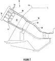
- Figure 1 shows a simplified cross-section of a combustor 10 according to one embodiment of the present invention.
- the combustor 10 may include one or more nozzles 12 radially arranged in a top cap 14.
- a casing 16 may surround the combustor 10 to contain the air or compressed working fluid exiting the compressor (not shown).
- An end cap 18 and a liner 20 generally surround a combustion chamber 22 downstream of the nozzles 12.
- a flow sleeve 24 with flow holes 26 may surround the liner 20 to define an annular passage 28 between the flow sleeve 24 and the liner 20.
- the compressed working fluid may pass through the flow holes 26 in the flow sleeve 24 to flow along the outside of the liner 20 to provide film or convective cooling to the liner 20.
- the compressed working fluid then reverses direction to flow through the one or more nozzles 12 and into the combustion chamber 22 where it mixes with fuel and ignites to produce combustion gases having a high temperature and pressure.
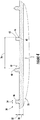
- Figures 2 and 3 show side plan views of the liner 20 according to first and second embodiments of the present invention.
- a ridge 30 on top of the liner 20 extends continuously around the circumference of the liner 20 to strengthen the liner 20.
- the ridge 30 may extend axially along a portion or the entire length of the liner 20, or a plurality of the ridges 30 may extend axially along some or all of the length of the liner 20.
- the ridge 30 may form a continuous substantially parallel spiral around the liner 20.
- the liner 20 may include a plurality of the ridges 30, with the ridges 30 forming substantially parallel circles or hoops around the circumference of the liner 20.
- Figure 4 provides an enlarged view of a portion of the liner 20 shown in Figure 2 or 3 .
- the ridge(s) 30 may be forged or cast with the liner 20 to facilitate ease of manufacturing, or the ridge(s) 30 may be added to the liner 20 by welding and subsequent machining, if desired.
- the dimensions and spacing of the ridge(s) 30 may be selected according to various design considerations to optimize the strength, stiffness, and/or rigidity of the liner 20, as well as the cooling provided by the ridge(s) 30.
- the height 32 and width 34 of the ridge(s) 30, as well as the distance 36 between adjacent ridge(s) 30 spiraling around or encircling the liner 20, may be selected based on the thickness 38 of the liner 20.
- the height 32 and/or width 34 of the ridge(s) 30 may be approximately 0.3-1.4 times the thickness 38 of the liner 20, and the distance 36 between adjacent ridges 30 may be approximately 8-45 times the thickness 38 of the liner 20.
- each ridge 30 may comprise a base 40 proximate to the liner 20 and a distal end 42.
- the base 40 may include a radius 44 along at least a portion of the base 40.
- the term "radius" includes any curved surface that reduces flow resistance across the outer surface of the liner 20.
- the length of the radius 44 may be selected based on the thickness 38 of the liner 20. For example, the radius 44 may have a curved length 49 of approximately .15-1 times the thickness 38 of the liner.
- the radius 44 may be forged or cast with the ridge(s) 30 during manufacture of the liner 20 or may be added separately, such as through lap welding and machining to produce a smooth, curved surface between the ridge(s) 30 and the liner 20.
- the distal end 42 may also include a radius 46 and/or terminate at a point 48 along at least a portion of the distal end 42.
- Figures 5 and 6 provide side plan views of the liner 20 according to third and fourth embodiments of the present invention.
- the ridge 30 again extends continuously around the circumference of the liner 20; however, the ridge 30 is substantially wider than in the embodiments shown in Figures 2-4 .
- the particular embodiments shown in Figures 5 and 6 further include a groove 50 that extends continuously around the liner 20 adjacent to the ridge 30.
- a radius 52 between the ridge 30 and the groove 50 provides a smooth transition between the ridge 30 and the groove 50.
- the ridge 30 and groove 50 may extend axially along a portion or the entire length of the liner 20, or a plurality of the ridges 30 and/or the grooves 50 may extend axially along some or all of the length of the liner 20. As shown in Figure 5 , the ridge 30 and groove 50 may form a continuous substantially parallel spiral around the liner 20. Alternately, as shown in the embodiment illustrated in Figure 6 , the liner 20 may include a plurality of the ridges 30 and grooves 50, with at least one groove 50 between adjacent ridges 30. In this manner, the ridges 30 and grooves 50 form substantially parallel circles or hoops around the circumference of the liner 20.
- Figure 7 provides an enlarged view of a portion of the liner 20 shown in Figure 5 or 6 .
- the ridge(s) 30, groove(s) 50, and radii 52 may be forged or cast with the liner 20 to facilitate ease of manufacturing, or the liner 20 may be pressed or stamped to form the ridge(s) 30, groove(s) 50, and radii 52, if desired.
- the dimensions and spacing of the ridge(s) 30, groove(s) 50, and radii 52 may be selected according to various design considerations to optimize the strength, stiffness, and/or rigidity of the liner 20, as well as the cooling provided by the ridge(s) 30 and groove(s) 50.
- the height 54 and width 56 of the ridge(s) 30 and/or the groove(s) 50 continuously spiraling around or encircling the liner 20 may be selected based on the thickness 38 of the liner 20.
- the height 54 of the ridge(s) 30 and/or groove(s) 50 may be approximately 1.1-2.5 times the thickness 38 of the liner 20
- the width 56 of the ridge(s) 30 and/or the groove(s) 50 may be approximately 8-45 times the thickness 38 of the liner 20 for liner thicknesses greater than approximately 0.09 inches and approximately 16-90 times the thickness 38 of the liner 20 for liner thicknesses less than approximately 0.09 inches.
- the radius 52 may have a curved length 58 of approximately 0.5-2.5 times the thickness 38 of the liner 20.
- the ridge(s) 30 and/or the groove(s) 50 may be substantially flat with the same height 54 and width 56, although such is not limitation of the present invention unless specifically recited in the claims.
- Figures 8 and 9 provide side plan views of the liner 20 according to fifth and sixth embodiments of the present invention.
- the ridge 30 again extends continuously around the circumference of the liner 20; however, the ridge 30 is curved with the convex surface facing outward.
- the particular embodiments shown in Figures 8 and 9 further include a groove 50 that extends continuously around the liner 20 adjacent to the ridge 30. A smooth transition between the ridge 30 and the groove 50 produces a wavy surface on the outside of the liner 20.
- the ridge 30 and groove 50 may extend axially along a portion or the entire length of the liner 20, or a plurality of the ridges 30 and/or the grooves 50 may extend axially along some or all of the length of the liner 20. As shown in Figure 8 , the ridge 30 and groove 50 may form a continuous substantially parallel spiral around the liner 20. Alternately, as shown in the embodiment illustrated in Figure 9 , the liner 20 may include a plurality of the ridges 30 and grooves 50, with at least one groove 50 between adjacent ridges 30. In this manner, the ridges 30 and grooves 50 form substantially parallel circles or hoops around the circumference of the liner 20.
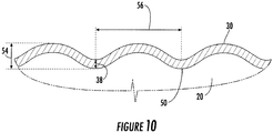
- Figure 10 provides an enlarged view of a portion of the liner 20 shown in Figure 8 or 9 .
- the ridge(s) 30 and groove(s) 50 may be forged or cast with the liner 20 to facilitate ease of manufacturing, or the liner 20 may be pressed or stamped to form the ridge(s) 30 and groove(s) 50, if desired.
- the dimensions and spacing of the ridge(s) 30 and groove(s) 50 may be selected according to various design considerations to optimize the strength, stiffness, and/or rigidity of the liner 20, as well as the cooling provided by the ridge(s) 30 and groove(s) 50.
- the height 54 and width 56 of the ridge(s) 30 and/or the groove(s) 50 continuously spiraling around or encircling the liner 20 may be selected based on the thickness 38 of the liner 20.
- the height 54 of the ridge(s) 30 and/or groove(s) 50 may be approximately 1.1-5 times the thickness 38 of the liner 20
- the width 56 of the ridge(s) 30 and/or groove(s) 50 may be approximately 8-45 times the thickness 38 of the liner 20 for liner thicknesses greater than approximately 0.09 inches and approximately 16-90 times the thickness 38 of the liner 20 for liner thicknesses less than approximately 0.09 inches.
- Figures 11 and 12 provide side plan views of the liner 20 according to seventh and eighth embodiments of the present invention.
- Each particular embodiment shown in Figures 11 and 12 may include a corrugated surface 60 with a radius 62 and a substantially flat segment 64 adjacent to the radius 62.
- the radius 62 and segment 64 extend continuously around the liner 20 to define an outer circumference of the liner 20.
- the segment 64 has a first end 66 and a second end 68, and the outer circumference of the liner 20 at the first end 66 is greater than the outer circumference of the liner 20 at the second end 68 to provide the corrugated surface 60.
- the direction of the corrugated surface 60 may vary according to particular embodiments. For example, in the embodiment shown in Figure 11 , the first end 66 is upstream from the second end 68, and in the embodiment shown in Figure 12 , the first and 66 is downstream from the second end 68.
- the radius 62 and segment 64 may extend axially along a portion or the entire length of the liner 20, or a plurality of the radii 62 and/or the segments 64 may extend axially along some or all of the length of the liner 20. As shown in Figure 11 , the radius 62 and the segment 64 may form a continuous substantially parallel spiral around the liner 20. Alternately, as shown in the embodiment illustrated in Figure 12 , the liner 20 may include a plurality of the continuous radii 62 and segments 64, with at least one segment 64 between adjacent radii 62. In this manner, the radii 62 and segments 64 form substantially parallel circles or hoops around the circumference of the liner 20.
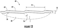
- Figure 13 provides an enlarged view of a portion of the liner 20 shown in Figure 11 or 12 .
- the radii 62 and segments 64 may be forged or cast with the liner 20 to facilitate ease of manufacturing, or the liner 20 may be pressed or stamped to form the radii 62 and segments 64, if desired.
- the dimensions and spacing of the radii 62 and segments 64 may be selected according to various design considerations to optimize the strength, stiffness, and/or rigidity of the liner 20, as well as the cooling provided by the radii 62 and segments 64.
- the slope 70 of the segments 64 may be approximately 2-8 degrees with respect to the axis of the liner 20.
- the height 72 of the corrugated surface 60 and the distance 74 between adjacent radii 62 or adjacent segments 64 continuously spiraling around or encircling the liner 20 may be selected based on the thickness 38 of the liner 20.
- the height 72 of the corrugated surface 60 may be approximately 1.1-3.0 times the thickness 38 of the liner 20.
- the distance 74 between adjacent radii 62 or adjacent segments 64 may be approximately 8-45 times the thickness 38 of the liner 20 for liner thicknesses greater than approximately 0.09 inches and approximately 16-90 times the thickness 38 of the liner 20 for liner thicknesses less than approximately 0.09 inches.
- the radii 62 may have a curved length 76 of approximately 0.5-2.5 times the thickness 38 of the liner 20.
Landscapes
- Engineering & Computer Science (AREA)
- Chemical & Material Sciences (AREA)
- Combustion & Propulsion (AREA)
- Mechanical Engineering (AREA)
- General Engineering & Computer Science (AREA)
- Cylinder Crankcases Of Internal Combustion Engines (AREA)
- Turbine Rotor Nozzle Sealing (AREA)
Applications Claiming Priority (1)
| Application Number | Priority Date | Filing Date | Title |
|---|---|---|---|
| US13/026,373 US20120208141A1 (en) | 2011-02-14 | 2011-02-14 | Combustor |
Publications (1)
| Publication Number | Publication Date |
|---|---|
| EP2487418A2 true EP2487418A2 (de) | 2012-08-15 |
Family
ID=45607042
Family Applications (1)
| Application Number | Title | Priority Date | Filing Date |
|---|---|---|---|
| EP12155001A Withdrawn EP2487418A2 (de) | 2011-02-14 | 2012-02-10 | Brennkammer |
Country Status (3)
| Country | Link |
|---|---|
| US (1) | US20120208141A1 (de) |
| EP (1) | EP2487418A2 (de) |
| CN (1) | CN102635876A (de) |
Cited By (2)
| Publication number | Priority date | Publication date | Assignee | Title |
|---|---|---|---|---|
| WO2015150098A1 (de) * | 2014-03-31 | 2015-10-08 | Siemens Aktiengesellschaft | Silobrennkammer für eine gasturbine |
| CN110657454A (zh) * | 2018-06-29 | 2020-01-07 | 中国航发商用航空发动机有限责任公司 | 一种冷却结构以及包括该冷却结构的燃烧室测量段 |
Families Citing this family (6)
| Publication number | Priority date | Publication date | Assignee | Title |
|---|---|---|---|---|
| US9511447B2 (en) * | 2013-12-12 | 2016-12-06 | General Electric Company | Process for making a turbulator by additive manufacturing |
| JP6066065B2 (ja) * | 2013-02-20 | 2017-01-25 | 三菱日立パワーシステムズ株式会社 | 伝熱装置を備えたガスタービン燃焼器 |
| US9989255B2 (en) * | 2014-07-25 | 2018-06-05 | General Electric Company | Liner assembly and method of turbulator fabrication |
| US20180001423A1 (en) * | 2016-07-01 | 2018-01-04 | General Electric Company | Methods and thin walled reinforced structures for additive manufacturing |
| CN108317542B (zh) * | 2018-01-03 | 2020-02-07 | 南方科技大学 | 航空发动机燃烧室的冷却结构及航空发动机燃烧室 |
| US11306918B2 (en) * | 2018-11-02 | 2022-04-19 | Chromalloy Gas Turbine Llc | Turbulator geometry for a combustion liner |
Family Cites Families (42)
| Publication number | Priority date | Publication date | Assignee | Title |
|---|---|---|---|---|
| US2728192A (en) * | 1945-06-20 | 1955-12-27 | Aerojet General Co | Combustion chamber for gas generation provided with cooling means and a system for operating the same |
| US3736747A (en) * | 1971-07-09 | 1973-06-05 | G Warren | Combustor |
| US4021191A (en) * | 1972-10-30 | 1977-05-03 | Aqua-Chem, Inc. | Reduction of pollutants in gaseous hydrocarbon combustion products |
| US4184326A (en) * | 1975-12-05 | 1980-01-22 | United Technologies Corporation | Louver construction for liner of gas turbine engine combustor |
| US4236378A (en) * | 1978-03-01 | 1980-12-02 | General Electric Company | Sectoral combustor for burning low-BTU fuel gas |
| US4292810A (en) * | 1979-02-01 | 1981-10-06 | Westinghouse Electric Corp. | Gas turbine combustion chamber |
| US4302940A (en) * | 1979-06-13 | 1981-12-01 | General Motors Corporation | Patterned porous laminated material |
| US4819438A (en) * | 1982-12-23 | 1989-04-11 | United States Of America | Steam cooled rich-burn combustor liner |
| EP0169431B1 (de) * | 1984-07-10 | 1990-04-11 | Hitachi, Ltd. | Brennkammer für eine Gasturbine |
| US5557932A (en) * | 1986-06-06 | 1996-09-24 | The United States Of America As Represented By The Secretary Of The Air Force | Low thermal stress impingement cooling apparatus |
| US4787209A (en) * | 1987-04-29 | 1988-11-29 | Avco Corporation | Stacked ring combustor assembly |
| US5181379A (en) * | 1990-11-15 | 1993-01-26 | General Electric Company | Gas turbine engine multi-hole film cooled combustor liner and method of manufacture |
| US5233828A (en) * | 1990-11-15 | 1993-08-10 | General Electric Company | Combustor liner with circumferentially angled film cooling holes |
| CA2056592A1 (en) * | 1990-12-21 | 1992-06-22 | Phillip D. Napoli | Multi-hole film cooled combustor liner with slotted film starter |
| GB9127505D0 (en) * | 1991-03-11 | 2013-12-25 | Gen Electric | Multi-hole film cooled afterburner combustor liner |
| US5181377A (en) * | 1991-04-16 | 1993-01-26 | General Electric Company | Damped combustor cowl structure |
| US5201847A (en) * | 1991-11-21 | 1993-04-13 | Westinghouse Electric Corp. | Shroud design |
| US5207570A (en) * | 1992-02-26 | 1993-05-04 | Voorheis Industries, Inc. | Bluff body band register and bluff body band pilot |
| JPH08278029A (ja) * | 1995-02-06 | 1996-10-22 | Toshiba Corp | 燃焼器用ライナー及びその製造方法 |
| JPH09133362A (ja) * | 1995-11-06 | 1997-05-20 | Mitsubishi Heavy Ind Ltd | ガスタービン燃焼器の冷却構造 |
| JPH09196377A (ja) * | 1996-01-12 | 1997-07-29 | Hitachi Ltd | ガスタービン燃焼器 |
| US5724816A (en) * | 1996-04-10 | 1998-03-10 | General Electric Company | Combustor for a gas turbine with cooling structure |
| GB9623615D0 (en) * | 1996-11-13 | 1997-07-09 | Rolls Royce Plc | Jet pipe liner |
| GB2328011A (en) * | 1997-08-05 | 1999-02-10 | Europ Gas Turbines Ltd | Combustor for gas or liquid fuelled turbine |
| GB2359882B (en) * | 2000-02-29 | 2004-01-07 | Rolls Royce Plc | Wall elements for gas turbine engine combustors |
| US6760972B2 (en) * | 2000-09-21 | 2004-07-13 | Packless Metal Hose, Inc. | Apparatus and methods for forming internally and externally textured tubing |
| US6526756B2 (en) * | 2001-02-14 | 2003-03-04 | General Electric Company | Method and apparatus for enhancing heat transfer in a combustor liner for a gas turbine |
| US6530225B1 (en) * | 2001-09-21 | 2003-03-11 | Honeywell International, Inc. | Waffle cooling |
| ITMI20012785A1 (it) * | 2001-12-21 | 2003-06-21 | Nuovo Pignone Spa | Tubo di fianna o "liner" migliorato per una camera di combustione di una turbina a gas a basse emissioni inquinanti |
| US6655147B2 (en) * | 2002-04-10 | 2003-12-02 | General Electric Company | Annular one-piece corrugated liner for combustor of a gas turbine engine |
| US7104067B2 (en) * | 2002-10-24 | 2006-09-12 | General Electric Company | Combustor liner with inverted turbulators |
| US7269957B2 (en) * | 2004-05-28 | 2007-09-18 | Martling Vincent C | Combustion liner having improved cooling and sealing |
| SE527732C2 (sv) * | 2004-10-07 | 2006-05-23 | Volvo Aero Corp | Ett hölje för omslutande av en gasturbinkomponent |
| US7386980B2 (en) * | 2005-02-02 | 2008-06-17 | Power Systems Mfg., Llc | Combustion liner with enhanced heat transfer |
| US7540156B2 (en) * | 2005-11-21 | 2009-06-02 | General Electric Company | Combustion liner for gas turbine formed of cast nickel-based superalloy |
| EP2267369A4 (de) * | 2008-03-31 | 2014-11-26 | Kawasaki Heavy Ind Ltd | Kühlstruktur für gasturbinenbrennkammer |
| US8056343B2 (en) * | 2008-10-01 | 2011-11-15 | General Electric Company | Off center combustor liner |
| US20100186415A1 (en) * | 2009-01-23 | 2010-07-29 | General Electric Company | Turbulated aft-end liner assembly and related cooling method |
| US20100205972A1 (en) * | 2009-02-17 | 2010-08-19 | General Electric Company | One-piece can combustor with heat transfer surface enhacements |
| US8516822B2 (en) * | 2010-03-02 | 2013-08-27 | General Electric Company | Angled vanes in combustor flow sleeve |
| US20110239654A1 (en) * | 2010-04-06 | 2011-10-06 | Gas Turbine Efficiency Sweden Ab | Angled seal cooling system |
| US8201412B2 (en) * | 2010-09-13 | 2012-06-19 | General Electric Company | Apparatus and method for cooling a combustor |
-
2011
- 2011-02-14 US US13/026,373 patent/US20120208141A1/en not_active Abandoned
-
2012
- 2012-02-10 EP EP12155001A patent/EP2487418A2/de not_active Withdrawn
- 2012-02-14 CN CN2012100405136A patent/CN102635876A/zh active Pending
Non-Patent Citations (1)
| Title |
|---|
| None |
Cited By (2)
| Publication number | Priority date | Publication date | Assignee | Title |
|---|---|---|---|---|
| WO2015150098A1 (de) * | 2014-03-31 | 2015-10-08 | Siemens Aktiengesellschaft | Silobrennkammer für eine gasturbine |
| CN110657454A (zh) * | 2018-06-29 | 2020-01-07 | 中国航发商用航空发动机有限责任公司 | 一种冷却结构以及包括该冷却结构的燃烧室测量段 |
Also Published As
| Publication number | Publication date |
|---|---|
| US20120208141A1 (en) | 2012-08-16 |
| CN102635876A (zh) | 2012-08-15 |
Similar Documents
| Publication | Publication Date | Title |
|---|---|---|
| EP2487418A2 (de) | Brennkammer | |
| US8171736B2 (en) | Combustor with chamfered dome | |
| EP2481983B1 (de) | Turbulenz erzeugende Hinterkantenverkleidungsanordnung und Kühlungsverfahren für Gasturbinenbrennkammer | |
| EP1353127B1 (de) | Einteilige ringförmige Verkleidung für Gasturbinenbrennkammer | |
| US9316396B2 (en) | Hot gas path duct for a combustor of a gas turbine | |
| US20140033718A1 (en) | Combustor | |
| EP2636952A2 (de) | Kraftstoffdüse und Brennkammer für eine Gasturbine | |
| EP2679775A1 (de) | Überleitkanal für eine Gasturbine | |
| EP3189215B1 (de) | Dichtungsanordnung am übergang zu einer turbine | |
| EP2860353A1 (de) | Gasturbinenbrennkammer | |
| EP2532962A2 (de) | Brennermantel mit Turbulatoren | |
| US8196412B2 (en) | Gas turbine transition duct profile | |
| EP2957832B1 (de) | Wärmeleitende vorrichtung und gasturbinenbrennkammer damit | |
| EP2538027A2 (de) | Verfahren und Systeme zur Übertragung von Wärme aus einem Übergangskanal | |
| US9366438B2 (en) | Flow sleeve inlet assembly in a gas turbine engine | |
| US9145778B2 (en) | Combustor with non-circular head end | |
| CN108626751B (zh) | 火焰筒 | |
| EP1966539B1 (de) | Federbügeldichtung für eine turbine | |
| EP2532836A2 (de) | Brennermantel und Übergangsstück | |
| US12595910B2 (en) | Combustion liner | |
| JP2002295268A (ja) | ガスタービン燃焼器ライナー構造とその補修方法 | |
| EP2578937A2 (de) | Brennermantelanordnung mit Filmkühlung | |
| US9528392B2 (en) | System for supporting a turbine nozzle | |
| US20190101287A1 (en) | Cooling structure for gas turbine engine | |
| EP2573465A2 (de) | Brennkammer und Verfahren zur Konditionierung der Strömung durch eine Brennkammer |
Legal Events
| Date | Code | Title | Description |
|---|---|---|---|
| PUAI | Public reference made under article 153(3) epc to a published international application that has entered the european phase |
Free format text: ORIGINAL CODE: 0009012 |
|
| AK | Designated contracting states |
Kind code of ref document: A2 Designated state(s): AL AT BE BG CH CY CZ DE DK EE ES FI FR GB GR HR HU IE IS IT LI LT LU LV MC MK MT NL NO PL PT RO RS SE SI SK SM TR |
|
| AX | Request for extension of the european patent |
Extension state: BA ME |
|
| STAA | Information on the status of an ep patent application or granted ep patent |
Free format text: STATUS: THE APPLICATION IS DEEMED TO BE WITHDRAWN |
|
| 18D | Application deemed to be withdrawn |
Effective date: 20150901 |