EP2500184A1 - Agencement d'axe rigide dans un véhicule, notamment dans un véhicule utilitaire - Google Patents
Agencement d'axe rigide dans un véhicule, notamment dans un véhicule utilitaire Download PDFInfo
- Publication number
- EP2500184A1 EP2500184A1 EP11009878A EP11009878A EP2500184A1 EP 2500184 A1 EP2500184 A1 EP 2500184A1 EP 11009878 A EP11009878 A EP 11009878A EP 11009878 A EP11009878 A EP 11009878A EP 2500184 A1 EP2500184 A1 EP 2500184A1
- Authority
- EP
- European Patent Office
- Prior art keywords
- axle body
- axle
- console
- region
- vehicle
- Prior art date
- Legal status (The legal status is an assumption and is not a legal conclusion. Google has not performed a legal analysis and makes no representation as to the accuracy of the status listed.)
- Granted
Links
Images
Classifications
-
- B—PERFORMING OPERATIONS; TRANSPORTING
- B60—VEHICLES IN GENERAL
- B60B—VEHICLE WHEELS; CASTORS; AXLES FOR WHEELS OR CASTORS; INCREASING WHEEL ADHESION
- B60B35/00—Axle units; Parts thereof ; Arrangements for lubrication of axles
- B60B35/004—Mounting arrangements for axles
- B60B35/006—Mounting arrangements for axles with mounting plates or consoles fitted to axles
- B60B35/007—Mounting arrangements for axles with mounting plates or consoles fitted to axles for mounting suspension elements to axles
-
- B—PERFORMING OPERATIONS; TRANSPORTING
- B60—VEHICLES IN GENERAL
- B60B—VEHICLE WHEELS; CASTORS; AXLES FOR WHEELS OR CASTORS; INCREASING WHEEL ADHESION
- B60B35/00—Axle units; Parts thereof ; Arrangements for lubrication of axles
- B60B35/02—Dead axles, i.e. not transmitting torque
- B60B35/06—Dead axles, i.e. not transmitting torque cranked
-
- B—PERFORMING OPERATIONS; TRANSPORTING
- B60—VEHICLES IN GENERAL
- B60G—VEHICLE SUSPENSION ARRANGEMENTS
- B60G9/00—Resilient suspensions of a rigid axle or axle housing for two or more wheels
-
- B—PERFORMING OPERATIONS; TRANSPORTING
- B60—VEHICLES IN GENERAL
- B60B—VEHICLE WHEELS; CASTORS; AXLES FOR WHEELS OR CASTORS; INCREASING WHEEL ADHESION
- B60B2310/00—Manufacturing methods
- B60B2310/30—Manufacturing methods joining
- B60B2310/305—Manufacturing methods joining by screwing
-
- B—PERFORMING OPERATIONS; TRANSPORTING
- B60—VEHICLES IN GENERAL
- B60B—VEHICLE WHEELS; CASTORS; AXLES FOR WHEELS OR CASTORS; INCREASING WHEEL ADHESION
- B60B2360/00—Materials; Physical forms thereof
- B60B2360/10—Metallic materials
- B60B2360/102—Steel
-
- B—PERFORMING OPERATIONS; TRANSPORTING
- B60—VEHICLES IN GENERAL
- B60B—VEHICLE WHEELS; CASTORS; AXLES FOR WHEELS OR CASTORS; INCREASING WHEEL ADHESION
- B60B2900/00—Purpose of invention
- B60B2900/30—Increase in
- B60B2900/321—Lifetime
-
- B—PERFORMING OPERATIONS; TRANSPORTING
- B60—VEHICLES IN GENERAL
- B60G—VEHICLE SUSPENSION ARRANGEMENTS
- B60G2200/00—Indexing codes relating to suspension types
- B60G2200/30—Rigid axle suspensions
- B60G2200/314—Rigid axle suspensions with longitudinally arranged arms articulated on the axle
- B60G2200/315—Rigid axle suspensions with longitudinally arranged arms articulated on the axle at least one of the arms having an A or V shape
-
- B—PERFORMING OPERATIONS; TRANSPORTING
- B60—VEHICLES IN GENERAL
- B60G—VEHICLE SUSPENSION ARRANGEMENTS
- B60G2200/00—Indexing codes relating to suspension types
- B60G2200/30—Rigid axle suspensions
- B60G2200/34—Stabilising mechanisms, e.g. for lateral stability
- B60G2200/343—Stabilising mechanisms, e.g. for lateral stability with an axle suspended by two pivoted rods in "V"-arrangement, the rods being coupled at its apex
-
- B—PERFORMING OPERATIONS; TRANSPORTING
- B60—VEHICLES IN GENERAL
- B60G—VEHICLE SUSPENSION ARRANGEMENTS
- B60G2200/00—Indexing codes relating to suspension types
- B60G2200/40—Indexing codes relating to the wheels in the suspensions
- B60G2200/42—Driven wheels or dead axles
-
- B—PERFORMING OPERATIONS; TRANSPORTING
- B60—VEHICLES IN GENERAL
- B60Y—INDEXING SCHEME RELATING TO ASPECTS CROSS-CUTTING VEHICLE TECHNOLOGY
- B60Y2200/00—Type of vehicle
- B60Y2200/10—Road Vehicles
- B60Y2200/14—Trucks; Load vehicles, Busses
- B60Y2200/142—Heavy duty trucks
Definitions
- the invention relates to a rigid axle arrangement in a vehicle, in particular in a commercial vehicle, according to the preamble of claim 1.
- axle body of a vehicle in particular as a liftable leading or trailing axle of a truck or bus, known.
- the axle body of this rigid axle is bulged down here in its middle part and is crossed in this area by a drive shaft leading to an adjacent axis at a distance.
- the axle body is hinged on lower side members and an upper wishbone on the chassis frame of the vehicle and supported by springs and dampers against the latter.
- the axle body is constructed and consists of three prefabricated parts, namely of a forged or molded, formed in the manner of a yoke center part and two side pieces formed by pieces of pipe, which are welded to the ends of the central part.
- the attachment bracket serving for fastening the wishbone protrudes upwards from the axle body and is connected to it in a lateral middle part, offset to the longitudinal center plane or to the longitudinal center region of the axle body.
- the drive shaft extends laterally offset to this attachment bracket approximately in a longitudinal center region of the axle body.
- a rigid axle arrangement in a vehicle, in particular in a commercial vehicle, with a rigid axle having an axle body extending in the vehicle transverse direction, from which a mounting bracket for a multi-point link protrudes upward, the multi-point link with its handlebars on the one hand, seen in a vehicle vertical axis direction , spaced above the axle body lying console-side multi-point link connecting portion of the mounting bracket and on the other hand to a frame of the vehicle directly or indirectly hinged.
- the console-side multi-point link connection region is arranged at a distance above a longitudinal center region of the axle body relative to the longitudinal extension direction of the axle body, whereby at least one console arm is guided downwards from the console-side multipoint link connection region to the axle body and abuts on opposite sides of the longitudinal center region of the axle body this is connected.
- the longitudinal center region is preferably defined here by a center axis which divides the axle body into approximately two axle body halves of equal length.
- the console-side multi-point linkage connection area is located above the longitudinal center region of the axle body, from which several console arms are guided downwards to the axle body, the introduction of force can preferably take place essentially symmetrically and via the plurality of console arms in one desired way the power flow are divided into the axle body.
- the console arms can be constructed as a whole slimmer and with smaller dimensions, as in a one-arm mounting bracket according to the generic state of the art DE 103 33 760 A1 the case is.
- a further significant advantage of the solution according to the invention lies in the fact that a construction in which the longitudinal middle region-side region above the axle body remains unobstructed can be created by this longitudinal middle region-side or longitudinal mid-plane arrangement of the console-side multi-point linkage region together with the console arms guided downward by these here considerable constructive degrees of freedom in conjunction with an arrangement of a drive to a drive axle of the vehicle, in particular to one of the rigid axle adjacent drive axle of the vehicle, guided and the rigid axle or the axle body crossing drive shaft yield. Accordingly, a free space is thus formed in the region between the console arms and the axle body, in which a running in the vehicle longitudinal direction and the axle body transverse drive shaft of the vehicle is arranged.
- the mounting bracket has a U- or V-shape with arranged in the region of the U or V base and / or trained multipoint linkage connection area, starting from which base the U or V-leg training console arms are guided downward to the axle body, that the mounting bracket and the axle body surround the space for the arrangement of the drive shaft annular.
- the console arms can thus be guided toward the axle body in the direction away from the central axis or from the longitudinal center region to the axle body, in order to form the largest possible space for arranging the drive shaft.
- This clearance for the arrangement of the drive shaft can additionally be increased by the fact that the console arms are curved away from the center axis or from the longitudinal center region of the axle body to the outside.
- the axle body may also be provided with a bulge area in an axle body middle part having the longitudinal center region, preferably being bulged downwards in vehicle vertical axis direction, the axle body being provided with an axle body transition region adjoining on both sides of the bulge area. in particular with an oblique or curved with respect to the vehicle vertical axis direction and the vehicle transverse direction extending axle body transition region, merges into the axle body side panels.
- console arms starting from the multi-point linkage connection area, are guided obliquely outward from the longitudinal center region of the axle body to the axle body, preferably in such a way that the bracket arms on the opposite sides of the longitudinal center area in FIG Axle body transition region from the axle body middle part are connected to the axle body side panels.
- a connection in the region of the axle body transition region in the vehicle transverse direction to the outside subsequent axle body side parts is basically possible and conceivable.
- the mounting bracket itself may be formed in one or more parts, wherein the mounting bracket is preferably formed by a one-piece or multi-part formed sheet metal component, which also has a high strength in addition to ease of manufacture.
- the attachment bracket is thus preferably formed by a separate component, which is connected to the axle body by means of at least one fastening means, in particular material and / or non-positively and / or positively connected.
- console arms follow with their achs phenomenon desken connection areas, in particular with their free ends, at least in partial areas of the shaping and / or the contour of Achsterrorism transition areas and abut there in a planar contact connection and are connected.
- console arms here from the multipoint link area Starting so from the longitudinal center region away out to be adjacent to the axle body side portions of the respective Achs stresses- transition area or possibly also guided to the axle body side parts, that the space for the arrangement of the drive shaft above the axle body is formed as large as possible during the free ends of the console arms, which bear on the axle body, for example on the axle body transition region, may then again be bent in the region outside the free space such that they follow the axle body in a planar contact connection, for example following the axle body transition region in the direction of the longitudinal center, This means that they can thus be bent, for example, back towards the longitudinal center region of the axle body, because this has no effect on the free space training.
- the console-side multi-point link connecting region may be formed integrally with the attachment bracket or be formed by a separate component which is fixedly connected to the console arms, in particular material and / or non-positively and / or positively connected. Again, with the formation of the multi-point linkage area by a separate component constructive freedoms arise, although the integral solution is basically possible and possibly reduces the assembly effort.
- the console-side multi-point linkage connection area has at least one connection element, in particular at least one connection claw, for at least one linkage bearing, in particular an elastomeric metal bearing, and / or carries.
- Particularly preferred here is a concrete structure in which the console-side multi-point link connecting region has a plate-like carrier region, on which the at least one connection element, in particular the at least one connection claw, is arranged, wherein the console arms originate from the carrier plate and are firmly connected thereto.
- a plate-like support area on the one hand results in an advantageous functionally reliable connection possibility of the console arms and also a simple arrangement possibility of at least one arm bearing or connecting element.
- the console-side multi-point link connection region is preferably formed so that the only Handlebar connection point in the longitudinal center region of the mounting bracket is located.
- the console-side multi-point link connection region is preferably designed such that the two console-side link attachment points are arranged substantially symmetrically with respect to the longitudinal center region of the axle body.
- This axle beam is preferably a built axle body, in which the axle body-Mitteilteil having the Achs stresses transition areas is made as a separate component and is connected to the axle body side parts also produced by separate components.
- the rigid axle may be, for example, a leading axle upstream of a drive axle or a trailing axle of a commercial vehicle, in particular a heavy goods vehicle or a bus, arranged downstream of a drive axle.
- the rigid axle can also be designed as a lift axle, which may then be arranged on the mounting bracket, if necessary, even more components for raising and lowering the rigid axle.
- the invention further relates to a mounting bracket for a rigid axle assembly according to one of the preceding claims with a multi-point link connecting region having mounting bracket, protrude from the more console arms.
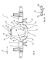
- FIG. 1a shows a rigid axle 1 with a built axle body 2, which has an axle body middle part 3 and attached thereto, in particular welded or flanged axle body side parts 4, 5.
- the individual axle body components can according to the embodiment of DE 103 33 760 A1 be educated.
- the axle body 2 is provided in the region of the axle body middle part 3 with a bulge region 6, the bulge 7 being directed downwards in the vehicle vertical axis direction z.
- the bulge region 6 of the axle body middle part 3 extends approximately horizontally on both sides of the longitudinal center region 9 of the axle body 2 defined by the center axis 8 and thus extends substantially in the vehicle transverse axis direction y.
- this bulge region 6 close to obliquely or curved with respect to the vehicle vertical axis direction z and the vehicle transverse direction y extending Achs emotions transition areas 10, 11, on both sides of the longitudinal center region 9, which Achs stresses transition areas 10 in the side parts 3, 4 pass ,
- a multipoint link connection region 12 of a mounting bracket 13 is arranged at a distance above the longitudinal center region 9 of the axle body middle part 3 defined by the central axis 8.
- This multipoint link connection region 12 is formed here by way of example by a carrier plate 14 carrying a connection claw 15, the connection claw 15 being arranged symmetrically with respect to the center axis 8 with respect to its connection points 16, 17, so that the center axis 8 is exactly through the longitudinal center of the multipoint linkage region 12 runs.
- the multipoint link connection area may have two connection claws 15a, 15b ( FIG. 1b ), which is analogous to the embodiment according to FIG. 1a are arranged symmetrically with respect to the central axis 8, to allow a symmetrical force application.
- the attached to the support plate 14, for example, welded console arms are in the FIG. 1b for clarity not shown.
- the support plate 14 of the multi-point linkage region which is arranged at a distance above the longitudinal center region 9 of the axle body 2 of the rigid axle 1, is further firmly connected, for example welded, to two bracket arms 18, 19, which console arms 18, 19 likewise form part of the attachment bracket 13 according to the invention .
- the console arms 18, 19, again in relation to the center axis 8 or the longitudinal center region 9 of the axle body 2, are designed as substantially symmetrical identical parts, which comprise a first subregion 20 extending above the axle body 2 from the longitudinal center region 9 or the center axis 8 away obliquely outward to the axle body transitional areas 10, 11 are guided, where the console arms 18, 19 with a second portion 21, which adjoins the first portion 20, in turn are bent inwardly toward the longitudinal center region 9 of the axle body 2 and the course of the axle body transition region 10 and 11 follow so that they rest there in a planar contact connection.
- the two console arms 18, 19 are finally fixed in the region of the axle body transition regions 10, 11 by means of a plurality of, for
Landscapes
- Engineering & Computer Science (AREA)
- Mechanical Engineering (AREA)
- Vehicle Body Suspensions (AREA)
- Forklifts And Lifting Vehicles (AREA)
Applications Claiming Priority (1)
| Application Number | Priority Date | Filing Date | Title |
|---|---|---|---|
| DE102011014106A DE102011014106A1 (de) | 2011-03-16 | 2011-03-16 | Starrachsenanordnung in einem Fahrzeug, insbesondere in einem Nutzfahrzeug |
Publications (2)
| Publication Number | Publication Date |
|---|---|
| EP2500184A1 true EP2500184A1 (fr) | 2012-09-19 |
| EP2500184B1 EP2500184B1 (fr) | 2015-03-18 |
Family
ID=45421787
Family Applications (1)
| Application Number | Title | Priority Date | Filing Date |
|---|---|---|---|
| EP11009878.7A Active EP2500184B1 (fr) | 2011-03-16 | 2011-12-15 | Agencement d'axe rigide dans un véhicule, notamment dans un véhicule utilitaire |
Country Status (5)
| Country | Link |
|---|---|
| EP (1) | EP2500184B1 (fr) |
| CN (1) | CN102700364B (fr) |
| BR (1) | BR102012005756B1 (fr) |
| DE (1) | DE102011014106A1 (fr) |
| EA (1) | EA025963B1 (fr) |
Cited By (3)
| Publication number | Priority date | Publication date | Assignee | Title |
|---|---|---|---|---|
| WO2014161084A1 (fr) * | 2013-04-05 | 2014-10-09 | Mth Manufacturing Inc. | Essieu concave mécanosoudé et son procédé de fabrication |
| US9731551B2 (en) | 2013-04-05 | 2017-08-15 | Mth Manufacturing Inc. | Fabricated drop axle and method of manufacturing same |
| CN110325382A (zh) * | 2016-10-18 | 2019-10-11 | 塞夫-霍兰德公司 | 车辆悬架布置 |
Families Citing this family (1)
| Publication number | Priority date | Publication date | Assignee | Title |
|---|---|---|---|---|
| DE102016102133A1 (de) * | 2016-02-08 | 2017-08-10 | Saf-Holland Gmbh | Achseinheit |
Citations (7)
| Publication number | Priority date | Publication date | Assignee | Title |
|---|---|---|---|---|
| JPS62194975A (ja) * | 1986-02-20 | 1987-08-27 | Hino Motors Ltd | 自動車の後軸操舵装置 |
| DE3725102A1 (de) * | 1987-07-29 | 1989-02-16 | Brueninghaus Krupp Gmbh | Dreieckslenker eines fahrzeugs |
| WO1997047484A1 (fr) * | 1996-06-11 | 1997-12-18 | The Boler Company | Organe de commande reglable pour chassis et essieux de vehicule |
| EP0914976A1 (fr) * | 1997-05-26 | 1999-05-12 | Isuzu Motors Limited | Suspension pour vehicules |
| DE19920670A1 (de) * | 1999-05-05 | 2000-11-23 | Man Nutzfahrzeuge Ag | Achskörper einer Vorlauf-, Nachlauf- oder Liftachse für Nutzfahrzeuge |
| EP1120299A1 (fr) * | 2000-01-25 | 2001-08-01 | Hino Motors, Ltd. | Structure de montage pour un triangle de suspension |
| DE10333760A1 (de) | 2003-07-24 | 2005-02-17 | Man Nutzfahrzeuge Ag | Starrachse eines Fahrzeugs, insbesondere liftbare Vor- oder Nachlaufachse eines Lastkraftwagens oder Omnibusse |
Family Cites Families (3)
| Publication number | Priority date | Publication date | Assignee | Title |
|---|---|---|---|---|
| FI100178B (fi) * | 1995-09-29 | 1997-10-15 | Tamrock Oy | Akselistorakenne ajoneuvoa varten |
| IT1314127B1 (it) * | 1999-12-14 | 2002-12-04 | Dana Italia Spa | Assale rigido sospeso. |
| DE102009017287A1 (de) * | 2009-04-11 | 2010-10-14 | Man Nutzfahrzeuge Ag | Achskonstruktion für ein Fahrzeug, insbesondere für ein Nutzfahrzeug |
-
2011
- 2011-03-16 DE DE102011014106A patent/DE102011014106A1/de not_active Withdrawn
- 2011-12-15 EP EP11009878.7A patent/EP2500184B1/fr active Active
-
2012
- 2012-02-08 EA EA201200107A patent/EA025963B1/ru not_active IP Right Cessation
- 2012-03-14 BR BR102012005756-5A patent/BR102012005756B1/pt active IP Right Grant
- 2012-03-16 CN CN201210082724.6A patent/CN102700364B/zh active Active
Patent Citations (7)
| Publication number | Priority date | Publication date | Assignee | Title |
|---|---|---|---|---|
| JPS62194975A (ja) * | 1986-02-20 | 1987-08-27 | Hino Motors Ltd | 自動車の後軸操舵装置 |
| DE3725102A1 (de) * | 1987-07-29 | 1989-02-16 | Brueninghaus Krupp Gmbh | Dreieckslenker eines fahrzeugs |
| WO1997047484A1 (fr) * | 1996-06-11 | 1997-12-18 | The Boler Company | Organe de commande reglable pour chassis et essieux de vehicule |
| EP0914976A1 (fr) * | 1997-05-26 | 1999-05-12 | Isuzu Motors Limited | Suspension pour vehicules |
| DE19920670A1 (de) * | 1999-05-05 | 2000-11-23 | Man Nutzfahrzeuge Ag | Achskörper einer Vorlauf-, Nachlauf- oder Liftachse für Nutzfahrzeuge |
| EP1120299A1 (fr) * | 2000-01-25 | 2001-08-01 | Hino Motors, Ltd. | Structure de montage pour un triangle de suspension |
| DE10333760A1 (de) | 2003-07-24 | 2005-02-17 | Man Nutzfahrzeuge Ag | Starrachse eines Fahrzeugs, insbesondere liftbare Vor- oder Nachlaufachse eines Lastkraftwagens oder Omnibusse |
Cited By (5)
| Publication number | Priority date | Publication date | Assignee | Title |
|---|---|---|---|---|
| WO2014161084A1 (fr) * | 2013-04-05 | 2014-10-09 | Mth Manufacturing Inc. | Essieu concave mécanosoudé et son procédé de fabrication |
| US9731551B2 (en) | 2013-04-05 | 2017-08-15 | Mth Manufacturing Inc. | Fabricated drop axle and method of manufacturing same |
| CN110325382A (zh) * | 2016-10-18 | 2019-10-11 | 塞夫-霍兰德公司 | 车辆悬架布置 |
| US11192418B2 (en) * | 2016-10-18 | 2021-12-07 | Saf-Holland, Inc. | Vehicle suspension arrangement |
| CN110325382B (zh) * | 2016-10-18 | 2022-12-09 | 塞夫-霍兰德公司 | 车辆悬架布置 |
Also Published As
| Publication number | Publication date |
|---|---|
| EA201200107A1 (ru) | 2012-10-30 |
| DE102011014106A1 (de) | 2012-09-20 |
| EP2500184B1 (fr) | 2015-03-18 |
| CN102700364A (zh) | 2012-10-03 |
| BR102012005756A2 (pt) | 2013-11-05 |
| BR102012005756B1 (pt) | 2020-06-23 |
| EA025963B1 (ru) | 2017-02-28 |
| CN102700364B (zh) | 2016-03-30 |
Similar Documents
| Publication | Publication Date | Title |
|---|---|---|
| DE102013108695B4 (de) | Hilfsrahmen für eine Kraftfahrzeugachse | |
| EP2355988B1 (fr) | Suspension d'essieu pour un essieu de véhicule | |
| EP2637913B1 (fr) | Agencement de traverses, en particulier de traverses de plancher et/ou agencement de traverses d'espace-pieds dans une carrosserie de véhicule, en particulier dans une carrosserie de véhicule automobile | |
| EP4001022B1 (fr) | Agencement de pare-chocs | |
| DE102014100618B3 (de) | Kraftfahrzeugachse | |
| EP3192680B1 (fr) | Ensemble d'essieu pour un véhicule | |
| EP2500184B1 (fr) | Agencement d'axe rigide dans un véhicule, notamment dans un véhicule utilitaire | |
| DE102010006669B4 (de) | Profilknoten für eine Fahrzeugkarosserie | |
| DE102013107179B4 (de) | Stoßabsorptionsvorrichtung für ein Kraftfahrzeug | |
| EP3498504B1 (fr) | Bras de suspension à ressort pour une suspension de roue d'un véhicule automobile | |
| DE102010044055B4 (de) | Fahrzeugsitzgestell | |
| EP2308744B1 (fr) | Véhicule utilitaire avec cadre de châssis doté d'un membre transversal ajustable en position et scindé | |
| EP2766245A1 (fr) | Châssis auxiliaire pour véhicules automobiles | |
| DE102014223054A1 (de) | Fahrzeugkarosserie für ein Fahrzeug | |
| EP2986459B1 (fr) | Bras oscillant longitudinal | |
| DE102015100225B4 (de) | Wasserkastenanordnung für einen Personenkraftwagen | |
| DE102011010201A1 (de) | Schlussquerträger für ein Nutzfahrzeug | |
| DE102009051039B4 (de) | Gussteil für eine Karosserie eines Kraftfahrzeugs | |
| EP3501952B1 (fr) | Compensation de la tolérance des éléments de montage dans des modules au moyen des éléments élastiques | |
| EP2969891B1 (fr) | Chassis de levage pour chariot de manutention | |
| DE102013203856A1 (de) | Querlenker für ein Fahrzeug | |
| DE102006021149A1 (de) | Rahmeneinlage | |
| EP4400394A1 (fr) | Véhicule doté d'une structure montée de manière mobile | |
| EP1871630A1 (fr) | Systeme de gaz d'echappement a deux voies | |
| DE102013000480A1 (de) | Hilfsrahmenkonsole zur Anbindung eines radführenden Lenkers |
Legal Events
| Date | Code | Title | Description |
|---|---|---|---|
| PUAI | Public reference made under article 153(3) epc to a published international application that has entered the european phase |
Free format text: ORIGINAL CODE: 0009012 |
|
| 17P | Request for examination filed |
Effective date: 20120619 |
|
| AK | Designated contracting states |
Kind code of ref document: A1 Designated state(s): AL AT BE BG CH CY CZ DE DK EE ES FI FR GB GR HR HU IE IS IT LI LT LU LV MC MK MT NL NO PL PT RO RS SE SI SK SM TR |
|
| AX | Request for extension of the european patent |
Extension state: BA ME |
|
| GRAP | Despatch of communication of intention to grant a patent |
Free format text: ORIGINAL CODE: EPIDOSNIGR1 |
|
| INTG | Intention to grant announced |
Effective date: 20141202 |
|
| GRAS | Grant fee paid |
Free format text: ORIGINAL CODE: EPIDOSNIGR3 |
|
| GRAA | (expected) grant |
Free format text: ORIGINAL CODE: 0009210 |
|
| AK | Designated contracting states |
Kind code of ref document: B1 Designated state(s): AL AT BE BG CH CY CZ DE DK EE ES FI FR GB GR HR HU IE IS IT LI LT LU LV MC MK MT NL NO PL PT RO RS SE SI SK SM TR |
|
| REG | Reference to a national code |
Ref country code: GB Ref legal event code: FG4D Free format text: NOT ENGLISH |
|
| REG | Reference to a national code |
Ref country code: CH Ref legal event code: EP |
|
| REG | Reference to a national code |
Ref country code: IE Ref legal event code: FG4D Free format text: LANGUAGE OF EP DOCUMENT: GERMAN |
|
| REG | Reference to a national code |
Ref country code: AT Ref legal event code: REF Ref document number: 716315 Country of ref document: AT Kind code of ref document: T Effective date: 20150415 |
|
| REG | Reference to a national code |
Ref country code: DE Ref legal event code: R096 Ref document number: 502011006252 Country of ref document: DE Effective date: 20150430 |
|
| REG | Reference to a national code |
Ref country code: SE Ref legal event code: TRGR |
|
| REG | Reference to a national code |
Ref country code: NL Ref legal event code: T3 |
|
| PG25 | Lapsed in a contracting state [announced via postgrant information from national office to epo] |
Ref country code: FI Free format text: LAPSE BECAUSE OF FAILURE TO SUBMIT A TRANSLATION OF THE DESCRIPTION OR TO PAY THE FEE WITHIN THE PRESCRIBED TIME-LIMIT Effective date: 20150318 Ref country code: HR Free format text: LAPSE BECAUSE OF FAILURE TO SUBMIT A TRANSLATION OF THE DESCRIPTION OR TO PAY THE FEE WITHIN THE PRESCRIBED TIME-LIMIT Effective date: 20150318 Ref country code: NO Free format text: LAPSE BECAUSE OF FAILURE TO SUBMIT A TRANSLATION OF THE DESCRIPTION OR TO PAY THE FEE WITHIN THE PRESCRIBED TIME-LIMIT Effective date: 20150618 Ref country code: LT Free format text: LAPSE BECAUSE OF FAILURE TO SUBMIT A TRANSLATION OF THE DESCRIPTION OR TO PAY THE FEE WITHIN THE PRESCRIBED TIME-LIMIT Effective date: 20150318 |
|
| REG | Reference to a national code |
Ref country code: LT Ref legal event code: MG4D |
|
| PG25 | Lapsed in a contracting state [announced via postgrant information from national office to epo] |
Ref country code: LV Free format text: LAPSE BECAUSE OF FAILURE TO SUBMIT A TRANSLATION OF THE DESCRIPTION OR TO PAY THE FEE WITHIN THE PRESCRIBED TIME-LIMIT Effective date: 20150318 Ref country code: RS Free format text: LAPSE BECAUSE OF FAILURE TO SUBMIT A TRANSLATION OF THE DESCRIPTION OR TO PAY THE FEE WITHIN THE PRESCRIBED TIME-LIMIT Effective date: 20150318 Ref country code: GR Free format text: LAPSE BECAUSE OF FAILURE TO SUBMIT A TRANSLATION OF THE DESCRIPTION OR TO PAY THE FEE WITHIN THE PRESCRIBED TIME-LIMIT Effective date: 20150619 |
|
| PG25 | Lapsed in a contracting state [announced via postgrant information from national office to epo] |
Ref country code: RO Free format text: LAPSE BECAUSE OF FAILURE TO SUBMIT A TRANSLATION OF THE DESCRIPTION OR TO PAY THE FEE WITHIN THE PRESCRIBED TIME-LIMIT Effective date: 20150318 Ref country code: SK Free format text: LAPSE BECAUSE OF FAILURE TO SUBMIT A TRANSLATION OF THE DESCRIPTION OR TO PAY THE FEE WITHIN THE PRESCRIBED TIME-LIMIT Effective date: 20150318 Ref country code: EE Free format text: LAPSE BECAUSE OF FAILURE TO SUBMIT A TRANSLATION OF THE DESCRIPTION OR TO PAY THE FEE WITHIN THE PRESCRIBED TIME-LIMIT Effective date: 20150318 Ref country code: CZ Free format text: LAPSE BECAUSE OF FAILURE TO SUBMIT A TRANSLATION OF THE DESCRIPTION OR TO PAY THE FEE WITHIN THE PRESCRIBED TIME-LIMIT Effective date: 20150318 Ref country code: ES Free format text: LAPSE BECAUSE OF FAILURE TO SUBMIT A TRANSLATION OF THE DESCRIPTION OR TO PAY THE FEE WITHIN THE PRESCRIBED TIME-LIMIT Effective date: 20150318 Ref country code: PT Free format text: LAPSE BECAUSE OF FAILURE TO SUBMIT A TRANSLATION OF THE DESCRIPTION OR TO PAY THE FEE WITHIN THE PRESCRIBED TIME-LIMIT Effective date: 20150720 |
|
| PG25 | Lapsed in a contracting state [announced via postgrant information from national office to epo] |
Ref country code: IS Free format text: LAPSE BECAUSE OF FAILURE TO SUBMIT A TRANSLATION OF THE DESCRIPTION OR TO PAY THE FEE WITHIN THE PRESCRIBED TIME-LIMIT Effective date: 20150718 Ref country code: PL Free format text: LAPSE BECAUSE OF FAILURE TO SUBMIT A TRANSLATION OF THE DESCRIPTION OR TO PAY THE FEE WITHIN THE PRESCRIBED TIME-LIMIT Effective date: 20150318 |
|
| REG | Reference to a national code |
Ref country code: DE Ref legal event code: R097 Ref document number: 502011006252 Country of ref document: DE |
|
| REG | Reference to a national code |
Ref country code: FR Ref legal event code: PLFP Year of fee payment: 5 |
|
| PLBE | No opposition filed within time limit |
Free format text: ORIGINAL CODE: 0009261 |
|
| STAA | Information on the status of an ep patent application or granted ep patent |
Free format text: STATUS: NO OPPOSITION FILED WITHIN TIME LIMIT |
|
| PG25 | Lapsed in a contracting state [announced via postgrant information from national office to epo] |
Ref country code: DK Free format text: LAPSE BECAUSE OF FAILURE TO SUBMIT A TRANSLATION OF THE DESCRIPTION OR TO PAY THE FEE WITHIN THE PRESCRIBED TIME-LIMIT Effective date: 20150318 |
|
| 26N | No opposition filed |
Effective date: 20151221 |
|
| PG25 | Lapsed in a contracting state [announced via postgrant information from national office to epo] |
Ref country code: SI Free format text: LAPSE BECAUSE OF FAILURE TO SUBMIT A TRANSLATION OF THE DESCRIPTION OR TO PAY THE FEE WITHIN THE PRESCRIBED TIME-LIMIT Effective date: 20150318 |
|
| PG25 | Lapsed in a contracting state [announced via postgrant information from national office to epo] |
Ref country code: BE Free format text: LAPSE BECAUSE OF NON-PAYMENT OF DUE FEES Effective date: 20151231 |
|
| PG25 | Lapsed in a contracting state [announced via postgrant information from national office to epo] |
Ref country code: MC Free format text: LAPSE BECAUSE OF FAILURE TO SUBMIT A TRANSLATION OF THE DESCRIPTION OR TO PAY THE FEE WITHIN THE PRESCRIBED TIME-LIMIT Effective date: 20150318 Ref country code: LU Free format text: LAPSE BECAUSE OF FAILURE TO SUBMIT A TRANSLATION OF THE DESCRIPTION OR TO PAY THE FEE WITHIN THE PRESCRIBED TIME-LIMIT Effective date: 20151215 |
|
| REG | Reference to a national code |
Ref country code: CH Ref legal event code: PL |
|
| GBPC | Gb: european patent ceased through non-payment of renewal fee |
Effective date: 20151215 |
|
| REG | Reference to a national code |
Ref country code: IE Ref legal event code: MM4A |
|
| PG25 | Lapsed in a contracting state [announced via postgrant information from national office to epo] |
Ref country code: LI Free format text: LAPSE BECAUSE OF NON-PAYMENT OF DUE FEES Effective date: 20151231 Ref country code: CH Free format text: LAPSE BECAUSE OF NON-PAYMENT OF DUE FEES Effective date: 20151231 Ref country code: GB Free format text: LAPSE BECAUSE OF NON-PAYMENT OF DUE FEES Effective date: 20151215 Ref country code: IE Free format text: LAPSE BECAUSE OF NON-PAYMENT OF DUE FEES Effective date: 20151215 |
|
| REG | Reference to a national code |
Ref country code: FR Ref legal event code: PLFP Year of fee payment: 6 |
|
| PG25 | Lapsed in a contracting state [announced via postgrant information from national office to epo] |
Ref country code: IT Free format text: LAPSE BECAUSE OF NON-PAYMENT OF DUE FEES Effective date: 20151215 |
|
| PG25 | Lapsed in a contracting state [announced via postgrant information from national office to epo] |
Ref country code: HU Free format text: LAPSE BECAUSE OF FAILURE TO SUBMIT A TRANSLATION OF THE DESCRIPTION OR TO PAY THE FEE WITHIN THE PRESCRIBED TIME-LIMIT; INVALID AB INITIO Effective date: 20111215 Ref country code: SM Free format text: LAPSE BECAUSE OF FAILURE TO SUBMIT A TRANSLATION OF THE DESCRIPTION OR TO PAY THE FEE WITHIN THE PRESCRIBED TIME-LIMIT Effective date: 20150318 Ref country code: BG Free format text: LAPSE BECAUSE OF FAILURE TO SUBMIT A TRANSLATION OF THE DESCRIPTION OR TO PAY THE FEE WITHIN THE PRESCRIBED TIME-LIMIT Effective date: 20150318 |
|
| PG25 | Lapsed in a contracting state [announced via postgrant information from national office to epo] |
Ref country code: CY Free format text: LAPSE BECAUSE OF FAILURE TO SUBMIT A TRANSLATION OF THE DESCRIPTION OR TO PAY THE FEE WITHIN THE PRESCRIBED TIME-LIMIT Effective date: 20150318 |
|
| PG25 | Lapsed in a contracting state [announced via postgrant information from national office to epo] |
Ref country code: TR Free format text: LAPSE BECAUSE OF FAILURE TO SUBMIT A TRANSLATION OF THE DESCRIPTION OR TO PAY THE FEE WITHIN THE PRESCRIBED TIME-LIMIT Effective date: 20150318 Ref country code: MT Free format text: LAPSE BECAUSE OF FAILURE TO SUBMIT A TRANSLATION OF THE DESCRIPTION OR TO PAY THE FEE WITHIN THE PRESCRIBED TIME-LIMIT Effective date: 20150318 Ref country code: IT Free format text: LAPSE BECAUSE OF NON-PAYMENT OF DUE FEES Effective date: 20151215 |
|
| PGRI | Patent reinstated in contracting state [announced from national office to epo] |
Ref country code: IT Effective date: 20170710 |
|
| REG | Reference to a national code |
Ref country code: FR Ref legal event code: PLFP Year of fee payment: 7 |
|
| REG | Reference to a national code |
Ref country code: AT Ref legal event code: MM01 Ref document number: 716315 Country of ref document: AT Kind code of ref document: T Effective date: 20161215 |
|
| PG25 | Lapsed in a contracting state [announced via postgrant information from national office to epo] |
Ref country code: AT Free format text: LAPSE BECAUSE OF NON-PAYMENT OF DUE FEES Effective date: 20161215 |
|
| PG25 | Lapsed in a contracting state [announced via postgrant information from national office to epo] |
Ref country code: MK Free format text: LAPSE BECAUSE OF FAILURE TO SUBMIT A TRANSLATION OF THE DESCRIPTION OR TO PAY THE FEE WITHIN THE PRESCRIBED TIME-LIMIT Effective date: 20150318 |
|
| PG25 | Lapsed in a contracting state [announced via postgrant information from national office to epo] |
Ref country code: AL Free format text: LAPSE BECAUSE OF FAILURE TO SUBMIT A TRANSLATION OF THE DESCRIPTION OR TO PAY THE FEE WITHIN THE PRESCRIBED TIME-LIMIT Effective date: 20150318 |
|
| REG | Reference to a national code |
Ref country code: DE Ref legal event code: R081 Ref document number: 502011006252 Country of ref document: DE Owner name: MAN TRUCK & BUS SE, DE Free format text: FORMER OWNER: MAN TRUCK & BUS AG, 80995 MUENCHEN, DE |
|
| PGFP | Annual fee paid to national office [announced via postgrant information from national office to epo] |
Ref country code: IT Payment date: 20251218 Year of fee payment: 15 |
|
| PGFP | Annual fee paid to national office [announced via postgrant information from national office to epo] |
Ref country code: NL Payment date: 20251222 Year of fee payment: 15 Ref country code: FR Payment date: 20251230 Year of fee payment: 15 |
|
| PGFP | Annual fee paid to national office [announced via postgrant information from national office to epo] |
Ref country code: SE Payment date: 20251222 Year of fee payment: 15 |
|
| PGFP | Annual fee paid to national office [announced via postgrant information from national office to epo] |
Ref country code: DE Payment date: 20251229 Year of fee payment: 15 |