EP2503405B1 - Uhr umfassend einen Schlagwerk sowie einen Mechanismus zur selektiven stoppen dieses Schlagwerks - Google Patents
Uhr umfassend einen Schlagwerk sowie einen Mechanismus zur selektiven stoppen dieses Schlagwerks Download PDFInfo
- Publication number
- EP2503405B1 EP2503405B1 EP11159238.2A EP11159238A EP2503405B1 EP 2503405 B1 EP2503405 B1 EP 2503405B1 EP 11159238 A EP11159238 A EP 11159238A EP 2503405 B1 EP2503405 B1 EP 2503405B1
- Authority
- EP
- European Patent Office
- Prior art keywords
- timepiece
- movement
- pivot axis
- cam
- striking
- Prior art date
- Legal status (The legal status is an assumption and is not a legal conclusion. Google has not performed a legal analysis and makes no representation as to the accuracy of the status listed.)
- Active
Links
Images



Classifications
-
- G—PHYSICS
- G04—HOROLOGY
- G04B—MECHANICALLY-DRIVEN CLOCKS OR WATCHES; MECHANICAL PARTS OF CLOCKS OR WATCHES IN GENERAL; TIME PIECES USING THE POSITION OF THE SUN, MOON OR STARS
- G04B9/00—Supervision of the state of winding, e.g. indicating the amount of winding
- G04B9/02—Devices controlled by such state, e.g. device affording protection means against overwinding
-
- G—PHYSICS
- G04—HOROLOGY
- G04B—MECHANICALLY-DRIVEN CLOCKS OR WATCHES; MECHANICAL PARTS OF CLOCKS OR WATCHES IN GENERAL; TIME PIECES USING THE POSITION OF THE SUN, MOON OR STARS
- G04B21/00—Indicating the time by acoustic means
- G04B21/02—Regular striking mechanisms giving the full hour, half hour or quarter hour
- G04B21/10—Releasing or locking the regular stroke, e.g. for silence during the night
-
- G—PHYSICS
- G04—HOROLOGY
- G04B—MECHANICALLY-DRIVEN CLOCKS OR WATCHES; MECHANICAL PARTS OF CLOCKS OR WATCHES IN GENERAL; TIME PIECES USING THE POSITION OF THE SUN, MOON OR STARS
- G04B21/00—Indicating the time by acoustic means
- G04B21/02—Regular striking mechanisms giving the full hour, half hour or quarter hour
- G04B21/12—Reiterating watches or clocks
-
- G—PHYSICS
- G04—HOROLOGY
- G04B—MECHANICALLY-DRIVEN CLOCKS OR WATCHES; MECHANICAL PARTS OF CLOCKS OR WATCHES IN GENERAL; TIME PIECES USING THE POSITION OF THE SUN, MOON OR STARS
- G04B23/00—Arrangements producing acoustic signals at preselected times
- G04B23/02—Alarm clocks
-
- G—PHYSICS
- G04—HOROLOGY
- G04B—MECHANICALLY-DRIVEN CLOCKS OR WATCHES; MECHANICAL PARTS OF CLOCKS OR WATCHES IN GENERAL; TIME PIECES USING THE POSITION OF THE SUN, MOON OR STARS
- G04B23/00—Arrangements producing acoustic signals at preselected times
- G04B23/02—Alarm clocks
- G04B23/12—Alarm watches to be worn in pockets or on the wrist
-
- G—PHYSICS
- G04—HOROLOGY
- G04B—MECHANICALLY-DRIVEN CLOCKS OR WATCHES; MECHANICAL PARTS OF CLOCKS OR WATCHES IN GENERAL; TIME PIECES USING THE POSITION OF THE SUN, MOON OR STARS
- G04B9/00—Supervision of the state of winding, e.g. indicating the amount of winding
- G04B9/005—Supervision of the state of winding, e.g. indicating the amount of winding by optical indication of the amount of winding
Definitions
- the invention relates to a selective stop mechanism, as a function of the available engine torque of the motor means that a timepiece comprises, ringtones of said timepiece which comprises a movement, and a power reserve control mechanism.
- said motor means which comprises an output shaft whose angular position indicates the power reserve available at said motor means, and which timepiece further comprises a striking mechanism controlled by a striking mechanism, and further comprises a blocking latch, which is arranged to block the operation of said movement.
- the invention also relates to a timepiece comprising motor means, a movement, a power reserve control mechanism of said motor means which comprises an output shaft whose angular position indicates the power reserve available at said motor means. , a striking mechanism controlled by a striking control mechanism, which comprises a latch blocking said movement.
- the invention relates to the field of watchmaking, and in particular portable timepieces such as watches or the like, whose energy reserve is limited.
- the invention relates to timepieces with complications, and particularly to ringing, because of the significant energy consumption made by such complications.
- Stopping the functions of a complicated timepiece is always problematic, whether it is the sudden stop of the movement, or the stopping of certain complications, especially when they are working. because the restart often requires adjustment of certain functions, when reloading the motor means for the restart of the timepiece.
- the stopping of all or part of these functions, and / or movement are heavy energy consumers, and the stopping of striking mechanisms makes it possible to prevent an unwanted stop during execution, or of a particular ring, or of the execution by the movement of a particular complication that the piece contains.
- the known mechanisms of power reserve control do not make it possible to intervene by estimating the energy levels according to the consumptions of the complications, and they do not allow a successive stop of the various functionalities, according to their energy consumption. .
- the known mechanisms of power reserve control do not make it possible to intervene by estimating the energy levels according to the consumptions of the complications, and they do not allow a successive stop of the various functionalities, according to their energy consumption. .
- the locking mechanism comprises means for alternately engaging the pivoting cam to move it between its two positions.
- the invention relates to a timepiece as defined in claim 1.
- the invention relates to the field of watchmaking, and in particular portable timepieces such as watches or the like, whose energy reserve is limited.
- the invention relates to timepieces with complications, and particularly to ringing, because of the significant energy consumption made by such complications.
- the invention is described here, without limitation, for a timepiece whose some complications are ring tones.
- the invention can be used in a similar manner to manage various energy consuming functions or complications, so as to establish between these functions survival priorities, when the available energy potential decreases, while guaranteeing the return of each function to a rest stage, to guarantee a normal restart during the energy supply of the timepiece concerned.
- the invention relates to a mechanism 760 for selectively stopping ringtones of a timepiece 1000 having a striking mechanism 100, depending on the available engine torque.
- This timepiece comprises a movement 200, and motor means 120, constituted by a barrel or a set of barrels, or the like.
- This timepiece 1000 comprises a ringer control mechanism 1, which is arranged to drive this ringer mechanism 100, and which comprises a device for triggering the stop movement 200 by action on a control lever or the like.
- This movement stop control device comprises as an entry point a blocking latch 771, in particular of the stop-seconds type in the example of the figures.
- the mechanism 760 is arranged for, directly or indirectly, in at least one of its operating positions, to prohibit the execution of a ring, by blocking a control lift for the execution of a ring, which is, in a non-limiting variant, a hammer control lift for percussion of a tone, gong or the like, or a similar sounding mechanism of a ring or a music box, or by direct blocking of such a hammer or similar.
- the mechanism 760 is advantageously arranged to control, deferred in time, the stopping of certain ringtones relative to each other.
- the mechanism 760 is further arranged for, directly or indirectly, in at least one of its operating positions, to block the operation of the movement by a pivoting control action of the blocking lever 771 or of the stop control device of the movement concerned. .
- the invention is here more specifically described, in no way limiting, with the control of such a blocking latch 771.
- the invention allows the timepiece to manage, through this mechanism 760, the torque available at these motor means 120, limiting or not the ringtones, whether they are armed or not. , or by stopping the movement 200 when the power reserve is insufficient to ensure proper operation.
- This mode of operation is useful for a complicated timepiece, since such a controlled stop of the movement or the striking mechanisms makes it possible to prevent an unwanted stoppage during execution, or of a particular ring, or of the execution by the movement of a particular complication that the piece comprises.
- the invention thus makes it possible to reduce each complication in a mode of rest, before its complete stop. The subsequent restart is then guaranteed, in the integrity of all functions, and no adjustment or offset other than the time setting is necessary when reloading the motor means 120 for the restart of the timepiece.
- the invention is thus adapted to the control of a timepiece 1000 or a movement 200 which includes a power reserve control mechanism 750, which comprises an output shaft 751.
- the invention uses information relating to the power reserve available at these motor means 120, constituted by the position angular of this output shaft 751, to control a recess mechanism of all or part of the ringtones available at the ringing mechanism 100, or stop motion 200.
- the mechanism 760 is it designed for, when reloading the motor means 120 by winding or the like, to release successively the functions that it had blocked, as soon as the energy sufficient for their correct operation is again available.
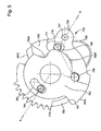
- This output shaft 751 supports a cam 752, which cooperates with a feeler 753 that includes a transmission mechanism 755, to control, directly or indirectly, the movement of a rake 756.
- the cam 752 is preferably, as shown in the figures, a snail-cam, of substantially uniform growth radius, the smallest radius corresponding to the maximum arming position of the motor means 120 of the Figure 1A , and the largest radius corresponding to the disarming position of the motor means 120 of the Figure 4A .
- This rake 756 controls the pivoting of an isolation wheel 770, which comprises the selective stop mechanism 760, and which is arranged to control the position of the blocking lever 771 as a function of the angular position of the parking shaft. output 751, and preferably by acting on a spout 786 that includes the latch 771.
- the ring arresting cam 783 has a plurality of peripheral slots 784.
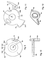
- peripheral slots 784 In the particular embodiment illustrated by the figures, which corresponds to a use for a ringing mechanism 100 which comprises several ring modes, which are switchable by action on a control linkage, and in particular a mode where all the ring tones operate automatically or under manual control of a user, and another mode where the ringtones are only possible in automatic, these notches are four in number: 784A, 784B, 784C, 784D, as visible on the figure 9 .
- Each of these notches 784 is arranged to cooperate, in a particular angular position of the cam 783, with a spout 795 that includes a pawl 789 pushed towards the pivot axis DP by a spring 791.
- the notch 784A corresponds to the minimum level of power reserve, at which the stop of the movement 200 must be triggered.
- the notch 784D corresponds to the maximum level of power reserve, where the motor means 120 are at their maximum capacity, and where the mechanism 760 exerts no hindrance action, neither on the striking mechanism 100, nor on the movement 200.
- the intermediate notches correspond to positions where one chooses to stop, respectively, the operation of all the automatic tones, and the operation of all the ringtones including on manual control of the user.
- This cam 783 is carrying a pin 778 substantially parallel to its pivot axis DP, and protruding from an upper side of a substantially plane flange which comprises at its periphery the notches 784, to cooperate with the other stages of the mobile d isolation 770.
- the cam 783 further comprises a pin 783A protruding substantially parallel to its pivot axis DP and located on a lower side opposite to the upper side of this flange.
- This stud 783A is arranged to fit into the percussion kinematic chain of a striking mechanism 100, and in particular, in the preferred embodiment illustrated by the figures, on the trajectory of a hammer, between the hammer and a stamp or the like, according to the angular position of the ring arresting cam 783.
- the pin 783A is interposed between a first trigger hammer specific to these ringtones, not shown in the figures, and the stamp, or the like, corresponding.
- the pin 783A is still interposed between a second trigger hammer specific to these ringtones, not shown on the figures, and the stamp, or the like, corresponding.
- the mechanism 760 blocks the movement 200, as will be explained later.
- the ring arresting wheel 745 has an external toothed sector 779, which is arranged to cooperate with a set of teeth 788 of the rake 756.
- This ring arresting wheel 745 has an oblong slot 777, which allows a limited movement of the pin 778 of the cam 783, which limits the relative pivoting of the ring arresting wheel 745 relative to the ring arresting cam 783.
- the ring arresting wheel 745 carries a swivel pivot 747 of a two-spout lift 797, which has a first spout 798 rotated about the swivel axis DP, and a second spout. 799 moving away radially substantially.
- the ring arresting wheel 745 carries a raising spring 796 797 in a position tending to reduce the extreme radial position of the second spout 799, and tending to rotate the lift 797 clockwise on the figure 5 .
- the ring arresting wheel 745 comprises, on one of its faces which is, in the example illustrated by the figures, a lower face which is turned towards the upper face of the cam 783, a peripheral clearance 758, between an arm 756 and a boss 757 having a bearing face 746, this arm 756 and this boss 757 flanking the oblong slot 777.
- the bearing surface 746 constitutes a stop surface for the second spout 799 of the two-point rocker beaks 797.
- the ring arresting wheel 745 is, again, carrying a pin 794 substantially parallel to its pivot axis DP, which is projecting from the side of an upper face of the wheel 745 opposite its lower face.
- One end of the toothed sector 779 serves as a support for a return spring 792, fixed on the plate or a bridge of the movement 200, and which tends to rotate this toothed sector 779 in the counter-clockwise direction on the figure 5 .
- the lift 797 may partially cover the light 777, and constitute a stop for the pin 778.
- the motion arresting surprise 780 comprises an arm provided with a function zone 781A, shown in dashed line on the figure 11 , ending at a bearing face 781, and which is arranged to cooperate in support with the spout 786 of the recess rocker 531, and, depending on its position, to block or release the movement 200.
- This surprise 780 has an oblong slot 793, arranged to allow movement of the pin 794 of the ring arresting wheel 745, and which limits the relative pivoting between the ring arresting wheel 745 and the arresting surprise of movement 780.
- This motion arresting surprise 780 also includes a peripheral rolling area 780B, represented in broken lines on the figure 11 , ending in a rolling notch 780A, shown in dashed line on the figure 11 , closer to the pivot axis DP than the rest of the rolling area 780B.
- This peripheral rolling surface is arranged to serve as a rolling track for a roller 790B, pivoted on a pivot 790A of a spring 790 fixed to the plate or a bridge of the movement 200, and which tends to press this roller 790B, substantially radially with respect to the pivot axis DP, rolling bearing on the rolling zone 780B or in the holding position in the rolling slot 780A.
- the selective stopping mechanism 760 further comprises a toothed piece 772, fixed to the plate or a bridge of the movement 200, and which has a first tooth 773 and a second tooth 774, both of which are in the path of the second spout 798. the lift 797, when it is in its maximum radial extent.
- the gap between this first tooth 773 and this second tooth 774 is close to the distance of the extreme positions that the pin 778 can occupy in the light 777 of the ring arresting wheel 745.
- the ends of maximum radial extension of these teeth 773 and 774 towards the pivot axis DP are located on the same radius RE.
- the complete disarming position of the motor means 120 corresponds to the engagement of the notch 784A of the ringer arresting cam 783 with the beak 795 of the ratchet 789.
- the post 783A blocks any ringing, and the toothed sector 788 of the rake 756 is in maximum remote position of the isolation device 770.
- the spring 790 is arranged to deform only very little buckling, it then tends to push the roller 790B, from the running surface 780B in the notch 780A, and thus to rotate the surprise 780 in the clockwise direction of the figure 5 , and thus to release the spout 786 of the blocking latch 771, the movement 200 is then released.
- the existing game between the pin 794 of the wheel 745 and the oblong light 793 of the surprise 780 allows to release the latter at once, and perform an all or nothing maneuver, to move the spout 786 in one fell swoop.
- the surprise 780 being locked in position by the action of the roller 790B in the notch 780A, the possible pivoting stroke of the wheel 745 relative to this fixed position of the surprise 780 is limited by the movement of the pin 794 of the wheel 745 in the oblong light 793 of surprise 780.
- each of its two teeth 773 and 774 causes the lift 797 to pivot about its pivot axis 747, to allow the first spout 798 to take a position in which its maximum radial extension is less than the radius RE.
- the second spout 799 must then push the pin 770, and thus rotate the cam 783, to occupy a new position on another of the notches 784, in this case 784B when the first spout 798 passes the first tooth 773, and 784C when it passes the second tooth 774.
- the spring 796 restores the first spout 798 in its maximum extension after the passage of each of the teeth 773 and 774.
- the maximum pivoting of the wheel 745 drives the pin 778 of the cam 783, and passes it into the angular position where the notch 784D cooperates with the spout 795 of the pawl 789 .
- the disarming of the motor means 120 results in a movement of the rake 756 in the direction B of the Figure 1A .
- the probe 753 is then on the smallest radius of the cam 752, when the arming motor means 120 is maximum.
- the spout 795 of the pawl 789 is then in the notch 784D, which is the deepest.
- the 790B roller of the 790 spring then rolls on the running surface 780B.
- the spout 786 of the latch 771 is remote from the bearing face 781 of the surprise, and faces it.
- the wheel 745 then rotates clockwise on the figure 5 driving pin 778 of cam 783 with the end of light 777 furthest from pivot 747.
- each tooth, second tooth 774, then first tooth 773 is successively crossed by the first spout 798, causing each time a pivoting of the lift 797 against the spring 796.
- the continued pivoting of the wheel 745 causes the pivoting of the cam 783, and the jump from one to the other successive notches, 784 D to 784 C, then 784 B.
- the crossing position of the second tooth 774 corresponds to the position of the beak 795 of the pawl 789 in the notch 784C corresponding to the blocking of the automatic tones, and leads to the blocking, by the pin 783A of the cam 783, the first trigger hammer specific to these ringtones, and the stamp, or the like, corresponding.
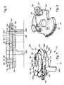
- the figure 3 illustrates a state where the automatic ring is blocked, and where the movement works.
- the first spout 798 is between the second tooth 774 and the first tooth 773.
- the spout 795 of the pawl 789 is in the notch 784C, and the hammer 531 is thus blocked.
- the 790B roller from the 790 spring still rolls on the 780B running surface.
- the spout 786 of the locking lever 771 approaches the bearing face 781 of the surprise 780.
- the figure 4 illustrates a state where all ringtones are blocked, and where the movement works.
- the passage of the first tooth 773 corresponds to the position of the spout 795 of the pawl 789 in the notch 784B corresponding to the blocking of the ringtones whose ringtones triggered manually by the user, the pin 783A is still interposed between a second own trigger hammer to these ringtones, and the timbre, or the like, corresponding.
- the 790B roller of the 790 spring still rolls on the running surface 780B, and approaches the notch 784A.
- the spout 786 of the blocking rocker 771 approaches and comes into contact with the bearing surface 781 of the surprise 780.
- the figure 4 illustrates a state where all ringtones are blocked, and the movement is blocked.
Landscapes
- Physics & Mathematics (AREA)
- General Physics & Mathematics (AREA)
- Acoustics & Sound (AREA)
- Toys (AREA)
- Percussion Or Vibration Massage (AREA)
- Measurement Of Unknown Time Intervals (AREA)
- Electromechanical Clocks (AREA)
- Transmission Devices (AREA)
- Apparatus For Radiation Diagnosis (AREA)
Claims (10)
- Zeitmessgerät (1000), das Motormittel (120), ein Werk (200), einen Gangreserve-Steuermechanismus (750) der Motormittel (120), der eine Ausgangswelle (751) aufweist, deren Winkelposition die auf Seiten der Motormittel (120) verfügbare Gangreserve angibt, und einen Läutwerkmechanismus (100), der durch einen Läutwerksteuermechanismus (1) gesteuert wird, der eine Sperrwippe (771) aufweist, die dafür ausgelegt ist, die Funktion des Werks (200) zu sperren, umfasst, wobei das Zeitmessgerät außerdem eingefügt zwischen die Ausgangswelle (751) und die Sperrwippe (771) einen Mechanismus (760) für wahlweises Anhalten umfasst, um die Läutwerke des Zeitmessgeräts (1000) als Funktion des verfügbaren Motordrehmoments der Motormittel (120) wahlweise anzuhalten, wobei der Mechanismus (760) für wahlweises Anhalten dafür ausgelegt ist, das auf Seiten der Motormittel (120) verfügbare Drehmoment zu steuern, indem der Gang der Läutwerke als Funktion der Winkelposition der Ausgangswelle (751) begrenzt wird oder nicht, um einen Mechanismus zum Auslösen aller oder eines Teils der verfügbaren Läutwerke auf Seiten des Läutwerkmechanismus (100) über einen Kraftübertragungsmechanismus (755) zu steuern, der ein bewegliches Isolierelement (770) steuert, das der Mechanismus (760) für wahlweises Anhalten trägt und dafür ausgelegt ist, die Position der Sperrwippe (771) zu steuern, und außerdem dafür ausgelegt ist, die Bewegung eines Läutwerk-Steuergestänges (700) freizugeben oder zu verhindern und/oder einen Schlag eines Hammers auf eine Tonfeder zuzulassen oder zu verhindern.
- Zeitmessgerät (1000) nach Anspruch 1, dadurch gekennzeichnet, dass der Mechanismus (760) für wahlweises Anhalten einen Nocken (752), der dafür ausgelegt ist, mit der Ausgangswelle (751) zu schwenken und mit einem Taster (753) zusammenzuwirken, den der Kraftübertragungsmechanismus (755) trägt, um direkt oder indirekt die Bewegung eines Rechens (756) zu steuern, der die Schwenkung einer Eingangsstufe des beweglichen Isolierelements (770) steuert, aufweist, wobei das bewegliche Isolierelement (770) in gegenseitiger Überlagerung und dafür ausgelegt, um dieselbe Schwenkachse (DP) mit relativ zueinander begrenzten Winkelausschlägen zu schwenken eine Haltenocke des Läutwerks (783) und ein Halterad des Läutwerks (745) und ein Haltüberstand des Werks (780) enthält und entgegen oder unter der Wirkung elastischer Rückstellmittel wirkt, und um die Bewegung einer Ausgangsstufe zu steuern, die durch einen Halteüberstand des Werks (780) gebildet ist, wovon eine Abstützfläche (781) und eine Funktionszone (781A), die miteinander verbunden sind, dafür ausgelegt sind, mit der Sperrwippe (771) zusammenzuwirken, indem sie einen Anschlag bzw. eine Rampe für die Sperrwippe (771) bilden.
- Zeitmessgerät (1000) nach Anspruch 2, dadurch gekennzeichnet, dass der Mechanismus (760) für wahlweises Anhalten montiert außerhalb des beweglichen Isolierelements (770) ein gezahntes Teil (772) umfasst, das wenigstens einen ersten Zahn (773) und einen zweiten Zahn (774) aufweist, die im Wesentlichen radial zu der Schwenkachse (DP) vorstehen, und deren Enden sich auf demselben ersten Radius (RE) in Bezug auf die Schwenkachse (DP) und in einem ersten Winkelabstand in Bezug darauf befinden, und dass die Eingangsstufe einerseits einen gezahnten Sektor (779), der dafür ausgelegt ist, auf komplementäre Weise mit dem Rechen (756) für seine Schwenksteuerung zusammenzuwirken, und andererseits eine Platte (545), die einen Hebel mit zwei Spitzen (797) trägt, der exzentrisch in Bezug auf die Schwenkachse (DP) schwenkt, umfasst, wobei der Hebel (797) eine erste Spitze (798) aufweist, die im Wesentlichen radial in Bezug auf die Schwenkachse (DP) entgegengesetzt hierzu vorsteht, und wovon das Ende zwischen zwei Positionen beweglich ist, deren Radius in Bezug auf die Schwenkachse (DP) kleiner bzw. größer ist als der erste Radius (RE).
- Zeitmessgerät (1000) nach Anspruch 3, dadurch gekennzeichnet, dass der Hebel mit zwei Spitzen (797) eine zweite Spitze (799) aufweist, die in Bezug auf die Schwenkachse (DP) im Wesentlichen radial ist und zu dieser gewendet ist, und dass das bewegliche Isolierelement (770) einen weiteren Nocken (783) umfasst, der in Bezug auf die Schwenkachse (DP) schwenkbar ist und einen Zapfen (778) trägt, der zu der Schwenkachse (DP) im Wesentlichen parallel ist, wobei der Zapfen (778) auf begrenzte Weise in einem Langloch (777), das die Platte (545) aufweist, in Winkelrichtung in Bezug auf die Schwenkachse (DP) entgegen der zweiten Spitze (799), die gegen den Zapfen (778) durch die elastischen Rückstellmittel (796) geschoben wird, beweglich ist.
- Zeitmessgerät (1000) nach Anspruch 4, dadurch gekennzeichnet, dass der Nocken (783) mehrere Umfangskerben (784A; 784B; 784C; 784D) aufweist, die jeweils dafür ausgelegt sind, in einer bestimmten Winkelposition des Nockens (783) mit einer Spitze (795) zusammenzuwirken, die ein Einrastarm (789) aufweist, der durch die elastischen Rückstellmittel (791) gegen den Nocken (783) geschoben wird.
- Zeitmessgerät (1000) nach Anspruch 3, dadurch gekennzeichnet, dass die Eingangsstufe einen Zapfen (794) trägt, der zu der Schwenkachse (DP) im Wesentlichen parallel ist und auf begrenzte Weise in einem Langloch (793), das der Halteüberstand des Werks (780) aufweist, in Winkelrichtung in Bezug auf die Schwenkachse (DP) beweglich ist, um den relativen Winkelausschlag zwischen dem Halteüberstand des Werks (780) und dem Halterad des Läutwerks (745) zu begrenzen.
- Zeitmessgerät (1000) nach Anspruch 3, dadurch gekennzeichnet, dass der gezahnte Sektor (779) ein Ende aufweist, das als Abstützung für die elastischen Rückstellmittel (792) dient, die bestrebt sind, den gezahnten Sektor (779) von dem Rechen (756) zu entfernen.
- Zeitmessgerät (1000) nach Anspruch 2, dadurch gekennzeichnet, dass der Halteüberstand des Werks (780) eine Umfangsrolloberfläche (780B) umfasst, die mit einer Kerbe (780A) verbunden ist, wobei beide dafür ausgelegt sind, mit einer Rolle (790B) zusammenzuwirken, die an einem Ende einer Feder (790), die einer im Wesentlichen radialen Bewegung in Bezug auf die Schwenkachse (DP) unterliegt, schwenkbar montiert ist.
- Zeitmessgerät (1000) nach Anspruch 4 oder 5, dadurch gekennzeichnet, dass der Nocken (783) einen Stift (783A) umfasst, der dafür ausgelegt ist, entsprechend der Winkelposition des Nockens (783) einen Schlag wenigstens eines Hammers auf eine Tonfeder zu verhindern oder zuzulassen, indem er zwischen diese eintritt oder nicht.
- Zeitmessgerät (1000) nach den Ansprüchen 5 und 9, dadurch gekennzeichnet, dass in einer Position der Spitze (795) in einer Kerbe (784C), die dem Sperren des automatischen Läutwerks entspricht, der Stift (783A) zwischen einen eigentlichen Auslösehammer des Läutwerks und die entsprechende Tonfeder eingefügt ist und dass in einer Position der Spitze (795) in einer Kerbe (784B), die der Sperrung sämtlicher Läutwerke entspricht, darunter jenen Läutwerken, die vom Anwender manuell ausgelöst werden, der Stift (783A) auch zwischen einen zweiten eigentlichen Auslösehammer dieser Läutwerke und die entsprechende Tonfeder eingefügt ist.
Priority Applications (5)
| Application Number | Priority Date | Filing Date | Title |
|---|---|---|---|
| CH00484/11A CH704672A2 (fr) | 2011-03-22 | 2011-03-22 | Mécanisme d'arrêt sélectif des sonneries d'une pièce d'horlogerie en fonction du couple moteur disponible. |
| EP11159238.2A EP2503405B1 (de) | 2011-03-22 | 2011-03-22 | Uhr umfassend einen Schlagwerk sowie einen Mechanismus zur selektiven stoppen dieses Schlagwerks |
| US13/424,603 US8730768B2 (en) | 2011-03-22 | 2012-03-20 | Mechanism for selectively stopping the striking mechanisms of a timepiece according to the available drive torque |
| CN201210077869.7A CN102692859B (zh) | 2011-03-22 | 2012-03-22 | 用于根据可用驱动力矩选择性地停止钟表报时机构的机构 |
| JP2012065122A JP5537584B2 (ja) | 2011-03-22 | 2012-03-22 | 利用可能な駆動トルクにより打撃機構を選択的に停止することが出来る時計 |
Applications Claiming Priority (1)
| Application Number | Priority Date | Filing Date | Title |
|---|---|---|---|
| EP11159238.2A EP2503405B1 (de) | 2011-03-22 | 2011-03-22 | Uhr umfassend einen Schlagwerk sowie einen Mechanismus zur selektiven stoppen dieses Schlagwerks |
Publications (2)
| Publication Number | Publication Date |
|---|---|
| EP2503405A1 EP2503405A1 (de) | 2012-09-26 |
| EP2503405B1 true EP2503405B1 (de) | 2014-07-30 |
Family
ID=44680985
Family Applications (1)
| Application Number | Title | Priority Date | Filing Date |
|---|---|---|---|
| EP11159238.2A Active EP2503405B1 (de) | 2011-03-22 | 2011-03-22 | Uhr umfassend einen Schlagwerk sowie einen Mechanismus zur selektiven stoppen dieses Schlagwerks |
Country Status (5)
| Country | Link |
|---|---|
| US (1) | US8730768B2 (de) |
| EP (1) | EP2503405B1 (de) |
| JP (1) | JP5537584B2 (de) |
| CN (1) | CN102692859B (de) |
| CH (1) | CH704672A2 (de) |
Cited By (1)
| Publication number | Priority date | Publication date | Assignee | Title |
|---|---|---|---|---|
| EP3435169A1 (de) | 2017-07-25 | 2019-01-30 | Blancpain SA | Arretiermechanismus für schlagwerkmechanismus einer uhr |
Families Citing this family (13)
| Publication number | Priority date | Publication date | Assignee | Title |
|---|---|---|---|---|
| US8995238B2 (en) * | 2013-03-28 | 2015-03-31 | Rolex S.A. | Device for displaying time information |
| CN104656409B (zh) * | 2013-11-19 | 2017-04-19 | 天津海鸥表业集团有限公司 | 一种带有保险结构的指针飞返式小时指示机构 |
| DE102014115642B3 (de) * | 2014-10-28 | 2015-11-05 | Lange Uhren Gmbh | Uhr |
| CN106292246B (zh) * | 2015-05-14 | 2018-06-26 | 天津海鸥表业集团有限公司 | 一种机械表中的自动报时启动控制结构 |
| EP3306416B1 (de) | 2016-10-04 | 2019-08-21 | ETA SA Manufacture Horlogère Suisse | Mechanisches uhrwerk mit erfassung der gangreserve |
| EP3306415B1 (de) * | 2016-10-04 | 2020-05-20 | ETA SA Manufacture Horlogère Suisse | Mechanisches uhrwerk mit erfassung der gangreserve |
| EP3435174B1 (de) * | 2017-07-25 | 2021-06-16 | Blancpain SA | Moduswahlschalter für schlagwerk für armbanduhr oder andere uhr |
| JP6740323B2 (ja) * | 2017-07-25 | 2020-08-12 | ブランパン・エス アー | 計時器、特に、ストライク機構を備えた計時器、のためのトルクの平滑化 |
| EP3502801B1 (de) * | 2017-12-19 | 2021-02-17 | Omega SA | Repetitionsmechanismus für chronograph mit sicherung |
| EP3502802B1 (de) * | 2017-12-19 | 2021-02-17 | Omega SA | Repetitionsmechanismus für chronograph mit sicherung |
| EP3575886B1 (de) * | 2018-05-28 | 2021-03-10 | Blancpain SA | Uhr mit schlagwerk und einschaltsicherung |
| EP3845975B1 (de) * | 2019-12-31 | 2024-03-13 | Omega SA | Sicherheitsvorrichtung und schlagwerkmechanismus |
| EP3968094A1 (de) * | 2020-09-09 | 2022-03-16 | Omega SA | Wahlmechanismus eines uhrwerks |
Family Cites Families (10)
| Publication number | Priority date | Publication date | Assignee | Title |
|---|---|---|---|---|
| DE602005006733D1 (de) * | 2005-03-31 | 2008-06-26 | Zenith Internat S A | Repetieruhr mit einem Minutenrepetiermechanismus |
| EP1708051A1 (de) | 2005-03-31 | 2006-10-04 | Zenith International SA | Uhr mit einem Wecker |
| EP1760545A1 (de) * | 2005-09-01 | 2007-03-07 | Montres Journe S.A. | Uhr mit einem Schlagwerk |
| EP1925997B1 (de) * | 2006-11-21 | 2013-02-27 | Manufacture Claret SA | Schlagwerk |
| EP1925995B1 (de) * | 2006-11-21 | 2014-06-18 | Christophe Claret Engineering S.A. | Schlagwerk |
| EP2073076B1 (de) * | 2007-12-20 | 2012-06-13 | Montres Breguet S.A. | Betätigungsmechanismus eines weckers |
| EP2133758A1 (de) * | 2008-06-12 | 2009-12-16 | Blancpain S.A. | Uhr mit einem Schlagwerkmechanismus |
| EP2226688B1 (de) * | 2009-03-05 | 2011-09-07 | Vaucher Manufacture Fleurier S.A. | Uhr |
| CH700849A1 (fr) * | 2009-04-28 | 2010-10-29 | Frank Mueller Watchland S A | Piece d'horlogerie. |
| CH701257B1 (fr) * | 2009-06-11 | 2014-01-31 | Richemont Int Sa | Mécanisme de sonnerie pour pièce d'horlogerie. |
-
2011
- 2011-03-22 EP EP11159238.2A patent/EP2503405B1/de active Active
- 2011-03-22 CH CH00484/11A patent/CH704672A2/fr not_active Application Discontinuation
-
2012
- 2012-03-20 US US13/424,603 patent/US8730768B2/en active Active
- 2012-03-22 CN CN201210077869.7A patent/CN102692859B/zh active Active
- 2012-03-22 JP JP2012065122A patent/JP5537584B2/ja active Active
Cited By (1)
| Publication number | Priority date | Publication date | Assignee | Title |
|---|---|---|---|---|
| EP3435169A1 (de) | 2017-07-25 | 2019-01-30 | Blancpain SA | Arretiermechanismus für schlagwerkmechanismus einer uhr |
Also Published As
| Publication number | Publication date |
|---|---|
| EP2503405A1 (de) | 2012-09-26 |
| JP5537584B2 (ja) | 2014-07-02 |
| CN102692859A (zh) | 2012-09-26 |
| CH704672A2 (fr) | 2012-09-28 |
| CN102692859B (zh) | 2014-11-12 |
| JP2012198212A (ja) | 2012-10-18 |
| US20120243385A1 (en) | 2012-09-27 |
| US8730768B2 (en) | 2014-05-20 |
Similar Documents
| Publication | Publication Date | Title |
|---|---|---|
| EP2503405B1 (de) | Uhr umfassend einen Schlagwerk sowie einen Mechanismus zur selektiven stoppen dieses Schlagwerks | |
| EP1852755B1 (de) | Uhr mit einem Minutenrepetiermechanismus | |
| EP1970778B1 (de) | Uhr mit Anzeige der Gangreserve | |
| EP3001258B1 (de) | Schlagwerkmechanismus mit unterschiedlichen schlagwerken | |
| EP2498143B1 (de) | Isolationsmechanismus zwischen Uhrmechanismen zur Auslösung verschiedener Schlagwerkssignale | |
| EP2498147B1 (de) | Schlagwerksblock und Antriebsmechanismus für Weckerwerk für Uhren mit Schlagwerken | |
| EP1798611B1 (de) | Uhr, die einen Schlagwerkmechanismus mit sofortiger Auslösung umfasst | |
| CH704591B1 (fr) | Mécanisme de sonnerie à répétition minutes comportant un mécanisme de sécurité contre des manipulations intempestives. | |
| EP2498149B1 (de) | Zeitbegrenzungsmechanismus für Uhrmechanismus | |
| EP3435169B1 (de) | Arretiermechanismus für schlagwerkmechanismus einer uhr | |
| CH704625A2 (fr) | Mécanisme de sonnerie de réveil par la grande sonnerie. | |
| EP2503411A1 (de) | Ewiger Kalender mit Einzelsperre | |
| EP1798610B1 (de) | Uhr, die einen Schlagwerkmechanismus mit einem einzigen Sperrkegel umfasst | |
| CH703361A2 (fr) | Mouvement horloger presentant des fonctions de chronographe et de compte-a-rebours. | |
| EP2363765B1 (de) | Vorrichtung zur sequenziellen steuerung mindestens zwei schöpfer eines uhrwerks | |
| EP3108307B1 (de) | Schlagwerkvorrichtung für eine uhr | |
| EP3489765A1 (de) | Armbanduhr mit schlagwerkmechanismus mit einstellvorrichtung und sicherung der zeiteinstellung | |
| EP3575886B1 (de) | Uhr mit schlagwerk und einschaltsicherung | |
| CH704590A2 (fr) | Mécanisme d'isolement entre mécanismes horlogers de déclenchement de différents signaux sonores. | |
| CH715723B1 (fr) | Mécanisme de saut instantané d'un mobile d'affichage. | |
| EP3361323A1 (de) | System zum aufziehen einer uhr | |
| CH714363B1 (fr) | Système d'entretien d'un oscillateur horloger. | |
| EP4312087A1 (de) | Jahreskalendermechanismus für uhrwerk | |
| EP4575656A1 (de) | Uhrwerk, das eine reguliervorrichtung umfasst | |
| EP4310603A1 (de) | Uhrwerk |
Legal Events
| Date | Code | Title | Description |
|---|---|---|---|
| PUAI | Public reference made under article 153(3) epc to a published international application that has entered the european phase |
Free format text: ORIGINAL CODE: 0009012 |
|
| AK | Designated contracting states |
Kind code of ref document: A1 Designated state(s): AL AT BE BG CH CY CZ DE DK EE ES FI FR GB GR HR HU IE IS IT LI LT LU LV MC MK MT NL NO PL PT RO RS SE SI SK SM TR |
|
| AX | Request for extension of the european patent |
Extension state: BA ME |
|
| 17P | Request for examination filed |
Effective date: 20130326 |
|
| RIC1 | Information provided on ipc code assigned before grant |
Ipc: G04B 9/02 20060101AFI20131008BHEP |
|
| GRAP | Despatch of communication of intention to grant a patent |
Free format text: ORIGINAL CODE: EPIDOSNIGR1 |
|
| INTG | Intention to grant announced |
Effective date: 20131220 |
|
| GRAP | Despatch of communication of intention to grant a patent |
Free format text: ORIGINAL CODE: EPIDOSNIGR1 |
|
| INTG | Intention to grant announced |
Effective date: 20140429 |
|
| GRAJ | Information related to disapproval of communication of intention to grant by the applicant or resumption of examination proceedings by the epo deleted |
Free format text: ORIGINAL CODE: EPIDOSDIGR1 |
|
| INTG | Intention to grant announced |
Effective date: 20140507 |
|
| GRAP | Despatch of communication of intention to grant a patent |
Free format text: ORIGINAL CODE: EPIDOSNIGR1 |
|
| GRAS | Grant fee paid |
Free format text: ORIGINAL CODE: EPIDOSNIGR3 |
|
| GRAA | (expected) grant |
Free format text: ORIGINAL CODE: 0009210 |
|
| INTG | Intention to grant announced |
Effective date: 20140606 |
|
| AK | Designated contracting states |
Kind code of ref document: B1 Designated state(s): AL AT BE BG CH CY CZ DE DK EE ES FI FR GB GR HR HU IE IS IT LI LT LU LV MC MK MT NL NO PL PT RO RS SE SI SK SM TR |
|
| REG | Reference to a national code |
Ref country code: GB Ref legal event code: FG4D Free format text: NOT ENGLISH |
|
| REG | Reference to a national code |
Ref country code: CH Ref legal event code: EP |
|
| REG | Reference to a national code |
Ref country code: AT Ref legal event code: REF Ref document number: 680253 Country of ref document: AT Kind code of ref document: T Effective date: 20140815 |
|
| REG | Reference to a national code |
Ref country code: IE Ref legal event code: FG4D Free format text: LANGUAGE OF EP DOCUMENT: FRENCH |
|
| REG | Reference to a national code |
Ref country code: DE Ref legal event code: R096 Ref document number: 602011008672 Country of ref document: DE Effective date: 20140911 |
|
| REG | Reference to a national code |
Ref country code: CH Ref legal event code: NV Representative=s name: ICB INGENIEURS CONSEILS EN BREVETS SA, CH |
|
| REG | Reference to a national code |
Ref country code: AT Ref legal event code: MK05 Ref document number: 680253 Country of ref document: AT Kind code of ref document: T Effective date: 20140730 |
|
| REG | Reference to a national code |
Ref country code: NL Ref legal event code: VDEP Effective date: 20140730 |
|
| REG | Reference to a national code |
Ref country code: LT Ref legal event code: MG4D |
|
| PG25 | Lapsed in a contracting state [announced via postgrant information from national office to epo] |
Ref country code: GR Free format text: LAPSE BECAUSE OF FAILURE TO SUBMIT A TRANSLATION OF THE DESCRIPTION OR TO PAY THE FEE WITHIN THE PRESCRIBED TIME-LIMIT Effective date: 20141031 Ref country code: SE Free format text: LAPSE BECAUSE OF FAILURE TO SUBMIT A TRANSLATION OF THE DESCRIPTION OR TO PAY THE FEE WITHIN THE PRESCRIBED TIME-LIMIT Effective date: 20140730 Ref country code: NO Free format text: LAPSE BECAUSE OF FAILURE TO SUBMIT A TRANSLATION OF THE DESCRIPTION OR TO PAY THE FEE WITHIN THE PRESCRIBED TIME-LIMIT Effective date: 20141030 Ref country code: PT Free format text: LAPSE BECAUSE OF FAILURE TO SUBMIT A TRANSLATION OF THE DESCRIPTION OR TO PAY THE FEE WITHIN THE PRESCRIBED TIME-LIMIT Effective date: 20141202 Ref country code: LT Free format text: LAPSE BECAUSE OF FAILURE TO SUBMIT A TRANSLATION OF THE DESCRIPTION OR TO PAY THE FEE WITHIN THE PRESCRIBED TIME-LIMIT Effective date: 20140730 Ref country code: BG Free format text: LAPSE BECAUSE OF FAILURE TO SUBMIT A TRANSLATION OF THE DESCRIPTION OR TO PAY THE FEE WITHIN THE PRESCRIBED TIME-LIMIT Effective date: 20141030 Ref country code: ES Free format text: LAPSE BECAUSE OF FAILURE TO SUBMIT A TRANSLATION OF THE DESCRIPTION OR TO PAY THE FEE WITHIN THE PRESCRIBED TIME-LIMIT Effective date: 20140730 Ref country code: FI Free format text: LAPSE BECAUSE OF FAILURE TO SUBMIT A TRANSLATION OF THE DESCRIPTION OR TO PAY THE FEE WITHIN THE PRESCRIBED TIME-LIMIT Effective date: 20140730 |
|
| PG25 | Lapsed in a contracting state [announced via postgrant information from national office to epo] |
Ref country code: PL Free format text: LAPSE BECAUSE OF FAILURE TO SUBMIT A TRANSLATION OF THE DESCRIPTION OR TO PAY THE FEE WITHIN THE PRESCRIBED TIME-LIMIT Effective date: 20140730 Ref country code: NL Free format text: LAPSE BECAUSE OF FAILURE TO SUBMIT A TRANSLATION OF THE DESCRIPTION OR TO PAY THE FEE WITHIN THE PRESCRIBED TIME-LIMIT Effective date: 20140730 Ref country code: CY Free format text: LAPSE BECAUSE OF FAILURE TO SUBMIT A TRANSLATION OF THE DESCRIPTION OR TO PAY THE FEE WITHIN THE PRESCRIBED TIME-LIMIT Effective date: 20140730 Ref country code: IS Free format text: LAPSE BECAUSE OF FAILURE TO SUBMIT A TRANSLATION OF THE DESCRIPTION OR TO PAY THE FEE WITHIN THE PRESCRIBED TIME-LIMIT Effective date: 20141130 Ref country code: HR Free format text: LAPSE BECAUSE OF FAILURE TO SUBMIT A TRANSLATION OF THE DESCRIPTION OR TO PAY THE FEE WITHIN THE PRESCRIBED TIME-LIMIT Effective date: 20140730 Ref country code: LV Free format text: LAPSE BECAUSE OF FAILURE TO SUBMIT A TRANSLATION OF THE DESCRIPTION OR TO PAY THE FEE WITHIN THE PRESCRIBED TIME-LIMIT Effective date: 20140730 Ref country code: AT Free format text: LAPSE BECAUSE OF FAILURE TO SUBMIT A TRANSLATION OF THE DESCRIPTION OR TO PAY THE FEE WITHIN THE PRESCRIBED TIME-LIMIT Effective date: 20140730 Ref country code: RS Free format text: LAPSE BECAUSE OF FAILURE TO SUBMIT A TRANSLATION OF THE DESCRIPTION OR TO PAY THE FEE WITHIN THE PRESCRIBED TIME-LIMIT Effective date: 20140730 |
|
| PG25 | Lapsed in a contracting state [announced via postgrant information from national office to epo] |
Ref country code: CZ Free format text: LAPSE BECAUSE OF FAILURE TO SUBMIT A TRANSLATION OF THE DESCRIPTION OR TO PAY THE FEE WITHIN THE PRESCRIBED TIME-LIMIT Effective date: 20140730 Ref country code: EE Free format text: LAPSE BECAUSE OF FAILURE TO SUBMIT A TRANSLATION OF THE DESCRIPTION OR TO PAY THE FEE WITHIN THE PRESCRIBED TIME-LIMIT Effective date: 20140730 Ref country code: SK Free format text: LAPSE BECAUSE OF FAILURE TO SUBMIT A TRANSLATION OF THE DESCRIPTION OR TO PAY THE FEE WITHIN THE PRESCRIBED TIME-LIMIT Effective date: 20140730 Ref country code: IT Free format text: LAPSE BECAUSE OF FAILURE TO SUBMIT A TRANSLATION OF THE DESCRIPTION OR TO PAY THE FEE WITHIN THE PRESCRIBED TIME-LIMIT Effective date: 20140730 Ref country code: RO Free format text: LAPSE BECAUSE OF FAILURE TO SUBMIT A TRANSLATION OF THE DESCRIPTION OR TO PAY THE FEE WITHIN THE PRESCRIBED TIME-LIMIT Effective date: 20140730 Ref country code: DK Free format text: LAPSE BECAUSE OF FAILURE TO SUBMIT A TRANSLATION OF THE DESCRIPTION OR TO PAY THE FEE WITHIN THE PRESCRIBED TIME-LIMIT Effective date: 20140730 |
|
| REG | Reference to a national code |
Ref country code: DE Ref legal event code: R097 Ref document number: 602011008672 Country of ref document: DE |
|
| PLBE | No opposition filed within time limit |
Free format text: ORIGINAL CODE: 0009261 |
|
| STAA | Information on the status of an ep patent application or granted ep patent |
Free format text: STATUS: NO OPPOSITION FILED WITHIN TIME LIMIT |
|
| 26N | No opposition filed |
Effective date: 20150504 |
|
| PG25 | Lapsed in a contracting state [announced via postgrant information from national office to epo] |
Ref country code: LU Free format text: LAPSE BECAUSE OF FAILURE TO SUBMIT A TRANSLATION OF THE DESCRIPTION OR TO PAY THE FEE WITHIN THE PRESCRIBED TIME-LIMIT Effective date: 20150322 Ref country code: MC Free format text: LAPSE BECAUSE OF FAILURE TO SUBMIT A TRANSLATION OF THE DESCRIPTION OR TO PAY THE FEE WITHIN THE PRESCRIBED TIME-LIMIT Effective date: 20140730 |
|
| PG25 | Lapsed in a contracting state [announced via postgrant information from national office to epo] |
Ref country code: SI Free format text: LAPSE BECAUSE OF FAILURE TO SUBMIT A TRANSLATION OF THE DESCRIPTION OR TO PAY THE FEE WITHIN THE PRESCRIBED TIME-LIMIT Effective date: 20140730 |
|
| REG | Reference to a national code |
Ref country code: IE Ref legal event code: MM4A |
|
| PG25 | Lapsed in a contracting state [announced via postgrant information from national office to epo] |
Ref country code: IE Free format text: LAPSE BECAUSE OF NON-PAYMENT OF DUE FEES Effective date: 20150322 |
|
| REG | Reference to a national code |
Ref country code: FR Ref legal event code: PLFP Year of fee payment: 6 |
|
| PG25 | Lapsed in a contracting state [announced via postgrant information from national office to epo] |
Ref country code: MT Free format text: LAPSE BECAUSE OF FAILURE TO SUBMIT A TRANSLATION OF THE DESCRIPTION OR TO PAY THE FEE WITHIN THE PRESCRIBED TIME-LIMIT Effective date: 20140730 |
|
| REG | Reference to a national code |
Ref country code: FR Ref legal event code: PLFP Year of fee payment: 7 |
|
| PG25 | Lapsed in a contracting state [announced via postgrant information from national office to epo] |
Ref country code: SM Free format text: LAPSE BECAUSE OF FAILURE TO SUBMIT A TRANSLATION OF THE DESCRIPTION OR TO PAY THE FEE WITHIN THE PRESCRIBED TIME-LIMIT Effective date: 20140730 Ref country code: HU Free format text: LAPSE BECAUSE OF FAILURE TO SUBMIT A TRANSLATION OF THE DESCRIPTION OR TO PAY THE FEE WITHIN THE PRESCRIBED TIME-LIMIT; INVALID AB INITIO Effective date: 20110322 |
|
| PG25 | Lapsed in a contracting state [announced via postgrant information from national office to epo] |
Ref country code: BE Free format text: LAPSE BECAUSE OF NON-PAYMENT OF DUE FEES Effective date: 20150331 |
|
| PG25 | Lapsed in a contracting state [announced via postgrant information from national office to epo] |
Ref country code: TR Free format text: LAPSE BECAUSE OF FAILURE TO SUBMIT A TRANSLATION OF THE DESCRIPTION OR TO PAY THE FEE WITHIN THE PRESCRIBED TIME-LIMIT Effective date: 20140730 |
|
| REG | Reference to a national code |
Ref country code: FR Ref legal event code: PLFP Year of fee payment: 8 |
|
| PG25 | Lapsed in a contracting state [announced via postgrant information from national office to epo] |
Ref country code: MK Free format text: LAPSE BECAUSE OF FAILURE TO SUBMIT A TRANSLATION OF THE DESCRIPTION OR TO PAY THE FEE WITHIN THE PRESCRIBED TIME-LIMIT Effective date: 20140730 |
|
| PG25 | Lapsed in a contracting state [announced via postgrant information from national office to epo] |
Ref country code: AL Free format text: LAPSE BECAUSE OF FAILURE TO SUBMIT A TRANSLATION OF THE DESCRIPTION OR TO PAY THE FEE WITHIN THE PRESCRIBED TIME-LIMIT Effective date: 20140730 |
|
| P01 | Opt-out of the competence of the unified patent court (upc) registered |
Effective date: 20230611 |
|
| PGFP | Annual fee paid to national office [announced via postgrant information from national office to epo] |
Ref country code: CH Payment date: 20250401 Year of fee payment: 15 |
|
| REG | Reference to a national code |
Ref country code: CH Ref legal event code: U11 Free format text: ST27 STATUS EVENT CODE: U-0-0-U10-U11 (AS PROVIDED BY THE NATIONAL OFFICE) Effective date: 20260401 |
|
| PGFP | Annual fee paid to national office [announced via postgrant information from national office to epo] |
Ref country code: GB Payment date: 20260219 Year of fee payment: 16 |
|
| PGFP | Annual fee paid to national office [announced via postgrant information from national office to epo] |
Ref country code: DE Payment date: 20260219 Year of fee payment: 16 |
|
| PGFP | Annual fee paid to national office [announced via postgrant information from national office to epo] |
Ref country code: FR Payment date: 20260220 Year of fee payment: 16 |