EP2522464A2 - Mordache et procédé de fabrication d'un emmanchement par pressage - Google Patents
Mordache et procédé de fabrication d'un emmanchement par pressage Download PDFInfo
- Publication number
- EP2522464A2 EP2522464A2 EP12152832A EP12152832A EP2522464A2 EP 2522464 A2 EP2522464 A2 EP 2522464A2 EP 12152832 A EP12152832 A EP 12152832A EP 12152832 A EP12152832 A EP 12152832A EP 2522464 A2 EP2522464 A2 EP 2522464A2
- Authority
- EP
- European Patent Office
- Prior art keywords
- contour
- jaw
- pressing jaw
- pressing
- main inlet
- Prior art date
- Legal status (The legal status is an assumption and is not a legal conclusion. Google has not performed a legal analysis and makes no representation as to the accuracy of the status listed.)
- Granted
Links
Images



Classifications
-
- B—PERFORMING OPERATIONS; TRANSPORTING
- B25—HAND TOOLS; PORTABLE POWER-DRIVEN TOOLS; MANIPULATORS
- B25B—TOOLS OR BENCH DEVICES NOT OTHERWISE PROVIDED FOR, FOR FASTENING, CONNECTING, DISENGAGING, OR HOLDING
- B25B27/00—Hand tools, specially adapted for fitting together or separating parts or objects whether or not involving some deformation, not otherwise provided for
- B25B27/02—Hand tools, specially adapted for fitting together or separating parts or objects whether or not involving some deformation, not otherwise provided for for connecting objects by press fit or detaching same
- B25B27/10—Hand tools, specially adapted for fitting together or separating parts or objects whether or not involving some deformation, not otherwise provided for for connecting objects by press fit or detaching same inserting fittings into hoses
-
- Y—GENERAL TAGGING OF NEW TECHNOLOGICAL DEVELOPMENTS; GENERAL TAGGING OF CROSS-SECTIONAL TECHNOLOGIES SPANNING OVER SEVERAL SECTIONS OF THE IPC; TECHNICAL SUBJECTS COVERED BY FORMER USPC CROSS-REFERENCE ART COLLECTIONS [XRACs] AND DIGESTS
- Y10—TECHNICAL SUBJECTS COVERED BY FORMER USPC
- Y10T—TECHNICAL SUBJECTS COVERED BY FORMER US CLASSIFICATION
- Y10T29/00—Metal working
- Y10T29/49—Method of mechanical manufacture
- Y10T29/49826—Assembling or joining
-
- Y—GENERAL TAGGING OF NEW TECHNOLOGICAL DEVELOPMENTS; GENERAL TAGGING OF CROSS-SECTIONAL TECHNOLOGIES SPANNING OVER SEVERAL SECTIONS OF THE IPC; TECHNICAL SUBJECTS COVERED BY FORMER USPC CROSS-REFERENCE ART COLLECTIONS [XRACs] AND DIGESTS
- Y10—TECHNICAL SUBJECTS COVERED BY FORMER USPC
- Y10T—TECHNICAL SUBJECTS COVERED BY FORMER US CLASSIFICATION
- Y10T29/00—Metal working
- Y10T29/53—Means to assemble or disassemble
- Y10T29/53991—Work gripper, anvil, or element
Definitions
- the present invention relates to a press jaw for producing a press connection comprising an upper pressing jaw half pivotable about a first pivot axis with an upper main inlet contour and a lower jaw half pivoting about a second pivot axis with a lower main inlet contour, wherein the upper jaw half and the lower jaw half relative to each other by a Open position are movable into a closed position.
- the invention relates to a corresponding method for producing a press connection by means of a press jaw containing an upper pivotable about a first pivot axis pressing jaw half with an upper main inlet contour and a lower pivotable about a second pivot axis pressing jaw half with a lower main inlet contour in which the pressing jaw halves are moved by a Drive element of a pressing jaw drive along the upper and lower main inlet contour is moved and this moves apart.
- the pressing tools each comprise a pressing jaw (also referred to as pulling jaw) as defined above, which consists of two longitudinally from a rear end to a front
- the end contours are connected to a drive element - means is a movable part such as a pair of rollers - a pressing jaw drive ((2)).
- press contour which is also part of the pressing tool, cooperate in such a way that the movable part of the pressing jaw drive, as it is displaced in the longitudinal direction toward the front end of the pressing jaw halves, moves along the main inlet contours and pushes them apart to the To bring the pressing jaw halves from the open position to the closed position.
- the so-called upper and lower main inlet contour is in each case a curved surface of the respective pressing jaw half, which faces the drive element, for example the roller pair, and on which the drive element is then moved along.
- the further said drive element is moved in the direction of the press jaw, the more the press jaw halves spread at their rear end and the more the press jaw closes at the front end.
- the position of the pressing jaw halves is meant in which the press jaw has the maximum opening width. Accordingly, the position of the pressing jaw halves is meant by the closed position, in which the pressing jaw has the minimum opening width, usually the opening angle is therefore 0 °.
- the pressing tools as described above which are also the subject of the present invention and as stated a press jaw and a press jaw drive, serve to enclose a certain portion of the fitting or to grip two radially protruding tabs of a sleeve or the like after the pipe has been inserted into the fitting or sleeve. Subsequently, the pressing jaws are moved by a movement of the drive element of the pressing jaw drive in the direction of the closed position, whereby the pressing jaw is compressed. In the case of a fitting, a cold connection of the enclosed areas is thereby achieved. In the case of a sleeve, this is closed in the region of the tabs, which happens for example via a latching connection in this area.
- a pressing jaw, a corresponding pressing tool and a method for producing a press connection provide, which can be realized with simple means and large strokes.
- a pressing jaw for producing a press connection comprising an upper pressing jaw half pivotable about a first pivot axis with an upper main inlet contour, a lower pressing jaw half pivoting about a second pivot axis with a lower main inlet contour, an upper contour element with an upper auxiliary infeed contour, which cooperates with the upper pressing jaw half such that a movement of the upper contour element transmits to the upper pressing jaw half, a lower contour element with a lower auxiliary infeed contour, which cooperates with the lower pressing jaw half in such a way that movement of the lower contour element transmits to the lower die jaw half, wherein the upper die jaw half and the lower die jaw half are movable relative to each other from an open position to a closed position and where wherein the upper auxiliary inlet contour relative to the upper main inlet contour and the lower auxiliary inlet contour is displaceable relative to the lower main inlet contour.
- both a main inlet contour and an auxiliary inlet contour are thus used for each pressing jaw half in one and the same pressing jaw.
- the auxiliary inlet contour can be activated or deactivated as required by being moved relative to the main inlet contour.
- the main inlet contour can relative to the die jaw half to which it is connected (to which it is associated).
- the drive element that is to say the movable part of the pressing jaw drive
- the drive element can first be moved along the main inlet contour while the auxiliary inlet contour is deactivated, ie it does not protrude into the effective region of the drive element.
- the drive element such as a pair of rollers
- the drive element is moved along the main inlet contour, the upper and lower die jaw are pressed apart at this point, which moves according to the press jaw, that is the front part of the two die jaw halves, in the direction of the closed position and the opening width reduced.
- an intermediate position of the pressing jaw halves which lies between the maximum opening width and the minimum opening width, is reached.
- a connection or activation of the additional infeed contour can then take place, whereby the additional infeed contour is moved into the effective region of the drive element and settles in particular over the main inlet contour, whereby it is deactivated, this for both the upper and the lower die jaw half.
- the respective main inlet contour can be moved away from the previous position relative to the associated pressing jaw half, that is to say out of the effective range of the drive element, before or while the respective auxiliary inlet contour is activated (activated) and thus deactivated.
- the drive element for this switching process is moved back out of the effective range of the main inlet contour in the direction of its starting position. If necessary, then, as stated, the respective main inlet contour can be switched off. As soon as the additional infeed contour has been switched on, the drive element is again moved in the direction of the front end of the pressing jaw, whereby it is moved along the additional infeed contour, which in turn moves the two pressing jaw halves even further apart at this point, which ultimately leads to the press mouth closes even further into the closed position.
- the additional infeed contour can be arranged in the active position from the outset. In this case, the pressing jaw is moved only from the intermediate position to the closed position to produce the press connection.
- a first stroke is effected by the drive element being moved along the main inlet contour.
- a second stroke which follows the first stroke, is then realized by the drive element is moved along the connected Rajinlaufkontur along.
- the upper and lower additional infeed contour as described between an inactive and an active position are displaced, in particular, the respective additional inlet contour, the respective main inlet contour partially or completely in the active position, in particular in the direction from which the drive element is moved , covers. It is therefore always associated with at least one additional infeed contour of a main inlet contour.
- the shifting between the inactive and the active position takes place according to the invention in particular simultaneously, but in principle can also take place one after the other.
- the pressing jaw according to the invention further includes a first synchronization plate, with which the upper contour element is connected such that a movement of the first synchronization plate transmits to the upper contour element, and a second synchronization plate, with which the lower contour element is connected in such a way a movement of the second synchronization plate is transmitted to the lower contour element.
- Synchronization plates which are each connected to a contour element, a common synchronization plate is provided for both contour elements, which is movable relative to both the upper die jaw and the lower die jaw half and thereby reciprocate the two contour elements between the active and the inactive position ,
- the upper and lower additional infeed contour is thus in each case in or out of the effective range of a drive element, in particular a pair of rollers, a pressing jaw drive moves.
- the pressing jaw drive can have a punch which can be actuated mechanically, hydraulically or pneumatically.
- the pressing jaw according to the invention in the first and second synchronization plate in each case at least one guide contour, also called synchronization contour, in particular at least one guide slot or at least one guide groove formed, which cooperates with a movable guide counterpart, in particular a guide projection or guide pin.
- the guide counterpart in particular therefore the guide projection or guide pin, is in particular anchored to that pressing jaw half, ie connected to the pressing jaw half, which is spaced apart from the respective guiding or synchronization contour in the transverse direction.
- Transverse direction means according to the invention, the direction transverse to the direction of the inlet contours or transversely to the plane in which the Move press jaw halves between the open position and the closed position.
- the guide counterpart for example the guide pin, runs along or in the synchronization contour when the respective synchronization plate is moved relative to the pressing jaw half.
- the course of the synchronization contour is chosen so that the respective additional infeed contour is displaced on a predetermined path relative to the pressing jaw halves between the inactive position and the active position.
- At least one guide contour in particular at least one guide slot or at least one guide groove, also formed in the upper and lower die jaw half, wherein the guide contour cooperates with a movable guide counterpart, in particular a guide projection or guide pin.
- the upper and lower die jaw half can have at least two such guide contours, which interact with corresponding guide counterparts.
- the guide counterpart for example, the guide pin, in particular anchored to that synchronization plate, which is adjacent to the respective guide contour in the transverse direction.
- the course of the guide contour is chosen here so that moves by moving the guide counterpart, for example, the guide pin, the respective synchronization plate on a predetermined path relative to the pressing jaw halves, which is also co-determined by the course of the guide contour in the synchronization plate. That's it conceivable that the guide counterpart, so for example, the guide pin, in the transverse direction and / or in or against the longitudinal direction (direction of the inlet contours to press jaw) protrudes from the die and / or provided with a handle for manual operation. In this way, if necessary, the operator can move the synchronization plates by hand and thereby cause a switchover between said active and said inactive position, whereby the additional infeed contour is displaced relative to the main inlet contour.
- the guide counterpart so for example, from the press jaw protruding and / or provided with a handle guide pin, must be moved against a spring force, if said guide counterpart or said guide pin from its two end positions, that is the active Position of the additional feed contour corresponding position and the inactive position of the additional feed contour corresponding position, is moved.
- a spring preload can serve as a safeguard against unintentional switching or to simplify the switching in one or both directions.
- the upper jaw half and the lower jaw half are arranged in the open position to each other so that the upper and lower main inlet contour in the effective range and the upper and lower additional inlet contour lies outside the effective range of a drive element of a pressing jaw drive. Accordingly, the upper die jaw half and the lower die jaw half can be arranged in the closed position to each other so that the upper and lower main inlet contour outside the effective range and the upper and lower additional infeed contour lies in the effective range of the drive element of the pressing jaw drive.
- the two inlet contours that is, the main inlet contour, on the one hand, and the auxiliary inlet contour, on the other hand, do not influence or interfere with each other, if one of the inlet contours is activated, that is, within the effective range of the drive element.
- the respective main inlet contour can be moved away from its previous position before or while the respective additional infeed contour is activated so as not to interfere with the activation or activation of the respective additional infeed contour.
- the main inlet contour can in particular also be moved independently of the position of the associated pressing jaw half between an activated and a deactivated position relative to the pressing jaw half.
- the pressing jaw halves and / or synchronization plates are designed such that the upper jaw half and the lower jaw half must be arranged in an intermediate position, so that the first and second synchronization plate relative to both the upper jaw half and the lower Pressing jaw half is movable. It is preferred if in any other position than the intermediate position, that is, in particular in the open position and in the closed position, the first and second synchronization plate is blocked. Therefore, only in the intermediate position is it possible to switch between the active position of the additional infeed contour and the inactive position of the additional infeed contour in this case.
- the upper pressing jaw half and the lower jaw half can be locked or locked in an intermediate position, in particular in the intermediate position in which the previously described switching between the active and inactive position of the additional feeding contour takes place.
- a backup of the pressing jaw halves takes place against unintentional moving apart. This prevents that when switching between said active and inactive position of the additional feed contour, the press jaw from the component to be pressed unintentionally triggers. Accordingly, it is also avoided that the operator of the pressing jaw when switching between the active and inactive position must hold the component to be pressed in the current partially compressed state.
- a blocking or locking of the pressing jaw halves in the intermediate position takes place, in particular, with a locking pin or locking pin which fixes the two pressing jaw halves relative to one another.
- the blocking preferably takes place automatically by the movement of the pressing jaw halves, so that the blocking pin automatically moves into a blocking position relative to the pressing jaw halves in the intermediate position.
- the upper pressing jaw half and / or the lower jaw half each consist of several plates, in particular of a pair of plates, wherein the plurality of plates, in particular the plate pair, at least two in the transverse direction next to each other and spaced apart plates comprises, the especially the same shape to have.
- a cavity or gap is formed, in which the components can be stored, which serve to switch between the active and the inactive position of the additional inlet contour.
- the synchronization plates and / or contour elements, at least in sections can be arranged in this gap.
- the contour elements are T-shaped in section, wherein the central web of the "T" profile is guided in the said space between the at least two individual plates and moves the remaining part, which forms the Rajinlaufkontur, outside of the intermediate space becomes.
- the arranged outside the gap portion of the contour element in the transverse direction at least have a width corresponding to the distance of the outer sides of the at least two individual plates, which form the respective pressing jaw half.
- the part of the contour element which forms the additional infeed contour is at least as wide as the respective pressing jaw half and thus at least as wide as the respective main inlet contour.
- the first and / or second synchronization plate may be arranged transversely between the at least two plates of the upper pressing jaw half and / or between the at least two plates of the lower pressing jaw half is. In this way, the synchronization plates are also optimally protected against damage.
- the first and second synchronization plate are arranged in the transverse direction next to each other and rotationally symmetrical (axisymmetric) to each other.
- the synchronization plates thus have the same shape and are arranged around an axis that extends in the transverse direction, rotated to each other. In this way, a particularly simple structure and also a particularly simple production of the pressing jaw is ensured.
- the first and second synchronization plate is formed according to another embodiment of the press jaw of the invention from sheet metal and in particular punched from a sheet.
- the upper and lower die jaw half and / or the upper and lower contour element can, since act on this in the region of the respective inlet contour relatively high forces consist of a metal casting, or else also of a metal sheet, in particular metal stamping.
- the pressing tool may comprise a pressing jaw drive, as has also already been described, wherein the drive element of the pressing jaw drive is in particular a pair of rollers.
- the pressing jaw drive may have a hydraulically or pneumatically actuated, in particular translationally movable, punch, which is movable between the two pressing jaw halves such that the drive element, for example, the pair of rollers on the main inlet contour and (in the activated state) on the Additional infeed contour of the respective pressing jaw half is movable along.
- the object is achieved by a method for producing a press connection by means of a press jaw comprising an upper pressing jaw half pivotable about a first pivot axis with an upper main inlet contour, a lower pressing jaw half pivoting about a second pivot axis with a lower main inlet contour upper contour element with an upper auxiliary infeed contour, which cooperates with the upper die jaw half such that a movement of the upper contour element transmits to the upper die jaw half, a lower contour element with a lower auxiliary infeed contour, which cooperates with the lower die jaw half such that movement of the lower Contour element transmits to the lower die jaw half, in particular by means of a pressing jaw, as has been previously defined, in which the pressing jaw halves first from the open position into a insectstel tion are moved (first stroke) by a drive element of a pressing jaw drive along the upper and lower main inlet contour is moved apart and this apart, in which displaced in the intermediate position, the upper 1925
- the drive element in the intermediate position before the upper auxiliary inlet contour is displaced relative to the upper main inlet contour and the lower auxiliary inlet contour relative to the lower main inlet contour, the drive element is moved back in the direction in which the drive element relative is located to the pressing jaw halves in the open position.
- a first synchronization plate with which the upper contour element is connected in that a movement of the first synchronization plate is transmitted to the upper contour element
- a second synchronization plate to which the lower contour element is connected such that a movement of the second synchronization plate is transmitted to the lower contour element, respectively relative to both the upper die jaw half and the lower die jaw half moves.
- the first and second synchronization plate are moved simultaneously and in particular by hand.
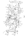
- FIGS. 1a ) and b) is in a side view ( Fig. 1a )) and front view ( Fig. 1b )) a pressing jaw 1 for producing a press connection is shown.
- the pressing jaw 1 has an upper pressing jaw half 2 pivotable about a first pivot axis X1 with an upper main inlet contour 2.1 and a lower pressing jaw half 3 pivotable about a second pivot axis X2 with a lower main inlet contour 3.1.
- the main inlet contour 2.1 and the main inlet contour 3.1 together with a drive element 12.1 in the form of a roller pair, which is part of a pressing jaw drive 12.
- the pressing jaw drive 12 or the drive element 12.1 here is hydraulically movable in a direction from the rear to the front pressing jaw end (shown by an arrow) and thereby pushes the pressing jaw halves 2 and 3 apart at the rear end of the pressing jaw, whereby the pressing jaw halves at the front end, the means the press mouth to move towards each other or close.
- the pressing jaw 1 also has an upper contour element 4 with an upper auxiliary inlet contour 4.1 and a lower contour element 5 with a lower auxiliary inlet contour 5.1.
- the upper contour element 4 interacts with the upper pressing jaw half 2 such that a movement of the upper contour element 4 on the upper pressing jaw half 2 transfers.
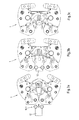
- the upper die jaw half 2 and the lower die jaw half 3 are, like the FIGS. 3a ) to g), from an open position ( Fig. 3a )) via an intermediate position ( FIGS. 3b ) to e)) in a closed position ( Fig. 3g )).
- the upper auxiliary inlet contour 4.1 is displaceable relative to the upper main inlet contour 2.1 and the lower auxiliary inlet contour 5.1 relative to the lower main inlet contour 3.1, as will be described in more detail below.
- FIGS. 3a ) and b) shows how a first stroke is carried out from the open position to the intermediate position, in that the pressing jaw drive 12 moves the roller-containing drive element 12.1 along the main inlet contours 2.1 and 3.1.
- the Figures 3c ) to e) then show how in the intermediate position the additional infeed contours 4.1 and 5.1 are displaced from an inactive to an active position in which they partially cover the respective main inlet contour 2.1 or 3.1 towards the rear end of the press jaw and protrude into the effective region of the drive element 12.1 , For the switching from the inactive to the active position of the pressing jaw drive 12 is first moved back to the starting position, which he in Fig. 3a ) has originally taken.
- the pressing jaw drive 12 is actuated again, whereby the pressing jaw halves 2 and 3 a second stroke of the Perform intermediate position in the closed position, which in the FIGS. 3e ) to g) is shown.
- the opening angle of the press jaw is 0 °.
- the pressing jaw 1 has a first synchronization plate 6 and a second synchronization plate 7.
- the first synchronization plate 6 is firmly screwed to the upper contour element 4, in such a way that a movement of the first synchronization plate 6 transmits to the upper contour element 4.
- the second synchronization plate 7 is connected to the lower contour element 5.
- the first synchronization plate 6 and the second synchronization plate 7 are movable relative to both the upper and lower die jaws 2 and 3, respectively.
- a guide slot 6.1 or 7.1 is respectively formed as a synchronization contour, which cooperates with a guide pin 8a and 8b as a guide counterpart.
- the guide pin 8a or 8b is anchored to that pressing jaw half 2 or 3, which is adjacent to the respective guide slot 6.1 or 7.1 in the transverse direction X.
- a first guide slot 2.2 or 3.2 and a second guide slot 2.3 or 3.3 are respectively formed in the two die jaw halves 2 and 3.
- the guide slot 2.2 acts with a guide pin 10 a and the Guide slot 3.2 with a guide pin 10b together.
- the further guide slot 2.3 cooperates with a further guide pin 9a and the further guide slot 3.3 with a guide pin 9b.
- the guide pins are all anchored to those synchronization plate 6 and 7, which is adjacent in the transverse direction X to the associated guide slot 2.2, 2.3, 3.2, 3.3.
- the two guide pins 10a and 10b are further provided with gripping pieces 11a and 11b, with which the bolts 10a and 10b can be displaced in the guide slot 2.2 or 3.2.
- the upper die jaw half 2 and the lower die jaw half 3 are arranged in the open position to each other so that the upper and lower main inlet contour 2.1 and 3.1 in the effective range and the upper and lower additional inlet contour 4.1 and 5.1 outside the effective range of the drive element 12.1 of the pressing jaw drive 12 is located.
- the upper and lower pressing jaw halves 2 and 3 are arranged such that the upper and lower main inlet contours 2.1 and 3.1 are outside the effective range and the upper and lower auxiliary inlet contours 4.1 and 5.1 are within the effective range of the drive element 12.1.
- the two pressing jaw halves 2 and 3 and the synchronization plates 6 and 7 are arranged and shaped so that the pressing jaw halves 2 and 3 must be arranged in the intermediate position already mentioned, so that the synchronization plates 6 and 7 respectively relative to the pressing jaw halves. 2 and 3 can be moved. In any other position than the intermediate position, the synchronization plates 6 and 7, which are rotationally symmetrical and arranged here, blocked.
- the press jaw halves 2 and 3 each consist of a pair of plates, which in turn each in the transverse direction X next to each other and spaced apart plates 2a and 2b or 3a and 3b, which have the same shape.
- the pressing jaw halves 2 and 3 formed in this way are held together by side plates 13a and 13b, which in turn serve to receive two main bolts 14a and 14b, on which ultimately the pressing jaw halves 2 and 3 are pivotally mounted.
- a so-called locking pin 16a and 16b shown each jaw half 2 and 3, with whose help the pressing jaw halves 2 and 3 are blocked in the intermediate position.
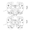
- the locking mechanism realized thereby is described below with reference to Fig. 4 explained.
- a locking mechanism blocks or blocks the opening of the pressing jaw 1 between the first stroke and the second stroke, so that the operator does not remove the pressing jaw 1 or break off the pressing can.
- the locking mechanism has four switch positions held in Fig. 4 , Figure 11 are shown and can be stabilized by a resilient ball pressure piece.
- the locking pin 16a can be switched in the axial direction y s and in the direction of the slot 20 in the hollow bolt 17a. At the beginning, the locking pin 16a is in the in Fig. 4 1 immersed in the side plate 2 a and is connected with increasing closing movement by the guide groove 18 a in the side plate 2 a in the axial direction y s in the opposite side plate 2 b Fig.
Landscapes
- Engineering & Computer Science (AREA)
- Mechanical Engineering (AREA)
- Press Drives And Press Lines (AREA)
- Clamps And Clips (AREA)
- Supply, Installation And Extraction Of Printed Sheets Or Plates (AREA)
- Mounting, Exchange, And Manufacturing Of Dies (AREA)
Applications Claiming Priority (1)
| Application Number | Priority Date | Filing Date | Title |
|---|---|---|---|
| DE102011100965A DE102011100965B4 (de) | 2011-05-09 | 2011-05-09 | Pressbacke und Verfahren zum Herstellen einer Pressverbindung |
Publications (3)
| Publication Number | Publication Date |
|---|---|
| EP2522464A2 true EP2522464A2 (fr) | 2012-11-14 |
| EP2522464A3 EP2522464A3 (fr) | 2013-11-27 |
| EP2522464B1 EP2522464B1 (fr) | 2015-05-27 |
Family
ID=45531781
Family Applications (1)
| Application Number | Title | Priority Date | Filing Date |
|---|---|---|---|
| EP12152832.7A Active EP2522464B1 (fr) | 2011-05-09 | 2012-01-27 | Mordache et procédé de fabrication d'un emmanchement par pressage |
Country Status (4)
| Country | Link |
|---|---|
| US (1) | US10179398B2 (fr) |
| EP (1) | EP2522464B1 (fr) |
| DE (1) | DE102011100965B4 (fr) |
| DK (1) | DK2522464T3 (fr) |
Cited By (1)
| Publication number | Priority date | Publication date | Assignee | Title |
|---|---|---|---|---|
| US10421164B2 (en) | 2016-02-19 | 2019-09-24 | Viega Technology Gmbh & Co. Kg | Device and method for transmitting a mechanical force for driving a pressing device for press fittings |
Families Citing this family (4)
| Publication number | Priority date | Publication date | Assignee | Title |
|---|---|---|---|---|
| CA2989776A1 (fr) * | 2015-07-29 | 2017-02-02 | Aydin OZKAN | Machine de prehension |
| US10197746B2 (en) * | 2015-12-18 | 2019-02-05 | US Conec, Ltd | Fiber optic ferrule and a guide pin clamp with field changeable guide pins |
| CN107175598B (zh) * | 2017-06-28 | 2019-01-01 | 安徽江淮车轮有限公司 | 一种自动锁紧的高稳定性汽车轮毂固定装置 |
| DE102021105243B4 (de) | 2021-03-04 | 2022-10-13 | Novopress Gmbh Pressen Und Presswerkzeuge & Co. Kg | Presswerkzeug |
Family Cites Families (12)
| Publication number | Priority date | Publication date | Assignee | Title |
|---|---|---|---|---|
| US2766631A (en) * | 1950-06-09 | 1956-10-16 | Rotor Tool Company | Power multiplying mechanism for portable hand tools |
| DE2844475C2 (de) | 1978-10-12 | 1983-09-29 | Peter Ing.(grad.) 6380 Bad Homburg Schröck | Radialpresse für Werkstücke mit zylindrischer Außenfläche |
| DE29703053U1 (de) * | 1997-02-21 | 1997-04-10 | Novopress GmbH Pressen und Presswerkzeuge & Co KG, 41460 Neuss | Preßgerät |
| US6079896A (en) * | 1998-01-07 | 2000-06-27 | Isi Norgren, Inc. | Clamp with improved internal cam action |
| DE19950706C2 (de) * | 1999-10-21 | 2002-10-02 | Smw Autoblok Spannsysteme Gmbh | Aufspanneinrichtung |
| DE10029761C1 (de) * | 2000-06-16 | 2001-10-31 | Mapress Gmbh & Co Kg | Verfahren zur Herstellung einer Rohrpressverbindung |
| US6553870B1 (en) * | 2000-11-17 | 2003-04-29 | Lawrence G. Kendall | Container holder with sink drain attachment |
| DE10101440B4 (de) * | 2001-01-15 | 2017-10-26 | REMS-WERK Christian Föll und Söhne GmbH & Co. | Preßzange |
| US7121166B2 (en) * | 2004-04-29 | 2006-10-17 | National-Oilwell, L.P. | Power tong assembly |
| US20080216543A1 (en) | 2004-11-24 | 2008-09-11 | Hamm James E | Enhanced Press Apparatus |
| DE502007005286D1 (de) * | 2007-11-08 | 2010-11-18 | Schunk Gmbh & Co Kg | Lünette |
| US8474806B2 (en) * | 2009-01-26 | 2013-07-02 | T&T Engineering Services, Inc. | Pipe gripping apparatus |
-
2011
- 2011-05-09 DE DE102011100965A patent/DE102011100965B4/de active Active
-
2012
- 2012-01-27 EP EP12152832.7A patent/EP2522464B1/fr active Active
- 2012-01-27 DK DK12152832.7T patent/DK2522464T3/en active
- 2012-04-17 US US13/449,021 patent/US10179398B2/en active Active
Non-Patent Citations (1)
| Title |
|---|
| None |
Cited By (1)
| Publication number | Priority date | Publication date | Assignee | Title |
|---|---|---|---|---|
| US10421164B2 (en) | 2016-02-19 | 2019-09-24 | Viega Technology Gmbh & Co. Kg | Device and method for transmitting a mechanical force for driving a pressing device for press fittings |
Also Published As
| Publication number | Publication date |
|---|---|
| EP2522464B1 (fr) | 2015-05-27 |
| US10179398B2 (en) | 2019-01-15 |
| DE102011100965B4 (de) | 2013-02-28 |
| DE102011100965A1 (de) | 2012-11-15 |
| US20120284990A1 (en) | 2012-11-15 |
| EP2522464A3 (fr) | 2013-11-27 |
| DK2522464T3 (en) | 2015-08-31 |
Similar Documents
| Publication | Publication Date | Title |
|---|---|---|
| EP0468335B1 (fr) | Outil pour le sertissage d'un connecteur à un conducteur et une isolation | |
| DE19963097C5 (de) | Zange zum Verpressen eines Werkstücks | |
| DE602004001408T2 (de) | Befestigungseinrichtung zum Montieren und Entfernen eines Biegewerkzeugs | |
| EP2522464B1 (fr) | Mordache et procédé de fabrication d'un emmanchement par pressage | |
| EP2450149B1 (fr) | Outil doté de zones actives différentes | |
| EP2794142B1 (fr) | Matrice d'un dispositif de poinçonnage et procédé de poinçonnage | |
| EP1336440B1 (fr) | Dispositif pour le mouvement des pièces avec des barres d'amenage | |
| DE69832426T2 (de) | Pressvorrichtung für Metallblech | |
| EP1171260B1 (fr) | Dispositif pour la division par rupture d'une piece | |
| DE212011100163U1 (de) | Vorrichtung zum Bruchtrennen einer Pleuelstange | |
| DE102014104146B4 (de) | Stanze | |
| EP2497580A1 (fr) | Outil de pliage et agencement d'outil de pliage | |
| EP2176022A1 (fr) | Dispositif de serrage et agencement d'un tel dispositif de serrage avec une pince de serrage | |
| EP3302843B1 (fr) | Outil de pliage pour presse plieuse | |
| DE102014019815B3 (de) | Formsteinverlegevorrichtung mit längenveränderbarem Verschiebeelement | |
| DE10063154B4 (de) | Schmiedepresse mit Stellvorrichtung auf Matrizenseite | |
| EP1767313A2 (fr) | Outil de sertissage | |
| DE2646133A1 (de) | Keilantriebsmechanismus | |
| AT512706B1 (de) | Verfahren zur Stanzung von zwei übereinander angeordneten, auf einer Seite miteinander verbundenen flachen Teilstücken eines Werkstückes sowie Vorrichtung zur Durchführung des Verfahrens | |
| AT517315B1 (de) | Verfahren zum Verstellen eines Formabschnittes eines Biegewerkzeuges | |
| DE3876152T2 (de) | Blechtiefziehvorrichtung. | |
| WO2014032921A1 (fr) | Dispositif d'usinage d'objets allongés | |
| EP0882531A2 (fr) | Dispositif d'usinage, en particulier pince à sertir | |
| DE2229520C3 (de) | Einrichtung zum automatischen Prägestempeln von Walzgut | |
| DE102020129789A1 (de) | Kompaktiertechnik und Kompaktierfügetechnik |
Legal Events
| Date | Code | Title | Description |
|---|---|---|---|
| PUAI | Public reference made under article 153(3) epc to a published international application that has entered the european phase |
Free format text: ORIGINAL CODE: 0009012 |
|
| AK | Designated contracting states |
Kind code of ref document: A2 Designated state(s): AL AT BE BG CH CY CZ DE DK EE ES FI FR GB GR HR HU IE IS IT LI LT LU LV MC MK MT NL NO PL PT RO RS SE SI SK SM TR |
|
| AX | Request for extension of the european patent |
Extension state: BA ME |
|
| PUAL | Search report despatched |
Free format text: ORIGINAL CODE: 0009013 |
|
| AK | Designated contracting states |
Kind code of ref document: A3 Designated state(s): AL AT BE BG CH CY CZ DE DK EE ES FI FR GB GR HR HU IE IS IT LI LT LU LV MC MK MT NL NO PL PT RO RS SE SI SK SM TR |
|
| AX | Request for extension of the european patent |
Extension state: BA ME |
|
| RIC1 | Information provided on ipc code assigned before grant |
Ipc: B25B 27/10 20060101AFI20131021BHEP |
|
| 17P | Request for examination filed |
Effective date: 20131211 |
|
| RBV | Designated contracting states (corrected) |
Designated state(s): AL AT BE BG CH CY CZ DE DK EE ES FI FR GB GR HR HU IE IS IT LI LT LU LV MC MK MT NL NO PL PT RO RS SE SI SK SM TR |
|
| 17Q | First examination report despatched |
Effective date: 20140227 |
|
| GRAP | Despatch of communication of intention to grant a patent |
Free format text: ORIGINAL CODE: EPIDOSNIGR1 |
|
| INTG | Intention to grant announced |
Effective date: 20150121 |
|
| GRAS | Grant fee paid |
Free format text: ORIGINAL CODE: EPIDOSNIGR3 |
|
| GRAA | (expected) grant |
Free format text: ORIGINAL CODE: 0009210 |
|
| AK | Designated contracting states |
Kind code of ref document: B1 Designated state(s): AL AT BE BG CH CY CZ DE DK EE ES FI FR GB GR HR HU IE IS IT LI LT LU LV MC MK MT NL NO PL PT RO RS SE SI SK SM TR |
|
| REG | Reference to a national code |
Ref country code: GB Ref legal event code: FG4D Free format text: NOT ENGLISH |
|
| REG | Reference to a national code |
Ref country code: CH Ref legal event code: EP |
|
| REG | Reference to a national code |
Ref country code: AT Ref legal event code: REF Ref document number: 728575 Country of ref document: AT Kind code of ref document: T Effective date: 20150615 |
|
| REG | Reference to a national code |
Ref country code: CH Ref legal event code: NV Representative=s name: TROESCH SCHEIDEGGER WERNER AG, CH |
|
| REG | Reference to a national code |
Ref country code: IE Ref legal event code: FG4D Free format text: LANGUAGE OF EP DOCUMENT: GERMAN |
|
| REG | Reference to a national code |
Ref country code: DE Ref legal event code: R096 Ref document number: 502012003264 Country of ref document: DE Effective date: 20150709 |
|
| REG | Reference to a national code |
Ref country code: NL Ref legal event code: T3 |
|
| REG | Reference to a national code |
Ref country code: DK Ref legal event code: T3 Effective date: 20150827 |
|
| REG | Reference to a national code |
Ref country code: LT Ref legal event code: MG4D |
|
| PG25 | Lapsed in a contracting state [announced via postgrant information from national office to epo] |
Ref country code: NO Free format text: LAPSE BECAUSE OF FAILURE TO SUBMIT A TRANSLATION OF THE DESCRIPTION OR TO PAY THE FEE WITHIN THE PRESCRIBED TIME-LIMIT Effective date: 20150827 Ref country code: ES Free format text: LAPSE BECAUSE OF FAILURE TO SUBMIT A TRANSLATION OF THE DESCRIPTION OR TO PAY THE FEE WITHIN THE PRESCRIBED TIME-LIMIT Effective date: 20150527 Ref country code: PT Free format text: LAPSE BECAUSE OF FAILURE TO SUBMIT A TRANSLATION OF THE DESCRIPTION OR TO PAY THE FEE WITHIN THE PRESCRIBED TIME-LIMIT Effective date: 20150928 Ref country code: FI Free format text: LAPSE BECAUSE OF FAILURE TO SUBMIT A TRANSLATION OF THE DESCRIPTION OR TO PAY THE FEE WITHIN THE PRESCRIBED TIME-LIMIT Effective date: 20150527 Ref country code: HR Free format text: LAPSE BECAUSE OF FAILURE TO SUBMIT A TRANSLATION OF THE DESCRIPTION OR TO PAY THE FEE WITHIN THE PRESCRIBED TIME-LIMIT Effective date: 20150527 Ref country code: LT Free format text: LAPSE BECAUSE OF FAILURE TO SUBMIT A TRANSLATION OF THE DESCRIPTION OR TO PAY THE FEE WITHIN THE PRESCRIBED TIME-LIMIT Effective date: 20150527 |
|
| PG25 | Lapsed in a contracting state [announced via postgrant information from national office to epo] |
Ref country code: BG Free format text: LAPSE BECAUSE OF FAILURE TO SUBMIT A TRANSLATION OF THE DESCRIPTION OR TO PAY THE FEE WITHIN THE PRESCRIBED TIME-LIMIT Effective date: 20150827 Ref country code: IS Free format text: LAPSE BECAUSE OF FAILURE TO SUBMIT A TRANSLATION OF THE DESCRIPTION OR TO PAY THE FEE WITHIN THE PRESCRIBED TIME-LIMIT Effective date: 20150927 Ref country code: GR Free format text: LAPSE BECAUSE OF FAILURE TO SUBMIT A TRANSLATION OF THE DESCRIPTION OR TO PAY THE FEE WITHIN THE PRESCRIBED TIME-LIMIT Effective date: 20150828 Ref country code: RS Free format text: LAPSE BECAUSE OF FAILURE TO SUBMIT A TRANSLATION OF THE DESCRIPTION OR TO PAY THE FEE WITHIN THE PRESCRIBED TIME-LIMIT Effective date: 20150527 Ref country code: LV Free format text: LAPSE BECAUSE OF FAILURE TO SUBMIT A TRANSLATION OF THE DESCRIPTION OR TO PAY THE FEE WITHIN THE PRESCRIBED TIME-LIMIT Effective date: 20150527 |
|
| REG | Reference to a national code |
Ref country code: FR Ref legal event code: PLFP Year of fee payment: 5 |
|
| PG25 | Lapsed in a contracting state [announced via postgrant information from national office to epo] |
Ref country code: EE Free format text: LAPSE BECAUSE OF FAILURE TO SUBMIT A TRANSLATION OF THE DESCRIPTION OR TO PAY THE FEE WITHIN THE PRESCRIBED TIME-LIMIT Effective date: 20150527 |
|
| PG25 | Lapsed in a contracting state [announced via postgrant information from national office to epo] |
Ref country code: RO Free format text: LAPSE BECAUSE OF NON-PAYMENT OF DUE FEES Effective date: 20150527 Ref country code: CZ Free format text: LAPSE BECAUSE OF FAILURE TO SUBMIT A TRANSLATION OF THE DESCRIPTION OR TO PAY THE FEE WITHIN THE PRESCRIBED TIME-LIMIT Effective date: 20150527 Ref country code: PL Free format text: LAPSE BECAUSE OF FAILURE TO SUBMIT A TRANSLATION OF THE DESCRIPTION OR TO PAY THE FEE WITHIN THE PRESCRIBED TIME-LIMIT Effective date: 20150527 Ref country code: SK Free format text: LAPSE BECAUSE OF FAILURE TO SUBMIT A TRANSLATION OF THE DESCRIPTION OR TO PAY THE FEE WITHIN THE PRESCRIBED TIME-LIMIT Effective date: 20150527 |
|
| REG | Reference to a national code |
Ref country code: DE Ref legal event code: R097 Ref document number: 502012003264 Country of ref document: DE |
|
| PLBE | No opposition filed within time limit |
Free format text: ORIGINAL CODE: 0009261 |
|
| STAA | Information on the status of an ep patent application or granted ep patent |
Free format text: STATUS: NO OPPOSITION FILED WITHIN TIME LIMIT |
|
| 26N | No opposition filed |
Effective date: 20160301 |
|
| PG25 | Lapsed in a contracting state [announced via postgrant information from national office to epo] |
Ref country code: SI Free format text: LAPSE BECAUSE OF FAILURE TO SUBMIT A TRANSLATION OF THE DESCRIPTION OR TO PAY THE FEE WITHIN THE PRESCRIBED TIME-LIMIT Effective date: 20150527 |
|
| PG25 | Lapsed in a contracting state [announced via postgrant information from national office to epo] |
Ref country code: LU Free format text: LAPSE BECAUSE OF FAILURE TO SUBMIT A TRANSLATION OF THE DESCRIPTION OR TO PAY THE FEE WITHIN THE PRESCRIBED TIME-LIMIT Effective date: 20160127 |
|
| GBPC | Gb: european patent ceased through non-payment of renewal fee |
Effective date: 20160127 |
|
| PG25 | Lapsed in a contracting state [announced via postgrant information from national office to epo] |
Ref country code: MC Free format text: LAPSE BECAUSE OF FAILURE TO SUBMIT A TRANSLATION OF THE DESCRIPTION OR TO PAY THE FEE WITHIN THE PRESCRIBED TIME-LIMIT Effective date: 20150527 |
|
| PG25 | Lapsed in a contracting state [announced via postgrant information from national office to epo] |
Ref country code: GB Free format text: LAPSE BECAUSE OF NON-PAYMENT OF DUE FEES Effective date: 20160127 |
|
| REG | Reference to a national code |
Ref country code: IE Ref legal event code: MM4A |
|
| REG | Reference to a national code |
Ref country code: FR Ref legal event code: PLFP Year of fee payment: 6 |
|
| PG25 | Lapsed in a contracting state [announced via postgrant information from national office to epo] |
Ref country code: IE Free format text: LAPSE BECAUSE OF NON-PAYMENT OF DUE FEES Effective date: 20160127 |
|
| REG | Reference to a national code |
Ref country code: DE Ref legal event code: R082 Ref document number: 502012003264 Country of ref document: DE Representative=s name: COHAUSZ & FLORACK PATENT- UND RECHTSANWAELTE P, DE Ref country code: DE Ref legal event code: R081 Ref document number: 502012003264 Country of ref document: DE Owner name: VIEGA TECHNOLOGY GMBH & CO. KG, DE Free format text: FORMER OWNER: VIEGA GMBH & CO. KG, 57439 ATTENDORN, DE |
|
| REG | Reference to a national code |
Ref country code: AT Ref legal event code: PC Ref document number: 728575 Country of ref document: AT Kind code of ref document: T Owner name: VIEGA TECHNOLOGY GMBH & CO. KG, DE Effective date: 20170512 |
|
| PG25 | Lapsed in a contracting state [announced via postgrant information from national office to epo] |
Ref country code: SE Free format text: LAPSE BECAUSE OF FAILURE TO SUBMIT A TRANSLATION OF THE DESCRIPTION OR TO PAY THE FEE WITHIN THE PRESCRIBED TIME-LIMIT Effective date: 20150527 |
|
| REG | Reference to a national code |
Ref country code: NL Ref legal event code: PD Owner name: VIEGA TECHNOLOGY GMBH & CO. KG; DE Free format text: DETAILS ASSIGNMENT: CHANGE OF OWNER(S), ASSIGNMENT; FORMER OWNER NAME: VIEGA GMBH & CO. KG Effective date: 20170412 |
|
| PG25 | Lapsed in a contracting state [announced via postgrant information from national office to epo] |
Ref country code: MT Free format text: LAPSE BECAUSE OF FAILURE TO SUBMIT A TRANSLATION OF THE DESCRIPTION OR TO PAY THE FEE WITHIN THE PRESCRIBED TIME-LIMIT Effective date: 20150527 |
|
| REG | Reference to a national code |
Ref country code: FR Ref legal event code: TP Owner name: VIEGA TECHNOLOGY GMBH & CO. KG, DE Effective date: 20171013 |
|
| REG | Reference to a national code |
Ref country code: FR Ref legal event code: PLFP Year of fee payment: 7 |
|
| REG | Reference to a national code |
Ref country code: CH Ref legal event code: PUE Owner name: VIEGA TECHNOLOGY GMBH AND CO. KG, DE Free format text: FORMER OWNER: VIEGA GMBH AND CO. KG, DE |
|
| PG25 | Lapsed in a contracting state [announced via postgrant information from national office to epo] |
Ref country code: HU Free format text: LAPSE BECAUSE OF FAILURE TO SUBMIT A TRANSLATION OF THE DESCRIPTION OR TO PAY THE FEE WITHIN THE PRESCRIBED TIME-LIMIT; INVALID AB INITIO Effective date: 20120127 Ref country code: CY Free format text: LAPSE BECAUSE OF FAILURE TO SUBMIT A TRANSLATION OF THE DESCRIPTION OR TO PAY THE FEE WITHIN THE PRESCRIBED TIME-LIMIT Effective date: 20150527 Ref country code: SM Free format text: LAPSE BECAUSE OF FAILURE TO SUBMIT A TRANSLATION OF THE DESCRIPTION OR TO PAY THE FEE WITHIN THE PRESCRIBED TIME-LIMIT Effective date: 20150527 |
|
| PG25 | Lapsed in a contracting state [announced via postgrant information from national office to epo] |
Ref country code: MK Free format text: LAPSE BECAUSE OF FAILURE TO SUBMIT A TRANSLATION OF THE DESCRIPTION OR TO PAY THE FEE WITHIN THE PRESCRIBED TIME-LIMIT Effective date: 20150527 Ref country code: TR Free format text: LAPSE BECAUSE OF FAILURE TO SUBMIT A TRANSLATION OF THE DESCRIPTION OR TO PAY THE FEE WITHIN THE PRESCRIBED TIME-LIMIT Effective date: 20150527 |
|
| PG25 | Lapsed in a contracting state [announced via postgrant information from national office to epo] |
Ref country code: AL Free format text: LAPSE BECAUSE OF FAILURE TO SUBMIT A TRANSLATION OF THE DESCRIPTION OR TO PAY THE FEE WITHIN THE PRESCRIBED TIME-LIMIT Effective date: 20150527 |
|
| PGFP | Annual fee paid to national office [announced via postgrant information from national office to epo] |
Ref country code: DK Payment date: 20220127 Year of fee payment: 11 Ref country code: AT Payment date: 20220125 Year of fee payment: 11 |
|
| PGFP | Annual fee paid to national office [announced via postgrant information from national office to epo] |
Ref country code: BE Payment date: 20220124 Year of fee payment: 11 |
|
| REG | Reference to a national code |
Ref country code: DK Ref legal event code: EBP Effective date: 20230131 |
|
| REG | Reference to a national code |
Ref country code: AT Ref legal event code: MM01 Ref document number: 728575 Country of ref document: AT Kind code of ref document: T Effective date: 20230127 |
|
| REG | Reference to a national code |
Ref country code: BE Ref legal event code: MM Effective date: 20230131 |
|
| PG25 | Lapsed in a contracting state [announced via postgrant information from national office to epo] |
Ref country code: AT Free format text: LAPSE BECAUSE OF NON-PAYMENT OF DUE FEES Effective date: 20230127 |
|
| PG25 | Lapsed in a contracting state [announced via postgrant information from national office to epo] |
Ref country code: BE Free format text: LAPSE BECAUSE OF NON-PAYMENT OF DUE FEES Effective date: 20230131 |
|
| PG25 | Lapsed in a contracting state [announced via postgrant information from national office to epo] |
Ref country code: DK Free format text: LAPSE BECAUSE OF NON-PAYMENT OF DUE FEES Effective date: 20230131 |
|
| PGFP | Annual fee paid to national office [announced via postgrant information from national office to epo] |
Ref country code: NL Payment date: 20250122 Year of fee payment: 14 |
|
| PGFP | Annual fee paid to national office [announced via postgrant information from national office to epo] |
Ref country code: CH Payment date: 20250201 Year of fee payment: 14 |
|
| PGFP | Annual fee paid to national office [announced via postgrant information from national office to epo] |
Ref country code: FR Payment date: 20250122 Year of fee payment: 14 |
|
| PGFP | Annual fee paid to national office [announced via postgrant information from national office to epo] |
Ref country code: IT Payment date: 20250123 Year of fee payment: 14 |
|
| PGFP | Annual fee paid to national office [announced via postgrant information from national office to epo] |
Ref country code: DE Payment date: 20260126 Year of fee payment: 15 |