EP2532464A2 - Machine à électroérosion à fil pour pièce inclinée - Google Patents
Machine à électroérosion à fil pour pièce inclinée Download PDFInfo
- Publication number
- EP2532464A2 EP2532464A2 EP12157434A EP12157434A EP2532464A2 EP 2532464 A2 EP2532464 A2 EP 2532464A2 EP 12157434 A EP12157434 A EP 12157434A EP 12157434 A EP12157434 A EP 12157434A EP 2532464 A2 EP2532464 A2 EP 2532464A2
- Authority
- EP
- European Patent Office
- Prior art keywords
- machining
- workpiece
- taper
- wire electrode
- angle
- Prior art date
- Legal status (The legal status is an assumption and is not a legal conclusion. Google has not performed a legal analysis and makes no representation as to the accuracy of the status listed.)
- Granted
Links
Images


Classifications
-
- B—PERFORMING OPERATIONS; TRANSPORTING
- B23—MACHINE TOOLS; METAL-WORKING NOT OTHERWISE PROVIDED FOR
- B23H—WORKING OF METAL BY THE ACTION OF A HIGH CONCENTRATION OF ELECTRIC CURRENT ON A WORKPIECE USING AN ELECTRODE WHICH TAKES THE PLACE OF A TOOL; SUCH WORKING COMBINED WITH OTHER FORMS OF WORKING OF METAL
- B23H7/00—Processes or apparatus applicable to both electrical discharge machining and electrochemical machining
- B23H7/14—Electric circuits specially adapted therefor, e.g. power supply
- B23H7/20—Electric circuits specially adapted therefor, e.g. power supply for program control, e.g. adaptive
-
- B—PERFORMING OPERATIONS; TRANSPORTING
- B23—MACHINE TOOLS; METAL-WORKING NOT OTHERWISE PROVIDED FOR
- B23H—WORKING OF METAL BY THE ACTION OF A HIGH CONCENTRATION OF ELECTRIC CURRENT ON A WORKPIECE USING AN ELECTRODE WHICH TAKES THE PLACE OF A TOOL; SUCH WORKING COMBINED WITH OTHER FORMS OF WORKING OF METAL
- B23H7/00—Processes or apparatus applicable to both electrical discharge machining and electrochemical machining
- B23H7/02—Wire-cutting
- B23H7/06—Control of the travel curve of the relative movement between electrode and workpiece
-
- G—PHYSICS
- G05—CONTROLLING; REGULATING
- G05B—CONTROL OR REGULATING SYSTEMS IN GENERAL; FUNCTIONAL ELEMENTS OF SUCH SYSTEMS; MONITORING OR TESTING ARRANGEMENTS FOR SUCH SYSTEMS OR ELEMENTS
- G05B19/00—Program-control systems
- G05B19/02—Program-control systems electric
- G05B19/18—Numerical control [NC], i.e. automatically operating machines, in particular machine tools, e.g. in a manufacturing environment, so as to execute positioning, movement or co-ordinated operations by means of program data in numerical form
- G05B19/408—Numerical control [NC], i.e. automatically operating machines, in particular machine tools, e.g. in a manufacturing environment, so as to execute positioning, movement or co-ordinated operations by means of program data in numerical form characterised by data handling or data format, e.g. reading, buffering or conversion of data
- G05B19/4086—Coordinate conversions; Other special calculations
-
- B—PERFORMING OPERATIONS; TRANSPORTING
- B23—MACHINE TOOLS; METAL-WORKING NOT OTHERWISE PROVIDED FOR
- B23H—WORKING OF METAL BY THE ACTION OF A HIGH CONCENTRATION OF ELECTRIC CURRENT ON A WORKPIECE USING AN ELECTRODE WHICH TAKES THE PLACE OF A TOOL; SUCH WORKING COMBINED WITH OTHER FORMS OF WORKING OF METAL
- B23H1/00—Electrical discharge machining, i.e. removing metal with a series of rapidly recurring electrical discharges between an electrode and a workpiece in the presence of a fluid dielectric
-
- B—PERFORMING OPERATIONS; TRANSPORTING
- B23—MACHINE TOOLS; METAL-WORKING NOT OTHERWISE PROVIDED FOR
- B23H—WORKING OF METAL BY THE ACTION OF A HIGH CONCENTRATION OF ELECTRIC CURRENT ON A WORKPIECE USING AN ELECTRODE WHICH TAKES THE PLACE OF A TOOL; SUCH WORKING COMBINED WITH OTHER FORMS OF WORKING OF METAL
- B23H11/00—Auxiliary apparatus or details, not otherwise provided for
- B23H11/003—Mounting of workpieces, e.g. working-tables
-
- G—PHYSICS
- G05—CONTROLLING; REGULATING
- G05B—CONTROL OR REGULATING SYSTEMS IN GENERAL; FUNCTIONAL ELEMENTS OF SUCH SYSTEMS; MONITORING OR TESTING ARRANGEMENTS FOR SUCH SYSTEMS OR ELEMENTS
- G05B2219/00—Program-control systems
- G05B2219/30—Nc systems
- G05B2219/33—Director till display
- G05B2219/33263—Conversion, transformation of coordinates, cartesian or polar
Definitions
- the present invention relates to a wire electric discharge machine, and more particularly, to a wire electric discharge machine for taper-machining a tilted workpiece.
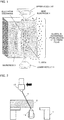
- a voltage is applied to a wire electrode 4 stretched between an upper wire guide 12 in an upper nozzle 10 and a lower wire guide 13 in a lower nozzle 11, and a workpiece 3 fixed on a workpiece table 1, which is driven relative to the wire electrode 4, is moved along two axes, X- and Y-axes (not shown), which perpendicularly intersect each other on a horizontal plane.
- Grooving is performed to obtain a desired machining shape by melting and removing the workpiece 3 by continuous electric discharge caused (in a machining gap) between the wire electrode 4 and the workpiece 3.
- the workpiece 3 thus melted and removed is reduced to sludge, which is discharged from a groove by a working fluid ejected from the upper and lower nozzles 10 and 11.
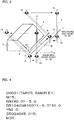
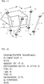
- FIG. 3 An example of conventional taper machining will be described with reference to FIGS. 2 to 5 .
- a member having a 45-degree slope is cut out of a cuboid workpiece.
- the horizontal position (XY-position) of the upper wire guide 12 relative to the lower wire guide 13 is shifted so that the wire electrode 4 is stretched obliquely relative to a workpiece mounting surface (not shown).
- This taper machining is a well-known method used to obtain a conical or quadrangular pyramidal shape or some other shape with arbitrary slopes.
- the amount of movement of the upper wire guide 12 relative to the lower wire guide 13 can be determined by calculation.
- the upper and lower wire guides are formed of members called “die guides” or “wire die guides” having guide holes through which the wire electrode 4 is passed.
- a taper machining function is enabled by a command code M15, and a coordinate system for machining programs and a machining start point (0,-5) are set by G92.
- the wire electrode 4 is in a posture perpendicular to a table surface (XY-plane).
- G01X-5.0 the wire electrode 4 starts to move toward a point A.
- the posture of the wire electrode 4 starts to tilt to prepare for slope machining in the next block (linear block A-B shown in FIG. 3 ), in response to commanded G51 (command for a leftward tilt of the wire) and T45.0 (in which T is a command for a tilt angle of the wire electrode 4).
- the tilt angle of the wire electrode 4 becomes 45° when the point A is reached.
- the wire electrode 4 When Y60.0 is then commanded, the wire electrode 4 is kept at 45° on the left side with respect to the direction of movement as it starts and continues slope machining and advances to a point B. Finally, in response to a command X5.0, the wire electrode 4 starts to move toward a machining end point. The moment this movement is started, the tilt of the wire electrode 4 starts to be gradually restored to its original angle in response to commanded G50 (command for canceling the tilt of the wire electrode 4) and T0. When the wire electrode 4 reaches the machining end point, it is restored to its vertical state (with the tilt angle at 0°), whereupon the machining ends.
- FIG. 5 shows a program example (00002) for machining of the workpiece with the tapers of 45° and 25°.
- the taper machining function is enabled by the command code M15, and the coordinate system for the machining programs and the machining start point (0,-5) are set by G92.
- the wire electrode 4 is in a posture perpendicular to the table surface (XY-plane).
- the wire electrode 4 starts to move toward the point A.
- the posture of the wire electrode 4 starts to tilt to prepare for slope machining in the next block (linear block A-C shown in FIG. 5 ), in response to the commanded G51 and T45.0.
- the tilt angle of the wire electrode 4 becomes 45° when the point A is reached by the wire electrode 4.
- the wire electrode 4 When Y30.0 is then commanded, the wire electrode 4 is kept at 45° on the left side with respect to the direction of movement as it starts and continues slope machining and advances to a point C. When the wire electrode 4 reaches the point C, its tilt angle becomes 25° in response to a command T25.0. When Y30.0 is then commanded, the wire electrode 4 is kept at 25° with respect to the direction of movement as it starts and continues slope machining and advances to the point B. Finally, in response to the command X5.0, the wire electrode 4 starts to move toward the machining end point. The moment this movement is started, the tilt of the wire electrode 4 starts to be gradually restored to its original angle in response to the commanded G50 and T0. When the wire electrode 4 reaches the machining end point, its posture is restored to the vertical state (with the tilt angle at 0°), whereupon the machining ends.
- the necessary tilt angle of the wire electrode 4 for the execution of the taper machining corresponds to the tilt angle (taper angle) of a machined surface and is usually designated by a numerical value in a machining program.
- the position (relative XY-position) of the upper wire guide 12 relative to the lower wire guide 13 is shifted from a position where the wire guides 12 and 13 are vertically aligned to a position where the wire electrode 4 correctly extends along a plane with the programmed tilt.
- This movement of the wire electrode 4 is achieved by moving (along a U-axis parallel to the X-axis and a V-axis parallel to the Y-axis) a drive unit that supports one (e.g., upper wire guide 12) of the wire guides 12 and 13.
- the vertical position of the wire electrode is adjusted so that the wire electrode extends perpendicular to the workpiece.
- This technique is not designed to deliberately tilt the workpiece to be taper-machined so that the wire electrode extends substantially perpendicular to a table surface.
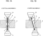
- the taper machining in which the wire electrode 4 supported by the wire guide portion is stretched obliquely by translating the upper wire guide 12 relative to the table surface involves more technical problems than vertical machining in which the wire electrode 4 is stretched vertically.
- the problems are as follows:
- the object of the present invention is to provide a wire electric discharge machine capable of performing taper machining in which a wire electrode is stretched vertically or substantially vertically to such a degree as to prevent or reduce adverse effects in the taper machining.
- the wire electric discharge machine is provided with a table having a flat surface and a coordinate system based on two orthogonal axes and adapted to carry a workpiece thereon and which performs electric discharge machining while relatively moving a wire electrode and the workpiece according to a machining program for taper machining.
- the wire electric discharge machine comprises: a mounting unit configured to mount the workpiece at an angle to the flat surface; a tilt angle setting unit configured to set a tilt angle of the workpiece, mounted on the mounting unit at an angle to the flat surface, with respect to the flat surface; a coordinate system transformation unit configured to transform the coordinate system by tilting the coordinate system based on the tilt angle set by the tilt angle setting unit; and a machining command value correction unit configured to correct a machining command value commanded by the machining program, based on the coordinate system transformed by the coordinate system transformation unit.
- the angle at which the workpiece is tilted relative to the flat surface by the mounting unit may be equal to or in the vicinity of the angle of a taper portion commanded by the machining program.
- the angle at which the workpiece is tilted relative to the flat surface by the mounting unit may be equal to or in the vicinity of an angle intermediate between maximum and minimum values of the taper angle.
- the mounting unit may be an adjustable-angle index machine, a rotary axis having an indexing and positioning function, or a fixing jig having a sine-bar structure.
- the wire electric discharge machine may further comprise a machining condition storage unit configured to store machining conditions prepared for each plate thickness of the workpiece, a plate thickness correction unit configured to correct the plate thickness of the workpiece based on the tilt angle set by the tilt angle setting unit, and a machining condition setting unit configured to set the machining conditions based on the plate thickness corrected by the plate thickness correction unit.
- a machining condition storage unit configured to store machining conditions prepared for each plate thickness of the workpiece
- a plate thickness correction unit configured to correct the plate thickness of the workpiece based on the tilt angle set by the tilt angle setting unit
- a machining condition setting unit configured to set the machining conditions based on the plate thickness corrected by the plate thickness correction unit.
- the machining command value correction unit may calculate an angle difference between a commanded taper angle and a current angle of the wire electrode on the coordinate system transformed by the coordinate system transformation unit, and a wire guide may be moved based on the calculated angle difference.
- a wire electric discharge machine capable of performing taper machining in which a wire electrode is stretched vertically or substantially vertically to such a degree as to prevent or reduce adverse effects in the taper machining.
- a workpiece is rotated as it is set in place, the position of the wire electrode is controlled so that a taper angle is an angle as commanded with respect to a direction perpendicular to the workpiece, and the rotation angle of the workpiece is made substantially equal to the commanded taper angle.
- the wire electrode can be kept substantially perpendicular to a table surface during the machining, so that conventional adverse effects in the taper machining can be avoided.
- a coordinate system for machining programs is transformed by correcting the parallelism of a workpiece 3 with respect to a plane defined by X-and Y-axes so that the wire electrode 4 extends perpendicular to the workpiece 3 mounted on at an arbitrary angle on a table surface, a machining command value is corrected based on the transformed coordinate system, and wire electric discharge machining is performed according to the corrected machining command value.
- machining command value is corrected based on the transformed coordinate system, and wire electric discharge machining is performed according to the corrected machining command value.
- the wire electric discharge machine is designed to perform taper machining based on the above technique. Specifically, the taper machining is performed in such a manner that the wire electrode 4 is stretched perpendicular or substantially perpendicular to the table surface to such a degree as to prevent or reduce adverse effects in the taper machining. In this state, the taper machining is performed with the workpiece 3 mounted obliquely relative to the table surface instead of tilting the wire electrode 4.
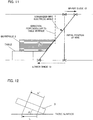
- FIG. 12 illustrates the amount of relative movement of the wire electrode 4 and the tilted workpiece 3.
- the table In the case where the workpiece 3 is mounted obliquely on the table surface, in contrast, the table must be moved with the amount of movement L' corrected to L according to equation (1) when L' is commanded by a machining program.
- FIG. 15 The taper machining performed by the wire electric discharge machine according to the present invention will now be described with reference to FIG. 15 .
- the workpiece 3 of FIG. 3 is rotated by 45° about the Y-axis, and a three-axis orthogonal coordinate system based on X'-, Y'-, and Z'-axes is newly provided in addition to the three-axis orthogonal coordinate system of FIG. 3 based on X-, Y-, and Z-axes.
- the Y'-axis is coincident with the Y-axis.
- the workpiece 3 is rotated about the Y-axis to be tilted at 45° from the table surface (XY-plane) of the machine.
- the linear block A-B having been conventionally machined as a 45° slope, as shown in FIG. 3 , is a surface perpendicular to the table surface in the case of the taper machining according to the present invention shown in FIG. 15 .
- This coordinate system can be transformed by only creating a machining program (00003) shown in FIG. 16 , which comprises G134W1 and G134W0 added to the conventional machining program (00001) shown in FIG. 4 .
- a coordinate system transformation function is enabled by the command G134W1.
- a coordinate system tilt angle is commanded by S.
- the X'Y'Z'-coordinate system for taper machining is set, and the wire electrode 4 is tilted perpendicular to an X'Y'-plane at the machining start point. Since S45.0 is given in this case, the coordinate system is tilted at 45°.
- wire electrode 4 becomes perpendicular to the X'Y'-plane, M15 is commanded so that the taper machining function is enabled, and the coordinate system for the machining programs and the machining start point (0,-5) are set by G92. At the machining start point, the wire electrode 4 extends perpendicular to the X'Y'-plane.
- the wire electrode 4 In response to the command G01X-5.0, the wire electrode 4 starts to move toward the point A. In response to G51 and T45.0 commanded at the same time with G01X-5.0, the posture of the wire electrode 4 starts to change so as to be perpendicular to the table surface (XY-plane) to prepare for machining in the next block (linear block A-B). When the point A is reached, the wire electrode 4 extends perpendicular to the table surface.
- the wire electrode 4 advances to the point B without changing its posture. Then, in response to a command X5.0, the wire electrode 4 starts to move toward the machining end point. In response to G50 and T0 commanded at the same time with X-5.0, the posture of the wire electrode 4 starts to be gradually restored so that it is perpendicular to the X'Y'-plane. When the machining end point is reached, the wire electrode 4 is restored to the state where it extends perpendicular to the X'Y'-plane.
- machining with a single taper angle is illustrated in the foregoing example for ease of description of the features of the present invention, machining with a plurality of taper angles, as shown in FIG. 5 , should be performed as follows.
- the wire electrode 4 being machined cannot maintain a completely vertical state, it is evident that efficient and precise machining can be achieved under less influence of the problems (I) to (V) than the conventional taper machining in which the wire electrode 4 can be tilted to the maximum angle of 45°.
- a linear block A-C having been conventionally machined as a 45° slope is a surface tilted at 10° from a plane perpendicular to the table surface, on the left side with respect to the direction of movement of the wire electrode 4, in the case of the taper machining according to the present invention shown in FIG. 17 .
- a linear block C-B having been conventionally machined as a 25° slope is a surface tilted at 10° from the plane perpendicular to the table surface, on the right side with respect to the direction of movement of the wire electrode 4.
- This coordinate system can be transformed by only creating a machining program (00004) shown in FIG. 18 , which comprises G134W1 and G134W0 added to the conventional machining program (00002) shown in FIG. 6 .
- the coordinate system transformation function is enabled by the command G134W1.
- the X'Y'Z'-coordinate system for the taper machining according to the present invention is set, and the wire electrode 4 is tilted perpendicular to an X'Y'-plane at the machining start point.
- the coordinate system tilt angle is commanded by S. Since S35.0 is given in this case, the coordinate system is tilted at 35°.
- wire electrode 4 becomes perpendicular to the X'Y'-plane, M15 is commanded so that the taper machining function is enabled, and the coordinate system for the machining programs and the machining start point (0,-5) are set by G92. At the machining start point, the wire electrode 4 extends perpendicular to the X'Y'-plane.
- the wire electrode 4 In response to the command G01X-5.0, the wire electrode 4 starts to move toward the point A. In response to G51 and T45.0 commanded at the same time with G01X-5.0, the posture of the wire electrode 4 starts to change to prepare for machining in the next block (linear block A-C). When the point A is reached, the wire electrode 4 assumes a posture tilted at 10° on the left side with respect to the direction of movement of the wire electrode 4 in the next block. When Y30.0 is then commanded, the wire electrode 4 advances to the point C without changing its posture.
- the wire electrode 4 When the wire electrode 4 reaches the point C, the wire electrode 4 is tilted at 10° on the right side with respect to the direction of movement of the wire electrode 4 by T25.0.
- Y30.0 is then commanded, slope machining is started with the wire electrode 4 kept tilted at 10° on the right side with respect to the direction of movement, and the wire electrode 4 advances to the point B.
- the wire electrode 4 starts to move toward the machining end point.
- the posture of the wire electrode 4 In response to G50 and T0 commanded at the same time with X-5.0, the posture of the wire electrode 4 starts to be gradually restored so that it is perpendicular to the X'Y'-plane.
- the wire electrode 4 is restored to the state where it extends perpendicular to the X'Y'-plane.
- a method is considered in which the workpiece 3 is secured to the table by means of a dedicated jig (sine-bar structure 20) capable of angle adjustment, as shown in FIG. 19 .
- machining may be performed after mounting the workpiece 3 on the jig and precisely adjusting the tilt angle at the time of prearrangement.
- the prearrangement and the like are time-consuming. If the machining is performed efficiently and in a time-saving manner, however, the tilt angle of the workpiece 3 relative to the table surface may be measured by means of a probe mounted on the upper wire guide.
- the tilt angle may be determined by mounting the workpiece 3 on a rotary indexing axis 22, which is located on the table and has an indexing and positioning function, and rotating the indexing axis 22.
- the tilt angle may be measured by the probe or settled using the positioning function of the rotary indexing axis 22.
- An index machine may be used in place of the rotary indexing axis 22.
- the tilt angle of the workpiece 3 settled in this manner is input as a tilt angle of the coordinate system to the controller of the wire electric discharge machine, by means of the arguments S45.0 or S35.0 of the machining program in the aforementioned example or by manual input or automatic software setting. If this is done, the wire guide can be moved to a position where the wire electrode 4 and the workpiece 3 are perpendicular to each other by wire guide positioning means provided in the controller (based on a prior art technique such as the one described in Japanese Patent Application Laid-Open No. 2-139129 ). Thus, the taper machining according to the present invention can be performed.
- FIG. 21 is a diagram illustrating the basic configuration and operation of one embodiment of the wire electric discharge machine according to the present invention.
- reference numeral 1 denotes a workpiece table on which a workpiece 3 to be machined is set and fixed.
- the workpiece table 1 has an upward workpiece mounting surface 2 with high-precision flatness.
- the workpiece 3 is set and fixed on the workpiece table 1 so that its bottom surface contacts the workpiece mounting surface 2.
- the workpiece 3 has its entire upper surface 31 parallel to its bottom surface 32.
- the workpiece 3 is a cuboid structure, the entire upper surface 31 of which is parallel to the bottom surface 32.
- the workpiece 3 may be constructed so that only a part of the upper surface 31 is parallel to the bottom surface 32.
- a wire electrode 4 for electric discharge machining on the workpiece 3 is delivered from a supply reel and fed through a power feed roller, upper wire guide 12, etc. During machining, the wire electrode 4 is stretched between upper and lower wire guides 12 and 13 by wire connection, and a voltage (pulsing voltage) for electric discharge is applied between the wire electrode 4 and the workpiece 3.
- the wire electrode 4 is fed through the lower wire guide 13, guide rollers, etc., and taken up by a take-up reel, which pulls the wire electrode with a predetermined tension.
- the wire electrode may be pulled between two rotating rollers used in place of the take-up reel as it is recovered into a wire recovery box.
- the workpiece mounting surface 2 of the workpiece table 1 extends in the horizontal direction (on a plane parallel to the XY-plane), and the workpiece table 1 can be driven on the plane parallel to the XY-plane by servomotors for the X- and Y-axes.
- the upper wire guide 12 can be driven on the plane parallel to the XY-plane by servomotors for the U- and V-axes, and in addition, driven in a direction ( ⁇ Z-direction) perpendicular to the XY-plane by a servomotor for the Z-axis.
- the direction of movement along the U-axis is parallel to the X-axis
- the direction of movement along the V-axis is parallel to the Y-axis.
- the portion to be machined can be changed by only changing the relative position of the workpiece 3 with respect to the wire electrode 4, and the direction of a machined cross-section is changed if the stretching direction of the wire electrode 4 is changed.
- These changes can be achieved by appropriately combining the movements of the X-, Y-, U-, V-, and Z-axes.
- the movements of these axes are achieved in response to commands for the respective axes (X-, Y-, U-, V-, and Z-axis commands) output from the numerical controller, and the contents of the commands are normally defined by machining programs.
- the numerical controller has a conventional configuration, comprising a CPU, memory, servo control unit, various interfaces, etc., a detailed description of which is omitted.
- the memory of the numerical controller is preloaded with machining conditions provided for each plate thickness, plate thickness correction means (calculation formula) for correcting the plate thickness of a workpiece by a tilt angle, and a machining program and its associated data.
- the plate thickness is corrected based on the tilt angle of the workpiece using the wire electric discharge machine shown in FIG. 21 .
- the workpiece can be machined according to the corrected machining conditions.
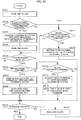
- FIG. 22 is a flowchart illustrating a first embodiment of taper machining processing executed by the numerical controller shown in FIG. 21 .
- the workpiece is assumed to be previously set and fixed obliquely.
- Step SA01 One block of the machining program is read.
- Step SA02 It is determined whether or not the read block is one that enables the coordinate system transformation function. If the block is determined to be such one, the program proceeds to Step SA03. If not, the program proceeds to Step SA11.
- Step SA03 A coordinate system for taper machining is arranged with a commanded coordinate system tilt angle.
- Step SA04 One block of the machining program is read.
- Step SA05 It is determined whether or not the taper machining is enabled. If the taper machining is enabled, the program proceeds to Step SA06. If not, the program proceeds to Step SA09. If M15 is described in the read block in Step SA05, it is determined that the taper machining is enabled. M15 is previously stored as modal information, which is handled thereafter as taper-machining-enabled information for a period before a block in which the taper machining is described as disabled.
- Step SA06 It is determined whether or not there is a command for the tilt of the wire electrode. If there is a tilt command, the program proceeds to Step SA07. If not, the program proceeds to Step SA13.
- Step SA07 The wire electrode tilt command is converted by means of the taper machining coordinate system arranged in Step SA03.
- Step SA08 The wire guide is moved so that the wire electrode is tilted according to the command converted in Step SA07.
- Step SA09 It is determined whether or not the program is finished. If the program is finished, this processing ends. If not, the program proceeds to Step SA10.
- Step SA10 One block of the machining program is read.
- Step SA11 It is determined whether or not the block read in Step SA10 is one that disables the coordinate system transformation function. If the block is determined to be such one, the program proceeds to Step SA12. If not, the program returns to Step SA05.
- Step SA12 The taper machining coordinate system is restored to the original coordinate system.
- Step SA13 It is determined whether or not the read block is a block for a move command. If the read block is a move command block, the program proceeds to Step SA14. If not, the program returns to Step SA09.
- Step SA14 The move command is converted by means of the taper machining coordinate system.
- Step SA15 The table or the wire guide is moved in response to the move command converted in Step SA14.
- FIG. 23 is a diagram illustrating the basic configuration and operation of another embodiment of the wire electric discharge machine according to the present invention.
- This wire electric discharge machine can machine the workpiece with the wire electrode kept substantial perpendicular to the table surface.
- the workpiece 3 is rotated and set in place such that its rotation angle is commanded according to the coordinate system tilt angle.
- the wire electrode is tilted so as to extend perpendicular to the rotated workpiece 3 at the machining start point (see OPERATION 1 in FIG. 23 ), so that the movable ranges of the upper and lower guides may possibly be exceeded. Therefore, the difference between the commanded taper angle and the current angle of the wire electrode on the transformed coordinate system is calculated by a machining command correction unit attached to the controller of the wire electric discharge machine, and the wire guide is controlled based on the calculated difference.
- the wire electrode 4 can be kept substantially perpendicular to the table surface as it is moved (see OPERATION 2 in FIG. 23 ), so that the upper and lower guides can be prevented from exceeding the movable ranges.
- FIG. 24 is a flowchart illustrating a second embodiment of the taper machining processing executed by the numerical controller shown in FIG. 21 . Various steps of operation will be described with reference to FIG. 23 . This flowchart is based on a machining program including a block that enables the coordinate system transformation function.
- Step SB01 The tilt of the workpiece is set by, for example, means shown in FIG. 20 .
- Step SB02 A direction perpendicular to the tilted workpiece is determined by calculation.
- Step SB03 The current tilt of the wire electrode is stored. According to the operation mode of the wire electric discharge machine shown in FIG. 23 , the current tilt of the wire electrode is equal to the commanded taper angle.
- Step SB04 One block is read.
- Step SB05 It is determined whether or not the wire electrode tilt command is included in the read block. If the tilt command is included, the program proceeds to Step SB06. If not, the program proceeds to Step SB07.
- Step SB06 The tilt of the wire electrode in the next processing period is calculated based on the direction perpendicular to the workpiece.
- Step SB07 The tilt of the wire electrode in the next processing period is set as the tilt of the wire electrode in the current processing period.
- Step SB08 It is determined whether or not the execution of the block read in Step SB04 is finished. If the execution is not finished, the program returns to Step SB04. If the execution is finished, the processing ends.
Landscapes
- Engineering & Computer Science (AREA)
- Automation & Control Theory (AREA)
- Chemical & Material Sciences (AREA)
- Chemical Kinetics & Catalysis (AREA)
- Electrochemistry (AREA)
- Mechanical Engineering (AREA)
- Human Computer Interaction (AREA)
- Manufacturing & Machinery (AREA)
- Physics & Mathematics (AREA)
- General Physics & Mathematics (AREA)
- Electrical Discharge Machining, Electrochemical Machining, And Combined Machining (AREA)
Applications Claiming Priority (1)
| Application Number | Priority Date | Filing Date | Title |
|---|---|---|---|
| JP2011129764A JP5108132B1 (ja) | 2011-06-10 | 2011-06-10 | 被加工物を傾けてテーパ加工を行うワイヤ放電加工機 |
Publications (3)
| Publication Number | Publication Date |
|---|---|
| EP2532464A2 true EP2532464A2 (fr) | 2012-12-12 |
| EP2532464A3 EP2532464A3 (fr) | 2013-10-23 |
| EP2532464B1 EP2532464B1 (fr) | 2016-02-24 |
Family
ID=45811294
Family Applications (1)
| Application Number | Title | Priority Date | Filing Date |
|---|---|---|---|
| EP12157434.7A Active EP2532464B1 (fr) | 2011-06-10 | 2012-02-29 | Procédé d'utilisation d'une machine d'étincelage à fil pour des usinages de surface inclinées en inclinant la pièce. |
Country Status (4)
| Country | Link |
|---|---|
| US (1) | US10046407B2 (fr) |
| EP (1) | EP2532464B1 (fr) |
| JP (1) | JP5108132B1 (fr) |
| CN (1) | CN102814563B (fr) |
Cited By (5)
| Publication number | Priority date | Publication date | Assignee | Title |
|---|---|---|---|---|
| EP2792444A3 (fr) * | 2013-04-15 | 2015-01-07 | Fanuc Corporation | Machine à décharge électrique à fil qui effectue des déblais de conicité |
| CN110064804A (zh) * | 2019-04-30 | 2019-07-30 | 中国航发南方工业有限公司 | 航空零部件空间角度小孔的加工方法 |
| CN110102842A (zh) * | 2019-06-11 | 2019-08-09 | 南京航空航天大学 | 一种基于小直径棒状电极的电火花切割桌面机床 |
| CN110961735A (zh) * | 2018-09-28 | 2020-04-07 | 富泰华工业(深圳)有限公司 | 线切割加工的平面校正方法和线切割机 |
| CN117139759A (zh) * | 2023-10-31 | 2023-12-01 | 赫比(成都)精密塑胶制品有限公司 | 多段异形锥形孔的加工方法及工件 |
Families Citing this family (12)
| Publication number | Priority date | Publication date | Assignee | Title |
|---|---|---|---|---|
| JP5088975B2 (ja) * | 2010-10-19 | 2012-12-05 | 株式会社ソディック | ワイヤ放電加工装置 |
| JP4938137B1 (ja) * | 2011-03-03 | 2012-05-23 | ファナック株式会社 | 被加工物の上面検出機能を有するワイヤカット放電加工機 |
| JP5199447B1 (ja) * | 2011-12-09 | 2013-05-15 | ファナック株式会社 | 回転軸を備えたワイヤ放電加工機 |
| JP5674848B2 (ja) | 2013-03-29 | 2015-02-25 | ファナック株式会社 | 自動結線機能を有するワイヤ放電加工機 |
| JP5752196B2 (ja) | 2013-09-03 | 2015-07-22 | ファナック株式会社 | ワイヤ放電加工機用のプログラム作成装置 |
| JP5788468B2 (ja) * | 2013-11-28 | 2015-09-30 | ファナック株式会社 | 駆動部品の摩耗を抑える機能を有するワイヤ放電加工機 |
| CN104607736B (zh) * | 2014-12-22 | 2017-02-22 | 中核(天津)科技发展有限公司 | 线切割加工薄壁管棱锥的方法及装具 |
| JP6480894B2 (ja) * | 2016-07-25 | 2019-03-13 | ファナック株式会社 | ワイヤ放電加工機及びワイヤ放電加工方法 |
| JP6404968B2 (ja) * | 2017-03-03 | 2018-10-17 | ファナック株式会社 | ワイヤ放電加工機 |
| CN107984046A (zh) * | 2017-12-28 | 2018-05-04 | 合肥硬核派科技有限公司 | 一种线切割用旋转加工设备及加工方法 |
| CN110091019B (zh) * | 2018-01-31 | 2021-01-19 | 衡阳市裕展精密科技有限公司 | 线切割加工机的角度校正方法与用于角度校正的校正块 |
| JP7498047B2 (ja) | 2020-07-14 | 2024-06-11 | 西部電機株式会社 | 精度補正方法及びワイヤ放電加工機 |
Citations (5)
| Publication number | Priority date | Publication date | Assignee | Title |
|---|---|---|---|---|
| JPH02139129A (ja) | 1988-11-21 | 1990-05-29 | Hitachi Seiko Ltd | ワイヤ放電加工機の平行度補正方法および装置 |
| JPH09267219A (ja) | 1996-04-02 | 1997-10-14 | Makino Milling Mach Co Ltd | 数値制御による総形工具の加工装置 |
| JP2000052153A (ja) | 1998-08-05 | 2000-02-22 | Ogura Jewel Ind Co Ltd | ワイヤカット放電加工機用ダイスガイド |
| JP2006055923A (ja) | 2004-08-18 | 2006-03-02 | Asahi Diamond Industrial Co Ltd | ワイヤ放電加工機用ワイヤガイド |
| JP2006159396A (ja) | 2004-11-15 | 2006-06-22 | Fanuc Ltd | ワイヤ放電加工機及びワイヤ放電加工方法 |
Family Cites Families (23)
| Publication number | Priority date | Publication date | Assignee | Title |
|---|---|---|---|---|
| CH513693A (de) * | 1970-07-03 | 1971-10-15 | Agie Ag Ind Elektronik | Elektroerosionsmaschine mit einer Steuerungsanordnung zum Steuern mindestens einer Vorschubeinrichtung für die Bewegung einer Drahtelektrode und/oder eines Werkstücks |
| JPS596157B2 (ja) * | 1976-07-23 | 1984-02-09 | 三菱電機株式会社 | 無整流子電動機の制御装置 |
| JPS58206316A (ja) * | 1982-05-28 | 1983-12-01 | Mitsubishi Electric Corp | 放電加工装置 |
| DE3419628C2 (de) * | 1984-05-16 | 1986-03-27 | Aktiengesellschaft für industrielle Elektronik AGIE Losone bei Locarno, Losone, Locarno | Vorrichtung für das Spülen der Erodierzone an funkenerosiven Schneidanlagen |
| JPS60259324A (ja) * | 1984-06-06 | 1985-12-21 | Mitsubishi Electric Corp | ワイヤ放電加工装置 |
| JPS61288929A (ja) * | 1985-06-15 | 1986-12-19 | Fanuc Ltd | ワイヤカツト放電加工機 |
| JPS62120919A (ja) * | 1985-11-20 | 1987-06-02 | Fanuc Ltd | ワイヤカツト放電加工方法 |
| DE3543482A1 (de) * | 1985-12-09 | 1987-06-11 | Siemens Ag | Verfahren und vorrichtung zum herstellen eines aus ferromagnetischem band gewickelten und stirnseitig genuteten ringfoermigen aktivteils fuer eine elektrische axialfeldmaschine |
| CH670590A5 (fr) * | 1987-04-03 | 1989-06-30 | Charmilles Technologies | |
| US4830261A (en) * | 1987-10-29 | 1989-05-16 | Laser Limited, Inc. | Eddy current tool positioning system |
| JPH0457624A (ja) * | 1990-06-25 | 1992-02-25 | Mitsubishi Electric Corp | ワイヤ放電加工装置 |
| DE4222186C2 (de) * | 1992-07-06 | 1996-06-20 | Agie Ag Ind Elektronik | Verfahren zum funkenerosiven Feinbearbeiten mittels drahtförmiger Elektroden und funkenerosive Schneidevorrichtung |
| JP2721092B2 (ja) * | 1992-08-05 | 1998-03-04 | 三菱電機株式会社 | ワイヤ放電加工装置 |
| JP3036337B2 (ja) * | 1993-11-19 | 2000-04-24 | ブラザー工業株式会社 | ワイヤ放電加工機 |
| CN2215370Y (zh) * | 1994-06-28 | 1995-12-20 | 国营庆安宇航设备公司 | 一种数控线切割机床的旋转坐标装置 |
| JP3596157B2 (ja) * | 1996-05-13 | 2004-12-02 | 松下電器産業株式会社 | 放電加工機 |
| JPH1058237A (ja) * | 1996-08-13 | 1998-03-03 | Toshiba Corp | ワイヤ放電加工機およびワイヤ放電加工方法 |
| CN1775442A (zh) | 2004-11-15 | 2006-05-24 | 发那科株式会社 | 电火花线切割机和电火花线切割加工方法 |
| JP4057624B2 (ja) | 2006-08-03 | 2008-03-05 | 株式会社三共 | 遊技機の基板収納ボックス |
| JP2010149213A (ja) * | 2008-12-24 | 2010-07-08 | Incs Inc | ワイヤ制御指令生成装置、及びワイヤ制御指令生成プログラム、並びにコンピュータ読取可能記憶媒体 |
| ES2427014T3 (es) * | 2009-01-29 | 2013-10-28 | Agie Charmilles Sa | Método y aparato de mecanizado por descarga eléctrica por hilo metálico |
| JP5271765B2 (ja) * | 2009-03-25 | 2013-08-21 | 株式会社ソディック | ワイヤカット放電加工装置におけるテーパ補正システムおよびテーパ補正方法 |
| JP6055354B2 (ja) | 2013-03-28 | 2016-12-27 | 東京応化工業株式会社 | 基板の処理方法 |
-
2011
- 2011-06-10 JP JP2011129764A patent/JP5108132B1/ja active Active
-
2012
- 2012-02-29 EP EP12157434.7A patent/EP2532464B1/fr active Active
- 2012-04-23 US US13/452,999 patent/US10046407B2/en active Active
- 2012-06-08 CN CN201210189490.5A patent/CN102814563B/zh active Active
Patent Citations (5)
| Publication number | Priority date | Publication date | Assignee | Title |
|---|---|---|---|---|
| JPH02139129A (ja) | 1988-11-21 | 1990-05-29 | Hitachi Seiko Ltd | ワイヤ放電加工機の平行度補正方法および装置 |
| JPH09267219A (ja) | 1996-04-02 | 1997-10-14 | Makino Milling Mach Co Ltd | 数値制御による総形工具の加工装置 |
| JP2000052153A (ja) | 1998-08-05 | 2000-02-22 | Ogura Jewel Ind Co Ltd | ワイヤカット放電加工機用ダイスガイド |
| JP2006055923A (ja) | 2004-08-18 | 2006-03-02 | Asahi Diamond Industrial Co Ltd | ワイヤ放電加工機用ワイヤガイド |
| JP2006159396A (ja) | 2004-11-15 | 2006-06-22 | Fanuc Ltd | ワイヤ放電加工機及びワイヤ放電加工方法 |
Cited By (8)
| Publication number | Priority date | Publication date | Assignee | Title |
|---|---|---|---|---|
| EP2792444A3 (fr) * | 2013-04-15 | 2015-01-07 | Fanuc Corporation | Machine à décharge électrique à fil qui effectue des déblais de conicité |
| US9381587B2 (en) | 2013-04-15 | 2016-07-05 | Fanuc Corporation | Wire electric discharge machine which performs taper cutting |
| CN110961735A (zh) * | 2018-09-28 | 2020-04-07 | 富泰华工业(深圳)有限公司 | 线切割加工的平面校正方法和线切割机 |
| CN110961735B (zh) * | 2018-09-28 | 2024-05-10 | 富泰华工业(深圳)有限公司 | 线切割加工的平面校正方法和线切割机 |
| CN110064804A (zh) * | 2019-04-30 | 2019-07-30 | 中国航发南方工业有限公司 | 航空零部件空间角度小孔的加工方法 |
| CN110102842A (zh) * | 2019-06-11 | 2019-08-09 | 南京航空航天大学 | 一种基于小直径棒状电极的电火花切割桌面机床 |
| CN117139759A (zh) * | 2023-10-31 | 2023-12-01 | 赫比(成都)精密塑胶制品有限公司 | 多段异形锥形孔的加工方法及工件 |
| CN117139759B (zh) * | 2023-10-31 | 2024-01-23 | 赫比(成都)精密塑胶制品有限公司 | 多段异形锥形孔的加工方法及工件 |
Also Published As
| Publication number | Publication date |
|---|---|
| CN102814563B (zh) | 2014-11-05 |
| EP2532464B1 (fr) | 2016-02-24 |
| JP5108132B1 (ja) | 2012-12-26 |
| EP2532464A3 (fr) | 2013-10-23 |
| US20120312786A1 (en) | 2012-12-13 |
| JP2012254505A (ja) | 2012-12-27 |
| CN102814563A (zh) | 2012-12-12 |
| US10046407B2 (en) | 2018-08-14 |
Similar Documents
| Publication | Publication Date | Title |
|---|---|---|
| EP2532464B1 (fr) | Procédé d'utilisation d'une machine d'étincelage à fil pour des usinages de surface inclinées en inclinant la pièce. | |
| EP2626161B1 (fr) | Procédé d'usinage d'outil de tournage avec une machine à décharge électrique à fil, système comprenant un outil de tournage et une machine à décharge électrique à fil pour effectuer l'usinage d'un outil de tournage, et procédé de création de programme pour machine à décharge électrique à fil qui effectue l'usinage d'un outil de tournage | |
| EP2495063B1 (fr) | Machine de décharge électrique à coupe-pâte dotée d'une fonction de détection de surface supérieure de pièce de travail | |
| EP2295180A2 (fr) | Procédé d'usinage à décharge électrique, appareil correspondant, dispositif de création de programme d'usinage à décharge électrique, et support d'enregistrement lisible sur ordinateur dans lequel un programme de création du programme d'usinage à décharge électrique est stocké | |
| EP2617506B1 (fr) | Machine à décharge électrique à fil pour l'usinage par décharge électrique par l'inclinaison d'électrode à fil | |
| CN103286397B (zh) | 减少加工损伤的电火花线切割机以及电火花线切割方法 | |
| EP2792444B1 (fr) | Machine à décharge électrique à fil qui effectue des déblais de conicité | |
| KR101980416B1 (ko) | 임의의 퇴피 위치로부터 방전 상태에서 이동시켜 중단 위치로 복귀하는 기능을 갖는 와이어 방전 가공기 | |
| EP3023186A1 (fr) | Machine de décharge électrique á fil avec une fonction de correction de coin | |
| JP5731613B2 (ja) | ワイヤ放電加工機およびワイヤ放電加工機の制御装置 | |
| EP3708286A1 (fr) | Machine à décharge électrique à fil et éditeur de programme d'usinage | |
| CN106493469B (zh) | 能够根据姿势来控制加工条件的数值控制装置 | |
| EP2845677B1 (fr) | Appareil de commande numérique pour commander une machine à décharge électrique à fil qui effectue un usinage conique | |
| JP4995976B1 (ja) | 回転軸のインポジションチェックを行う数値制御装置 | |
| US20090194511A1 (en) | Wire electrical discharge machining | |
| EP2730986B1 (fr) | Contrôleur de machine de décharge électrique à fil, machine à décharge électrique à fil et procédé d'usinage par décharge électrique à fil | |
| JP5877915B2 (ja) | 工作機械を制御する数値制御装置 | |
| JP2019130641A (ja) | ワイヤ放電加工機、および、ワイヤ放電加工機の制御方法 | |
| JP2021002092A (ja) | 数値制御装置 | |
| KR100579089B1 (ko) | 5축 와이어 방전가공기 | |
| JPS6331331B2 (fr) |
Legal Events
| Date | Code | Title | Description |
|---|---|---|---|
| PUAI | Public reference made under article 153(3) epc to a published international application that has entered the european phase |
Free format text: ORIGINAL CODE: 0009012 |
|
| AK | Designated contracting states |
Kind code of ref document: A2 Designated state(s): AL AT BE BG CH CY CZ DE DK EE ES FI FR GB GR HR HU IE IS IT LI LT LU LV MC MK MT NL NO PL PT RO RS SE SI SK SM TR |
|
| AX | Request for extension of the european patent |
Extension state: BA ME |
|
| PUAL | Search report despatched |
Free format text: ORIGINAL CODE: 0009013 |
|
| AK | Designated contracting states |
Kind code of ref document: A3 Designated state(s): AL AT BE BG CH CY CZ DE DK EE ES FI FR GB GR HR HU IE IS IT LI LT LU LV MC MK MT NL NO PL PT RO RS SE SI SK SM TR |
|
| AX | Request for extension of the european patent |
Extension state: BA ME |
|
| RIC1 | Information provided on ipc code assigned before grant |
Ipc: B23H 7/20 20060101ALI20130916BHEP Ipc: B23H 1/00 20060101AFI20130916BHEP Ipc: B23H 7/06 20060101ALI20130916BHEP Ipc: G05B 19/408 20060101ALI20130916BHEP |
|
| 17P | Request for examination filed |
Effective date: 20140317 |
|
| RBV | Designated contracting states (corrected) |
Designated state(s): AL AT BE BG CH CY CZ DE DK EE ES FI FR GB GR HR HU IE IS IT LI LT LU LV MC MK MT NL NO PL PT RO RS SE SI SK SM TR |
|
| 17Q | First examination report despatched |
Effective date: 20141205 |
|
| GRAP | Despatch of communication of intention to grant a patent |
Free format text: ORIGINAL CODE: EPIDOSNIGR1 |
|
| INTG | Intention to grant announced |
Effective date: 20150916 |
|
| GRAS | Grant fee paid |
Free format text: ORIGINAL CODE: EPIDOSNIGR3 |
|
| GRAA | (expected) grant |
Free format text: ORIGINAL CODE: 0009210 |
|
| AK | Designated contracting states |
Kind code of ref document: B1 Designated state(s): AL AT BE BG CH CY CZ DE DK EE ES FI FR GB GR HR HU IE IS IT LI LT LU LV MC MK MT NL NO PL PT RO RS SE SI SK SM TR |
|
| REG | Reference to a national code |
Ref country code: GB Ref legal event code: FG4D |
|
| REG | Reference to a national code |
Ref country code: CH Ref legal event code: EP Ref country code: CH Ref legal event code: NV Representative=s name: DR. LUSUARDI AG, CH |
|
| REG | Reference to a national code |
Ref country code: AT Ref legal event code: REF Ref document number: 776416 Country of ref document: AT Kind code of ref document: T Effective date: 20160315 |
|
| REG | Reference to a national code |
Ref country code: IE Ref legal event code: FG4D |
|
| REG | Reference to a national code |
Ref country code: DE Ref legal event code: R096 Ref document number: 602012014824 Country of ref document: DE |
|
| REG | Reference to a national code |
Ref country code: LT Ref legal event code: MG4D |
|
| REG | Reference to a national code |
Ref country code: NL Ref legal event code: MP Effective date: 20160224 |
|
| REG | Reference to a national code |
Ref country code: AT Ref legal event code: MK05 Ref document number: 776416 Country of ref document: AT Kind code of ref document: T Effective date: 20160224 |
|
| PG25 | Lapsed in a contracting state [announced via postgrant information from national office to epo] |
Ref country code: ES Free format text: LAPSE BECAUSE OF FAILURE TO SUBMIT A TRANSLATION OF THE DESCRIPTION OR TO PAY THE FEE WITHIN THE PRESCRIBED TIME-LIMIT Effective date: 20160224 Ref country code: NO Free format text: LAPSE BECAUSE OF FAILURE TO SUBMIT A TRANSLATION OF THE DESCRIPTION OR TO PAY THE FEE WITHIN THE PRESCRIBED TIME-LIMIT Effective date: 20160524 Ref country code: FI Free format text: LAPSE BECAUSE OF FAILURE TO SUBMIT A TRANSLATION OF THE DESCRIPTION OR TO PAY THE FEE WITHIN THE PRESCRIBED TIME-LIMIT Effective date: 20160224 Ref country code: IT Free format text: LAPSE BECAUSE OF FAILURE TO SUBMIT A TRANSLATION OF THE DESCRIPTION OR TO PAY THE FEE WITHIN THE PRESCRIBED TIME-LIMIT Effective date: 20160224 Ref country code: HR Free format text: LAPSE BECAUSE OF FAILURE TO SUBMIT A TRANSLATION OF THE DESCRIPTION OR TO PAY THE FEE WITHIN THE PRESCRIBED TIME-LIMIT Effective date: 20160224 Ref country code: GR Free format text: LAPSE BECAUSE OF FAILURE TO SUBMIT A TRANSLATION OF THE DESCRIPTION OR TO PAY THE FEE WITHIN THE PRESCRIBED TIME-LIMIT Effective date: 20160525 |
|
| PG25 | Lapsed in a contracting state [announced via postgrant information from national office to epo] |
Ref country code: PT Free format text: LAPSE BECAUSE OF FAILURE TO SUBMIT A TRANSLATION OF THE DESCRIPTION OR TO PAY THE FEE WITHIN THE PRESCRIBED TIME-LIMIT Effective date: 20160624 Ref country code: NL Free format text: LAPSE BECAUSE OF FAILURE TO SUBMIT A TRANSLATION OF THE DESCRIPTION OR TO PAY THE FEE WITHIN THE PRESCRIBED TIME-LIMIT Effective date: 20160224 Ref country code: LT Free format text: LAPSE BECAUSE OF FAILURE TO SUBMIT A TRANSLATION OF THE DESCRIPTION OR TO PAY THE FEE WITHIN THE PRESCRIBED TIME-LIMIT Effective date: 20160224 Ref country code: RS Free format text: LAPSE BECAUSE OF FAILURE TO SUBMIT A TRANSLATION OF THE DESCRIPTION OR TO PAY THE FEE WITHIN THE PRESCRIBED TIME-LIMIT Effective date: 20160224 Ref country code: AT Free format text: LAPSE BECAUSE OF FAILURE TO SUBMIT A TRANSLATION OF THE DESCRIPTION OR TO PAY THE FEE WITHIN THE PRESCRIBED TIME-LIMIT Effective date: 20160224 Ref country code: BE Free format text: LAPSE BECAUSE OF NON-PAYMENT OF DUE FEES Effective date: 20160229 Ref country code: SE Free format text: LAPSE BECAUSE OF FAILURE TO SUBMIT A TRANSLATION OF THE DESCRIPTION OR TO PAY THE FEE WITHIN THE PRESCRIBED TIME-LIMIT Effective date: 20160224 Ref country code: LV Free format text: LAPSE BECAUSE OF FAILURE TO SUBMIT A TRANSLATION OF THE DESCRIPTION OR TO PAY THE FEE WITHIN THE PRESCRIBED TIME-LIMIT Effective date: 20160224 Ref country code: PL Free format text: LAPSE BECAUSE OF FAILURE TO SUBMIT A TRANSLATION OF THE DESCRIPTION OR TO PAY THE FEE WITHIN THE PRESCRIBED TIME-LIMIT Effective date: 20160224 |
|
| PG25 | Lapsed in a contracting state [announced via postgrant information from national office to epo] |
Ref country code: EE Free format text: LAPSE BECAUSE OF FAILURE TO SUBMIT A TRANSLATION OF THE DESCRIPTION OR TO PAY THE FEE WITHIN THE PRESCRIBED TIME-LIMIT Effective date: 20160224 Ref country code: DK Free format text: LAPSE BECAUSE OF FAILURE TO SUBMIT A TRANSLATION OF THE DESCRIPTION OR TO PAY THE FEE WITHIN THE PRESCRIBED TIME-LIMIT Effective date: 20160224 |
|
| REG | Reference to a national code |
Ref country code: DE Ref legal event code: R097 Ref document number: 602012014824 Country of ref document: DE |
|
| PG25 | Lapsed in a contracting state [announced via postgrant information from national office to epo] |
Ref country code: RO Free format text: LAPSE BECAUSE OF FAILURE TO SUBMIT A TRANSLATION OF THE DESCRIPTION OR TO PAY THE FEE WITHIN THE PRESCRIBED TIME-LIMIT Effective date: 20160224 Ref country code: SK Free format text: LAPSE BECAUSE OF FAILURE TO SUBMIT A TRANSLATION OF THE DESCRIPTION OR TO PAY THE FEE WITHIN THE PRESCRIBED TIME-LIMIT Effective date: 20160224 Ref country code: SM Free format text: LAPSE BECAUSE OF FAILURE TO SUBMIT A TRANSLATION OF THE DESCRIPTION OR TO PAY THE FEE WITHIN THE PRESCRIBED TIME-LIMIT Effective date: 20160224 Ref country code: CZ Free format text: LAPSE BECAUSE OF FAILURE TO SUBMIT A TRANSLATION OF THE DESCRIPTION OR TO PAY THE FEE WITHIN THE PRESCRIBED TIME-LIMIT Effective date: 20160224 |
|
| REG | Reference to a national code |
Ref country code: IE Ref legal event code: MM4A |
|
| PG25 | Lapsed in a contracting state [announced via postgrant information from national office to epo] |
Ref country code: BE Free format text: LAPSE BECAUSE OF FAILURE TO SUBMIT A TRANSLATION OF THE DESCRIPTION OR TO PAY THE FEE WITHIN THE PRESCRIBED TIME-LIMIT Effective date: 20160224 |
|
| PLBE | No opposition filed within time limit |
Free format text: ORIGINAL CODE: 0009261 |
|
| STAA | Information on the status of an ep patent application or granted ep patent |
Free format text: STATUS: NO OPPOSITION FILED WITHIN TIME LIMIT |
|
| GBPC | Gb: european patent ceased through non-payment of renewal fee |
Effective date: 20160524 |
|
| PG25 | Lapsed in a contracting state [announced via postgrant information from national office to epo] |
Ref country code: IE Free format text: LAPSE BECAUSE OF NON-PAYMENT OF DUE FEES Effective date: 20160229 |
|
| 26N | No opposition filed |
Effective date: 20161125 |
|
| REG | Reference to a national code |
Ref country code: FR Ref legal event code: ST Effective date: 20170104 |
|
| PG25 | Lapsed in a contracting state [announced via postgrant information from national office to epo] |
Ref country code: SI Free format text: LAPSE BECAUSE OF FAILURE TO SUBMIT A TRANSLATION OF THE DESCRIPTION OR TO PAY THE FEE WITHIN THE PRESCRIBED TIME-LIMIT Effective date: 20160224 Ref country code: BG Free format text: LAPSE BECAUSE OF FAILURE TO SUBMIT A TRANSLATION OF THE DESCRIPTION OR TO PAY THE FEE WITHIN THE PRESCRIBED TIME-LIMIT Effective date: 20160524 |
|
| PG25 | Lapsed in a contracting state [announced via postgrant information from national office to epo] |
Ref country code: FR Free format text: LAPSE BECAUSE OF NON-PAYMENT OF DUE FEES Effective date: 20160425 |
|
| PG25 | Lapsed in a contracting state [announced via postgrant information from national office to epo] |
Ref country code: GB Free format text: LAPSE BECAUSE OF NON-PAYMENT OF DUE FEES Effective date: 20160524 |
|
| PG25 | Lapsed in a contracting state [announced via postgrant information from national office to epo] |
Ref country code: MT Free format text: LAPSE BECAUSE OF FAILURE TO SUBMIT A TRANSLATION OF THE DESCRIPTION OR TO PAY THE FEE WITHIN THE PRESCRIBED TIME-LIMIT Effective date: 20160224 |
|
| PG25 | Lapsed in a contracting state [announced via postgrant information from national office to epo] |
Ref country code: CY Free format text: LAPSE BECAUSE OF FAILURE TO SUBMIT A TRANSLATION OF THE DESCRIPTION OR TO PAY THE FEE WITHIN THE PRESCRIBED TIME-LIMIT Effective date: 20160224 Ref country code: HU Free format text: LAPSE BECAUSE OF FAILURE TO SUBMIT A TRANSLATION OF THE DESCRIPTION OR TO PAY THE FEE WITHIN THE PRESCRIBED TIME-LIMIT; INVALID AB INITIO Effective date: 20120229 |
|
| PG25 | Lapsed in a contracting state [announced via postgrant information from national office to epo] |
Ref country code: MT Free format text: LAPSE BECAUSE OF FAILURE TO SUBMIT A TRANSLATION OF THE DESCRIPTION OR TO PAY THE FEE WITHIN THE PRESCRIBED TIME-LIMIT Effective date: 20160229 Ref country code: LU Free format text: LAPSE BECAUSE OF NON-PAYMENT OF DUE FEES Effective date: 20160229 Ref country code: MK Free format text: LAPSE BECAUSE OF FAILURE TO SUBMIT A TRANSLATION OF THE DESCRIPTION OR TO PAY THE FEE WITHIN THE PRESCRIBED TIME-LIMIT Effective date: 20160224 Ref country code: IS Free format text: LAPSE BECAUSE OF FAILURE TO SUBMIT A TRANSLATION OF THE DESCRIPTION OR TO PAY THE FEE WITHIN THE PRESCRIBED TIME-LIMIT Effective date: 20160224 Ref country code: MC Free format text: LAPSE BECAUSE OF FAILURE TO SUBMIT A TRANSLATION OF THE DESCRIPTION OR TO PAY THE FEE WITHIN THE PRESCRIBED TIME-LIMIT Effective date: 20160224 Ref country code: TR Free format text: LAPSE BECAUSE OF FAILURE TO SUBMIT A TRANSLATION OF THE DESCRIPTION OR TO PAY THE FEE WITHIN THE PRESCRIBED TIME-LIMIT Effective date: 20160224 |
|
| PG25 | Lapsed in a contracting state [announced via postgrant information from national office to epo] |
Ref country code: AL Free format text: LAPSE BECAUSE OF FAILURE TO SUBMIT A TRANSLATION OF THE DESCRIPTION OR TO PAY THE FEE WITHIN THE PRESCRIBED TIME-LIMIT Effective date: 20160224 |
|
| REG | Reference to a national code |
Ref country code: DE Ref legal event code: R082 Ref document number: 602012014824 Country of ref document: DE Representative=s name: HL KEMPNER PATENTANWAELTE, SOLICITORS (ENGLAND, DE Ref country code: DE Ref legal event code: R082 Ref document number: 602012014824 Country of ref document: DE Representative=s name: HL KEMPNER PATENTANWALT, RECHTSANWALT, SOLICIT, DE Ref country code: DE Ref legal event code: R082 Ref document number: 602012014824 Country of ref document: DE Representative=s name: HL KEMPNER PARTG MBB, DE |
|
| REG | Reference to a national code |
Ref country code: CH Ref legal event code: U11 Free format text: ST27 STATUS EVENT CODE: U-0-0-U10-U11 (AS PROVIDED BY THE NATIONAL OFFICE) Effective date: 20260301 |
|
| PGFP | Annual fee paid to national office [announced via postgrant information from national office to epo] |
Ref country code: DE Payment date: 20260121 Year of fee payment: 15 |
|
| PGFP | Annual fee paid to national office [announced via postgrant information from national office to epo] |
Ref country code: CH Payment date: 20260301 Year of fee payment: 15 |