EP2545815B1 - Klebefolienartige Haltevorrichtung zur Wandmontage - Google Patents
Klebefolienartige Haltevorrichtung zur Wandmontage Download PDFInfo
- Publication number
- EP2545815B1 EP2545815B1 EP12186808.7A EP12186808A EP2545815B1 EP 2545815 B1 EP2545815 B1 EP 2545815B1 EP 12186808 A EP12186808 A EP 12186808A EP 2545815 B1 EP2545815 B1 EP 2545815B1
- Authority
- EP
- European Patent Office
- Prior art keywords
- wall
- adhesive sheet
- base
- holding device
- adhesive
- Prior art date
- Legal status (The legal status is an assumption and is not a legal conclusion. Google has not performed a legal analysis and makes no representation as to the accuracy of the status listed.)
- Expired - Lifetime
Links
- 239000000853 adhesive Substances 0.000 title claims abstract description 99
- 230000001070 adhesive effect Effects 0.000 title claims abstract description 99
- 238000005096 rolling process Methods 0.000 claims description 24
- 230000004888 barrier function Effects 0.000 claims description 4
- 239000013013 elastic material Substances 0.000 claims description 3
- 230000000694 effects Effects 0.000 abstract description 9
- 239000000126 substance Substances 0.000 description 4
- 241000817702 Acetabula Species 0.000 description 3
- 239000011888 foil Substances 0.000 description 3
- 239000007787 solid Substances 0.000 description 3
- 239000004831 Hot glue Substances 0.000 description 2
- 229910052782 aluminium Inorganic materials 0.000 description 2
- XAGFODPZIPBFFR-UHFFFAOYSA-N aluminium Chemical compound [Al] XAGFODPZIPBFFR-UHFFFAOYSA-N 0.000 description 2
- 239000003292 glue Substances 0.000 description 2
- 239000000463 material Substances 0.000 description 2
- 239000007779 soft material Substances 0.000 description 2
- 230000003068 static effect Effects 0.000 description 2
- 229920001328 Polyvinylidene chloride Polymers 0.000 description 1
- 229910000639 Spring steel Inorganic materials 0.000 description 1
- 239000000919 ceramic Substances 0.000 description 1
- 239000007799 cork Substances 0.000 description 1
- 239000011521 glass Substances 0.000 description 1
- 210000003041 ligament Anatomy 0.000 description 1
- 229910052751 metal Inorganic materials 0.000 description 1
- 239000002184 metal Substances 0.000 description 1
- 239000004033 plastic Substances 0.000 description 1
- 239000005033 polyvinylidene chloride Substances 0.000 description 1
- 238000007665 sagging Methods 0.000 description 1
- 239000000344 soap Substances 0.000 description 1
- 238000001179 sorption measurement Methods 0.000 description 1
Images




Classifications
-
- F—MECHANICAL ENGINEERING; LIGHTING; HEATING; WEAPONS; BLASTING
- F16—ENGINEERING ELEMENTS AND UNITS; GENERAL MEASURES FOR PRODUCING AND MAINTAINING EFFECTIVE FUNCTIONING OF MACHINES OR INSTALLATIONS; THERMAL INSULATION IN GENERAL
- F16B—DEVICES FOR FASTENING OR SECURING CONSTRUCTIONAL ELEMENTS OR MACHINE PARTS TOGETHER, e.g. NAILS, BOLTS, CIRCLIPS, CLAMPS, CLIPS OR WEDGES; JOINTS OR JOINTING
- F16B47/00—Suction cups for attaching purposes; Equivalent means using adhesives
-
- A—HUMAN NECESSITIES
- A47—FURNITURE; DOMESTIC ARTICLES OR APPLIANCES; COFFEE MILLS; SPICE MILLS; SUCTION CLEANERS IN GENERAL
- A47G—HOUSEHOLD OR TABLE EQUIPMENT
- A47G1/00—Mirrors; Picture frames or the like, e.g. provided with heating, lighting or ventilating means
- A47G1/16—Devices for hanging or supporting pictures, mirrors, or the like
- A47G1/17—Devices for hanging or supporting pictures, mirrors, or the like using adhesives, suction or magnetism
Definitions
- the present invention relates to a holding device, more particularly, to a holding device for mounting onto a wall.
- a holding device for mounting onto a wall is a device mounted onto wall surface for holding or hanging something, such as a coat and hat hook, a soap holder, a bathroom towel rack and the like.
- the known holding device for mounting onto a wall generally comprises a base and a holder with an appropriate shape of a bracket connected with the base for holding or hanging commodities.
- the base of the holder of the holding device for a wall has to be securely and durably fixed on a wall in order to hold commodities securely but not to damage and affect the surface of the wall.
- the base is fixed onto a wall by hammering nails into the wall, adsorbing thereon with suction by an acetabula, or cementing thereon with a sheet having glue at its double faces, hot-melt adhesive and the like.
- the wall surface sometimes would be prone to be damaged if the base is fixed by hammering nails into the wall, the adsorbing force and duration is not ideal due to the limitation of the area and the air tightness of the acetabula if the base is fixed by adsorbing thereon with the acetabula, while the fastness is not enough due to the limitation of the adhesive force if the base is fixed by cementing thereon with a sheet having glue at its double faces or hot-melt adhesive.
- US 4,309,011 A discloses an adhesive sheet type holding device for mounting onto a wall, including a base and holder which is made in the shape of an appropriate support and attached to the base, whereby the device also includes an adhesive sheet which has a well air tightness and can be tightly attached on a wall, the adhesive sheet is attached to the base with the surface of the adhesive sheet extended outwards beyond the edge of the base.
- the holding device very tightly on the wall.
- the present invention provides an adhesive sheet type holding device as defined in claim 1.
- the adhesive sheet may be paper and film provided on the back side thereof with adhesive or flexible solid (ropy or gelatiniform) filling substance or the adhesive sheet may be an electrostatic paster with no adhesive on the back side thereof and with a highly smooth surface.
- the electrostatic paster can be used for smooth wall surfaces such as glass, ceramic tile, plastic and baking finish surface, the adhesive sheet with adhesive on its back can be used for the general wall surface, while the adhesive sheet with flexible solid filling substance on its back can be suitable for the rough surface since the filling substance can fill in the depression on the surface so that the adhesive sheet with flexible solid filling substance on its back can be tightly mounted on the wall.
- the adhesive sheet is attached onto a wall, and it comes into tight contact with the wall to achieve excellent air-tight effect due to the adhesive on its back or the adsorption affinity of its surface.
- the force applied to the base causes the adhesive sheet to be detached from the wall and generates a negative pressure clearance between them.
- the base and the adhesive sheet is pressed against the wall due to the air pressure so that the holding device can be fixed on the wall securely and durably.
- the adhesive sheet type holding device according to present invention can be fixed on the wall securely and durably since it is mounted onto a wall through the adhesive sheet which has contact area with the wall larger than the area of the back of the base and good airtight effect between the sheet and the wall,
- the adhesive sheet may be transparent or be printed with various specific pattern on its surface, so the holding device according to the present invention not only cannot damage to the wall, but also can form various specific appearance.
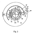
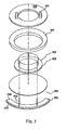
- an adhesive sheet type holding device for mounting onto a wall includes an adhesive paper sheet 401, a base 402, a friction plate 404, a rolling ring 441, a pressing roller 442, a pressing plate 405, a peeling piece 413 and a holder 403 (only shown in the fig. 2 ).
- the external surface 411 of the adhesive paper sheet 401 having a round shape is stuck on the surface of the base 402 pressing against the wall and the surface of the friction plate 404 pressing against the wall.
- the adhesive paper sheet 401 is provided with adhesive on the internal surface thereof to be stuck on the wall.
- the base 402 having a round shape is provided with ligaments on the periphery thereof and is connected with the friction plates 404 having the shape of a circular ring. Slants engaging with each other are provided on the periphery of the base 402 and the internal periphery of the friction plate 404.
- the slant of the base 402 rides on the slant of the friction plate 404 and thus the base 402 is pushed up and detached from the wall, so that the adhesive paper sheet 401 attached to the base 402 follows the latter to depart from the portion of wall.
- the base 402 is provided at the center thereof with a groove 424 formed with a hinge 4241 on the lower end thereof. As shown in the fig. 3 , the upper end of the groove 424 closes if no force is applied thereto, and the back side of the base 402, i.e. a press attaching surface 4211, is formed with the shape of a protrusion projected towards the wall (downwards). As a result, when the base 402 is pressed and attached onto the wall, the center portion of the base 402 firstly contacts with the wall, so that the air between the adhesive paper sheet 401 and the wall is ejected outwards from the center portion.
- the press attaching surface 4211 may be formed into a spherical surface projecting downwards, provided thereon with elastic material and a hollow chamber to be planished outwards from the center portion as the above.
- the rolling ring 441 which has a ring shape with its inner ring projecting towards the adhesive paper sheet 401 and which may be made of elastic material such as spring steel sheet.
- the center of the rolling ring 441 When the rolling ring 441 is pressed onto the wall, the center of the rolling ring 441 firstly presses the adhesive paper sheet 401 against the wall, and continuously pushing the rolling ring 441 causes the inner ring of the rolling ring 441 to be bent upwards and the entire rolling ring 441 gradually turns upwards, so that the adhesive paper sheet 401 is continuously rolled toward the outer periphery thereof from the inner portion by the rolling ring 441 and the air is ejected so as to be pressed tightly on the wall.
- the pressing plate 405 is disposed above the rolling ring 441 and is provided with two long springs having the shape of a arched plate which are capable of pushing the base 402 and two short springs which are capable of pushing the friction plate 404.
- a pressing foot 453 in a circular ring shape for pushing the outer edge of the rolling ring 441 is also provided around the pressing plate 405.
- a soft cushion 4311 can be provided on the surfaces of the base 402, the friction plate 404 and the rolling ring which are pressed onto the wall, so that the adhesive paper sheet 401 can be yieldingly pressed onto the wall.
- the pressing roller 442 is also disposed on the base 402.
- the pressing roller 442 has the shape of a roller and is provided at the axis thereof with a shaft hole 4422 through which a shaft 406 is disposed.
- One end 461 of the shaft 406 is big enough to prevent the pressing roller 442 from detaching from the shaft 406 and the other end is bent and connected to the circular ring 463.
- the circular ring 463 is fitted over a groove 4251 provided on the cylindrical portion 425 of the base 402 projecting upwards, so that the pressing roller 442 can rotate around the base 402.
- the rolling body of the pressing roller 442 is formed into an appropriate taper.
- the pressing roller 442 can be pushed to rotate and pressed by griping a gripe 464 provided on the shaft 406. It can be seen from the fig. 10 2 that the axis of the pressing roller 442 is inclined by an angle with respect to the radius of the base 402.
- the gripe 464 is griped and rotated clockwise, the more close the portion is to the center of the adhesive paper sheet 401, the more earlier the portion is pressed, while the farther the portion is from the center of the adhesive paper sheet 401, the later the portion is pressed.
- the pressing roller 442 is provided with soft material on the rolling surface so that the adhesive paper sheet 401 can be yieldingly pressed onto the wall.
- a peeling piece 413 extending upwards is also provided on edge of the outer surface of the adhesive paper sheet.
- the edge of the adhesive paper sheet can be pulled and detached from the wall and thus the whole holding device can be removed from the wall by pulling the peeling piece 413 up.
- an adhesive sheet type holding device for mounting onto a wall includes an adhesive paper sheet 501, a base 502, a friction plate 506, a rolling ring 541, a pressing plate 505 and a holder 503 (only shown in the fig. 6 ).
- the structure in the second embodiment is similar to that in the first embodiment except that the friction plate 506 is connected with the base 502 via detachable connecting rods 534 and is directly pressed against the wall 507 on the outside of the area of the adhesive paper sheet 501.since some adhesive paper sheet tend to slide on the wall after they have been pressed for a long time, a material with high coefficient of friction such as foamed rubber and cork is provided on the surface of the friction plate 506.
- the connecting rods 534 connected with the friction plate are inserted into the corresponding holes in the base and connected with the base, and the adhesive sheet type holding device for mounting onto a wall may be stuck onto the wall before or after the friction plate is assembled on the base during the assembly.
- the holder 503 may be connected to the base 502 or the connecting rods 534 of the friction plate 506.
- the rolling ring 541 made of thick and soft materials has a ring shape with its inner ring projecting towards the adhesive paper sheet, like the above structure. Since the rolling ring 541 is thick, the pressing foot does not have to be projected downwards as that in the fig.3 and the short springs are no longer used.
- the base 502 is pressed onto the wall 507 by the pressing plate 505, the long spring 551 firstly presses the base 502 flatly against the wall, then, the rolling ring 541 is pushed by the pressing plate 505 to be deformed and to gradually contact and press the adhesive paper sheet 501 from the center to the outer periphery thereof.
- the air between the adhesive paper sheet 501 and the wall 507 is continuously squeezed out from the center to the outer periphery.
- the friction plate 506 connected with the base 502 by the connecting rods 534 can be directly pressed against the wall 507.
- the base and the adhesive paper sheet can be made of materials with high gas barrier property, on the other hand, an air barrier layer may be provided on the surface of the center portion of the adhesive paper sheet and it may be metal foil or PVDC of the like.
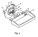
- an adhesive sheet type holding device for mounting onto a wall includes an adhesive paper sheet 601, a base 602, a rolling ring 641, a pressing roller 642, a pressing plate 605, a peeling piece 613 and a holder 603.
- the structure in the third embodiment is similar to that in the first embodiment except that a piece of aluminum foil 611 is stuck between the base 602 and the adhesive paper sheet 601 and has an area slightly larger than that of the base 602. Thus, better air-tight effect can be achieved by way of the excellent gas barrier property of the aluminum foil layer.
- the holder 603 has the shape of a basket ring and is provided on the base 602.
- the friction plate 606 is fixed on the side of the basket ring shaped holder 603 which is towards the wall.
- the friction plate 606 is provided under the adhesive paper sheet 601 and is directly pressed against the surface of the wall.
- the friction plate 606 is also provided with a friction sheet 616 with high frictional coefficient on the surface thereof which is towards the wall.
- a torque applied on the base will be generated.
- the torque pulls and detaches the base from the wall while it presses the friction plate onto the wall.
- the sizes of the device can be so designed that the maximal static frictional force between the friction plate and the wall will be enough to bear the weight of the object and the holder within the maximal static frictional force.
- the friction plate bears all of the weight, while the base only bears the force perpendicular to the wall. Therefore, the adhesive sheet type holding device for mounting onto a wall according to the present invention can bear large load and can be fixed on the wall securely and durably.
Landscapes
- Engineering & Computer Science (AREA)
- General Engineering & Computer Science (AREA)
- Mechanical Engineering (AREA)
- Hooks, Suction Cups, And Attachment By Adhesive Means (AREA)
- Supports Or Holders For Household Use (AREA)
- Adhesives Or Adhesive Processes (AREA)
- Finishing Walls (AREA)
Claims (7)
- Halteeinrichtung vom Typ eines Klebebands, zur Anordnung an einer Wand, aufweisend eine Basis (402; 502; 602) und eine Halteeinrichtung (403; 503; 603), die in einer für eine Halterung geeigneten Form hergestellt ist und an der Basis (402; 502; 602) haftet, wobei die Halteeinrichtung ferner ein Klebeband (401; 501; 601) aufweist, das eine gute Luftdichtigkeit aufweist und eng an der Wand kleben kann, wobei das Klebeband (401; 501; 601) an der Basis (402; 502; 602) angeordnet ist und wobei sich die Oberfläche des Klebebands (401; 501; 601) unterhalb des Randes der Basis (402; 502; 602) nach außen erstreckt, dadurch gekennzeichnet,
dass ein Rollenring (441; 541; 641) aus elastischem Material um den äußeren Rand der Basis (402; 502; 602) angeordnet ist und einen Innenring aufweist, der in Richtung des Klebebands (401; 501; 601) vorsteht, wobei eine Druckplatte (405; 505; 605), um die Basis (402; 502; 602) und den Rollenring (441; 541; 641) zu drücken, oberhalb des Rollenrings (441; 541; 641) angeordnet ist, - Halteeinrichtung vom Typ eines Klebebands nach Anspruch 1, dadurch gekennzeichnet, dass eine Luftgrenzschicht zwischen dem Klebeband (401; 501; 601) und der Basis (402; 502; 602) angeordnet ist.
- Halteeinrichtung vom Typ eines Klebebands nach Anspruch 1, dadurch gekennzeichnet, dass das Klebeband (401; 501; 601) mit Kleber an seiner Rückseite versehen ist.
- Halteeinrichtung vom Typ eines Klebebands nach Anspruch 1, dadurch gekennzeichnet, dass das Klebeband (401; 501; 601) ein elektrostatischer Kleber ohne Kleber an seiner Rückseite ist.
- Halteeinrichtung vom Typ eines Klebebands nach Anspruch 1, dadurch gekennzeichnet, dass die Rückseite der Basis (402; 502; 602) eine Form eines Vorsprungs aufweist, der in Richtung der Wand vorsteht.
- Halteeinrichtung vom Typ eines Klebebands nach Anspruch 1, dadurch gekennzeichnet, dass die Einrichtung ferner eine Reibungsplatte (506; 606) aufweist, die mit der Basis (502; 602) verbunden ist und direkt gegen die Wand an der Außenseite des Bereichs des Klebebands (501; 601) drückt.
- Halteeinrichtung vom Typ eines Klebebands nach Anspruch 1, dadurch gekennzeichnet, dass am Rand des Klebebands (401; 601) auch ein sich nach oben erstreckendes Ablösestück (413; 613) angeordnet ist.
Applications Claiming Priority (6)
| Application Number | Priority Date | Filing Date | Title |
|---|---|---|---|
| CN 00249228 CN2461430Y (zh) | 2000-09-13 | 2000-09-13 | 贴纸式墙壁表面支持件 |
| CN00249599 | 2000-10-12 | ||
| CN 00259597 CN2459993Y (zh) | 2000-12-14 | 2000-12-14 | 贴纸式墙壁表面支持件 |
| CN 01210441 CN2467011Y (zh) | 2001-02-07 | 2001-02-07 | 贴纸式吸盘 |
| EP01982092A EP1411253B1 (de) | 2000-09-13 | 2001-09-12 | Klebefolien-haltevorrichtung zur befestigung an einer wand |
| EP09169738A EP2119380A3 (de) | 2000-09-13 | 2001-09-12 | Klebefolienartige Haltevorrichtung zur Wandmontage |
Related Parent Applications (4)
| Application Number | Title | Priority Date | Filing Date |
|---|---|---|---|
| EP01982092.7 Division | 2001-09-12 | ||
| EP09169738A Division EP2119380A3 (de) | 2000-09-13 | 2001-09-12 | Klebefolienartige Haltevorrichtung zur Wandmontage |
| EP01982092A Division EP1411253B1 (de) | 2000-09-13 | 2001-09-12 | Klebefolien-haltevorrichtung zur befestigung an einer wand |
| EP09169738.3 Division | 2009-09-08 |
Publications (2)
| Publication Number | Publication Date |
|---|---|
| EP2545815A1 EP2545815A1 (de) | 2013-01-16 |
| EP2545815B1 true EP2545815B1 (de) | 2014-08-27 |
Family
ID=27429904
Family Applications (3)
| Application Number | Title | Priority Date | Filing Date |
|---|---|---|---|
| EP09169738A Withdrawn EP2119380A3 (de) | 2000-09-13 | 2001-09-12 | Klebefolienartige Haltevorrichtung zur Wandmontage |
| EP12186808.7A Expired - Lifetime EP2545815B1 (de) | 2000-09-13 | 2001-09-12 | Klebefolienartige Haltevorrichtung zur Wandmontage |
| EP01982092A Expired - Lifetime EP1411253B1 (de) | 2000-09-13 | 2001-09-12 | Klebefolien-haltevorrichtung zur befestigung an einer wand |
Family Applications Before (1)
| Application Number | Title | Priority Date | Filing Date |
|---|---|---|---|
| EP09169738A Withdrawn EP2119380A3 (de) | 2000-09-13 | 2001-09-12 | Klebefolienartige Haltevorrichtung zur Wandmontage |
Family Applications After (1)
| Application Number | Title | Priority Date | Filing Date |
|---|---|---|---|
| EP01982092A Expired - Lifetime EP1411253B1 (de) | 2000-09-13 | 2001-09-12 | Klebefolien-haltevorrichtung zur befestigung an einer wand |
Country Status (9)
| Country | Link |
|---|---|
| US (1) | US20040046094A1 (de) |
| EP (3) | EP2119380A3 (de) |
| JP (1) | JP3103103U (de) |
| KR (1) | KR200320919Y1 (de) |
| AT (1) | ATE442531T1 (de) |
| AU (1) | AU2002213786A1 (de) |
| DE (1) | DE60139905D1 (de) |
| ES (1) | ES2332877T3 (de) |
| WO (1) | WO2002033274A1 (de) |
Families Citing this family (13)
| Publication number | Priority date | Publication date | Assignee | Title |
|---|---|---|---|---|
| WO2008000026A1 (en) * | 2006-06-27 | 2008-01-03 | Bushta Trust Reg | Document holder |
| ITTO20070248A1 (it) * | 2007-04-06 | 2008-10-07 | Artech Srl | Elemento di fissaggio a parete, e metodo per fissare tale elemento a una parete. |
| US20110108686A1 (en) * | 2009-11-06 | 2011-05-12 | Chun-Chieh Lu | Suction device with an electrostatic flexible sticking sheet |
| WO2012078249A2 (en) * | 2010-10-21 | 2012-06-14 | University Of Massachusetts | High capacity easy release extended use adhesive devices |
| TWM437395U (en) * | 2011-12-30 | 2012-09-11 | Man-Zhu Wang | Reinforced structure of hook |
| WO2013109695A1 (en) | 2012-01-19 | 2013-07-25 | University Of Massachusetts | Double- and multi-sided adhesive devices |
| US9440416B2 (en) | 2013-02-06 | 2016-09-13 | University Of Massachusetts | Weight-bearing adhesives with adjustable angles |
| WO2014152485A1 (en) | 2013-03-14 | 2014-09-25 | University Of Masssachusetts | Devices for application and load bearing and method of using the same |
| EP2967177A4 (de) | 2013-03-15 | 2016-11-23 | Univ Massachusetts | Länger verwendbare und leicht ablösbare haftverschlussvorrichtungen mit hoher kapazität |
| US9554674B2 (en) | 2013-10-08 | 2017-01-31 | Liberty Hardware Mfg. Corp. | Shower rod mounting assembly |
| US10925417B2 (en) | 2014-01-22 | 2021-02-23 | Ccl Label, Inc. | Secure hold hook |
| CN104921574A (zh) * | 2014-03-21 | 2015-09-23 | 蓝永辉 | 贴附式壁面支持结构 |
| WO2017189305A1 (en) * | 2016-04-25 | 2017-11-02 | 3M Innovative Properties Company | Interlocking mounting apparatus |
Family Cites Families (9)
| Publication number | Priority date | Publication date | Assignee | Title |
|---|---|---|---|---|
| US2765998A (en) * | 1950-06-14 | 1956-10-09 | Poster Products Inc | Supporting device |
| US4309011A (en) * | 1979-05-08 | 1982-01-05 | Donald Spector | Adhesive mounting for wall fixtures |
| US4671480A (en) * | 1985-06-11 | 1987-06-09 | Frye Bruce J | Demountable holding device |
| US4842912A (en) * | 1985-09-04 | 1989-06-27 | Physical Systems, Inc. | Adhesive attachment and mounting fixture |
| US4756498A (en) * | 1987-07-17 | 1988-07-12 | Frye Bruce J | Article holding device |
| US5121896A (en) * | 1991-01-25 | 1992-06-16 | Frye Bruce J | Self securing device |
| US5275367A (en) * | 1992-02-14 | 1994-01-04 | Frye Bruce J | Self securing holding device and method |
| US5507464A (en) * | 1994-03-22 | 1996-04-16 | Minnesota Mining And Manufacturing Company | Article support using stretch releasing adhesives |
| DE19537323C2 (de) * | 1995-10-06 | 1997-12-04 | Beiersdorf Ag | Wiederlösbare, selbstklebende Befestigungs-Vorrichtung |
-
2001
- 2001-09-12 KR KR20-2003-7000001U patent/KR200320919Y1/ko not_active Expired - Fee Related
- 2001-09-12 US US10/380,023 patent/US20040046094A1/en not_active Abandoned
- 2001-09-12 JP JP2002600024U patent/JP3103103U/ja not_active Expired - Lifetime
- 2001-09-12 WO PCT/CN2001/001394 patent/WO2002033274A1/zh not_active Ceased
- 2001-09-12 AU AU2002213786A patent/AU2002213786A1/en not_active Abandoned
- 2001-09-12 EP EP09169738A patent/EP2119380A3/de not_active Withdrawn
- 2001-09-12 EP EP12186808.7A patent/EP2545815B1/de not_active Expired - Lifetime
- 2001-09-12 EP EP01982092A patent/EP1411253B1/de not_active Expired - Lifetime
- 2001-09-12 ES ES01982092T patent/ES2332877T3/es not_active Expired - Lifetime
- 2001-09-12 DE DE60139905T patent/DE60139905D1/de not_active Expired - Lifetime
- 2001-09-12 AT AT01982092T patent/ATE442531T1/de not_active IP Right Cessation
Also Published As
| Publication number | Publication date |
|---|---|
| EP2119380A2 (de) | 2009-11-18 |
| WO2002033274A1 (fr) | 2002-04-25 |
| EP1411253A4 (de) | 2006-05-17 |
| ES2332877T3 (es) | 2010-02-15 |
| AU2002213786A1 (en) | 2002-04-29 |
| US20040046094A1 (en) | 2004-03-11 |
| DE60139905D1 (de) | 2009-10-22 |
| EP2545815A1 (de) | 2013-01-16 |
| KR200320919Y1 (ko) | 2003-07-22 |
| ATE442531T1 (de) | 2009-09-15 |
| EP1411253A1 (de) | 2004-04-21 |
| EP2119380A3 (de) | 2010-02-17 |
| JP3103103U (ja) | 2004-07-29 |
| EP1411253B1 (de) | 2009-09-09 |
Similar Documents
| Publication | Publication Date | Title |
|---|---|---|
| US9345347B2 (en) | Holding device with a securing sheet for mounting onto a wall | |
| EP2545815B1 (de) | Klebefolienartige Haltevorrichtung zur Wandmontage | |
| JP4959893B2 (ja) | 負圧式保持装置 | |
| US6837715B2 (en) | Dry erase and tack display board having no frame | |
| CA2346686A1 (en) | Flexible graphite with non-carrier pressure sensitive adhesive backing and release liner | |
| JP2004082255A (ja) | 吸着盤 | |
| CA2381232A1 (en) | Digital printable and releasable form construction and composition useful thereto | |
| CA2348384A1 (en) | Furniture slide | |
| JPS62268751A (ja) | 吸盤付キヤリアその他の吸着体 | |
| KR101176416B1 (ko) | 진공 흡착기용 흡착판 | |
| US9326624B2 (en) | Article mounting system | |
| JP5242884B2 (ja) | 強粘着テープ | |
| WO2004050513A3 (en) | Holding device | |
| CN210565699U (zh) | 超薄吸盘贴 | |
| JPWO2008044266A1 (ja) | 超強粘着テープ | |
| KR200233533Y1 (ko) | 흡착구를 이용한 장식용 벽걸이구조 | |
| JP3027814B1 (ja) | 花瓶等置物の定置用テ―プ | |
| JPH09302316A (ja) | 強粘構造 | |
| JP2003278429A (ja) | ドアストッパー | |
| KR20180108118A (ko) | 벽면 부착형 거치대 제작 방법 | |
| JP2004293570A (ja) | 物品固定器具 | |
| JP3155542U (ja) | パネル用台紙 | |
| JP3467179B2 (ja) | 携帯電話のポケット等の収納部への装着装置 | |
| JPH0621484U (ja) | 壁面用ハンガー | |
| JP2005089278A (ja) | ガラス面被覆用具 |
Legal Events
| Date | Code | Title | Description |
|---|---|---|---|
| PUAI | Public reference made under article 153(3) epc to a published international application that has entered the european phase |
Free format text: ORIGINAL CODE: 0009012 |
|
| AC | Divisional application: reference to earlier application |
Ref document number: 1411253 Country of ref document: EP Kind code of ref document: P Ref document number: 2119380 Country of ref document: EP Kind code of ref document: P |
|
| AK | Designated contracting states |
Kind code of ref document: A1 Designated state(s): AT BE CH CY DE DK ES FI FR GB GR IE IT LI LU MC NL PT SE TR |
|
| 17P | Request for examination filed |
Effective date: 20130606 |
|
| RBV | Designated contracting states (corrected) |
Designated state(s): AT BE CH CY DE DK ES FI FR GB GR IE IT LI LU MC NL PT SE TR |
|
| 17Q | First examination report despatched |
Effective date: 20131011 |
|
| GRAP | Despatch of communication of intention to grant a patent |
Free format text: ORIGINAL CODE: EPIDOSNIGR1 |
|
| INTG | Intention to grant announced |
Effective date: 20140311 |
|
| RAP1 | Party data changed (applicant data changed or rights of an application transferred) |
Owner name: LAN, YUNG-HUEI |
|
| RIN1 | Information on inventor provided before grant (corrected) |
Inventor name: LAN, YUNG-HUEI |
|
| GRAS | Grant fee paid |
Free format text: ORIGINAL CODE: EPIDOSNIGR3 |
|
| GRAA | (expected) grant |
Free format text: ORIGINAL CODE: 0009210 |
|
| AC | Divisional application: reference to earlier application |
Ref document number: 2119380 Country of ref document: EP Kind code of ref document: P Ref document number: 1411253 Country of ref document: EP Kind code of ref document: P |
|
| AK | Designated contracting states |
Kind code of ref document: B1 Designated state(s): AT BE CH CY DE DK ES FI FR GB GR IE IT LI LU MC NL PT SE TR |
|
| REG | Reference to a national code |
Ref country code: GB Ref legal event code: FG4D |
|
| REG | Reference to a national code |
Ref country code: CH Ref legal event code: EP |
|
| REG | Reference to a national code |
Ref country code: AT Ref legal event code: REF Ref document number: 684071 Country of ref document: AT Kind code of ref document: T Effective date: 20140915 |
|
| REG | Reference to a national code |
Ref country code: IE Ref legal event code: FG4D |
|
| REG | Reference to a national code |
Ref country code: DE Ref legal event code: R096 Ref document number: 60148980 Country of ref document: DE Effective date: 20141009 |
|
| REG | Reference to a national code |
Ref country code: AT Ref legal event code: MK05 Ref document number: 684071 Country of ref document: AT Kind code of ref document: T Effective date: 20140827 |
|
| REG | Reference to a national code |
Ref country code: NL Ref legal event code: VDEP Effective date: 20140827 |
|
| PG25 | Lapsed in a contracting state [announced via postgrant information from national office to epo] |
Ref country code: ES Free format text: LAPSE BECAUSE OF FAILURE TO SUBMIT A TRANSLATION OF THE DESCRIPTION OR TO PAY THE FEE WITHIN THE PRESCRIBED TIME-LIMIT Effective date: 20140827 Ref country code: PT Free format text: LAPSE BECAUSE OF FAILURE TO SUBMIT A TRANSLATION OF THE DESCRIPTION OR TO PAY THE FEE WITHIN THE PRESCRIBED TIME-LIMIT Effective date: 20141229 Ref country code: SE Free format text: LAPSE BECAUSE OF FAILURE TO SUBMIT A TRANSLATION OF THE DESCRIPTION OR TO PAY THE FEE WITHIN THE PRESCRIBED TIME-LIMIT Effective date: 20140827 Ref country code: GR Free format text: LAPSE BECAUSE OF FAILURE TO SUBMIT A TRANSLATION OF THE DESCRIPTION OR TO PAY THE FEE WITHIN THE PRESCRIBED TIME-LIMIT Effective date: 20141128 Ref country code: FI Free format text: LAPSE BECAUSE OF FAILURE TO SUBMIT A TRANSLATION OF THE DESCRIPTION OR TO PAY THE FEE WITHIN THE PRESCRIBED TIME-LIMIT Effective date: 20140827 |
|
| PG25 | Lapsed in a contracting state [announced via postgrant information from national office to epo] |
Ref country code: CY Free format text: LAPSE BECAUSE OF FAILURE TO SUBMIT A TRANSLATION OF THE DESCRIPTION OR TO PAY THE FEE WITHIN THE PRESCRIBED TIME-LIMIT Effective date: 20140827 Ref country code: AT Free format text: LAPSE BECAUSE OF FAILURE TO SUBMIT A TRANSLATION OF THE DESCRIPTION OR TO PAY THE FEE WITHIN THE PRESCRIBED TIME-LIMIT Effective date: 20140827 |
|
| PG25 | Lapsed in a contracting state [announced via postgrant information from national office to epo] |
Ref country code: NL Free format text: LAPSE BECAUSE OF FAILURE TO SUBMIT A TRANSLATION OF THE DESCRIPTION OR TO PAY THE FEE WITHIN THE PRESCRIBED TIME-LIMIT Effective date: 20140827 |
|
| REG | Reference to a national code |
Ref country code: DE Ref legal event code: R119 Ref document number: 60148980 Country of ref document: DE |
|
| PG25 | Lapsed in a contracting state [announced via postgrant information from national office to epo] |
Ref country code: IT Free format text: LAPSE BECAUSE OF FAILURE TO SUBMIT A TRANSLATION OF THE DESCRIPTION OR TO PAY THE FEE WITHIN THE PRESCRIBED TIME-LIMIT Effective date: 20140827 Ref country code: DK Free format text: LAPSE BECAUSE OF FAILURE TO SUBMIT A TRANSLATION OF THE DESCRIPTION OR TO PAY THE FEE WITHIN THE PRESCRIBED TIME-LIMIT Effective date: 20140827 |
|
| REG | Reference to a national code |
Ref country code: CH Ref legal event code: PL |
|
| PG25 | Lapsed in a contracting state [announced via postgrant information from national office to epo] |
Ref country code: MC Free format text: LAPSE BECAUSE OF FAILURE TO SUBMIT A TRANSLATION OF THE DESCRIPTION OR TO PAY THE FEE WITHIN THE PRESCRIBED TIME-LIMIT Effective date: 20140827 |
|
| REG | Reference to a national code |
Ref country code: IE Ref legal event code: MM4A |
|
| REG | Reference to a national code |
Ref country code: DE Ref legal event code: R119 Ref document number: 60148980 Country of ref document: DE Effective date: 20150401 |
|
| PG25 | Lapsed in a contracting state [announced via postgrant information from national office to epo] |
Ref country code: BE Free format text: LAPSE BECAUSE OF NON-PAYMENT OF DUE FEES Effective date: 20140930 |
|
| PLBE | No opposition filed within time limit |
Free format text: ORIGINAL CODE: 0009261 |
|
| STAA | Information on the status of an ep patent application or granted ep patent |
Free format text: STATUS: NO OPPOSITION FILED WITHIN TIME LIMIT |
|
| GBPC | Gb: european patent ceased through non-payment of renewal fee |
Effective date: 20141127 |
|
| PG25 | Lapsed in a contracting state [announced via postgrant information from national office to epo] |
Ref country code: DE Free format text: LAPSE BECAUSE OF NON-PAYMENT OF DUE FEES Effective date: 20150401 Ref country code: LI Free format text: LAPSE BECAUSE OF NON-PAYMENT OF DUE FEES Effective date: 20140930 Ref country code: CH Free format text: LAPSE BECAUSE OF NON-PAYMENT OF DUE FEES Effective date: 20140930 |
|
| 26N | No opposition filed |
Effective date: 20150528 |
|
| REG | Reference to a national code |
Ref country code: FR Ref legal event code: ST Effective date: 20150715 |
|
| PG25 | Lapsed in a contracting state [announced via postgrant information from national office to epo] |
Ref country code: IE Free format text: LAPSE BECAUSE OF NON-PAYMENT OF DUE FEES Effective date: 20140912 |
|
| PG25 | Lapsed in a contracting state [announced via postgrant information from national office to epo] |
Ref country code: GB Free format text: LAPSE BECAUSE OF NON-PAYMENT OF DUE FEES Effective date: 20141127 |
|
| PG25 | Lapsed in a contracting state [announced via postgrant information from national office to epo] |
Ref country code: FR Free format text: LAPSE BECAUSE OF NON-PAYMENT OF DUE FEES Effective date: 20141027 |
|
| PG25 | Lapsed in a contracting state [announced via postgrant information from national office to epo] |
Ref country code: LU Free format text: LAPSE BECAUSE OF NON-PAYMENT OF DUE FEES Effective date: 20140912 Ref country code: TR Free format text: LAPSE BECAUSE OF FAILURE TO SUBMIT A TRANSLATION OF THE DESCRIPTION OR TO PAY THE FEE WITHIN THE PRESCRIBED TIME-LIMIT Effective date: 20140827 Ref country code: BE Free format text: LAPSE BECAUSE OF FAILURE TO SUBMIT A TRANSLATION OF THE DESCRIPTION OR TO PAY THE FEE WITHIN THE PRESCRIBED TIME-LIMIT Effective date: 20140827 |