EP2582901B1 - Profilé composite et procédé de production d'un élément de renforcement pour le profilé composite - Google Patents
Profilé composite et procédé de production d'un élément de renforcement pour le profilé composite Download PDFInfo
- Publication number
- EP2582901B1 EP2582901B1 EP11730601.9A EP11730601A EP2582901B1 EP 2582901 B1 EP2582901 B1 EP 2582901B1 EP 11730601 A EP11730601 A EP 11730601A EP 2582901 B1 EP2582901 B1 EP 2582901B1
- Authority
- EP
- European Patent Office
- Prior art keywords
- plastic
- reinforcing
- profile
- reinforcing element
- composite
- Prior art date
- Legal status (The legal status is an assumption and is not a legal conclusion. Google has not performed a legal analysis and makes no representation as to the accuracy of the status listed.)
- Active
Links
Images






Classifications
-
- E—FIXED CONSTRUCTIONS
- E06—DOORS, WINDOWS, SHUTTERS, OR ROLLER BLINDS IN GENERAL; LADDERS
- E06B—FIXED OR MOVABLE CLOSURES FOR OPENINGS IN BUILDINGS, VEHICLES, FENCES OR LIKE ENCLOSURES IN GENERAL, e.g. DOORS, WINDOWS, BLINDS, GATES
- E06B3/00—Window sashes, door leaves, or like elements for closing wall or like openings; Layout of fixed or moving closures, e.g. windows in wall or like openings; Features of rigidly-mounted outer frames relating to the mounting of wing frames
- E06B3/04—Wing frames not characterised by the manner of movement
- E06B3/06—Single frames
- E06B3/08—Constructions depending on the use of specified materials
- E06B3/20—Constructions depending on the use of specified materials of plastics
- E06B3/22—Hollow frames
- E06B3/221—Hollow frames with the frame member having local reinforcements in some parts of its cross-section or with a filled cavity
Definitions
- the invention relates to a composite profile with the features of claim 1 and a method for producing a composite profile having the features of claim 8.
- Plastic profiles are used for example as a plastic hollow profile as a frame material for plastic windows, as floor boards and for other applications. Plastic profiles compete with metal profiles or wood profiles. Plastic has a high design freedom and a shapely surface in the applications mentioned, whereby the plastic profile can be adjusted directly within wide limits to the intended use.
- Another advantage is the plastic-typical, low thermal conductivity, which in combination with the profile design with hollow chambers and partitions to a very good insulation, which is an important quality criterion especially for windows.
- the disadvantage is the very low modulus of elasticity compared to metals, as a result of which plastic profiles do not have a very high flexural rigidity.
- the DE 199 33 099 A1 relates to the extrusion of, inter alia, metallic reinforcing tapes, whereby a higher efficiency is given in static terms.
- a disadvantage of this design is the special edge formation of the strips, which is intended to prevent displacement of the strips relative to the plastic profile when the plastic profile is subjected to bending.
- a punching of the two edges is proposed, wherein the punches must correspond exactly to each other in the sense that a gap on one side leads to a tooth on the other side.
- the DE 2 061 901 which discloses the subject-matter of the preamble of claim 1, describes reinforcing elements which can be used in connection with profiles. These reinforcing elements have profilings which act essentially in the longitudinal direction of the profile.
- the aim of the invention is to make the molding of differently shaped reinforcing elements in the plastic profile so that with little effort, the shear-resistant connection with respect to the plastic profile can be ensured.
- the object is achieved by a composite profile according to claim 1.
- the object is further achieved by a method having the features of claim 8.
- Advantageous embodiments are subject matters of the subclaims.
- the material for the reinforcing elements 1, 2, 4, 5, especially aluminum, steel or high-strength fiber composites are suitable. Since these materials are not with the thermoplastic base material of the plastic profile 10, 20, in PVC-hard window profiles, weldable, the required shear-resistant connection is mainly to ensure a suitable form-fitting design of the contact surfaces. Possible embodiments are e.g. Undercuts and / or a sufficiently large contact surface.
- the "resistance to displacement per unit length” does not have to be extremely high and / or theoretically At best reach achievable values, as in the case of low deflections of the composite profile always the entire connection length is claimed to thrust, so the actual acting thrust force over the entire length between the components involved, and because no very high loads occur, so by no means nearly to approaching the breaking point.
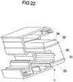
- the stiffening is effected by a plug-in composite profile (see FIGS. 22 to 25 ), in which the disadvantages are avoided from the point of view of the thermal insulation effect in comparison to a conventional U-reinforcing iron.
- a plug-in composite profile see FIGS. 22 to 25
- a composite profile on additional foam cover layers is that in the plastic window profile to be stiffened interior walls, which serve primarily to achieve a better thermal insulation effect, can be omitted.
- a 5-layer composite profile is largely adapted by, for example, milling the outer foam layers to the now larger main chamber of the plastic profile 10 so that hardly any cavities remain free. Since foams with a very low density have a better insulating effect than air-filled hollow chambers, the insulating effect of the plastic profile with inserted composite profile is higher despite lower number of chambers than in conventional plastic profiles with five to seven chambers.
- a particular advantage of this system is that the window profiles with fewer inner chambers have a lower weight per meter and, in addition, can be extruded faster because of the faster cooling, as a result of which these plastic profiles can be produced more cheaply. In Fig.
- extruded plastic profiles 10, 20 Pullastic hollow profile
- reinforcing elements 1, 2, designed here as reinforcing bands are reinforced.
- the reinforcing elements 1, 2 consist of a material (metal, GRP) with a relatively high modulus of elasticity.
- one of the reinforcing elements 1 of a relatively small hollow chamber 11 is arranged in the first plastic profile 10.
- the reinforcing elements 1, 2 are each arranged in a larger chamber 12.
- the plastic profiles 10 are e.g. extruded in a so-called cross-spray nozzle, wherein the reinforcing elements 1, 2 are fed through the nozzle in the extrusion direction.
- the edges of the reinforcing elements 1, 2 are connected in a shear-resistant manner in the longitudinal and transverse directions with the plastic profiles 10. This is e.g. achieved in that the edges of the reinforcing elements 1, 2 are positively embedded in the plastic. That is, the edges must have longitudinally-operative retaining elements 3, e.g. Undercuts have, which are filled with plastic during extrusion in the nozzle. Undercuts in the transverse direction, in the plane of the reinforcing strip, are provided so that the composite can not be released during long-term loading due to the effect of force and the influence of temperature.
- Fig. 1 has reinforcing elements 1, 2 in the form of ribbons.
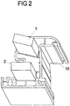
- Fig. 2 is a perspective view of a plastic profile 10 of a sash profile shown, in which the reinforcing elements 1, 2 are formed by wooden strips. The wood strips have a much greater thickness-to-widths Ratio, as the band-shaped reinforcing elements in Fig. 1 ,
- a wood reinforcement is possible, with which almost the same reinforcing effect is achieved, as by a reinforcement with conventional U-reinforcing iron.
- These wooden strips 1, 2 are also shear-resistant connected to the plastic profile 10 in order to develop the optimum reinforcing effect with respect to the neutral (bending) fiber.
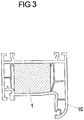
- a frame profile according to Fig. 3 shows that even a single wooden strip as a reinforcing element 1 in a plastic profile 10 is usable. It is not mandatory that the cross section of the wooden strip is rectangular. In this case, almost the entire main chamber of the plastic profile 10 is filled with a wood profile 1 adapted to the cross section. Due to the "large" wood cross section, this reinforcement also achieves a considerable stiffening effect.
- a shear-resistant integration in the plastic profile 10 can be made, but is not absolutely necessary in view of the reinforcing effect, because the neutral fiber of the wood reinforcement and those of the plastic profile 10 are close together due to geometry. That is, this reinforcement could just like the U-reinforcing iron inserted during the window assembly and bolted to the plastic profile. Likewise, sheathing and / or encapsulation of the wood reinforcement in the course of profile extrusion is possible.
- E-modules are to be understood here as mean values. It can be seen from the table that metallic reinforcing elements 1, 2 have the highest moduli of elasticity, followed by unidirectionally glass fiber reinforced plastics.
- the metals perform best. Likewise, this wood is very good. It is noticeable that in the case of short glass fiber reinforced thermoplastics, as well as in wood, the required thicknesses may be reduced. difficult to accommodate in the plastic profile 10, which is expected here with a significant reduction in the reinforcing effect compared to the metals. It also makes sense to use spruce wood as reinforcement. Taking the price into consideration, spruce wood is far superior to other materials, including fiberglass, and steel is the next.
- FIG. 4 to 19 different configurations of holding elements 3 are shown, which are arranged on reinforcing elements 1, 2. They are intended to produce a stronger connection between plastic profile 10 and reinforcing elements 1, 2, with a force effect in band plane being present both in the transverse and in the longitudinal direction.
- Fig. 4 is a partial view of an edge region of a reinforcing elements 1 is shown.
- the holding elements 3 are applied here by knurling and / or embossing. This is simply applicable especially to metallic reinforcing elements 1, 2.
- FIGS. 5 and 6 a further embodiment for holding elements 3 is shown.
- a band-shaped reinforcing element 1 preferably made of metal
- sawtooth structures are arranged as holding elements 3 on both edges.
- Fig. 6 presented an enlarged view of the sawtooth structure, showing the up and down bent saw teeth.
- the saw teeth are similar to the teeth of a hand saw and are also manufactured in such a way: punching out of gaps and cabinets of teeth, the teeth are alternately bent slightly to the left and right. This design causes a positive connection in two directions: in the longitudinal direction due to the tooth flanks and in the transverse direction as a result of the tooth pitch.
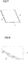
- FIGS. 7 and 8 an alternative embodiment is shown in which there is an edge formation of a reinforcing element 1 with alternately slightly bent left and right segments.
- this structure for a holding element 3 can also be generated by means of counter-acting wheels. These wheels run exactly in sync with each other and alternately have gaps and protrusions.
- the mutually acting edges cause a severing of the edges of the band-shaped reinforcing element 1, 2 similar as by means of a jar and the projections cause a slight bending of the resulting "teeth" alternately in both directions. Again, a positive connection is achieved after embedding the edge in plastic in the two main directions.
- Fig. 9 is an embodiment of a band-shaped reinforcing element 1, 2 shown, the edge formation is easy to produce: It is dispensed with the severing of the reinforcing element 1, 2. Only the edge of the reinforcing element 1, 2 is plastically deformed, eg wave-shaped. This is also done between two counteracting, synchronously running roles, the survey for a role in the direction of "shorter" than the gap of the counter-roller.
- This corrugated edge as a holding element 3 of the reinforcing element 1, 2 also leads to a shear-resistant connection, when it is tightly enclosed by plastic. It is advantageous that the supporting cross-section of the stiffening profile is not weakened by joints and thus contributes to the entire bandwidth for reinforcing the plastic profile.
- a further embodiment for a reinforcing element 1, 2 is shown, this embodiment is not limited to band-shaped reinforcing elements.
- the edge is provided with additional beads, which is easy to produce, especially when using aluminum by a rolling. By these beads, the positive connection in tensile stress in the transverse direction is higher load. For the form fit in the longitudinal direction, a combination with the tooth and wave training shown is recommended.
- Fig. 11 to 13 are different edge structures as holding elements 3 for reinforcing elements 1, 2 shown.
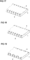
- Fig. 11 shows teeth with notched teeth for an undercut in the longitudinal and transverse directions according to the invention.
- FIG. 12 shows teeth with set teeth for undercut in the longitudinal and transverse directions according to the invention.
- the cutting direction for the teeth is not perpendicular to the edge of the reinforcing element 1, 2 but obliquely.
- the tooth forms according to Fig. 11 to 13 are recommended for metals which can be easily stamped and / or severed, for example aluminum.
- Fig. 14 is a reinforcing element 1, 2 shown in GRP.
- a material for reinforcing elements 1, 2 and glass fiber reinforced plastic is well.
- E modulus of the order of about 10,000 N / mm 2 can be achieved.
- Endless glass fiber reinforced plastics are more suitable, with the highest stiffnesses being achieved when using thermosetting plastics as binders in comparison to thermoplastics.
- Elasticity modules up to 40,000 N / mm 2 are foreseeable. In contrast to metals, in this case hardly any plastic deformation is possible for forming an edge as holding elements 3 with undercuts.
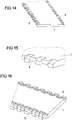
- Fig. 14 (and enlarged in Fig. 15 ) are, for example, by milling or grinding with diamond-tipped grinding wheels the desired Notches in the edges of the reinforcing element 1 generates. It does not depend on a specific assignment of the respective notches to each other or their exact geometry, so that the control of the various grinding wheels is also easy to do.
- such an edge structure as a holding element 3 is also possible with reinforcing elements 1, 2 made of other materials.
- Fig. 16 is another alternative, in particular for fasteners 1, 2 made of GRP, shown.
- fasteners 1, 2 made of GRP In order to form an undercut in the transverse direction, grooves are also ground longitudinally in addition to the teeth.
- reinforcing elements 1 made of wood, especially spruce wood, each having a notched edge.
- For wooden strips as reinforcing elements 1, 2 is an edge education by notches by means of saw or milling useful.
- Vertical cuts to the edge lead to a good anchoring against displacement in the longitudinal direction. Are these cuts obliquely to the longitudinal axis ( Fig. 19 ) or alternately obliquely backwards and forwards ( Fig. 18 ), also results in a very good connection against pulling in the transverse direction.
- the formation of the reinforcing elements 1, 2 was in the embodiments shown so far band-shaped or strip-shaped.
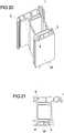
- FIGS. 20 and 21 a plastic profile is shown, in which four wires 1, 2, 4, 5 are arranged as reinforcing elements in the plastic profile 10.
- the wires 1, 2, 4, 5 can be made of steel or aluminum, for example.
- endless struts can unidirectional glass fiber reinforced plastics, are arranged in the plastic profile 10.
- the reinforcing elements 1, 2, 4, 5 are preferably arranged as far away as possible from the neutral fiber.
- FIGS. 20 and 21 It can be seen that the arrangement of the wires as reinforcing elements 1, 2, 4, 5 takes place substantially in the corners of the plastic profile 10.
- plastic profile 10 for windows allows the pressing of the reinforcements in the finished plastic profile 10.
- the wires 1, 2, 4, 5 can be useful in the context of profile extrusion, for example, following cooling, before the plastic profile 10 enters the caterpillar take, are pressed. However, they can also be pressed into the cut-to-length section bars or even into the frame sections cut to length and mitred for the purpose of making up the windows.
- wire 1, 2, 4, 5 is also heated to about 120 to 200 ° C in addition to embossing the surface. After pressing the heat is introduced into the adjacent plastic, this softens and becomes flowable and then fills the undercuts in the wire largely. After cooling, wire 1, 2, 4, 5 and plastic are optimally connected and it can be easily transferred large shear forces.
- reinforcing elements 1, 2, 4, 5 in which the reinforcing effect due to a shear-resistant connection by means of retaining elements 3 of inserted reinforcing elements (bands, strips wires) is effected with the plastic profile 10.
- At least one further foam layer (cover layers) 33, 34 is additionally glued to the force-effective tension / compression reinforcing belts. If U-reinforcing bars are used, they are 1-2 mm smaller than the chambers in hollow sections, so they need to be screwed. By using at least one cover layer 33, 34, a certain degree of oversize can easily be set, so that the reinforcement element can then be inserted without play into the plastic profile 10.
- the composite profile as reinforcing element 1, 2 according to FIGS. 22 to 25 has five layers 30, 31, 32, 33, 34.
- plastic profiles 10 For the application of such 5-layer composite profiles, it is expedient to simplify the plastic profiles 10, that is to make more extrusion-friendly (see FIGS. 24 and 25 ).
- These plastic profiles 10 have only three chambers, ie only two inner walls, which are required for the stability and function of the plastic profiles 10. Two or three inner chambers or inner walls have been eliminated compared to the original profile shape, which reduces the profile weight of the meter and allows a higher extrusion speed to be achieved. Nevertheless, the thermal insulation effect of the profile system is ultimately not diminished, because the outer foam layers of the composite profile 30, 31, 32, 33, 34 take over the Dämmfunktion the original inner chambers and even improve.
- the composite profiles as reinforcing elements 1, 2 for the frame profile after Fig. 24 or for the sash profile FIG. 25 arise by milling the foam components from the composite profile Fig. 23 .
- the "accuracy of fit" between PVC main profile and the foam portions of the composite profile 1 can be very tight. Slight spatial disabilities can be tolerated because the foam can be relatively easily sheared off and / or pushed in when inserting the reinforcing profile into the PVC profile along small projecting noses. That is, the reinforcing element 1 has a very close contact with the PVC profile and supports this immediately over a large area or at least linear.
- the screwing of the two plastic profiles 10 can therefore be simplified, ie it suffice less screws with larger distances from each other.
- the thermal insulation effect increases when the foam insert rests along several lines directly on the PVC profile, because no exchange of air over long distances can take place, the heat transfer due to convection is reduced.
- insulating foams are not to be introduced into the profile at the same time as the profile extrusion because the desired poor heat conduction considerably lengthens the calibration and cooling process and only a very limited foam specification can be used in the course of the extrusion process. It is more appropriate to optimize the processes for the foam production on the one hand and for the profile extrusion separately on the other hand and to bring together the respective semi-finished products.
- foam blanks In principle, it is possible to insert the foam blanks into the 6 m long profile bars or to insert them into the trimmed and mitered frame parts only in the course of the finishing process.
- a corresponding automatic production of the foam blanks and automatic introduction into the plastic profile 10 speaks rather for combining in the course of profile production. Complications during assembly are not to be expected then.
- Foams made of PS or PE have lower or equal melting points than PVC at approx. 200 ° C, so that they also soften when warming up for corner welding and can additionally act as a welding surface.
- the profile bars which are usually 6 m in length, cut off the lengths required to form the window frames by 45 °, mitred. From each four frame profiles then a rectangular frame is welded. The joining surfaces are first heated to the welding temperature, about 200 ° C, and then pressed together. Depending on the profile joining surface, this results in a burnup of approx. 3mm.
- "erosion” is not to be understood literally, that is, the softened plastic material deforms plastically and forms a bead, which is then removed again on the visible surfaces.
- the material of the reinforcing elements 1, 2 therefore also has an effect on the finishing process.
- the cutting process, the miter cutting, must be adapted to the material.
- no saw blades with carbide teeth are applicable.
- a cost-effective variant is available with cut-off loops.
- the remaining mentioned materials are to be separated almost without changing the process continues with the carbide circular saw blades.
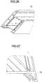
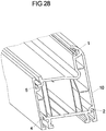
- Fig. 26 is a perspective view of a mitred plastic profile 10 with two reinforcing elements 1, 2, for example, made of aluminum or steel or GRP in band form.
- the resetting of the hard reinforcing elements 1, 2, 4, 5 is advantageously carried out immediately after the miter cutting, still in the same setting of the plastic profiles 10.
- the position of the plastic profile 10 and the cut surface is exactly known and fixed, so that by means of milling or sanding process the required area proportions can be edited exactly.
- This can be done by a shank or end mill, which, for example, program-controlled moves off the required contours.
- Well suited is a high-speed milling unit, since only small forces are transmitted to the workpiece and thus a flutter or vibration in the case of thin sheets is reduced.
- cutters with a comparatively small diameter are used in high-speed milling.
- Fig. 27 is the isolated (ie free-milled reinforcement element 1) shown.
- the cutter is aligned axially parallel to the plastic profile 10, via a suitable, programmable path control the required positions are approached.
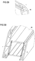
- a sawing or cut-off grinding method can be used, wherein in the miter plane through slots are formed with about 2 mm depth, as in Fig. 30 and 31 is shown. That is, in the plane of the reinforcing elements 1, 2 (designed here as a reinforcing strip), the plastic parts actually suitable for the welding process are removed. But this is not a disadvantage, since in the welding process these "gaps" in the course of the bead formation are filled up anyway with plastic from the adjacent areas.
- plastic profiles 10 according to this invention reinforced with reinforcing elements 1, 2, 4, 5 (bands of metal, strips, wires, etc.), these can also be used for the corner joint.
- the metal components can transmit locally much larger forces than the plastic, the required corner strength can be ensured that only these metal components are connected to each other durable.
- This connection can be done either by welding together or by gluing with an insert.
- the plastic itself does not have to be involved in the connection. This has the advantage that the plastic forms no Sch spawulst and this in the episode not painstakingly removed by the so-called "corner cleaning" and / or must be milled or pulled to a pleasing shape.
- the metal bands or wires are not reset against the miter surface, but themselves interconnected. This bonding can be done either mechanically or by welding.
- Welding e.g. Heat pulse welding similar to spot welding: The electrodes are applied to the externally accessible reinforcement elements 1, 2, 4, 5 (wires, bands, etc.) in the groove. If the miter surfaces are brought into contact, an electrically conductive connection is formed at the contact surface with great resistance - an arc arises at short notice, which leads to welding.
- Heat pulse welding similar to spot welding: The electrodes are applied to the externally accessible reinforcement elements 1, 2, 4, 5 (wires, bands, etc.) in the groove. If the miter surfaces are brought into contact, an electrically conductive connection is formed at the contact surface with great resistance - an arc arises at short notice, which leads to welding.
Landscapes
- Engineering & Computer Science (AREA)
- Civil Engineering (AREA)
- Structural Engineering (AREA)
- Wing Frames And Configurations (AREA)
- Extrusion Moulding Of Plastics Or The Like (AREA)
Claims (13)
- Profilé composite, en particulier pour des fenêtres et des portes, comprenant un profilé en plastique extrudé (10, 20) et au moins un élément de renforcement (1, 2, 4, 5) relié à celui-ci de manière essentiellement résistant à la poussée, au moins un élément de retenue (3) étant disposé sur l'élément de renforcement (1, 2, 4, 5) pour établir une liaison par engagement par liaison de matière, par friction et/ou par engagement par correspondance de formes entre l'élément de renforcement (1, 2, 4, 5) et le profilé en plastique (10), l'au moins un élément de retenue (3) agissant dans le plan de l'élément de renforcement (1, 2, 4, 5) à la fois dans la direction transversale et dans la direction longitudinale de l'élément de renforcement (1, 2, 4, 5),
caractérisé par
des structures de bord servant d'élément de retenue (3) pour l'élément de renforcement (1, 2) avec des dents comprenant des dents encochées en vue d'une contre-dépouille dans la direction longitudinale et transversale ou avec des dents comprenant des dents avoyées en vue d'une contre-dépouille dans la direction longitudinale et transversale, la direction de coupe pour les dents n'étant pas perpendiculaire au bord de l'élément de renforcement mais étant oblique. - Profilé composite selon la revendication 1,
caractérisé en ce que l'élément de renforcement (1, 2, 4, 5) se compose de métal, de préférence d'acier ou d'aluminium, de plastique renforcé par des fibres de verre, de préférence de duroplaste renforcé de manière unidirectionnelle, comme par exemple de la résine de polyester ou de la résine époxy insaturée, ou de bois, de préférence d'épicéa. - Profilé composite selon la revendication 1 ou 2,
caractérisé en ce que l'élément de retenue (3) présente un profilage, un moletage, une structure produite par des entailles et/ou par des estampages, une structure ondulée, une structure en dents de scie, une structure à encoches, un collage et/ou une zone pouvant être chauffée. - Profilé composite selon au moins l'une quelconque des revendications 1 à 3, caractérisé en ce que les encoches et/ou les entailles sont disposées en tant qu'éléments de retenue (3) transversalement et/ou obliquement par rapport à la direction longitudinale de l'élément de renforcement (1, 2, 4, 5).
- Profilé composite selon au moins l'une quelconque des revendications 1 à 4, caractérisé en ce que l'élément de renforcement (1, 2, 4, 5) est réalisé sous forme de bande, sous forme de baguette et/ou sous forme de fil métallique.
- Profilé composite selon au moins l'une quelconque des revendications précédentes, caractérisé en ce que l'effet d'isolation thermique et/ou la rigidité en flexion sont accrus par insertion de profilés composites préfabriqués (30, 31, 32, 33, 34) dans une ou plusieurs chambres.
- Profilé composite selon au moins l'une quelconque des revendications précédentes, caractérisé en ce que l'élément de renforcement (1, 2, 4, 5) fait partie d'un profilé composite ayant au moins quatre couches, à savoir une couche noyau en mousse (30), deux couches de recouvrement (31, 32) reliées à celle-ci de manière résistant à la poussée et ayant une grande rigidité, et au moins une couche (33, 34) en mousse isolante, qui est collée sur l'une des couches de recouvrement (31, 32).
- Procédé de fabrication d'un profilé composite selon au moins l'une quelconque des revendications 1 à 7, dans lequel au moins un élément de retenue (3) est réalisé par déformation plastique, en particulier par moletage ou gaufrage et/ou par façonnage, en particulier par roulage et/ou pressage de rainures ou d'ondulations.
- Procédé selon la revendication 8, caractérisé en ce que les éléments de renforcement (1, 2, 4, 5), sont introduits à travers une buse au cours de l'extrusion du profilé en plastique (10, 20) et sont incorporés dans le profilé en plastique (10, 20).
- Procédé selon la revendication 8 ou 9, caractérisé en ce que les éléments de renforcement (1, 2, 4, 5) sont pressés dans des rainures accessibles depuis l'extérieur dans le profilé en plastique (10, 20) seulement après le refroidissement substantiel du profilé en plastique (10, 20).
- Procédé selon au moins l'une quelconque des revendications 8 à 10, caractérisé en ce que pour la fabrication de fenêtres en plastique au moyen d'un procédé de soudage en angle, des éléments de renforcement incorporés (1, 2, 4, 5), après découpage à la longueur et coupe en onglet, sont en outre mis en retrait en une seule passe dans la scie à onglet par une opération de fraisage ou de sciage, afin de de ne pas gêner spatialement l'opération de soudage.
- Procédé selon au moins l'une quelconque des revendications 8 à 11, caractérisé en ce que lors de la fabrication de cadres de vantail et de dormants, les éléments de renforcement incorporés (1, 2, 4, 5) sont utilisés eux-mêmes de manière déterminante pour la connexion des angles, par le fait que ceux-ci sont reliés les uns aux autres par soudage et/ou par pressage dans une pièce d'insertion.
- Procédé selon au moins l'une quelconque des revendications 8 à 12, caractérisé en ce que les éléments de renforcement (1, 2, 4, 5), seulement lors de la confection de la fenêtre pour réaliser le cadre de vantail ou le dormant, sont pressés dans des rainures, accessibles depuis l'extérieur, des profilés en plastique et celles-ci s'étendent sans interruption autour d'au moins un coin du châssis formé, de manière à garantir une contribution à la liaison d'angle.
Priority Applications (2)
| Application Number | Priority Date | Filing Date | Title |
|---|---|---|---|
| SI201131588T SI2582901T1 (sl) | 2010-06-21 | 2011-06-16 | Kompozitni profil in postopek za izdelavo ojačilnega elementa za kompozitni profil |
| PL11730601T PL2582901T3 (pl) | 2010-06-21 | 2011-06-16 | Kształtownik kompozytowy i sposób wytwarzania elementu wzmacniającego dla kształtownika kompozytowego |
Applications Claiming Priority (2)
| Application Number | Priority Date | Filing Date | Title |
|---|---|---|---|
| DE102010030310A DE102010030310A1 (de) | 2010-06-21 | 2010-06-21 | Verbundprofil und Verfahren zur Herstellung eines Verstärkungselementes für ein Verbundprofil |
| PCT/EP2011/060030 WO2011161001A2 (fr) | 2010-06-21 | 2011-06-16 | Profilé composite et procédé de production d'un élément de renforcement pour le profilé composite |
Publications (2)
| Publication Number | Publication Date |
|---|---|
| EP2582901A2 EP2582901A2 (fr) | 2013-04-24 |
| EP2582901B1 true EP2582901B1 (fr) | 2018-07-18 |
Family
ID=44628275
Family Applications (1)
| Application Number | Title | Priority Date | Filing Date |
|---|---|---|---|
| EP11730601.9A Active EP2582901B1 (fr) | 2010-06-21 | 2011-06-16 | Profilé composite et procédé de production d'un élément de renforcement pour le profilé composite |
Country Status (10)
| Country | Link |
|---|---|
| EP (1) | EP2582901B1 (fr) |
| DE (1) | DE102010030310A1 (fr) |
| DK (1) | DK2582901T3 (fr) |
| ES (1) | ES2687179T3 (fr) |
| HU (1) | HUE040160T2 (fr) |
| PL (1) | PL2582901T3 (fr) |
| PT (1) | PT2582901T (fr) |
| RU (1) | RU2012156090A (fr) |
| SI (1) | SI2582901T1 (fr) |
| WO (1) | WO2011161001A2 (fr) |
Families Citing this family (6)
| Publication number | Priority date | Publication date | Assignee | Title |
|---|---|---|---|---|
| DE102013001625A1 (de) | 2012-09-30 | 2014-04-03 | Cepventures International Corp. | Verpackung für kantenempfindliches Transportgut |
| DE102013114710A1 (de) * | 2013-12-20 | 2015-06-25 | SCHÜCO International KG | Kunststofffenster- oder türrahmen und Verfahren zur Herstellung eines Kunststofffenster- oder türrahmens |
| DE102016005485A1 (de) | 2016-05-03 | 2017-11-23 | Glass Wrap Holding Corp. | Verpackung für kantenempfindliches Transportgut |
| DE102017003242A1 (de) | 2016-11-08 | 2018-07-05 | Glass-Wrap Holding Corporation | Verpackung für scheibenförmiges Transportgut wie Glas |
| CO2017011444A1 (es) * | 2017-11-07 | 2018-01-31 | Osorno Camilo Antonio Vargas | Perfiles lineales para marcos de puerta |
| CN114263666B (zh) * | 2022-01-06 | 2024-05-24 | 山东沃伦门窗有限公司 | 一种组角互锁连接件及使用方法 |
Family Cites Families (8)
| Publication number | Priority date | Publication date | Assignee | Title |
|---|---|---|---|---|
| GB1140261A (en) * | 1964-04-29 | 1969-01-15 | Elisa Berthelsen | Improvements in and relating to structural frames such as window frames |
| DE2061901A1 (de) * | 1970-12-16 | 1972-06-29 | Schley, Friedrich, 7800 Freiburg | Einspannvorrichtung für Kunststoff-Rahmen für Fenster und Türen, insbesondere aus Hart-PVC |
| DE3407639A1 (de) | 1984-03-01 | 1985-09-12 | Gebrüder Kömmerling Kunststoffwerke GmbH, 6780 Pirmasens | Verbundstab, insbesondere fuer fensterrahmen, tuerrahmen und rollaeden |
| JP3181819B2 (ja) * | 1995-11-10 | 2001-07-03 | 株式会社トクヤマ | 樹脂製窓枠 |
| DE19933099A1 (de) | 1999-07-15 | 2001-01-18 | Schueco Int Kg | Kunststoffhohlprofil mit eingelagerter Metallverstärkung, vorzugsweise Rahmenprofil für Fenster oder Türen |
| DE102005048992A1 (de) * | 2005-10-11 | 2007-04-12 | Helmut Over | Träger zum Aussteifen von Kunststoffhohlprofilen für Fenster- oder Türrahmen oder dergleichen |
| DE102008008343A1 (de) | 2008-02-08 | 2009-08-13 | Aluplast Gmbh | Profil für Fenster- oder Türrahmen |
| DE102008017879A1 (de) * | 2008-03-20 | 2009-09-24 | Sls Kunststoffverarbeitungs Gmbh & Co. Kg | Verfahren zum Herstellen von Kunststoff-Profilen mit Verstärkungseinlage und danach hergestellte Profile |
-
2010
- 2010-06-21 DE DE102010030310A patent/DE102010030310A1/de not_active Withdrawn
-
2011
- 2011-06-16 WO PCT/EP2011/060030 patent/WO2011161001A2/fr not_active Ceased
- 2011-06-16 SI SI201131588T patent/SI2582901T1/sl unknown
- 2011-06-16 PL PL11730601T patent/PL2582901T3/pl unknown
- 2011-06-16 RU RU2012156090/12A patent/RU2012156090A/ru not_active Application Discontinuation
- 2011-06-16 EP EP11730601.9A patent/EP2582901B1/fr active Active
- 2011-06-16 ES ES11730601.9T patent/ES2687179T3/es active Active
- 2011-06-16 PT PT11730601T patent/PT2582901T/pt unknown
- 2011-06-16 DK DK11730601.9T patent/DK2582901T3/en active
- 2011-06-16 HU HUE11730601A patent/HUE040160T2/hu unknown
Non-Patent Citations (1)
| Title |
|---|
| None * |
Also Published As
| Publication number | Publication date |
|---|---|
| PT2582901T (pt) | 2018-10-30 |
| RU2012156090A (ru) | 2014-07-27 |
| WO2011161001A2 (fr) | 2011-12-29 |
| WO2011161001A3 (fr) | 2012-04-26 |
| HUE040160T2 (hu) | 2019-02-28 |
| DK2582901T3 (en) | 2018-10-29 |
| PL2582901T3 (pl) | 2018-12-31 |
| SI2582901T1 (sl) | 2018-11-30 |
| EP2582901A2 (fr) | 2013-04-24 |
| ES2687179T3 (es) | 2018-10-24 |
| DE102010030310A1 (de) | 2011-12-22 |
Similar Documents
| Publication | Publication Date | Title |
|---|---|---|
| EP3712368B1 (fr) | Profilé de cadre d'un bâti dormant et/ou de cadre de battant ainsi que son procédé de fabrication | |
| EP2177702B1 (fr) | Profilé creux, notamment tuyau d'écartement pour un vitrage isolant et dispositif et procédé de fabrication du profilé creux | |
| EP2582901B1 (fr) | Profilé composite et procédé de production d'un élément de renforcement pour le profilé composite | |
| EP2483492B1 (fr) | Élément profilé de construction léger, à parois minces, formé à froid, et procédé de fabrication d'un tel élément profilé | |
| EP2467554B1 (fr) | Élément isolant en plusieurs parties, destiné à l'isolation thermique et disposé dans des profilés d'éléments de fenêtre, de porte et de façade, profilés pour des éléments de fenêtre, de porte et de façade, procédés de fabrication de l'élément isolant et du profilé | |
| EP1555376A1 (fr) | Profilé composite | |
| EP2557243A2 (fr) | Elément de construction destiné à l'isolation thermique | |
| EP2576949B1 (fr) | Profile a rupture de pont thermique | |
| DE202009006044U1 (de) | Stockrahmen und/oder Flügelrahmen | |
| EP2864567A1 (fr) | Moulure isolante pour un profilé composite destinée à des fenêtres, des portes ou des éléments de façade et procédé de fabrication d'une telle moulure isolante et d'un profilé composite comprenant une telle moulure isolante | |
| EP2586953B1 (fr) | Isolateur et profilé à isolation thermique | |
| DE2613402A1 (de) | Tuer- oder fensterrahmen aus kunststoff sowie verfahren zu seiner herstellung | |
| EP1347141B1 (fr) | Procédé de fabrication d'un profilé isolant | |
| EP2406454A1 (fr) | Ecarteur pour vitrages isolants | |
| EP2886779A1 (fr) | Cadre de porte ou de fenêtre en matière synthétique et procédé de fabrication d'un cadre de porte ou de fenêtre en matière synthétique | |
| DE2622905A1 (de) | Rolladenstab und verfahren zu seiner herstellung | |
| DE102009046554A1 (de) | Dämmleiste | |
| EP2454436B1 (fr) | Procédé de fabrication d'éléments portes ou fenêtres | |
| EP1154115A1 (fr) | Profilé creux remplissable par moussage | |
| DE10355913B4 (de) | Energieabsorptionselement | |
| EP3055476B1 (fr) | Profilé composite, bande de renforcement pour profilé composite et procédé permettant de produire un profilé composite | |
| WO2011104280A1 (fr) | Elément de renforcement pour des profilés de fenêtres en plastique et procédé pour sa fabrication | |
| EP1687549B1 (fr) | Element amortisseur | |
| EP3118388B1 (fr) | Jonction d'éléments de bâtiment avec une baguette en plastique et methode pour produire la baguette | |
| EP1785272B1 (fr) | Panneau léger et méthode pour sa fabrication |
Legal Events
| Date | Code | Title | Description |
|---|---|---|---|
| PUAI | Public reference made under article 153(3) epc to a published international application that has entered the european phase |
Free format text: ORIGINAL CODE: 0009012 |
|
| 17P | Request for examination filed |
Effective date: 20130116 |
|
| AK | Designated contracting states |
Kind code of ref document: A2 Designated state(s): AL AT BE BG CH CY CZ DE DK EE ES FI FR GB GR HR HU IE IS IT LI LT LU LV MC MK MT NL NO PL PT RO RS SE SI SK SM TR |
|
| DAX | Request for extension of the european patent (deleted) | ||
| 17Q | First examination report despatched |
Effective date: 20160901 |
|
| STAA | Information on the status of an ep patent application or granted ep patent |
Free format text: STATUS: EXAMINATION IS IN PROGRESS |
|
| GRAP | Despatch of communication of intention to grant a patent |
Free format text: ORIGINAL CODE: EPIDOSNIGR1 |
|
| STAA | Information on the status of an ep patent application or granted ep patent |
Free format text: STATUS: GRANT OF PATENT IS INTENDED |
|
| INTG | Intention to grant announced |
Effective date: 20180205 |
|
| GRAS | Grant fee paid |
Free format text: ORIGINAL CODE: EPIDOSNIGR3 |
|
| GRAA | (expected) grant |
Free format text: ORIGINAL CODE: 0009210 |
|
| STAA | Information on the status of an ep patent application or granted ep patent |
Free format text: STATUS: THE PATENT HAS BEEN GRANTED |
|
| AK | Designated contracting states |
Kind code of ref document: B1 Designated state(s): AL AT BE BG CH CY CZ DE DK EE ES FI FR GB GR HR HU IE IS IT LI LT LU LV MC MK MT NL NO PL PT RO RS SE SI SK SM TR |
|
| REG | Reference to a national code |
Ref country code: GB Ref legal event code: FG4D Free format text: NOT ENGLISH |
|
| REG | Reference to a national code |
Ref country code: CH Ref legal event code: EP |
|
| REG | Reference to a national code |
Ref country code: IE Ref legal event code: FG4D Free format text: LANGUAGE OF EP DOCUMENT: GERMAN |
|
| REG | Reference to a national code |
Ref country code: AT Ref legal event code: REF Ref document number: 1019551 Country of ref document: AT Kind code of ref document: T Effective date: 20180815 |
|
| REG | Reference to a national code |
Ref country code: DE Ref legal event code: R096 Ref document number: 502011014470 Country of ref document: DE |
|
| REG | Reference to a national code |
Ref country code: RO Ref legal event code: EPE Ref country code: CH Ref legal event code: NV Representative=s name: SCHMAUDER AND PARTNER AG PATENT- UND MARKENANW, CH |
|
| REG | Reference to a national code |
Ref country code: ES Ref legal event code: FG2A Ref document number: 2687179 Country of ref document: ES Kind code of ref document: T3 Effective date: 20181024 |
|
| REG | Reference to a national code |
Ref country code: DK Ref legal event code: T3 Effective date: 20181016 |
|
| REG | Reference to a national code |
Ref country code: PT Ref legal event code: SC4A Ref document number: 2582901 Country of ref document: PT Date of ref document: 20181030 Kind code of ref document: T Free format text: AVAILABILITY OF NATIONAL TRANSLATION Effective date: 20181002 |
|
| REG | Reference to a national code |
Ref country code: NL Ref legal event code: MP Effective date: 20180718 |
|
| REG | Reference to a national code |
Ref country code: LT Ref legal event code: MG4D |
|
| PG25 | Lapsed in a contracting state [announced via postgrant information from national office to epo] |
Ref country code: NL Free format text: LAPSE BECAUSE OF FAILURE TO SUBMIT A TRANSLATION OF THE DESCRIPTION OR TO PAY THE FEE WITHIN THE PRESCRIBED TIME-LIMIT Effective date: 20180718 |
|
| PG25 | Lapsed in a contracting state [announced via postgrant information from national office to epo] |
Ref country code: FI Free format text: LAPSE BECAUSE OF FAILURE TO SUBMIT A TRANSLATION OF THE DESCRIPTION OR TO PAY THE FEE WITHIN THE PRESCRIBED TIME-LIMIT Effective date: 20180718 Ref country code: IS Free format text: LAPSE BECAUSE OF FAILURE TO SUBMIT A TRANSLATION OF THE DESCRIPTION OR TO PAY THE FEE WITHIN THE PRESCRIBED TIME-LIMIT Effective date: 20181118 Ref country code: RS Free format text: LAPSE BECAUSE OF FAILURE TO SUBMIT A TRANSLATION OF THE DESCRIPTION OR TO PAY THE FEE WITHIN THE PRESCRIBED TIME-LIMIT Effective date: 20180718 Ref country code: SE Free format text: LAPSE BECAUSE OF FAILURE TO SUBMIT A TRANSLATION OF THE DESCRIPTION OR TO PAY THE FEE WITHIN THE PRESCRIBED TIME-LIMIT Effective date: 20180718 Ref country code: NO Free format text: LAPSE BECAUSE OF FAILURE TO SUBMIT A TRANSLATION OF THE DESCRIPTION OR TO PAY THE FEE WITHIN THE PRESCRIBED TIME-LIMIT Effective date: 20181018 Ref country code: GR Free format text: LAPSE BECAUSE OF FAILURE TO SUBMIT A TRANSLATION OF THE DESCRIPTION OR TO PAY THE FEE WITHIN THE PRESCRIBED TIME-LIMIT Effective date: 20181019 Ref country code: LT Free format text: LAPSE BECAUSE OF FAILURE TO SUBMIT A TRANSLATION OF THE DESCRIPTION OR TO PAY THE FEE WITHIN THE PRESCRIBED TIME-LIMIT Effective date: 20180718 |
|
| PG25 | Lapsed in a contracting state [announced via postgrant information from national office to epo] |
Ref country code: LV Free format text: LAPSE BECAUSE OF FAILURE TO SUBMIT A TRANSLATION OF THE DESCRIPTION OR TO PAY THE FEE WITHIN THE PRESCRIBED TIME-LIMIT Effective date: 20180718 Ref country code: HR Free format text: LAPSE BECAUSE OF FAILURE TO SUBMIT A TRANSLATION OF THE DESCRIPTION OR TO PAY THE FEE WITHIN THE PRESCRIBED TIME-LIMIT Effective date: 20180718 Ref country code: AL Free format text: LAPSE BECAUSE OF FAILURE TO SUBMIT A TRANSLATION OF THE DESCRIPTION OR TO PAY THE FEE WITHIN THE PRESCRIBED TIME-LIMIT Effective date: 20180718 |
|
| REG | Reference to a national code |
Ref country code: HU Ref legal event code: AG4A Ref document number: E040160 Country of ref document: HU |
|
| REG | Reference to a national code |
Ref country code: DE Ref legal event code: R097 Ref document number: 502011014470 Country of ref document: DE |
|
| PG25 | Lapsed in a contracting state [announced via postgrant information from national office to epo] |
Ref country code: CZ Free format text: LAPSE BECAUSE OF FAILURE TO SUBMIT A TRANSLATION OF THE DESCRIPTION OR TO PAY THE FEE WITHIN THE PRESCRIBED TIME-LIMIT Effective date: 20180718 Ref country code: EE Free format text: LAPSE BECAUSE OF FAILURE TO SUBMIT A TRANSLATION OF THE DESCRIPTION OR TO PAY THE FEE WITHIN THE PRESCRIBED TIME-LIMIT Effective date: 20180718 |
|
| PLBE | No opposition filed within time limit |
Free format text: ORIGINAL CODE: 0009261 |
|
| STAA | Information on the status of an ep patent application or granted ep patent |
Free format text: STATUS: NO OPPOSITION FILED WITHIN TIME LIMIT |
|
| PG25 | Lapsed in a contracting state [announced via postgrant information from national office to epo] |
Ref country code: SK Free format text: LAPSE BECAUSE OF FAILURE TO SUBMIT A TRANSLATION OF THE DESCRIPTION OR TO PAY THE FEE WITHIN THE PRESCRIBED TIME-LIMIT Effective date: 20180718 Ref country code: SM Free format text: LAPSE BECAUSE OF FAILURE TO SUBMIT A TRANSLATION OF THE DESCRIPTION OR TO PAY THE FEE WITHIN THE PRESCRIBED TIME-LIMIT Effective date: 20180718 |
|
| 26N | No opposition filed |
Effective date: 20190423 |
|
| PG25 | Lapsed in a contracting state [announced via postgrant information from national office to epo] |
Ref country code: MC Free format text: LAPSE BECAUSE OF FAILURE TO SUBMIT A TRANSLATION OF THE DESCRIPTION OR TO PAY THE FEE WITHIN THE PRESCRIBED TIME-LIMIT Effective date: 20180718 |
|
| PG25 | Lapsed in a contracting state [announced via postgrant information from national office to epo] |
Ref country code: LU Free format text: LAPSE BECAUSE OF NON-PAYMENT OF DUE FEES Effective date: 20190616 |
|
| PG25 | Lapsed in a contracting state [announced via postgrant information from national office to epo] |
Ref country code: HU Free format text: LAPSE BECAUSE OF NON-PAYMENT OF DUE FEES Effective date: 20200617 |
|
| PG25 | Lapsed in a contracting state [announced via postgrant information from national office to epo] |
Ref country code: CY Free format text: LAPSE BECAUSE OF FAILURE TO SUBMIT A TRANSLATION OF THE DESCRIPTION OR TO PAY THE FEE WITHIN THE PRESCRIBED TIME-LIMIT Effective date: 20180718 |
|
| PG25 | Lapsed in a contracting state [announced via postgrant information from national office to epo] |
Ref country code: MT Free format text: LAPSE BECAUSE OF FAILURE TO SUBMIT A TRANSLATION OF THE DESCRIPTION OR TO PAY THE FEE WITHIN THE PRESCRIBED TIME-LIMIT Effective date: 20180718 |
|
| PG25 | Lapsed in a contracting state [announced via postgrant information from national office to epo] |
Ref country code: MK Free format text: LAPSE BECAUSE OF FAILURE TO SUBMIT A TRANSLATION OF THE DESCRIPTION OR TO PAY THE FEE WITHIN THE PRESCRIBED TIME-LIMIT Effective date: 20180718 |
|
| PGFP | Annual fee paid to national office [announced via postgrant information from national office to epo] |
Ref country code: RO Payment date: 20220606 Year of fee payment: 12 Ref country code: PT Payment date: 20220615 Year of fee payment: 12 Ref country code: IE Payment date: 20220616 Year of fee payment: 12 Ref country code: DK Payment date: 20220623 Year of fee payment: 12 Ref country code: BG Payment date: 20220616 Year of fee payment: 12 |
|
| PGFP | Annual fee paid to national office [announced via postgrant information from national office to epo] |
Ref country code: SI Payment date: 20220606 Year of fee payment: 12 |
|
| PGFP | Annual fee paid to national office [announced via postgrant information from national office to epo] |
Ref country code: CH Payment date: 20220629 Year of fee payment: 12 |
|
| REG | Reference to a national code |
Ref country code: DE Ref legal event code: R081 Ref document number: 502011014470 Country of ref document: DE Owner name: EXELLIQ AUSTRIA GMBH, AT Free format text: FORMER OWNER: GREINER TOOL. TEC GMBH, NUSSBACH, AT |
|
| REG | Reference to a national code |
Ref country code: DK Ref legal event code: EBP Effective date: 20230630 |
|
| PG25 | Lapsed in a contracting state [announced via postgrant information from national office to epo] |
Ref country code: RO Free format text: LAPSE BECAUSE OF NON-PAYMENT OF DUE FEES Effective date: 20230616 Ref country code: PT Free format text: LAPSE BECAUSE OF NON-PAYMENT OF DUE FEES Effective date: 20231218 |
|
| REG | Reference to a national code |
Ref country code: CH Ref legal event code: PL |
|
| REG | Reference to a national code |
Ref country code: BE Ref legal event code: PD Owner name: EXELLIQ AUSTRIA GMBH; AT Free format text: DETAILS ASSIGNMENT: CHANGE OF OWNER(S), ASSIGNMENT; FORMER OWNER NAME: EXELLIQ HOLDING GMBH Effective date: 20240111 Ref country code: BE Ref legal event code: HC Owner name: EXELLIQ HOLDING GMBH; AT Free format text: DETAILS ASSIGNMENT: CHANGE OF OWNER(S), CHANGE OF OWNER(S) NAME; FORMER OWNER NAME: GREINER TOOL. TEC GMBH Effective date: 20240111 |
|
| REG | Reference to a national code |
Ref country code: GB Ref legal event code: 732E Free format text: REGISTERED BETWEEN 20240201 AND 20240207 |
|
| REG | Reference to a national code |
Ref country code: IE Ref legal event code: MM4A |
|
| REG | Reference to a national code |
Ref country code: SI Ref legal event code: KO00 Effective date: 20240222 |
|
| PG25 | Lapsed in a contracting state [announced via postgrant information from national office to epo] |
Ref country code: IE Free format text: LAPSE BECAUSE OF NON-PAYMENT OF DUE FEES Effective date: 20230616 |
|
| PG25 | Lapsed in a contracting state [announced via postgrant information from national office to epo] |
Ref country code: IE Free format text: LAPSE BECAUSE OF NON-PAYMENT OF DUE FEES Effective date: 20230616 Ref country code: CH Free format text: LAPSE BECAUSE OF NON-PAYMENT OF DUE FEES Effective date: 20230630 |
|
| PG25 | Lapsed in a contracting state [announced via postgrant information from national office to epo] |
Ref country code: SI Free format text: LAPSE BECAUSE OF NON-PAYMENT OF DUE FEES Effective date: 20230617 |
|
| PG25 | Lapsed in a contracting state [announced via postgrant information from national office to epo] |
Ref country code: SI Free format text: LAPSE BECAUSE OF NON-PAYMENT OF DUE FEES Effective date: 20230617 |
|
| PG25 | Lapsed in a contracting state [announced via postgrant information from national office to epo] |
Ref country code: DK Free format text: LAPSE BECAUSE OF NON-PAYMENT OF DUE FEES Effective date: 20230630 |
|
| REG | Reference to a national code |
Ref country code: AT Ref legal event code: PC Ref document number: 1019551 Country of ref document: AT Kind code of ref document: T Owner name: EXELLIQ AUSTRIA GMBH, AT Effective date: 20240603 |
|
| PG25 | Lapsed in a contracting state [announced via postgrant information from national office to epo] |
Ref country code: DK Free format text: LAPSE BECAUSE OF NON-PAYMENT OF DUE FEES Effective date: 20230630 |
|
| PG25 | Lapsed in a contracting state [announced via postgrant information from national office to epo] |
Ref country code: BG Free format text: LAPSE BECAUSE OF NON-PAYMENT OF DUE FEES Effective date: 20230616 |
|
| REG | Reference to a national code |
Ref country code: ES Ref legal event code: PC2A Owner name: EXELLIQ AUSTRIA GMBH Effective date: 20241112 |
|
| PG25 | Lapsed in a contracting state [announced via postgrant information from national office to epo] |
Ref country code: BG Free format text: LAPSE BECAUSE OF NON-PAYMENT OF DUE FEES Effective date: 20230616 |
|
| PGFP | Annual fee paid to national office [announced via postgrant information from national office to epo] |
Ref country code: PL Payment date: 20250520 Year of fee payment: 15 Ref country code: DE Payment date: 20250403 Year of fee payment: 15 |
|
| PGFP | Annual fee paid to national office [announced via postgrant information from national office to epo] |
Ref country code: GB Payment date: 20250620 Year of fee payment: 15 |
|
| PGFP | Annual fee paid to national office [announced via postgrant information from national office to epo] |
Ref country code: BE Payment date: 20250617 Year of fee payment: 15 |
|
| PGFP | Annual fee paid to national office [announced via postgrant information from national office to epo] |
Ref country code: FR Payment date: 20250626 Year of fee payment: 15 |
|
| PGFP | Annual fee paid to national office [announced via postgrant information from national office to epo] |
Ref country code: AT Payment date: 20250616 Year of fee payment: 15 |
|
| PGFP | Annual fee paid to national office [announced via postgrant information from national office to epo] |
Ref country code: TR Payment date: 20250613 Year of fee payment: 15 |
|
| PGFP | Annual fee paid to national office [announced via postgrant information from national office to epo] |
Ref country code: ES Payment date: 20250718 Year of fee payment: 15 |
|
| PGFP | Annual fee paid to national office [announced via postgrant information from national office to epo] |
Ref country code: IT Payment date: 20250630 Year of fee payment: 15 |