EP2620676A2 - Verbesserungen bei oder in Zusammenhang mit Flüssigkeitsdichtungen - Google Patents
Verbesserungen bei oder in Zusammenhang mit Flüssigkeitsdichtungen Download PDFInfo
- Publication number
- EP2620676A2 EP2620676A2 EP13160828.3A EP13160828A EP2620676A2 EP 2620676 A2 EP2620676 A2 EP 2620676A2 EP 13160828 A EP13160828 A EP 13160828A EP 2620676 A2 EP2620676 A2 EP 2620676A2
- Authority
- EP
- European Patent Office
- Prior art keywords
- fluid seal
- sintered
- seal
- engine
- sealing
- Prior art date
- Legal status (The legal status is an assumption and is not a legal conclusion. Google has not performed a legal analysis and makes no representation as to the accuracy of the status listed.)
- Withdrawn
Links
Images




Classifications
-
- B—PERFORMING OPERATIONS; TRANSPORTING
- B22—CASTING; POWDER METALLURGY
- B22F—WORKING METALLIC POWDER; MANUFACTURE OF ARTICLES FROM METALLIC POWDER; MAKING METALLIC POWDER; APPARATUS OR DEVICES SPECIALLY ADAPTED FOR METALLIC POWDER
- B22F3/00—Manufacture of workpieces or articles from metallic powder characterised by the manner of compacting or sintering; Apparatus specially adapted therefor ; Presses and furnaces
- B22F3/24—After-treatment of workpieces or articles
-
- B—PERFORMING OPERATIONS; TRANSPORTING
- B22—CASTING; POWDER METALLURGY
- B22F—WORKING METALLIC POWDER; MANUFACTURE OF ARTICLES FROM METALLIC POWDER; MAKING METALLIC POWDER; APPARATUS OR DEVICES SPECIALLY ADAPTED FOR METALLIC POWDER
- B22F5/00—Manufacture of workpieces or articles from metallic powder characterised by the special shape of the product
-
- C—CHEMISTRY; METALLURGY
- C23—COATING METALLIC MATERIAL; COATING MATERIAL WITH METALLIC MATERIAL; CHEMICAL SURFACE TREATMENT; DIFFUSION TREATMENT OF METALLIC MATERIAL; COATING BY VACUUM EVAPORATION, BY SPUTTERING, BY ION IMPLANTATION OR BY CHEMICAL VAPOUR DEPOSITION, IN GENERAL; INHIBITING CORROSION OF METALLIC MATERIAL OR INCRUSTATION IN GENERAL
- C23C—COATING METALLIC MATERIAL; COATING MATERIAL WITH METALLIC MATERIAL; SURFACE TREATMENT OF METALLIC MATERIAL BY DIFFUSION INTO THE SURFACE, BY CHEMICAL CONVERSION OR SUBSTITUTION; COATING BY VACUUM EVAPORATION, BY SPUTTERING, BY ION IMPLANTATION OR BY CHEMICAL VAPOUR DEPOSITION, IN GENERAL
- C23C8/00—Solid state diffusion of only non-metal elements into metallic material surfaces; Chemical surface treatment of metallic material by reaction of the surface with a reactive gas, leaving reaction products of surface material in the coating, e.g. conversion coatings, passivation of metals
- C23C8/06—Solid state diffusion of only non-metal elements into metallic material surfaces; Chemical surface treatment of metallic material by reaction of the surface with a reactive gas, leaving reaction products of surface material in the coating, e.g. conversion coatings, passivation of metals using gases
- C23C8/08—Solid state diffusion of only non-metal elements into metallic material surfaces; Chemical surface treatment of metallic material by reaction of the surface with a reactive gas, leaving reaction products of surface material in the coating, e.g. conversion coatings, passivation of metals using gases only one element being applied
- C23C8/10—Oxidising
- C23C8/16—Oxidising using oxygen-containing compounds, e.g. water, carbon dioxide
- C23C8/18—Oxidising of ferrous surfaces
-
- B—PERFORMING OPERATIONS; TRANSPORTING
- B22—CASTING; POWDER METALLURGY
- B22F—WORKING METALLIC POWDER; MANUFACTURE OF ARTICLES FROM METALLIC POWDER; MAKING METALLIC POWDER; APPARATUS OR DEVICES SPECIALLY ADAPTED FOR METALLIC POWDER
- B22F3/00—Manufacture of workpieces or articles from metallic powder characterised by the manner of compacting or sintering; Apparatus specially adapted therefor ; Presses and furnaces
- B22F3/24—After-treatment of workpieces or articles
- B22F2003/247—Removing material: carving, cleaning, grinding, hobbing, honing, lapping, polishing, milling, shaving, skiving, turning the surface
-
- B—PERFORMING OPERATIONS; TRANSPORTING
- B22—CASTING; POWDER METALLURGY
- B22F—WORKING METALLIC POWDER; MANUFACTURE OF ARTICLES FROM METALLIC POWDER; MAKING METALLIC POWDER; APPARATUS OR DEVICES SPECIALLY ADAPTED FOR METALLIC POWDER
- B22F2999/00—Aspects linked to processes or compositions used in powder metallurgy
Definitions
- the present invention is concerned with improvements in or relating to fluid seals and particularly, but not exclusively, to a method of manufacturing a part or component that has a surface capable of providing a fluid seal in use and to a part manufactured using such a method.
- the invention may find advantageous application in the manufacturing of rotating parts for vehicle engines that provide such fluid sealing surfaces. Aspects of the invention relate to a method, to a part, to a fluid seal surface, to a product, to a sealing arrangement and to a vehicle.
- the connecting part is typically provided with a sealing member or gasket typically formed from a plastics or polymeric material such as rubber. Any unevenness on the surface abutting the sealing member will result in the premature deterioration of the plastics or rubber seal.
- a sealing member or gasket typically formed from a plastics or polymeric material such as rubber. Any unevenness on the surface abutting the sealing member will result in the premature deterioration of the plastics or rubber seal.
- Many engine sub-systems are supplied as sealed units and, in these circumstances, it may not be possible to replace a damaged rubber seal. Instead, the entire sub-system must be replaced. Unevenness on the surface abutting the rubber seal may therefore decrease the effective lifetime of the sub-system as a whole. This may also adversely affect other sub-systems or components of the engine due to oil or coolant loss.
- a fluid seal arrangement (17) comprising a sealing member formed from a plastics or polymeric material and a part in sealing cooperation therewith, wherein the part is characterised by a body (10) formed from a sintered ferrous material having at least one surface (5) arranged to provide a fluid seal (17), in use, characterised in that the at least one surface (5)comprises an un-ground surface of the ferrous material coated with a layer of Fe304 wherein the part comprises one of a coupling (10) for a fuel injector (15), a viscous fan (70) for a cooling system of an internal combustion engine, a water pump (80), an oil seal retainer (90) for use in sealing the ends of a crankshaft (91), differential transmission, gearbox, axle, driveshaft (82, 92, 102), hub (13) or transfer case; and a vacuum pump (110) for use in the braking system of a vehicle.
- a coupling 10 for a fuel injector (15), a viscous fan (70) for a cooling system of an
- un-ground surface as used herein is intended to mean a surface of the ferrous part which has been created by direct contact with the sintering tool and has not been subject to any further smoothing or polishing process, such as grinding, abrading or machining. This surface is also known as a raw surface or virgin surface of the part.
- the performance of the part depends critically on the tolerances of each individual face. As each face has to be machined separately, each one could be subject to an error in the positioning of the grinding machine.
- the sintering process of the present invention is a single step of sintering to produce the majority of the facets of the part. This results in a much more reliable process.
- a method of manufacturing a sintered ferrous part having at least one surface configured to provide a fluid seal comprising depositing a layer of Fe 3 O 4 onto an un-ground surface of the part to as to form the at least one fluid sealing surface.
- a method of forming a fluid seal surface on a sintered ferrous part comprising depositing a layer of Fe 3 O 4 onto an un-ground surface of the sintered ferrous part so as to form the fluid seal surface.
- the method comprises forming the part from a sintered ferrous material before depositing the Fe 3 O 4 layer.
- depositing the Fe 3 O 4 layer comprises steam treating at least the un-ground surface of the part.
- the entire part may be subjected to steam treatment so as to deposit the layer substantially fully thereover.
- a sintered ferrous part having at least one surface arranged to provide a fluid seal, in use, wherein the at least one surface comprises an un-ground surface of ferrous material coated with a layer of Fe 3 O 4 .
- a method of manufacturing a moving part capable of providing a liquid seal comprising the steps of forming the part from sintered steel and forming a layer of Fe 3 O 4 to provide a surface finish on the sintered part that is capable of providing a liquid seal.
- a moving part providing a liquid seal for use in a vehicle engine, the part comprising a sintered body and a steam treated surface finish for providing the liquid seal.
- the moving part may be a rotating part.
- the method may comprise the step of machining complex structures, such as keyways, and screw threads within the part. These structures may be created separately from the sintering step since they generally do not include the surfaces that provide a liquid seal.
- the part may be, inter alia, a coupling for an injection pump for a fuel injection unit in a diesel engine, a viscous fan from a radiator system of an internal combustion engine, a water pump for use in an internal combustion engine, an oil seal retainer for use in closing the ends of a vehicle crankshaft, an oil seal retainer for sealing a differential transmission, gearbox or transfer case or a vacuum pump for use in the braking system of a vehicle.
- a coupling for an injection pump for a fuel injection unit in a diesel engine a viscous fan from a radiator system of an internal combustion engine, a water pump for use in an internal combustion engine, an oil seal retainer for use in closing the ends of a vehicle crankshaft, an oil seal retainer for sealing a differential transmission, gearbox or transfer case or a vacuum pump for use in the braking system of a vehicle.
- Sintering is a known method for making objects from a suitable material, usually a ceramic or metallic powder, by heating the material (below its melting point) until its particles adhere to each other and then applying pressure to the material by compressing it in a sintering tool.
- the sintering tool typically takes the form of a rigid metallic block with an internal cavity or void corresponding in shape to the desired final part.
- the sintering tool operates in a manner similar to that of a moulding tool whereby the material is forced into the mould cavity at high pressure so as to ensure that the material flows evenly into each void of the tool cavity. Once the material has cooled and set, the sintering tool is opened and the part removed.
- Sintered bronze is traditionally used for manufacturing ceramic objects and sintered bronze is frequently used as a material for bearings.
- Sintered bronze is suitable for use in bearings since its porosity allows lubricants to flow through it.
- sintering is used when there is no alternative manufacturing technique.
- the designer of a metallic part may decide to use sintering over casting or billet machining for several reasons.
- the desired part may require a particular crystalline structure which cannot always be achieved with casting.
- the part may be desired in large numbers and so the percentage of material wastage associated with billet machining may not be cost effective.
- the dimensional tolerance of the part may be critical between two or more features of the part.
- Sintering produces parts with dimensional accuracy close to the original sintering tool with excellent repeatability. Some design features may not be created easily by sintering such as screw threads but once a part has been sintered further processes may be employed to achieve the desired final shape. Once a part has been sintered it may be machined, ground or cut as required to create surface features that cannot be formed by sintering alone.
- the function of a part may be enhanced if it is porous. For example if a part is bathed in lubricant, some of the lubricant will be trapped by the open pores of the sintered part which reduces wear. However, the porosity of ferrous sintered parts make them prone to corrosion if the part is exposed to water which may be unsuitable for some applications.
- the surface of the sintered ferrous part created by the direct contact between the metallic powder forced into the tool and the surface of the tool cavity walls is known as the raw or virgin surface.
- the raw or virgin surface of the sintered part has not been subjected to any further smoothing and/or polishing treatment, such as machining, abrading or grinding, after removal from the sintering tool, and for this reason is referred to hereafter as the "un-ground surface".
- the un-ground surface tends not to be particularly hard-wearing and may be porous. If the final part must be non-porous or if greater durability is required then the ferrous part may require further surface treatment after sintering.
- Steam treatment is a term of art referring generally to a coating technique that is typically employed when a part needs to be hardened. When handling ferrous parts, the technique generally results in the deposition of a uniform layer of Fe 3 O 4 , or "black iron" on the treated surface or surfaces of the part.
- Fe 3 O 4 is a crystalline solid, meaning that a surface formed from Fe 3 O 4 is hard and has a low porosity.
- This deposition layer of Fe 3 O 4 is typically 2 - 10 ⁇ m in thickness, but this may vary due to the quality of the un-ground surface or production process parameters such as temperature and duration of exposure to the steam.
- the resulting part has a black appearance and, in addition to an increased hardness, is also more resistant to corrosion than a similar part that has not been so treated.
- the surface of a sintered ferrous part with a coating of Fe 3 O 4 is far less porous as the Fe 3 O 4 crystals are very fine and has the effect of uniformly filling the pores, especially in the crystalline surface structure of the sintered part.
- Steam treatment does not simply block the pores, but also increases the corrosion resistance and alters the mechanical properties, thus increasing the density, the hardness and the tensile strength of the sintered part and thus improving wear properties.
- any machining or grinding process has to be carefully monitored to ensure sufficient repeatability and dimensional tolerances between features of the part such as mounting points and fluid seals.
- the final shape of the part is achieved directly from the tool, thereby requiring fewer manufacturing operations and advantageously providing tighter dimensional tolerances.
- the deposition of Fe 3 O 4 directly onto the un-ground surface of the sintered ferrous part for example by means of steam treating, produces a surface that is sufficiently smooth, durable and non-porous to form a reliable fluid seal without the need for additional machining or grinding processes.
- Figures 1 to 5 show a coupling 10 for the type of fuel pump used in a diesel engine.
- the coupling 10 is fabricated from, for example, M1040 steel.
- the grade of steel is chosen to be suitable for the particular application. The choice is a compromise between cost and weight to produce a part suitable for the mechanical loads whilst still providing a sufficient safety margin.
- the coupling 10 is shown in isolation in Figures 1, 2 and 3 .
- the coupling 10 comprises a flange 12 and a boss or hub 13.
- the flange and hub 13 both have a circular cross-section.
- the manufacturing tolerance on the diameter of the hub 13 is extremely tight to ensure that the coupling 10 is capable of interfacing to provide an effective seal.
- a fluid seal surface 5 is provided around the outer surface of the hub 13.
- Figure 4 shows the coupling 10 in the context of a fuel pump system 15 including a fuel pump 18.
- Figure 5 contextualises the fuel pump system 15 within the engine as a whole.
- the coupling 10 is driven to rotate by the insertion of a shaft 16 into a keyed conical hole 11 with a keyway 19.
- the shaft 16 is also keyed and rotation results when a key is provided in joining the respective keyways 19.
- the hole 11 tapers through the hub 13 and at least partially through the flange 12.
- the coupling separates a liquid filled area A from a non-liquid filled area B.
- the seal is provided on the liquid filled side A of the coupling 10, by a rubber sealing member 17 which is seated on the fluid seal surface 5 of hub 13.
- Holes 14 are provided through the flange 12 to enable the coupling 10 to interface with other engine parts in the non-liquid filled area B.
- the coupling 10 is manufactured in a three-step process: firstly, the body of the part is formed by sintering; next, the holes 14 in the flange 12 are tapped in known manner; finally, the entire part is steam treated to form the Fe 3 O 4 coating.
- the steam treatment is used to harden the surface, reduce porosity and improve the corrosion resistance of the part.
- an additional grinding step would be performed on the part before the part is subjected to the steam treatment in order to provide a surface that is sufficiently smooth to provide a liquid seal.
- the present applicants have identified that the operation of steam treating the surface obviates the need for any grinding.
- the cross-section of a machined part consists of a series of regularly spaced and shaped peaks.
- the surface resulting from the steam treatment has an almost completely smooth surface with occasional microscopic peaks that result from random positioning of crystals.
- the smooth surface results in a much larger proportion of the surface area being available for interfacing with the seal.
- the occasional peaks are typically worn away by the interfacing part before any damage occurs to that part.
- the smooth surface provides an advantage for the lifetime of the seal.
- the smooth outer surface of the hub 13 provides the fluid seal surface 5 and ensures that damage to the seal 17 is reduced, thus increasing the effective life of the fuel pump system 15.
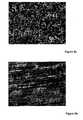
- Figures 6a to 6e show a series of 30X magnification view of sintered parts with or without machining, pre- and post-durability testing.
- Figure 6a shows a sintered part at 30X magnification.
- the porous surface is readily apparent. This surface can be made more uniform by machining, as shown in Figure 6b . This provides a good surface finish, but the surface is porous and is therefore unsuitable for providing a liquid seal.
- Figure 6c shows a non-machined sintered part that has been subjected to durability testing. The wear apparent on the surface is typical of that expected in such a test.
- Figure 6d shows the sintered part of Figure 6a when it has been steam treated, i.e. in accordance with an embodiment of the present invention.
- the surface is very smooth and non-porous.
- the surface also has a very high surface hardness.
- Figure 6e shows the part from Figure 6d once it has been subjected to a durability test. It will be readily apparent that the wear is reduced in comparison with the sintered part shown in Figure 6c which had not been steam-treated.
- Figure 7 shows a viscous-drive 70 for a cooling fan for an internal combustion engine cooling system.
- the viscous-drive 70 transmits drive to a cooling fan (not shown) from the engine in response to changes in the ambient air temperature surrounding the body of the viscous-drive.
- the viscous-drive 70 comprises a housing 71, a bi-metallic controller (not shown), an input shaft (not shown) and an output shaft 72.
- the input and output shafts 72 are separated by the viscous-drive 70.
- the housing 71 is secured to the engine or radiator by means of a suitable bracket.
- the housing 71 is positioned so as to be in the direct path of the air-flow from the cooling fan mounted to the radiator.
- the housing 71 is designed to transmit any changes in the air temperature to the bi-metallic controller housed within the housing 71.
- the periphery of the housing is typically provided with a plurality of fins 73 to increase the surface area to optimise the controller's response to air temperature change.
- the housing 71 further comprises at least two internal chambers (not shown), one accommodating the input shaft and one accommodating the output shaft 72. Fluid communication between the two chambers is via a valve (not shown) which is operated by the controller and a return orifice.
- the input shaft has a first input or driven end and distal from the input end a plurality of vanes.
- the output shaft 72 has a driven end surrounded by a plurality of vanes. Distal from the driven end there is a drive end which is connected to the cooling fan.
- the vanes of the input and output shafts are surrounded by a viscous fluid contained within the housing. Fluid communication between the first and second chamber is permitted only via the control valve and the return orifice.
- the input shaft is driven by the engine, typically via a belt and pulley. There is no communication of drive from the input shaft to the output shaft if the engine temperature is too low as the bi-metallic controller holds the valve closed.
- the bi-metallic controller opens the valve, allowing a circuit of fluid communication between the two chambers.
- a viscous fluid in the first chamber may then pass from the first chamber to the second via the valve, applying a force to the drive vanes on the output shaft and causing the fan to turn. Oil returns to the first chamber via the return orifice thus creating a fluid circuit.
- a reliable seal must be provided between the housing and the input and output shafts to prevent a loss of fluid which would be detrimental to performance.
- FIGS 8a and 8b show, respectively, the exterior and interior of a water pump 80 for an internal combustion engine cooling system.
- the water pump 80 is used to pump coolant around the engine and between the engine and the heat exchanger or radiator.
- the water pump 80 comprises a housing 81, a drive shaft 82 and an impeller 83.
- the impeller 83 is connected to the drive shaft 82 which is driven by the engine.
- the drive shaft 82 rotates on bearings and must have a reliable fluid seal between the drive shaft 82 and the housing 81 to prevent loss of coolant or the fluid communication of coolant on one side of the housing 81 and engine lubricant on the other side of the housing 81 which would be detrimental to the engine.
- Figure 9 shows an oil seal retainer 90 designed to be affixed to an end of the crankshaft 91 of a vehicle.
- An engine crankshaft 91 is provided with a primary output end (not shown) and distal from the primary output end is a secondary output end 92 or ancillary drive end. The output from the engine is taken from the primary output end of the crankshaft 91 which drives the vehicle via a gearbox.
- engine ancillaries such as power steering pumps, cooling fans, alternators, air conditioning compressors and vacuum pumps are driven by the crankshaft 91 via a pulley and serpentine belt system from the secondary output 92.
- crankshaft 91 is supported by bearings within a crankcase (not shown) which contains lubricating oil for the crankshaft 91 and the other moving parts of the engine.
- the pulley for the ancillary drive is mounted on the end 92 of the crankshaft 91 that is supported by bearings in the crankcase and protrudes through the crankcase to outside of the engine.
- a reliable oil seat is vital at the point where the crankshaft 91 protrudes through the end bearings of the crankcase to support the pulley, to prevent the loss of lubricating oil from the crankcase.
- Figure 10 shows an oil seal retainer 100 for sealing differential transmission systems, gearboxes and transfer cases. These devices supply drive torque from an engine to the road wheels of a motor vehicle.
- Such devices typically comprise a housing 101, gears mounted on rotating shafts 102 supported by bearings set into the housing 101.
- the rotating parts require lubrication which is typically provided by a lubricant such as oil contained within the housing 101.
- Rotating shafts 102 often need to protrude from the housing 101 in order to receive drive from the engine or another gear drive, or to output drive to the road wheels or another gear drive.
- the housing 101 not only provides suitable support for the bearings that carry the rotating shafts 102, but also serves to contain lubricating oil and keep out foreign bodies such as dirt that could damage the gears.
- FIG 11 shows a vacuum pump 110 for the braking system of a motor vehicle.
- the vacuum pump 110 is typically driven via a pulley driven by a serpentine belt on the side of the vehicle engine.
- the vacuum pump 110 typically comprises a housing 111, a drive shaft 112 and an impeller (not shown).
- the impeller is connected to the drive shaft 112 which is driven by the drive pulley on the outside of the housing 111.
- the drive shaft 112 rotates on bearings and must have a reliable fluid seal between the drive shaft 112 and the housing 111 to prevent loss of vacuum or lubricant. The loss of vacuum or lubricant would be detrimental to the performance of the braking system.
- the rotating parts designed to provide liquid seals in each of the systems illustrated in Figures 7 to 11 respectively can be made using a two-step process of creating the part by sintering and then steam treating the sintered part in order to deposit a layer of Fe 3 O 4 that creates a surface that is sufficiently smooth, non-porous and durable to provide the liquid seal without requiring machining or any additional surfaces to create the seal.
- a third, machining step is required only to create any internal shapes such as screw-threads or keyways that cannot be created using sintering, which step can be carried out before or after the step of steam treating the part.
- the present invention provides a surface quality on the steam treated sintered part that greatly enhances the service life of the sealing member, this is especially the case for polymeric sealing members.
- the present invention provides a durable sealing surface as shown in Figure 6 . The improvement in durability of both the fluid seal surface of the sintered part and the sealing member greatly enhances reliability and reduces service cost and complexity.
Landscapes
- Engineering & Computer Science (AREA)
- Mechanical Engineering (AREA)
- Chemical & Material Sciences (AREA)
- Manufacturing & Machinery (AREA)
- Chemical Kinetics & Catalysis (AREA)
- Materials Engineering (AREA)
- Metallurgy (AREA)
- Organic Chemistry (AREA)
- Powder Metallurgy (AREA)
- Mechanical Sealing (AREA)
- Sealing Devices (AREA)
Applications Claiming Priority (2)
| Application Number | Priority Date | Filing Date | Title |
|---|---|---|---|
| GB0704019A GB2447029A (en) | 2007-03-02 | 2007-03-02 | Sintered steel component with layer of Fe3O4 |
| EP08717309A EP2115332A1 (de) | 2007-03-02 | 2008-03-03 | Verbesserung an oder in zusammenhang mit fluiddichtungen |
Related Parent Applications (1)
| Application Number | Title | Priority Date | Filing Date |
|---|---|---|---|
| EP08717309.2 Division | 2008-03-03 |
Publications (2)
| Publication Number | Publication Date |
|---|---|
| EP2620676A2 true EP2620676A2 (de) | 2013-07-31 |
| EP2620676A3 EP2620676A3 (de) | 2013-10-30 |
Family
ID=37965773
Family Applications (2)
| Application Number | Title | Priority Date | Filing Date |
|---|---|---|---|
| EP13160828.3A Withdrawn EP2620676A3 (de) | 2007-03-02 | 2008-03-03 | Verbesserungen bei oder in Zusammenhang mit Flüssigkeitsdichtungen |
| EP08717309A Ceased EP2115332A1 (de) | 2007-03-02 | 2008-03-03 | Verbesserung an oder in zusammenhang mit fluiddichtungen |
Family Applications After (1)
| Application Number | Title | Priority Date | Filing Date |
|---|---|---|---|
| EP08717309A Ceased EP2115332A1 (de) | 2007-03-02 | 2008-03-03 | Verbesserung an oder in zusammenhang mit fluiddichtungen |
Country Status (3)
| Country | Link |
|---|---|
| EP (2) | EP2620676A3 (de) |
| GB (1) | GB2447029A (de) |
| WO (1) | WO2008107415A1 (de) |
Cited By (1)
| Publication number | Priority date | Publication date | Assignee | Title |
|---|---|---|---|---|
| AT517751A1 (de) * | 2015-09-29 | 2017-04-15 | Miba Sinter Austria Gmbh | Verfahren zur Herstellung eines Sinterzahnrades |
Families Citing this family (1)
| Publication number | Priority date | Publication date | Assignee | Title |
|---|---|---|---|---|
| US10927959B2 (en) * | 2019-02-27 | 2021-02-23 | Caterpillar Inc. | Method and appliance for making isotropically finished seal ring of seal assembly for machine |
Family Cites Families (12)
| Publication number | Priority date | Publication date | Assignee | Title |
|---|---|---|---|---|
| US3142894A (en) * | 1962-08-31 | 1964-08-04 | Chrysler Corp | Sintered metal article and method of making same |
| JPS5541299B2 (de) * | 1975-01-21 | 1980-10-23 | ||
| JPS5428209A (en) * | 1977-08-06 | 1979-03-02 | Hitachi Funmatsu Yakin Kk | Process for sealing pores of sintered metals |
| JPS5743902A (en) * | 1980-08-29 | 1982-03-12 | Toshiba Corp | Manufacture of ferro-sintered part having pressure resistance |
| DE3734002A1 (de) * | 1987-10-08 | 1989-04-20 | Ringsdorff Werke Gmbh | Verfahren zum herstellen eines bauteils aus sintereisen oder sinterstahl |
| JP2514052B2 (ja) * | 1987-11-20 | 1996-07-10 | 日本ピストンリング株式会社 | コンプレッサ用ロ―ラ |
| JPH06287604A (ja) * | 1993-04-05 | 1994-10-11 | Mitsubishi Materials Corp | 気密性の高い封孔Fe基焼結合金部品の製造法 |
| US5561834A (en) * | 1995-05-02 | 1996-10-01 | General Motors Corporation | Pneumatic isostatic compaction of sintered compacts |
| JPH11141461A (ja) * | 1997-11-04 | 1999-05-25 | Mitsubishi Materials Corp | 内接型ギヤポンプ用ローターの製造方法 |
| JP3939046B2 (ja) * | 1999-04-23 | 2007-06-27 | 株式会社小松製作所 | 液体シール構造 |
| DE102004035658B4 (de) * | 2003-07-25 | 2016-06-02 | Ceramtec Gmbh | Axialwellendichtung |
| US20070047857A1 (en) * | 2005-08-26 | 2007-03-01 | Tsutomu Hamada | Sleeve for hydrodynamic bearing device, hydrodynamic bearing device and spindle motor using the same, and method for manufacturing sleeve |
-
2007
- 2007-03-02 GB GB0704019A patent/GB2447029A/en not_active Withdrawn
-
2008
- 2008-03-03 EP EP13160828.3A patent/EP2620676A3/de not_active Withdrawn
- 2008-03-03 EP EP08717309A patent/EP2115332A1/de not_active Ceased
- 2008-03-03 WO PCT/EP2008/052543 patent/WO2008107415A1/en not_active Ceased
Cited By (2)
| Publication number | Priority date | Publication date | Assignee | Title |
|---|---|---|---|---|
| AT517751A1 (de) * | 2015-09-29 | 2017-04-15 | Miba Sinter Austria Gmbh | Verfahren zur Herstellung eines Sinterzahnrades |
| AT517751B1 (de) * | 2015-09-29 | 2018-04-15 | Miba Sinter Austria Gmbh | Verfahren zur Herstellung eines Sinterzahnrades |
Also Published As
| Publication number | Publication date |
|---|---|
| WO2008107415A1 (en) | 2008-09-12 |
| EP2620676A3 (de) | 2013-10-30 |
| EP2115332A1 (de) | 2009-11-11 |
| GB2447029A (en) | 2008-09-03 |
| GB0704019D0 (en) | 2007-04-11 |
Similar Documents
| Publication | Publication Date | Title |
|---|---|---|
| US5415077A (en) | Supporting mechanism for a wobble plate and method of making same | |
| Davis | Gear materials, properties, and manufacture | |
| US10077807B2 (en) | Composite plain bearing, cradle guide, and sliding nut | |
| EP1167825B1 (de) | Polierte Zahnradoberflächen | |
| US6513238B1 (en) | Connecting rod with thermally sprayed bearing layer | |
| US20030111905A1 (en) | Crawler, crawler pin, crawler bush, and crawler manufacturing method | |
| JP7369511B2 (ja) | シール付玉軸受 | |
| US8016576B2 (en) | Vehicle transmission with fluid pump having a recirculation circuit | |
| EP1010922A1 (de) | Differential und dessen herstellungsmethode | |
| EP4051906A1 (de) | Kühlmittelpumpe mit verbesserter spaltdichtung | |
| WO2008107415A1 (en) | Improvements in or relating to fluid seals | |
| CN114729702A (zh) | 用于控制流体流动的旋转滑阀和用于生产旋转滑阀的方法 | |
| US5908016A (en) | Carbon fiber reinforced carbon composite rotary valves for internal combustion engines | |
| EP1207296A1 (de) | Verschleissbeständige Kraftstoffpumpe | |
| US9850998B2 (en) | Powered metal variator components | |
| US6408621B1 (en) | Fluid coupling assembly | |
| CN100439761C (zh) | 供油装置 | |
| KR102732847B1 (ko) | 기계용 씰 어셈블리의 등방성 마감 씰 링을 제조하는 방법 및 기기 | |
| CN100480549C (zh) | 供油装置 | |
| JP7117161B2 (ja) | 制御弁 | |
| CN107532589B (zh) | 外转子泵 | |
| JPS63230978A (ja) | ベ−ン型圧縮機 | |
| EP2458212A2 (de) | Taumelscheibenkompressor und Oberflächenbehandlungsverfahren zur Behandlung einer Oberfläche einer Taumelscheibe in einem Taumelscheibenkompressor | |
| WO2013079058A2 (de) | Gehäusebauteil | |
| Naunheimer et al. | Design and Configuration of Further Design Elements |
Legal Events
| Date | Code | Title | Description |
|---|---|---|---|
| PUAI | Public reference made under article 153(3) epc to a published international application that has entered the european phase |
Free format text: ORIGINAL CODE: 0009012 |
|
| AC | Divisional application: reference to earlier application |
Ref document number: 2115332 Country of ref document: EP Kind code of ref document: P |
|
| AK | Designated contracting states |
Kind code of ref document: A2 Designated state(s): AT BE BG CH CY CZ DE DK EE ES FI FR GB GR HR HU IE IS IT LI LT LU LV MC MT NL NO PL PT RO SE SI SK TR |
|
| PUAL | Search report despatched |
Free format text: ORIGINAL CODE: 0009013 |
|
| AK | Designated contracting states |
Kind code of ref document: A3 Designated state(s): AT BE BG CH CY CZ DE DK EE ES FI FR GB GR HR HU IE IS IT LI LT LU LV MC MT NL NO PL PT RO SE SI SK TR |
|
| RIC1 | Information provided on ipc code assigned before grant |
Ipc: F16J 15/16 20060101AFI20130926BHEP Ipc: B22F 3/24 20060101ALN20130926BHEP Ipc: B22F 5/00 20060101ALN20130926BHEP |
|
| STAA | Information on the status of an ep patent application or granted ep patent |
Free format text: STATUS: THE APPLICATION IS DEEMED TO BE WITHDRAWN |
|
| 18D | Application deemed to be withdrawn |
Effective date: 20140501 |