EP2650741A2 - Machine-outil - Google Patents
Machine-outil Download PDFInfo
- Publication number
- EP2650741A2 EP2650741A2 EP13171097.2A EP13171097A EP2650741A2 EP 2650741 A2 EP2650741 A2 EP 2650741A2 EP 13171097 A EP13171097 A EP 13171097A EP 2650741 A2 EP2650741 A2 EP 2650741A2
- Authority
- EP
- European Patent Office
- Prior art keywords
- control
- machine
- cnc
- virtual
- program
- Prior art date
- Legal status (The legal status is an assumption and is not a legal conclusion. Google has not performed a legal analysis and makes no representation as to the accuracy of the status listed.)
- Granted
Links
Images


Classifications
-
- G—PHYSICS
- G05—CONTROLLING; REGULATING
- G05B—CONTROL OR REGULATING SYSTEMS IN GENERAL; FUNCTIONAL ELEMENTS OF SUCH SYSTEMS; MONITORING OR TESTING ARRANGEMENTS FOR SUCH SYSTEMS OR ELEMENTS
- G05B19/00—Program-control systems
- G05B19/02—Program-control systems electric
- G05B19/18—Numerical control [NC], i.e. automatically operating machines, in particular machine tools, e.g. in a manufacturing environment, so as to execute positioning, movement or co-ordinated operations by means of program data in numerical form
- G05B19/409—Numerical control [NC], i.e. automatically operating machines, in particular machine tools, e.g. in a manufacturing environment, so as to execute positioning, movement or co-ordinated operations by means of program data in numerical form characterised by using manual data input [MDI] or by using control panel, e.g. controlling functions with the panel; characterised by control panel details or by setting parameters
-
- G—PHYSICS
- G05—CONTROLLING; REGULATING
- G05B—CONTROL OR REGULATING SYSTEMS IN GENERAL; FUNCTIONAL ELEMENTS OF SUCH SYSTEMS; MONITORING OR TESTING ARRANGEMENTS FOR SUCH SYSTEMS OR ELEMENTS
- G05B19/00—Program-control systems
- G05B19/02—Program-control systems electric
- G05B19/18—Numerical control [NC], i.e. automatically operating machines, in particular machine tools, e.g. in a manufacturing environment, so as to execute positioning, movement or co-ordinated operations by means of program data in numerical form
- G05B19/406—Numerical control [NC], i.e. automatically operating machines, in particular machine tools, e.g. in a manufacturing environment, so as to execute positioning, movement or co-ordinated operations by means of program data in numerical form characterised by monitoring or safety
- G05B19/4061—Avoiding collision or forbidden zones
-
- G—PHYSICS
- G05—CONTROLLING; REGULATING
- G05B—CONTROL OR REGULATING SYSTEMS IN GENERAL; FUNCTIONAL ELEMENTS OF SUCH SYSTEMS; MONITORING OR TESTING ARRANGEMENTS FOR SUCH SYSTEMS OR ELEMENTS
- G05B19/00—Program-control systems
- G05B19/02—Program-control systems electric
- G05B19/18—Numerical control [NC], i.e. automatically operating machines, in particular machine tools, e.g. in a manufacturing environment, so as to execute positioning, movement or co-ordinated operations by means of program data in numerical form
- G05B19/406—Numerical control [NC], i.e. automatically operating machines, in particular machine tools, e.g. in a manufacturing environment, so as to execute positioning, movement or co-ordinated operations by means of program data in numerical form characterised by monitoring or safety
- G05B19/4069—Simulating machining process on screen
Definitions
- the invention relates to a machine tool for machining workpieces according to a CNC machining program complex by means of actions at least one machining unit comprising a machine control, which determines with a CNC sets of CNC machining program complex control program control commands for actions of at least one processing unit and which with these control commands via a drive controller controls a drive of the at least one processing unit.
- the invention is therefore based on the object to improve a machine tool of the generic type such that as much information as possible can be made available to the operator.
- the operator thus has the opportunity, for example in the case of production problems, to obtain machining and / or workpiece information from the data network and display it directly on the machine tool, in order, for example, when setting up the machine tool or when machining a workpiece, in parallel To set up or edit the workpiece to study additional information about this workpiece or about the next workpiece to be machined.
- design information is accessible via the data network.
- design information of a CAD system is accessible via the data network.
- such a data network is an in-house data network, which is thus not accessible to external persons.
- the visualization unit could be arranged on the machine tool on an opposite side of the machine control unit.
- the visualization unit is arranged on a machine control unit, so that the visualization unit and the machine control unit are positioned adjacent to each other for operating the machine tool.
- the visualization unit can be moved from an inactive to an active position and vice versa relative to the machine control unit.
- the visualization unit is optimally protected when it is essentially covered by the machine control unit in the inactive position.
- the visualization unit is optimally accessible to the operator when the visualization unit in the active position can be positioned substantially laterally of the machine control unit of the machine tool.
- the visualization unit can be brought into an active position in which it can be observed by an operator simultaneously with the machine control unit.
- operator control of the machine control could be used to operate the operator support system, which in turn would interfere with the work with the operator support system and with the machine control alternately.
- the operator support system comprises an operator control.
- this operating control is provided with a data processing unit.
- the data processing unit of the operator control is connected to the data network.
- the operator control can basically be configured as desired.
- the operator control is assigned an operator control unit.
- the operator control unit may be an operator control unit which is designed in the same way as the machine control unit.
- the operator control unit is a virtual operator control unit shown on a visualization unit.
- the virtual operator control unit In the case of a virtual operator control unit, provision is expediently made for the virtual operator control unit to show manual input elements which can be manually actuated by at least one operator control element of the visualization unit, for example a cursor.
- the operator control unit of the operator assistance system could be designed and operated as desired.
- the operator control unit of the operator support system is operable in accordance with the machine control unit.
- the operating control unit is also arranged on the machine control unit.
- the operating control unit is movably held on a housing of the machine control unit.
- the operating control unit is held movably on the housing of the machine control unit between an active and an inactive position.
- the operating control unit is preferably designed so that it is arranged in the inactive position behind a housing of the machine control unit in the inactive position.
- the operator control unit is at least partially hidden in the inactive position substantially by the housing of the machine control unit.
- a particularly favorable solution provides that the operator control unit is integrated in the visualization unit, so that both the operator control unit and, for example, the information from the data network can be displayed on the visualization unit.
- the communication could, for example, take place via an exchangeable data carrier or a memory unit provided between the two, to which both have access.
- these associated data are interchangeable between the operator assistance system and the machine control.
- an advantageous solution provides that between the operator support system and the machine control interface exists over which at least partially machined CNC sets are interchangeable.
- Such an interface makes it easier to perform, for example, parallel simulations on both the operator support system and on the machine control.
- the operator assistance system determines with the machine control, at least partially processed CNC sets virtual control commands and controls the virtual processing units.
- the interface between the operator support system and the machine controller is a real-time interface which thus, for example, hands over the partially processed CNC sets in real time to the action control of the operator assistance system ,
- the object mentioned at the outset is alternatively or additionally also solved in that the operator assistance system can be operated as a simulation system for the representation of actions of virtual processing units of a virtual machine tool.
- the operator support system is designed such that it comprises an action control having at least one data processing unit, which determines the control commands for actions of virtual processing units with a CNC program sets of the CNC machining program complex processing control program.
- the operator support system comprises a visualization control which has a data processing unit which uses a visualization program to determine actions of the at least one virtual processing unit based on configuration data of a stored machine model and the control commands determined by the action control.
- a particularly advantageous solution provides that the operator support system, in anticipation of the execution of the CNC sets of the CNC machining program complex in the machine control, carries out a simulation of the actions of the virtual machining units by a simulation system which cooperates with a collision detection program and triggers a machine stop signal upon detection of a collision.
- the advantage of this solution is that the collision detection program interacting with the simulation system makes it possible to perform a simulation of the execution of the CNC machining program complex in advance of the processing of the CNC blocks by the machine control of the real machine tool and by means of the actions of the machine tool Virtual processing units to check and detect collisions and to trigger the machine stop signal when a collision is detected.
- the simulation of the actions of the at least one virtual machining unit is preceded by at least one CNC set, more preferably at least two CNC sets, relative to the machine control.
- the simulation of the actions of the at least one virtual processing unit is triggered by processing the CNC machining program complex in the machine control, in particular in the action control.
- the triggering of the simulation could be carried out by a start signal triggered by the start of the machining program complex, which is transmitted to the operator support system.
- the machine control and the simulation can be coupled in a particularly favorable manner in the operator assistance system if the simulation of the actions of the at least one virtual processing unit is triggered by the execution of CNC blocks in the action control.
- the simulation system records virtual actions of the at least one processing unit more quickly, i. in less time, than the action control.
- the simulation system operates with respect to the action control by at least a factor of 5 faster running actions of the processing units.
- a favorable solution provides that the simulation system works with at least a factor 20 faster expiring actions of the processing units.
- an advantageous solution provides that the collision detection program works with data of a machine model.
- the collision detection program works with data of a tool modeling system.
- the collision detection program works with an action program determining and executing actions of the virtual machine tool.
- the action program does not necessarily have to represent the actions of the virtual processing unit. It would be enough if the collision detection program calculates the collisions.
- the action program corresponds to a visualization program of the simulation system.
- the collision detection program runs in the background so that further activities are possible in the user support system and for this purpose the visualization unit can also be used.
- the invention relates to a first embodiment of a method for machining workpieces corresponding to a CNC machining program complex by means of actions at least one machining unit, in which control commands for actions of the at least one machining unit are determined by a machine control, with a CNC sets of CNC machining program complex processing control program and wherein, with these control commands via a drive control, a drive of the at least one processing unit is controlled, wherein an operator assistance system is provided, the operator assistance system operating independently of the machine controller, the operator assistance system being connected to a data network via which processing and / or workpiece information are accessible, and wherein with the operator support system processing and / or workpiece information on a visualization unity.
- workpiece information of a CAM system can be accessed via the network.
- design information can be accessed via the data network.
- design information of a CAD system can be accessed via the data network.
- production information can be accessed via the data network.
- job information can be accessed via the data network.
- the data network is an internal data network.
- a tenth embodiment of the method which is an embodiment of the ninth embodiment of the method, it is provided that data associated with the CNC machining program complexes can be exchanged between the operator support system and the machine control.
- an interface exists between the operator support system and the machine control, via which at least partially processed CNC sets can be exchanged.
- results of the computation of CNC sets in the core control program can be exchanged via the interface between the machine control and the operator support system.
- a thirteenth embodiment of the method which is an embodiment of the eleventh or twelfth embodiment of the method, it is provided that the data exchange between the core control program of the machine control and the core control program of the operator assistance system is performed.
- a fourteenth embodiment of the method which constitutes an embodiment of the eleventh to thirteenth embodiments of the method, it is provided that virtual control commands are determined and the virtual machining units are controlled with at least partially machined CNC sets obtained from the machine control.
- the interface between the operator support system and the machine controller is a real-time capable interface.
- the operator support system is operated as a simulation system for displaying actions of at least one virtual processing unit of a virtual machine tool.
- control commands for actions of at least one virtual processing unit are determined by an action control with a CNC sets of the CNC machining program complex processing control program.
- actions of the at least one virtual processing unit are determined by a visualization controller with a visualization program based on configuration data of a stored machine model and the control commands determined by the action control ,
- a simulation of the actions of the virtual machining units is performed together with a collision detection program and upon detection of a collision, a machine stop signal is triggered.
- a twentieth embodiment of the method which represents a development of the nineteenth embodiment of the method, it is provided that the simulation of the actions of the at least one virtual processing unit is performed in advance at least one CNC set relative to the machine control.
- a twenty-first embodiment of the method which is a further development of the twentieth embodiment of the method, it is provided that the simulation of the actions of the at least one virtual processing unit at least 5 CNC sets carried out in advance for the execution of the CNC sets of CNC machining program complex by the machine control becomes.
- a twenty-second embodiment of the method which is an embodiment of the sixteenth to the twenty-first embodiment of the method, it is provided that the simulation is carried out in parallel with the machining of the workpiece.
- the simulation of the actions of the at least one virtual processing unit is triggered by executing the CNC machining program complex in the action control.
- a twenty-sixth embodiment of the method which is an embodiment of the twenty-fifth embodiment of the method, it is provided that the execution of a CNC set by an action control of the machine control leads to a partially machined CNC set and that such a partially machined CNC set the Simulation system is passed.
- the action controller precomputes the CNC sets of the CNC machining program complex in advance and stores the precalculated CNC sets in a memory and that the precalculated CNC sets are transferred to the simulation system at the latest when they are stored.
- the simulation system determines virtual actions of the at least one processing unit more quickly than the action control.
- the simulation system operates with respect to the action control with a shortened timing.
- the simulation system operates with actions of the processing units that are faster by at least a factor of 5 than the action control.
- the simulation system works with at least a factor of 10 faster expiring actions of the processing units.
- the collision detection program operates on data of a machine model.
- the collision detection program operates on data of a tool modeling system.
- the collision detection program works with an action of the virtual machine tool determining and executing action program.
- the action program corresponds to a visualization program of the simulation system.
- An in Fig. 1 to 3 illustrated real machine tool denoted as a whole by 10, comprises a machine bed 12, on which a plurality of processing units 14 1 , 14 2 , 14 3 and 14 4 is arranged, which serve to machine a workpiece WS.
- the processing unit 14 1 is a workpiece spindle
- the processing unit 14 2 is a tool carrier
- the processing unit 14 3 is a further tool carrier
- the processing unit 14 4 is a tailstock for supporting the workpiece WS.
- the workpiece spindle 14 1 receives the workpiece WS and is able to drive the workpiece WS in rotation about a spindle axis S.
- the tool carrier 14 2 is designed, for example, as a multi-tool carrier and carries a plurality of tools WZ, one of which can be used on the workpiece WS.
- the tool carrier 14 2 is, for example, relative to the machine bed 12 and also relative to the workpiece spindle 14 1 by three mutually orthogonal NC axes, such as an X-axis X 2 , a Y-axis Y 2 and a Z-axis Z 2 with corresponding Drives, that is, an X-axis drive, a Y-axis drive and a Z-axis drive movable to work with the tool WZ in the working position, the workpiece WS.
- NC axes such as an X-axis X 2 , a Y-axis Y 2 and a Z-axis Z 2 with corresponding Drives, that is, an X-axis drive, a Y-axis drive and a Z-axis drive movable to work with the tool WZ in the working position, the workpiece WS.
- the tool carrier 14 3 carries a tool WZ and is, for example, along an X-axis and along a Z-axis with corresponding axle drives, that is an X-axis drive and a Z-axis drive, relative to the workpiece spindle 14 1 movable.
- the tailstock 14 4 is movable relative to the machine bed 12 along a Z-axis with a Z-axis drive to move the tailstock 14 4 for supporting the workpiece WS in the direction of the same.
- the machine tool 10 is provided, for example, with a coolant supply 16 and a workpiece handling 18.
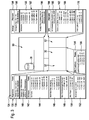
- the machine tool 10 For the machining of the workpiece by moving the NC axes X 2, Y 2, Z 2, X 3, Z 3, Z 4, the machine tool 10 is provided with a designated as a whole with 20 machines controller which an action controller 30 having a first data processing unit 32 which in turn is formed by a processor 34 and a memory 36, wherein the memory 36 is formed as a memory with fast access, that is, for example, as a RAM memory.
- a core control program designated as a whole by 38 which is capable of processing CNC sets of one or more part programs 40, for example from the part programs 40 1 to 40 4 , wherein the part programs 40 1 to 40 4 individual channels 42 1 to 42 4 of the core control program 38 are assigned, which allow the parallel processing of the individual part programs 40 1 to 40 4 , which is either independent of each other or can be synchronized by Synchronisierbetatione.
- control commands 44 1 to 44 4 are determined, which serve to initiate and control actions of the processing units 14.
- one of the channels 42 is assigned to an operation of one or more processing units 14, for example the axes of movement X 2 , Y 2 , Z 2 of the processing unit 14 2 , and a rotational speed or a rotational position of the processing unit 14 1 , about the spindle axis S.
- a drive control 45 with drive amplifier 46 1 to 46 4 and control circuits 47 1 , 47 2 , 47 3 and 47 4 is provided for each of the channels 42, the respective axle drives 48, for example, the axle drives 48 1 , 48 second , 48 3 and 48 4 , operate regulated, wherein the drive amplifier 46, the control circuits 47 and the axle 48 form a drive system 50 of the machine tool 10.
- the control circuits 47 may be, for example, position control circuits and / or speed control loops.
- a programmable controller 52 is additionally provided in the action control 30 in addition to the first data processing unit 32, which in turn has a processor 54 and a memory 56, as memory with fast access.
- programmable logic controller 52 are additional functions, such as the coolant supply 16 or the workpiece handling 18 controllable.
- an additional function control program 58 is provided, which has individual sub-functions 60 1 and 60 2 , which also serve to generate additional function control commands 64 1 and 64 2 , the corresponding Aktortheseen 66 1 and 66 2 are transmitted to corresponding actuators 68 1 and 68 second head for.
- the action controller 30 is controllable by an operator control 70, designated as a whole, having a data processing unit 72, which in turn includes, for example, a processor 74 and a memory 76 for one or more CNC machining program complexes 78.
- a whole designated 80 and in Fig. 2 schematically illustrated operating program which has a user interface 82 which cooperates with a designated as a whole by 90 machine control unit, also referred to as machine control panel, for example, includes a conventional keypad 92 and rows 94 and 96 of function keys 98 1 to 98 n .
- the machine control panel 90 is preferably associated with a display panel 100, which allows the display of information determined by the operating program 80.
- the display panel 100 can be controlled by the user interface 82.
- the operating program 80 communicates with the core control program 38 via a fitting program 84.
- the operating program 80 further includes, for example, an in Fig. 2 as a whole, the program management function designated 102 which is capable of workpiece-managing the CNC machining program complex 78 stored in the memory 76, that is, the program management function 102 manages the individual part programs 40 of the CNC machining program complex 78 to correspond to the respective one Workpiece WS belonging parts programs 40 processed according to their functional affiliation.
- the program management function 102 manages the individual part programs 40 of the CNC machining program complex 78 to correspond to the respective one Workpiece WS belonging parts programs 40 processed according to their functional affiliation.
- a transfer mode 104 of the program management function 102 provides that the parts programs 40 belonging to the same workpiece WS are transferred in their functional relationship from the operator control 70 to the action controller 30 and are handed over to the core control program 38, ie, for example individual channels 42 of the core control program 38 are assigned functionally correct and activated accordingly.
- a program processing function 112 and / or an analysis function 114 as well as a configuration function 116 and a tool function 118.
- a parameter field 130 is provided in a program environment 132 of the core control program 38, which, as in FIG Fig. 3 illustrated, core control parameters 134 included in Fig. 3 are shown by way of example.
- Such core control parameters 134 may be subdivided into general parameters 136, such as timing parameters, which are, for example, the timing of the interpolator and / or the duty cycle of the position controller.
- general parameters 136 may also include time parameters 140, which define, for example, a time of the auxiliary function output.
- the core control parameters 134 also include axis-specific parameters 142, which include, for example, gain parameters 144, which are parameters that define the loop gain of the individual control loops 47.
- the axis-specific parameters 142 include acceleration parameters 146, which define, for example, the maximum acceleration of the NC axes by the drive amplifiers 46.
- the axis-specific parameters 142 include speed parameters 148, which define, for example, maximum travel speeds or maximum rotational speeds of the respective axis.
- the axis-specific parameters 142 also include jerk parameters 150, which define, for example, the maximum jerk of a respective NC axis.
- axis-specific parameters 142 also include axle position parameters 152, which define the respective maximum axle positions.
- the parameter field 130 also includes, in addition to the core control parameters 134, CNC function parameters 154, which have, for example, look-ahead parameters 156 for the individual NC axes.
- a look-ahead view of the tool path is referred to as a look-ahead function, which reduces the feed to corners and edges in a timely and automatic manner to a permissible extent for the maximum permissible path deviation, this function being characterized by at least one preferably several look-ahead parameters 156, such as the feed rate and / or maximum path deviation, can be fixed.
- the additional function control program 58 is also assigned a parameter field 160, in which as a whole 162 additional function parameters are provided, with which the additional function control program 58 operates.
- the additional function parameters 162 comprise, for example, SPS parameters 164, which in turn have, for example, address parameters 166 for an input / output of information and / or numerical function parameters 168 or interrupt parameters 170.
- the additional function control program 58 can thus be adapted to the respective machine tool.
- the operating program 80 also comprises a parameter field 180 which has operating parameters 182 which serve to adapt the operating program 80 to the respective specific machine tool.
- operating parameters 182 include, for example, display parameters 184, which in turn have, for example, channel display parameters 186, axis name parameters 188 and coordinate system parameters 190.
- Both the core control parameters 134 and the additional function parameters 162 and the operating parameters 182 include type-specific, that is provided for the respective machine type parameters, as well as individual parameters, that is, on the individual machine tool, for example, identified by their serial number, related individual parameters, the Adjust control functions to the specific machine tool 10 that is specifically equipped.
- the general parameters 136 are typically type-specific configuration parameters, while the axis-specific parameters 142 as well as the CNC function parameters 154 are individual configuration parameters.
- the individuality in the axis-specific parameters 142 is due to the fact that, for a specific machine type, for example, a ball screw deviating from the standard equipment of the machine type has been installed in order to achieve higher feed forces, in which case the acceleration parameters 146 at least for this NC -Axis adjusted, eg chosen lower.
- the individuality in the axis-specific parameters 142 may also be due to processing units 14 deviating from the standard equipment of a machine type, which require an adaptation of the gain parameters 144 and / or the speed parameters 148.
- the CNC function parameters 154 may be selected differently from standard values of a machine type, depending on how accurate a user-specific manufacturing process is, so that the look-ahead parameters 156 are adapted according to the arithmetic operations to be performed.
- the additional function parameters 162 for example in the form of the address parameters 166 and the interrupt parameters 170, also include type-specific configuration parameters, while, for example, the numerical function parameters 168 represent individual configuration parameters.
- the workpiece handling is often individually tailored to the workpiece to be machined WS, whereby individual, for example, tuned function parameters 168 are necessary.
- the operating parameters 182 also include type-specific configuration parameters, namely, for example, the channel representation parameters 186 and the coordinate system parameters 190, while the axis designation parameters 188 represent individual configuration parameters.
- the axis designations are also individually adapted, so that in these cases the axis designation parameters 188 also deviate from a standard designation of a machine type.
- the operating control 70 is as in FIG Fig. 1 an external data storage device 192 is associated with a data carrier 198, in which a configuration parameter transfer mode 122 of the configuration function 116 of the operating program 80, a storage of all configuration parameters 134, 154, 162 and 182 is possible.
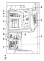
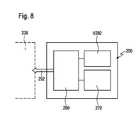
- FIG Fig. 4 A view of a real engine control unit 90 is shown in FIG Fig. 4 shown. This is arranged for example on a Maschinenverhaubung 196 of the machine tool.
- the machine control unit 90 is associated with an operator assistance system 200 which comprises a visualization unit 210 arranged on a housing 202 of the machine control unit 90 with a screen 212 which is displaceably mounted on guides 204 in a direction 206 and can be operated by means of operating elements 208, 209
- Control 208 is a keypad and control 209 is a mouse.
- the visualization unit 210 on the housing 202 of the machine control unit 90, it is possible to position it in an active position, which is shown in FIG Fig. 4 to position laterally adjacent to the housing 202 of the machine control unit 90, or to position the shift in the direction 206 in an inactive position not recognizable from the front and protected behind the housing 202, ie between this and the Maschinenverhaubung 196.
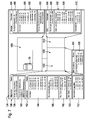
- FIG. 5 and 7 schematically illustrated operator support system 200 may be operated as a virtual machine tool, designated as a whole by V10, independently of the machine controller 20 and forms comprises a designated as a whole with V20 own machine control, which has an action control V30, the first data processing unit V32 with a processor V34 and a memory V36, wherein the memory V36 is formed as a memory with fast access.
- a core control program designated as a whole by V38 which in the simplest case is identical in design, as the core control program 38 of the real machine tool 10, but in any case is capable of, the CNC sets of one or more parts programs 40, for example, also from the part programs 40 1 to 40 4 to process in the same manner as the core control program 38, wherein the processing of the part programs 40 1 to 40 V42 1 to V42 4 takes place 4 in the same manner as the core control program 38 in individual channels of the core control program V38, so that a parallel execution of the individual part programs 40 1 to 40 4 is possible, which takes place either independently or synchronized by Synchronisierbetatione.
- control commands V44 1 to V44 4 are determined, which correspond in principle to the control commands of the real machine tool 10, but possibly run on a different time scale.
- the control commands V44 1 to V44 4 serve to cause virtual processing units V14 1 to V14 4 to act, wherein the virtual processing units V14 1 to V14 4 are displayed by a visualization unit 210, for example on a screen 212 of the visualization unit 210.
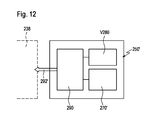
- the representation of the virtual processing units V14 relative to a virtual machine bed V12 by the visualization unit 210 takes place by means of a visualization controller 220, which has a further data processing unit 222, which in turn has a processor 234 and a memory 236 in which a visualization program 238 and a machine model 240 and a tool modeling system 250 are present.
- the visualization program 238 is embodied such that the individual processing units V14 of the real machine tool are represented on the visualization unit 210 by means of the geometry data of the machine model 240, preferably the three-dimensional geometry data of the machine model 240, of the machine tool data 242, if possible identical to the real one Machining units 14 of the real machine tool 10.
- the machine model 240 has stored the three-dimensional geometry data of all the machining units 14 and the machine bed 12 present in the real machine tool 10 and from this machine configuration data 242 are generated and transmitted to the visualization program 238.
- the geometry data are preferably read once when setting up the virtual machine tool V10 by the machine controller 20 or a memory device.
- the tool modeling system 250 is preferably designed such that it is capable of providing the visualization program 238 with tool configuration data 252 with which the visualization program 238 assigns the virtual tools VWZ to individual tool stations of the processing units V14.
- the visualization program 238 is able to display actions of the virtual processing units V14 on the visualization unit 210, in particular the screen 212 thereof, corresponding to the control commands V44, namely movements corresponding to the real NC axes X, Y, Z along the virtual NC Axes VX, VY, VZ.
- the visualization program 238 preferably operates such that virtual control commands V44, which are identical to real control commands 44, generate movements of the virtual processing units V14 corresponding to the virtual NC axes VX, VY, VZ, which correspond to the movements of the real processing units 14, taking into account a representation scale ,
- the action control V30 is still associated with a programmable logic controller V52, which in turn a processor V54 and a memory V56, designed in particular as a memory with fast Access, has.
- Additional functions can also be simulated with the programmable logic controller V52 in the same way as in the case of the real machine tool 10, such as, for example, the operation of a virtual coolant supply V16 or a virtual workpiece handling V18, both of which can also be displayed on the screen 212 of the visualization unit 210 in the same way as the processing units V14, namely by geometry data stored in the machine model 240.
- an additional function control program V58 is provided, which has individual subfunction programs V60, for example the subfunction programs V60 1 and V60 2 , which also serve to generate additional function control commands V64 1 and V64 2 , which are then transmitted to the visualization program 238.
- the action control V30 is further controllable by an operator control designated as a whole by V70, which has a data processing unit V72, which in turn for example comprises a processor V74 and a memory V76 for one or more CNC machining program complexes 78.
- the machining tool complexes 78 for the virtual machine tool V10 are constructed and designed in an identical manner as the real CNC machining program complexes 78 of the real machine tool 10 in order to have the possibility to test one and the same CNC machining program complex 78 on the one hand on the virtual machine tool V10 On the other hand, they can then be used unchanged on the real machine tool 10 for processing a real workpiece WS.
- the data processing unit V72 runs as a whole designated V80 and in Fig. 6 illustrated operating program, which has a user interface V82, which cooperates with a designated as a whole with V90 operator control unit, for example, a virtual, shown on the visualization unit 210 commonly designed keypad V92 and rows V94 and V96 of function keys V98 1 to V98 n , so that the operator control unit V90 is a virtual machine control panel in which, controlled by the user interface V82, keypads V92 and the Rows V94 and V96 of function keys V98 1 to V98 4 are shown on a screen V99 and are operable via the controls 208, 209 by means of a cursor, wherein the virtual machine control panel appears in a portion of the screen 212, while the other portion for displaying the virtual Processing of the virtual workpiece VWS is used.
- V90 operator control unit for example, a virtual, shown on the visualization unit 210 commonly designed keypad V92 and rows V94 and V96 of function keys V98 1 to V98 n ,
- the machine control panel V90 is preferably also associated with a display field V100 shown on the screen V99, which enables the display of information transmitted by the operating program V80.
- the display field V100 can be controlled by the user interface V82.
- the operating program V80 includes, for example, at least those also present in the real machine tool 10 and in Fig. 6 program management function as a whole designated V102 having a transfer mode V104 that operates identically to the real machine tool 10.
- the operating program V80 communicates with the core control program V38 via a fitting program V84.
- the operating program V80 can have all functionalities, as described for example in the German patent application DE 10 2005 045 028 A1 are described.
- the core control parameters 134 may be the same as the core control parameters used in the real machine tool 10.
- the kernel control parameters 134 include the type specific configuration parameters, such as the general parameters 136, as these are specific to the particular type of machine tool 10.
- all dynamically relevant configuration parameters are preferably also present in the parameter field V130, in particular the axis-specific parameters 142 and the CNC function parameters 154, since these are responsible for the speed of execution of the NC blocks in the simulation of a machining of a workpiece WS by processing a virtual workpiece VWS by means of the machining program complex 78 are essential.
- parameter field V130 of the virtual machine tool V10 all configuration parameters that are also present in the parameter field 130 of the real machine tool 10 are preferably included.
- the additional function control program V58 is also assigned a parameter field V160, which is suitable for receiving the additional function parameters designated 162.
- all type-specific additional function parameters 162 such as axis parameter 166 or interrupt parameter 170, are present in the parameter field V160.
- the additional functions are also to be taken into account and thus simulated in the simulation of the machining program complex 78, it is also necessary for the individual configuration parameters, such as axis designation parameters, to be present in the parameter field V160 in order to process the additional functions in the same manner in the case of the virtual machine tool V10 to be able to, as in the real machine tool 10.
- the operating program V80 is also provided with a parameter field V180, in which the operating parameters 182 can be stored, which are used to adapt the operating program V80 to the respective virtual machine tool V10.
- a configuration function V116 of the operating program V80 is equipped with a configuration parameter transfer mode V124 which is capable of outputting the individual configuration parameters 142, 154, 168, 188 assigned to the very specific real machine tool 10 from an external data storage device V192, for example before a first start of the simulation the data carrier 194 of the data storage device 192 read and write in the parameter fields 130, 160, 180 of the virtual machine tool V10.
- a virtual machine tool V10 that has been configured in a type-specific manner becomes a virtual machine tool V10 adapted to at least substantial configuration parameters of a single individual real machine tool 10.
- the configuration parameters present in the case of the real machine tool 10 can be simply transferred to the virtual machine tool V10.
- a data transmission connection for example a data line, between the operating control 70 and the operating control V70 is used.
- the configuration parameter transfer mode V124 writes all configuration parameters present in the memory device V192 into the parameter fields 130, 160, 180.
- the core control program V38 is a virtual
- Time step 260 associated with which comprises an Interpolatortaktgeber 262 for generating a virtual Interpolatortaktes VIT, and a time detection unit 264 for converting generated by the virtual Interpolatortakt virtual clock intervals in real-time intervals and thus conversion of the virtual time VT in a real time RT.
- the real time RT is output, for example, via the operating program V80 in the display field V100 of the operating program V80.
- the interpolator clock 262 of the virtual timer 260 is capable of generating a virtual interpolator clock VIT at which the clock intervals deviate from the clock intervals of the real interpolator clock IT, for example being significantly larger than the intervals of the real interpolator clock IT.
- the simulation based on the virtual interpolator clock VIT of the interpolator clock 262 can be carried out, for example, in a time-delayed manner in order to allow the operator to possible collisions or near-collisions to investigate exactly, in this investigation due to the virtual interpolator cycle and the individual adaptation of the machine model 240 as well as the adoption of the individual configuration parameters, the processing units V14 move substantially in each moment as relative to each other as in reality.
- the time recording stage 264 still provides the possibility of directly determining the real time RT directly from the virtual time VT, so that not only collisions of processing units V14 can be determined in the simulation of the processing of a virtual workpiece VWS by means of a CNC machining program complex also sentence run times for the execution of CNC sets or even times of the respective workpiece VWS, which correspond due to the conversion of the virtual time VT in a real time RT the block run times of processing a real workpiece WS on a real machine tool 10, so that the virtual Machine tool V10 already in the simulation of a CNC machining program complex 78 also allows statements about the set running times or piece times and thus also an optimization of the times.
- the tool modeling system 250 comprises tool data V280, which contains information about actual dimensions of the virtual tool VWZ, these actual dimensions of the virtual tool VWZ being essential for the machining of the virtual workpiece WS, and of the core control program V38 when processing the CNC sets are taken into account if the tool data V280 are stored together with the CNC machining program complex 78 in the memory provided for this purpose V76.
- the tool modeling system 250 also includes a tool configuration data generator 290, which configures the tool configuration data 292 from the tool model 270 and the tool data 292, which are transferred to the visualization program 238, so that in connection with the virtual machine tool V10 corresponding to the tool data V280 configured virtual tools VWZ in the individual tool positions of the virtual processing units V14 uses.
- a tool configuration data generator 290 which configures the tool configuration data 292 from the tool model 270 and the tool data 292, which are transferred to the visualization program 238, so that in connection with the virtual machine tool V10 corresponding to the tool data V280 configured virtual tools VWZ in the individual tool positions of the virtual processing units V14 uses.
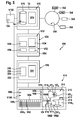
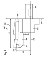
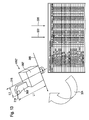
- Such a virtual tool VWZ is exemplary in Fig. 9 shown, which is a so-called three-dimensional geometry model.
- Such a virtual tool VWZ comprises a tool holder identified as a whole by 300 and identifiable by a tool identification number, which is formed from a tool holder body 302 which has, for example, a holding shank 304 with which the tool holder body 302 is fixed in a tool holder of a processing unit V14.
- the tool holder body 302 has a contact surface 306 with which it can be applied to a support surface of the processing unit V14, for example a tool turret or a different type of tool carrier.
- the holding element 304 and the tool holder body 302 are firmly connected to each other and form a coherent unit.
- a tool holding shank designated as a whole by 308 can be inserted into the tool holder body 302, wherein the tool holding shank 308 can be mounted in a receptacle 310 of the tool holder body 302 in various positions relative to the tool holder body 302.
- the tool holding shank 308 carries a cutting element 312, for example an insert whose cutting edge 314 is used for machining.
- a measure L1 which indicates the position of the cutting edge 314 over the abutment surface 306, and a length dimension L2, which indicates the position of the cutting edge 314 relative to an axis 316 that is perpendicular to the abutment surface 306 and centered by the retainer 304.
- Tool holder 300 shown in the tool model the three-dimensional geometry data of the tool holder body 302 with the contact surface 306, and the tool holding shaft 308 and the cutting plate 312 stored.
- the length measures L1 and L2 correspond to the tool data V280 and the tool configuration data generator 290 forms the tool configuration data 292 of the virtual tool VWZ from the three-dimensional geometry data of the tool holder body 302, the tool holding shaft 308, the insert 312 and the linear measures L1 and L2, which are then transferred to the visualization program 238 become.
- the operation control V180 is provided with a tool function V118, which in a tool data entry mode V322 provides the possibility to specify tool data V280 directly by data input to the tool modeling system 250 and then in a tool generation mode 324 with the tool configuration data generator 290 to generate the tool configuration data 292 in order to be able to display the virtual tool VWZ on the screen 212 of the visualization unit 210 by means of the visualization program 238.
- the tool data 280 stored in connection with the machining program complex 78 corresponds to the real tool data 280 when the operator has already set up the tools WZ on the real machine tool 10 and measured them at a measuring station, and these tool data 280 are then stored in the memory 76 corresponding to the CNC. Associated machining program complex 78.
- the real tool data 280 are also provided via an interface 282 between the operator control 70 of the machine tool 10 and the operator control V70 of the machining program complex 78 virtual machine tool V10 transferred to the memory V76.
- the tool data transfer mode V326 enables Transfer of the real tool data 280 from the memory V76 into the tool modeling system 250 so that the real tool data 280 is present in the latter and used to generate the tool configuration data 292. This means that the input of the tool data 280 into the tool modeling system 250 takes place by way of the data transfer of the real tool data 280 from the memory V76 and can be used directly to generate the tool configuration data 292.
- the tool function 118 first based on the three-dimensional geometry data of the tool model 270, the individual components of the tool holder 300, so for example, the tool holder body 302, the holding member 304, the tool holding shank 308 and the cutting plate 312 graphically, for example, on the display panel V100 of the machine control panel V90 represent and to position relative to each other, so that only by manual relative positioning of the tool holder body 302, the tool holding shaft 308 and the cutting plate 312, the virtual tool VWZ arises.
- the tool data V280 in the tool modeling system 250 can then also be transferred from the tool modeling system 250 to the memory V76 and assigned to the CNC machining program complex 78 with the tool data transfer mode V326, so that the core control program V38 also works on performing a simulation with the tool data V280 the tool modeling system 250 has been generated with the tool data generation mode 328, and thus also the control of the individual actions taking into account these virtual tool data V280 takes place.
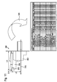
- the tool model 270 'does not include exact geometry data of the individual components for constructing a virtual tool VWZ, but geometric solids, from which individual solids can be selected and their dimensions can be entered by the operator.
- the tool configuration data generator 290 does not generate tool configuration data 292 substantially identical to the real tool, but tool configuration data 292 'which results in a virtual tool VWZ' which is exact in the tool data, particularly the lengths L1 and L2, of its tool holder body 302 'and its tool holding shaft 308', however, can deviate significantly from the actual real conditions ( Fig. 13 ).
- the tool data V280 can also be input in the same way in this embodiment, as shown in connection with the first embodiment.
- the simulation of the processing of the virtual workpiece VWS with the virtual processing units on the operator assistance system 200 according to the invention can be carried out with high significance with respect to the real processing of a real workpiece WS on the machine tool 10, the simulation is also suitable for the current operation Monitoring, for example, for the first time to be performed processing of a real workpiece.
- the operator support system 200 allows, for example, parallel to the machining of a real workpiece WS on the real machine tool 10 in the operator support system 200 on the virtual machine V10 perform a simulation of the same machining program complex 78, that is, a simulation of processing the same virtual workpiece VWZ with the virtual processing units V14, wherein with the visualization program 238 a collision detection program 340 is linked, the collisions of the virtual processing units V14 with each other and / or recognizes the machine bed V12, in which case the visualization program 238 outputs a stop command 342, which acts directly on the drive system 50 and the real machine tool 10 stops as soon as possible.
- the checking of the actions of the virtual processing units V14 takes place with the necessary advance in relation to the actions of the real processing units 14 of the machine tool 10, then it can be ensured that the stop signal 342 in the collision of virtual processing units V14 with each other or with the machine bed V12 before the actual collision the real processing units 14 are issued with each other and / or with the machine bed 12 and leads to a stop of the real machine tool 10 before the real real collision.
- the operator assistance system 200 which operates completely separately and independently of the machine control 20, is coupled to the data processing unit V72 assigned to the operating control V70 with an internal data network 350 which gives the operator of the machine tool 10 the possibility to obtain additional information directly at the machine tool 10 from the in-house data network 350, which may be relevant to the execution of a particular job for machining workpieces WS.
- the in-house data network 350 is designed to provide the ability to obtain workpiece information 352, such as that found in a CAM system.
- This workpiece information 352 may be essential for machining the workpiece WS on the real machine tool, for example, in machining problems.
- a user of the machine tool 10 now has the option of obtaining the workpiece information of the CAM system from the operator support system 200 and displaying it on the visualization unit 210, either in the display field V100 or in the area of the screen 212, in which the virtual processing units V14 are usually located the virtual machine tool V10 are displayed.
- the operator can study workpiece information 352 on the machine tool 10 while, for example, the machine tool 10 processes workpieces WS controlled by the machine controller 20.
- the workpiece information 352 may also be relevant if problems occur during the first processing of the workpiece WS on the machine tool 10, be it problems with respect to the material or the dimensional accuracy of the workpiece during machining.
- design information 354 directly on the machine tool 10, for example design information 354 of a CAD system, which is likewise accessible via the company-internal data network 350 and likewise in the same way as the workpiece information 352 either in the display field V100 or in a region of the screen 212 intended for displaying the virtual processing units V14.
- the operator support system 200 is coupled to the machine controller 20 via a real-time interface 360 which provides data transfer between the core control program 38 of the machine control 20 and the core control program V38 of the operator assistance system 200, data of partially processed CNC sets in the individual channels 42 to the individual channels V42, so that the operator support system 200 does not perform a simulation of the machining of a virtual workpiece independent of the machine controller 20, but a simulation of the machining a virtual workpiece VWS, which is parallel to the processing of the real workpiece WS, the simulation works with partially calculated by the action control 30 in the individual channels 42 CNC sets, with the real-time interface 360, the partially machined CNC sets of the Channels 42 are passed directly to the channels V42 and processed in the channels V42 to virtual control commands V44.
- the control commands V44 are used to control the movement of the virtual processing units V14 as described above in connection with the simulation.
- the visualization program 238 is still provided with the collision monitoring program 340, which automatically monitors collisions of the processing units V14 with each other or else with the machine bed V12.
- this collision monitoring program 340 it is possible to automatically detect collisions and, upon detection thereof, output a stop signal 342 by the visualization program 238, which directly influences the machine control 20 of the real machine tool 10, the drive system 50 thereof and immediately brings the real machine tool 10 to a standstill.
- collision monitoring by the operator assistance system 200 is meaningful and efficient only if the collision detection program 340 detects the possible collision in good time prior to the actual collision on the real machine tool 10 that the real machine tool 10 can be stopped in time.
- the channels V42 operate in the so-called override mode, in which the entire machine operation, in particular the accelerations and travel speeds are higher than in the channels 42 of the machine control 20.
- the virtual override is more than 100%, better more than 500%, even better more than 1000%, and advantageously more than 2000%, so that the complete execution of the CNC sets in channels V42 is done as if the speeds are greater by a factor of more than 1, more than 5, more than 10, more than 20 and, for example, on the order of about 40 than is the case with the machine controller 20 of the real machine tool 10.
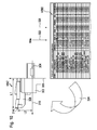
- Fig. 15 represented in the respective channel 42 of the respective CNC set the decoder 362 and the interpreter 364 passed a so-called lead 366, in which precalculated CNC sets created and stored in a memory 368 sequentially before a final execution of the CNC sets in the main run 370 takes place and finally the control commands 44 are output.
- the operator assistance system 200 receives precalculated CNC blocks from the machine control 20 in the lead 366 does not require activation of the operator support system 200 and thus timely start of the simulation of the machining of a virtual workpiece, since the workpiece WS is only currently being processed on the Level of channels 42 and V42 precomputed CNC sets are passed, which then automatically trigger in the operator support system 200, the determination of the control commands V44 with advance and thereby ensure the collision check with the respective lead.
- the fact that the CNC sets are pre-calculated in the lead 366 of the respective channel 42 allows to ensure that, compared to the first embodiment, the computation times in the operator support system 200, in particular in the channel V42 of the operator support system 200, have little effect on the execution have the CNC sets in the channel V42, since in this only the less processing power-requiring main run V370 is to be performed, and consequently the required lead due to lower processor power in the operator support system 200 can be maintained in the rule.
Landscapes
- Engineering & Computer Science (AREA)
- Human Computer Interaction (AREA)
- Manufacturing & Machinery (AREA)
- Physics & Mathematics (AREA)
- General Physics & Mathematics (AREA)
- Automation & Control Theory (AREA)
- Numerical Control (AREA)
Priority Applications (1)
| Application Number | Priority Date | Filing Date | Title |
|---|---|---|---|
| PL13171097T PL2650741T3 (pl) | 2007-09-14 | 2008-09-09 | Obrabiarka |
Applications Claiming Priority (4)
| Application Number | Priority Date | Filing Date | Title |
|---|---|---|---|
| DE102007045594 | 2007-09-14 | ||
| DE102007045620A DE102007045620A1 (de) | 2007-09-14 | 2007-09-17 | Werkzeugmaschine |
| EP08803919.3A EP2188682B1 (fr) | 2007-09-14 | 2008-09-09 | Machine-outil |
| PCT/EP2008/061951 WO2009037154A2 (fr) | 2007-09-14 | 2008-09-09 | Machine-outil |
Related Parent Applications (3)
| Application Number | Title | Priority Date | Filing Date |
|---|---|---|---|
| EP08803919.3 Division | 2008-09-09 | ||
| EP08803919.3A Division EP2188682B1 (fr) | 2007-09-14 | 2008-09-09 | Machine-outil |
| EP08803919.3A Division-Into EP2188682B1 (fr) | 2007-09-14 | 2008-09-09 | Machine-outil |
Publications (3)
| Publication Number | Publication Date |
|---|---|
| EP2650741A2 true EP2650741A2 (fr) | 2013-10-16 |
| EP2650741A3 EP2650741A3 (fr) | 2014-08-13 |
| EP2650741B1 EP2650741B1 (fr) | 2020-11-11 |
Family
ID=40435201
Family Applications (2)
| Application Number | Title | Priority Date | Filing Date |
|---|---|---|---|
| EP08803919.3A Active EP2188682B1 (fr) | 2007-09-14 | 2008-09-09 | Machine-outil |
| EP13171097.2A Active EP2650741B1 (fr) | 2007-09-14 | 2008-09-09 | Machine-outil |
Family Applications Before (1)
| Application Number | Title | Priority Date | Filing Date |
|---|---|---|---|
| EP08803919.3A Active EP2188682B1 (fr) | 2007-09-14 | 2008-09-09 | Machine-outil |
Country Status (4)
| Country | Link |
|---|---|
| EP (2) | EP2188682B1 (fr) |
| DE (1) | DE102007045620A1 (fr) |
| PL (1) | PL2650741T3 (fr) |
| WO (1) | WO2009037154A2 (fr) |
Cited By (1)
| Publication number | Priority date | Publication date | Assignee | Title |
|---|---|---|---|---|
| EP4339724A1 (fr) * | 2022-09-13 | 2024-03-20 | CHIRON Group SE | Système et procédé de simulation de déroulement de programme proche de la machine dans des machines-outils |
Families Citing this family (8)
| Publication number | Priority date | Publication date | Assignee | Title |
|---|---|---|---|---|
| DE102009023648A1 (de) | 2009-05-26 | 2010-12-02 | Index-Werke Gmbh & Co. Kg Hahn & Tessky | Steuerungssystem |
| WO2011147048A1 (fr) * | 2010-05-25 | 2011-12-01 | Liu Wenxiang | Commande numérique de réseaux |
| DE102010046274A1 (de) * | 2010-09-22 | 2012-03-22 | Netstal-Maschinen Ag | Verfahren zur Überprüfung eines hinterlegten Produktionsablaufes für eine oder mehrere Maschinen mit einem zyklischen Maschinenbetriebsablauf |
| DE202011000315U1 (de) | 2011-02-11 | 2012-05-21 | Kuka Systems Gmbh | Falzwerkzeug |
| JP6077601B2 (ja) | 2014-08-22 | 2017-02-08 | ファナック株式会社 | 加工プログラムのサイクルタイムを短縮する数値制御装置 |
| CN106886196A (zh) * | 2015-12-16 | 2017-06-23 | 上海睿锆信息科技有限公司 | 与数控系统直接通讯的计算机辅助制造方法及装置和系统 |
| CN114245884B (zh) * | 2019-07-26 | 2024-10-29 | 赫克斯冈技术中心 | 用于计算机数控加工刀具的优化 |
| EP3889708A1 (fr) * | 2020-03-31 | 2021-10-06 | Siemens Aktiengesellschaft | Optimisation des processus d'usinage par enlèvement de copeaux sur les machine-outils |
Citations (1)
| Publication number | Priority date | Publication date | Assignee | Title |
|---|---|---|---|---|
| DE102005045028A1 (de) | 2005-09-12 | 2007-03-22 | Index-Werke Gmbh & Co. Kg Hahn & Tessky | Simulationssystem |
Family Cites Families (8)
| Publication number | Priority date | Publication date | Assignee | Title |
|---|---|---|---|---|
| JPS58203512A (ja) * | 1982-05-21 | 1983-11-28 | Mitsubishi Electric Corp | 数値制御装置 |
| DE19739559A1 (de) * | 1997-09-09 | 1999-03-18 | Traub Drehmaschinen Gmbh I L | Verfahren und System zum Erstellen oder Visualisieren von Steuerdatensätzen |
| US6101425A (en) * | 1997-11-26 | 2000-08-08 | Allen-Bradley Company, Llc | Multiple connection networked man-machine interfaces for computer numerical controls |
| DE10114811A1 (de) * | 2001-03-26 | 2002-10-10 | Volkswagen Ag | System und Verfahren zur Erstellung von mehrachsigen Bearbeitungs-Vorgängen an Werkstücken |
| DE10257229A1 (de) * | 2002-12-07 | 2004-06-24 | P&L Gmbh & Co. Kg | Vorrichtung zur Steuerung einer Werkzeugmaschine sowie Werkzeugmaschinen mit einer solchen Vorrichtung |
| DE10347169A1 (de) * | 2003-10-07 | 2005-05-12 | Traub Drehmaschinen Gmbh | Verfahren zur Steuerung einer Werkzeugmaschine und Werkzeugmaschinensteuerung |
| DE10352815B4 (de) * | 2003-11-12 | 2009-06-25 | Siemens Ag | Simulationsverfahren für eine Bearbeitung eines Werkstücks durch eine Werkzeugmaschine und korrespondierender Rechner |
| EP1818763A1 (fr) * | 2006-02-08 | 2007-08-15 | Hurco Companies Inc. | Simulateur de contrôle d'un ordinateur portable |
-
2007
- 2007-09-17 DE DE102007045620A patent/DE102007045620A1/de not_active Ceased
-
2008
- 2008-09-09 EP EP08803919.3A patent/EP2188682B1/fr active Active
- 2008-09-09 PL PL13171097T patent/PL2650741T3/pl unknown
- 2008-09-09 WO PCT/EP2008/061951 patent/WO2009037154A2/fr not_active Ceased
- 2008-09-09 EP EP13171097.2A patent/EP2650741B1/fr active Active
Patent Citations (1)
| Publication number | Priority date | Publication date | Assignee | Title |
|---|---|---|---|---|
| DE102005045028A1 (de) | 2005-09-12 | 2007-03-22 | Index-Werke Gmbh & Co. Kg Hahn & Tessky | Simulationssystem |
Cited By (1)
| Publication number | Priority date | Publication date | Assignee | Title |
|---|---|---|---|---|
| EP4339724A1 (fr) * | 2022-09-13 | 2024-03-20 | CHIRON Group SE | Système et procédé de simulation de déroulement de programme proche de la machine dans des machines-outils |
Also Published As
| Publication number | Publication date |
|---|---|
| WO2009037154A3 (fr) | 2009-06-11 |
| PL2650741T3 (pl) | 2021-05-04 |
| EP2650741A3 (fr) | 2014-08-13 |
| DE102007045620A1 (de) | 2009-04-16 |
| EP2188682B1 (fr) | 2014-12-24 |
| WO2009037154A2 (fr) | 2009-03-26 |
| EP2188682A2 (fr) | 2010-05-26 |
| EP2650741B1 (fr) | 2020-11-11 |
Similar Documents
| Publication | Publication Date | Title |
|---|---|---|
| EP2188684B1 (fr) | Machine-outil virtuelle servant à représenter des actions menées par des unités d'usinage d'une machine-outil réelle | |
| EP2188682B1 (fr) | Machine-outil | |
| DE102007045595A1 (de) | Verfahren und virtuelle Werkzeugmaschine zur Darstellung von Aktionen einer realen Werkzeugmaschine | |
| DE102010036499B4 (de) | Werkzeugvektor-Anzeigevorrichtung für eine Werkzeugmaschine mit Drehachse | |
| EP1901149B1 (fr) | Procédé et dispositif destinés à la simulation de l'usinage d'une pièce sur une machine-outil | |
| DE102010017763B4 (de) | Gerät zum Anzeigen des Werkzeugwegs für Werkzeugmaschinen | |
| DE3707579C2 (fr) | ||
| DE102011108282B4 (de) | Numerische Steuerung für eine Mehrachsenmaschine zum Bearbeiten einer geneigten Bearbeitungsebene | |
| DE102018218298B4 (de) | Bearbeitungssystem | |
| DE112017000203B4 (de) | Numerische Steuerung und numerisches Steuerungsverfahren | |
| EP1762919B1 (fr) | Système de simulation | |
| DE10352815B4 (de) | Simulationsverfahren für eine Bearbeitung eines Werkstücks durch eine Werkzeugmaschine und korrespondierender Rechner | |
| DE3545795C2 (de) | Vorrichtung zur numerischen Steuerung | |
| DE102009004285A1 (de) | Verfahren und Vorrichtung zur Optimierung, Überwachung oder Analyse eines Prozesses | |
| DE102005027947A1 (de) | Vorrichtung zum Überprüfen einer Störung | |
| DE112009004603T5 (de) | Numerische Steuervorrichtung und Verfahren zum Steuern dernumerischen Steuervorrichtung | |
| EP1018677A1 (fr) | Système virtuel d'apprentissage | |
| DE102020124734A1 (de) | Simulationsgerät | |
| EP2837981B1 (fr) | Procédé et dispositif de configuration automatisée d'une fonction de surveillance d'un robot industriel | |
| DE102017009760A1 (de) | Numerische Steuervorrichtung und Steuerverfahren für eine numerische Steuervorrichtung | |
| DE112009004583B4 (de) | Numerische Steuervorrichtung, Verfahren zum Steuern derselben und Systemprogramm dafür | |
| DE102004019653B4 (de) | Simulationsvorrichtung | |
| DE68929105T2 (de) | Instruktionssystem für numerische daten | |
| EP3582043B1 (fr) | Procédé, dispositif de commande numérique ainsi que machine-outil destiné à l'usinage d'une pièce à usiner | |
| DE102007017048A1 (de) | Vorrichtung und Verfahren zur Kontrolle eines Werkzeugs |
Legal Events
| Date | Code | Title | Description |
|---|---|---|---|
| PUAI | Public reference made under article 153(3) epc to a published international application that has entered the european phase |
Free format text: ORIGINAL CODE: 0009012 |
|
| AC | Divisional application: reference to earlier application |
Ref document number: 2188682 Country of ref document: EP Kind code of ref document: P |
|
| AK | Designated contracting states |
Kind code of ref document: A2 Designated state(s): AT BE BG CH CY CZ DE DK EE ES FI FR GB GR HR HU IE IS IT LI LT LU LV MC MT NL NO PL PT RO SE SI SK TR |
|
| PUAL | Search report despatched |
Free format text: ORIGINAL CODE: 0009013 |
|
| AK | Designated contracting states |
Kind code of ref document: A3 Designated state(s): AT BE BG CH CY CZ DE DK EE ES FI FR GB GR HR HU IE IS IT LI LT LU LV MC MT NL NO PL PT RO SE SI SK TR |
|
| RIC1 | Information provided on ipc code assigned before grant |
Ipc: G05B 19/409 20060101AFI20140710BHEP |
|
| 17P | Request for examination filed |
Effective date: 20150211 |
|
| RBV | Designated contracting states (corrected) |
Designated state(s): AT BE BG CH CY CZ DE DK EE ES FI FR GB GR HR HU IE IS IT LI LT LU LV MC MT NL NO PL PT RO SE SI SK TR |
|
| STAA | Information on the status of an ep patent application or granted ep patent |
Free format text: STATUS: EXAMINATION IS IN PROGRESS |
|
| 17Q | First examination report despatched |
Effective date: 20190410 |
|
| GRAP | Despatch of communication of intention to grant a patent |
Free format text: ORIGINAL CODE: EPIDOSNIGR1 |
|
| STAA | Information on the status of an ep patent application or granted ep patent |
Free format text: STATUS: GRANT OF PATENT IS INTENDED |
|
| INTG | Intention to grant announced |
Effective date: 20191121 |
|
| GRAJ | Information related to disapproval of communication of intention to grant by the applicant or resumption of examination proceedings by the epo deleted |
Free format text: ORIGINAL CODE: EPIDOSDIGR1 |
|
| STAA | Information on the status of an ep patent application or granted ep patent |
Free format text: STATUS: EXAMINATION IS IN PROGRESS |
|
| INTC | Intention to grant announced (deleted) | ||
| GRAP | Despatch of communication of intention to grant a patent |
Free format text: ORIGINAL CODE: EPIDOSNIGR1 |
|
| STAA | Information on the status of an ep patent application or granted ep patent |
Free format text: STATUS: GRANT OF PATENT IS INTENDED |
|
| INTG | Intention to grant announced |
Effective date: 20200528 |
|
| GRAS | Grant fee paid |
Free format text: ORIGINAL CODE: EPIDOSNIGR3 |
|
| GRAA | (expected) grant |
Free format text: ORIGINAL CODE: 0009210 |
|
| STAA | Information on the status of an ep patent application or granted ep patent |
Free format text: STATUS: THE PATENT HAS BEEN GRANTED |
|
| AC | Divisional application: reference to earlier application |
Ref document number: 2188682 Country of ref document: EP Kind code of ref document: P |
|
| AK | Designated contracting states |
Kind code of ref document: B1 Designated state(s): AT BE BG CH CY CZ DE DK EE ES FI FR GB GR HR HU IE IS IT LI LT LU LV MC MT NL NO PL PT RO SE SI SK TR |
|
| REG | Reference to a national code |
Ref country code: GB Ref legal event code: FG4D Free format text: NOT ENGLISH |
|
| REG | Reference to a national code |
Ref country code: CH Ref legal event code: NV Representative=s name: KIRKER AND CIE S.A., CH Ref country code: CH Ref legal event code: EP |
|
| REG | Reference to a national code |
Ref country code: AT Ref legal event code: REF Ref document number: 1334093 Country of ref document: AT Kind code of ref document: T Effective date: 20201115 |
|
| REG | Reference to a national code |
Ref country code: DE Ref legal event code: R096 Ref document number: 502008017162 Country of ref document: DE |
|
| REG | Reference to a national code |
Ref country code: IE Ref legal event code: FG4D Free format text: LANGUAGE OF EP DOCUMENT: GERMAN |
|
| REG | Reference to a national code |
Ref country code: NL Ref legal event code: FP |
|
| PG25 | Lapsed in a contracting state [announced via postgrant information from national office to epo] |
Ref country code: GR Free format text: LAPSE BECAUSE OF FAILURE TO SUBMIT A TRANSLATION OF THE DESCRIPTION OR TO PAY THE FEE WITHIN THE PRESCRIBED TIME-LIMIT Effective date: 20210212 Ref country code: PT Free format text: LAPSE BECAUSE OF FAILURE TO SUBMIT A TRANSLATION OF THE DESCRIPTION OR TO PAY THE FEE WITHIN THE PRESCRIBED TIME-LIMIT Effective date: 20210311 Ref country code: NO Free format text: LAPSE BECAUSE OF FAILURE TO SUBMIT A TRANSLATION OF THE DESCRIPTION OR TO PAY THE FEE WITHIN THE PRESCRIBED TIME-LIMIT Effective date: 20210211 Ref country code: FI Free format text: LAPSE BECAUSE OF FAILURE TO SUBMIT A TRANSLATION OF THE DESCRIPTION OR TO PAY THE FEE WITHIN THE PRESCRIBED TIME-LIMIT Effective date: 20201111 |
|
| PG25 | Lapsed in a contracting state [announced via postgrant information from national office to epo] |
Ref country code: IS Free format text: LAPSE BECAUSE OF FAILURE TO SUBMIT A TRANSLATION OF THE DESCRIPTION OR TO PAY THE FEE WITHIN THE PRESCRIBED TIME-LIMIT Effective date: 20210311 Ref country code: LV Free format text: LAPSE BECAUSE OF FAILURE TO SUBMIT A TRANSLATION OF THE DESCRIPTION OR TO PAY THE FEE WITHIN THE PRESCRIBED TIME-LIMIT Effective date: 20201111 Ref country code: SE Free format text: LAPSE BECAUSE OF FAILURE TO SUBMIT A TRANSLATION OF THE DESCRIPTION OR TO PAY THE FEE WITHIN THE PRESCRIBED TIME-LIMIT Effective date: 20201111 Ref country code: BG Free format text: LAPSE BECAUSE OF FAILURE TO SUBMIT A TRANSLATION OF THE DESCRIPTION OR TO PAY THE FEE WITHIN THE PRESCRIBED TIME-LIMIT Effective date: 20210211 |
|
| REG | Reference to a national code |
Ref country code: LT Ref legal event code: MG9D |
|
| PG25 | Lapsed in a contracting state [announced via postgrant information from national office to epo] |
Ref country code: HR Free format text: LAPSE BECAUSE OF FAILURE TO SUBMIT A TRANSLATION OF THE DESCRIPTION OR TO PAY THE FEE WITHIN THE PRESCRIBED TIME-LIMIT Effective date: 20201111 |
|
| PG25 | Lapsed in a contracting state [announced via postgrant information from national office to epo] |
Ref country code: LT Free format text: LAPSE BECAUSE OF FAILURE TO SUBMIT A TRANSLATION OF THE DESCRIPTION OR TO PAY THE FEE WITHIN THE PRESCRIBED TIME-LIMIT Effective date: 20201111 Ref country code: SK Free format text: LAPSE BECAUSE OF FAILURE TO SUBMIT A TRANSLATION OF THE DESCRIPTION OR TO PAY THE FEE WITHIN THE PRESCRIBED TIME-LIMIT Effective date: 20201111 Ref country code: RO Free format text: LAPSE BECAUSE OF FAILURE TO SUBMIT A TRANSLATION OF THE DESCRIPTION OR TO PAY THE FEE WITHIN THE PRESCRIBED TIME-LIMIT Effective date: 20201111 Ref country code: EE Free format text: LAPSE BECAUSE OF FAILURE TO SUBMIT A TRANSLATION OF THE DESCRIPTION OR TO PAY THE FEE WITHIN THE PRESCRIBED TIME-LIMIT Effective date: 20201111 Ref country code: CZ Free format text: LAPSE BECAUSE OF FAILURE TO SUBMIT A TRANSLATION OF THE DESCRIPTION OR TO PAY THE FEE WITHIN THE PRESCRIBED TIME-LIMIT Effective date: 20201111 |
|
| REG | Reference to a national code |
Ref country code: DE Ref legal event code: R097 Ref document number: 502008017162 Country of ref document: DE |
|
| PG25 | Lapsed in a contracting state [announced via postgrant information from national office to epo] |
Ref country code: DK Free format text: LAPSE BECAUSE OF FAILURE TO SUBMIT A TRANSLATION OF THE DESCRIPTION OR TO PAY THE FEE WITHIN THE PRESCRIBED TIME-LIMIT Effective date: 20201111 |
|
| PLBE | No opposition filed within time limit |
Free format text: ORIGINAL CODE: 0009261 |
|
| STAA | Information on the status of an ep patent application or granted ep patent |
Free format text: STATUS: NO OPPOSITION FILED WITHIN TIME LIMIT |
|
| 26N | No opposition filed |
Effective date: 20210812 |
|
| PG25 | Lapsed in a contracting state [announced via postgrant information from national office to epo] |
Ref country code: ES Free format text: LAPSE BECAUSE OF FAILURE TO SUBMIT A TRANSLATION OF THE DESCRIPTION OR TO PAY THE FEE WITHIN THE PRESCRIBED TIME-LIMIT Effective date: 20201111 Ref country code: SI Free format text: LAPSE BECAUSE OF FAILURE TO SUBMIT A TRANSLATION OF THE DESCRIPTION OR TO PAY THE FEE WITHIN THE PRESCRIBED TIME-LIMIT Effective date: 20201111 |
|
| REG | Reference to a national code |
Ref country code: BE Ref legal event code: MM Effective date: 20210930 |
|
| PG25 | Lapsed in a contracting state [announced via postgrant information from national office to epo] |
Ref country code: IS Free format text: LAPSE BECAUSE OF FAILURE TO SUBMIT A TRANSLATION OF THE DESCRIPTION OR TO PAY THE FEE WITHIN THE PRESCRIBED TIME-LIMIT Effective date: 20210311 Ref country code: MC Free format text: LAPSE BECAUSE OF FAILURE TO SUBMIT A TRANSLATION OF THE DESCRIPTION OR TO PAY THE FEE WITHIN THE PRESCRIBED TIME-LIMIT Effective date: 20201111 |
|
| PG25 | Lapsed in a contracting state [announced via postgrant information from national office to epo] |
Ref country code: LU Free format text: LAPSE BECAUSE OF NON-PAYMENT OF DUE FEES Effective date: 20210909 Ref country code: IE Free format text: LAPSE BECAUSE OF NON-PAYMENT OF DUE FEES Effective date: 20210909 Ref country code: BE Free format text: LAPSE BECAUSE OF NON-PAYMENT OF DUE FEES Effective date: 20210930 |
|
| PGFP | Annual fee paid to national office [announced via postgrant information from national office to epo] |
Ref country code: NL Payment date: 20220927 Year of fee payment: 15 Ref country code: GB Payment date: 20220922 Year of fee payment: 15 |
|
| PGFP | Annual fee paid to national office [announced via postgrant information from national office to epo] |
Ref country code: PL Payment date: 20220830 Year of fee payment: 15 |
|
| PG25 | Lapsed in a contracting state [announced via postgrant information from national office to epo] |
Ref country code: HU Free format text: LAPSE BECAUSE OF FAILURE TO SUBMIT A TRANSLATION OF THE DESCRIPTION OR TO PAY THE FEE WITHIN THE PRESCRIBED TIME-LIMIT; INVALID AB INITIO Effective date: 20080909 Ref country code: CY Free format text: LAPSE BECAUSE OF FAILURE TO SUBMIT A TRANSLATION OF THE DESCRIPTION OR TO PAY THE FEE WITHIN THE PRESCRIBED TIME-LIMIT Effective date: 20201111 |
|
| P01 | Opt-out of the competence of the unified patent court (upc) registered |
Effective date: 20230517 |
|
| REG | Reference to a national code |
Ref country code: NL Ref legal event code: MM Effective date: 20231001 |
|
| GBPC | Gb: european patent ceased through non-payment of renewal fee |
Effective date: 20230909 |
|
| PG25 | Lapsed in a contracting state [announced via postgrant information from national office to epo] |
Ref country code: NL Free format text: LAPSE BECAUSE OF NON-PAYMENT OF DUE FEES Effective date: 20231001 |
|
| PG25 | Lapsed in a contracting state [announced via postgrant information from national office to epo] |
Ref country code: TR Free format text: LAPSE BECAUSE OF FAILURE TO SUBMIT A TRANSLATION OF THE DESCRIPTION OR TO PAY THE FEE WITHIN THE PRESCRIBED TIME-LIMIT Effective date: 20201111 Ref country code: NL Free format text: LAPSE BECAUSE OF NON-PAYMENT OF DUE FEES Effective date: 20231001 |
|
| PG25 | Lapsed in a contracting state [announced via postgrant information from national office to epo] |
Ref country code: GB Free format text: LAPSE BECAUSE OF NON-PAYMENT OF DUE FEES Effective date: 20230909 |
|
| PG25 | Lapsed in a contracting state [announced via postgrant information from national office to epo] |
Ref country code: GB Free format text: LAPSE BECAUSE OF NON-PAYMENT OF DUE FEES Effective date: 20230909 |
|
| PG25 | Lapsed in a contracting state [announced via postgrant information from national office to epo] |
Ref country code: MT Free format text: LAPSE BECAUSE OF FAILURE TO SUBMIT A TRANSLATION OF THE DESCRIPTION OR TO PAY THE FEE WITHIN THE PRESCRIBED TIME-LIMIT Effective date: 20201111 |
|
| PG25 | Lapsed in a contracting state [announced via postgrant information from national office to epo] |
Ref country code: PL Free format text: LAPSE BECAUSE OF NON-PAYMENT OF DUE FEES Effective date: 20230909 |
|
| PG25 | Lapsed in a contracting state [announced via postgrant information from national office to epo] |
Ref country code: PL Free format text: LAPSE BECAUSE OF NON-PAYMENT OF DUE FEES Effective date: 20230909 |
|
| REG | Reference to a national code |
Ref country code: CH Ref legal event code: U11 Free format text: ST27 STATUS EVENT CODE: U-0-0-U10-U11 (AS PROVIDED BY THE NATIONAL OFFICE) Effective date: 20251001 |
|
| PGFP | Annual fee paid to national office [announced via postgrant information from national office to epo] |
Ref country code: DE Payment date: 20250919 Year of fee payment: 18 |
|
| PGFP | Annual fee paid to national office [announced via postgrant information from national office to epo] |
Ref country code: IT Payment date: 20250922 Year of fee payment: 18 |
|
| PGFP | Annual fee paid to national office [announced via postgrant information from national office to epo] |
Ref country code: FR Payment date: 20250908 Year of fee payment: 18 Ref country code: AT Payment date: 20250909 Year of fee payment: 18 |
|
| PGFP | Annual fee paid to national office [announced via postgrant information from national office to epo] |
Ref country code: CH Payment date: 20251001 Year of fee payment: 18 |