EP2660559B1 - Apparatus and method for measuring the bending angle of a sheet - Google Patents
Apparatus and method for measuring the bending angle of a sheet Download PDFInfo
- Publication number
- EP2660559B1 EP2660559B1 EP13166167.0A EP13166167A EP2660559B1 EP 2660559 B1 EP2660559 B1 EP 2660559B1 EP 13166167 A EP13166167 A EP 13166167A EP 2660559 B1 EP2660559 B1 EP 2660559B1
- Authority
- EP
- European Patent Office
- Prior art keywords
- sheet
- bending angle
- bending
- light pattern
- angle value
- Prior art date
- Legal status (The legal status is an assumption and is not a legal conclusion. Google has not performed a legal analysis and makes no representation as to the accuracy of the status listed.)
- Active
Links
Images




Classifications
-
- B—PERFORMING OPERATIONS; TRANSPORTING
- B21—MECHANICAL METAL-WORKING WITHOUT ESSENTIALLY REMOVING MATERIAL; PUNCHING METAL
- B21D—WORKING OR PROCESSING OF SHEET METAL OR METAL TUBES, RODS OR PROFILES WITHOUT ESSENTIALLY REMOVING MATERIAL; PUNCHING METAL
- B21D5/00—Bending sheet metal along straight lines, e.g. to form simple curves
- B21D5/006—Bending sheet metal along straight lines, e.g. to form simple curves combined with measuring of bends
-
- G—PHYSICS
- G01—MEASURING; TESTING
- G01B—MEASURING LENGTH, THICKNESS OR SIMILAR LINEAR DIMENSIONS; MEASURING ANGLES; MEASURING AREAS; MEASURING IRREGULARITIES OF SURFACES OR CONTOURS
- G01B11/00—Measuring arrangements characterised by the use of optical techniques
- G01B11/26—Measuring arrangements characterised by the use of optical techniques for measuring angles or tapers; for testing the alignment of axes
-
- B—PERFORMING OPERATIONS; TRANSPORTING
- B21—MECHANICAL METAL-WORKING WITHOUT ESSENTIALLY REMOVING MATERIAL; PUNCHING METAL
- B21D—WORKING OR PROCESSING OF SHEET METAL OR METAL TUBES, RODS OR PROFILES WITHOUT ESSENTIALLY REMOVING MATERIAL; PUNCHING METAL
- B21D5/00—Bending sheet metal along straight lines, e.g. to form simple curves
- B21D5/02—Bending sheet metal along straight lines, e.g. to form simple curves on press brakes without making use of clamping means
Definitions
- the present invention concerns an apparatus and method for measuring a bending angle of a sheet.
- Press brake machines adapted to bend metal sheets and obtain profiles with appropriate bending angles are known in the prior art.
- Said press brake machines may be provided with bending angle measuring systems comprising a processing unit (computer) and one or more sensors; each sensor normally comprises means adapted to project a light pattern and means adapted to record the pattern deformation during the operation of bending the sheet.
- a processing unit computer
- each sensor normally comprises means adapted to project a light pattern and means adapted to record the pattern deformation during the operation of bending the sheet.
- EP 1102032 describes a method for measuring the bending angle of a sheet and a device for measuring said bending angle.
- the method comprises measuring, on two sides of a member, e.g. the die, a number of distances on a plane which intersects the sheet and the member.
- Said distances comprise a number of distances between a measuring instrument and various points on the sheet and a number of further distances between the measuring instrument and various points on the member, so as to determine, for each side of the member, a respective profile of the measured distances and, from the profiles of these distances, the respective angles between sheet and member; the bending angle of the sheet is determined as a function of the angles determined between sheet and member.
- the measuring device comprises, on two sides of a member, e.g. the die, an instrument for measuring a number of distances from a plane which intersects the sheet and the member. Said distances comprise a number of distances between a measuring instrument and various points on the sheet and a number of further distances between the measuring instrument and various points on the member.
- the device comprises means adapted to determine, for each side of the member, a respective profile of the measured distances and means for determining, from the profiles of these distances, the respective angles between sheet and member; the bending angle of the sheet is determined as a function of the angles determined between sheet and member.
- EP 1204845 describes a process for detecting a bending angle and an apparatus for determining the change in the bending angle of a sheet during the bending operation.
- the process comprises a light beam, which is directed towards a side of the workpiece, the angular position of which must be measured, and is constructed as a light plane or light cone, as a light line or path or, in particular, as a symmetric geometric shape which is produced either on the workpiece or on one side thereof.
- the change in the position of the contact point during the bending operation is detected in an opto-electronic manner, e.g. by means of a video camera, in particular by means of an array video camera, and the angular position of the side of the workpiece is calculated by the changes in the position of the contact point seen by the video camera.
- the light line or path, or the symmetry line of the geometric shape is projected either parallel or essentially parallel to the bending line of the workpiece on the side of the workpiece, and the change in the angle of the side of the workpiece is calculated by the extension of the parallel translation of said line or lines as seen by the video camera.
- the apparatus comprises a measuring beam or light source and a receiver, which records the light paths produced on the workpiece by the measuring beam or light source, in particular an array video camera, and a computer which calculates the angular changes resulting from the changes in position of the light path or paths.
- the measuring beam or light source is arranged or configured so that the produced path forms at least a slightly curved line or a straight line or a geometrically symmetric shape, surface or figure in order to perform the process as shown above.
- the apparatus is characterized in that the measuring beam or light source is arranged so that the light line or lines or the like, as the light angle contour delimited in a linear manner, or the symmetry line of the geometric shape, is (or are) arranged so as to extend either parallel or essentially parallel to the bending angle.
- US 5761940 discloses some methods and subsystems for aligning a workpiece as it is being loaded into a die space of a bending apparatus, and for performing sensor-based control of a robot as it moves a workpiece from one location to another within a bending apparatus environment.
- a back-gaging mechanism is provided with finger gaging mechanism having force sensors for sensing forces in directions perpendicular to and parallel to a die.
- US 5103488 relates to image cording systems and, more particularly, to a method of and a device for recognition or exact detection of moving image contour, for example the speaker contour in visual telephony.
- Matrices of vital samples relevant to the individual frames of the video transmission are submitted to a first processing whereby the foreground region containing the figure is identified.
- the information concerning the elements of such a region is then processed by edge recognition algorithms to detect a group of elements possibly belonging to the contour.
- the group of elements is analyzed to select a sequence of elements distributed on the average along a line.
- the sequence of elements is processed by a neural network to build up the continuous contour which is then coded.
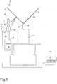
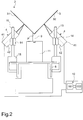
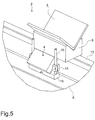
- Figures 1-7 show an apparatus 2 for measuring the bending angle of a sheet 3 in a press brake machine 1.
- the press brake machine 1 is typically provided with a die 9 ( figures 1 , 2 , 4-7 ) supported by a support 11; die 9 is of the interchangeable type to allow various bending types.
- the press brake machine 1 comprises a bending blade 12 ( figures 6 , 7 ) actuated by a mechanical assembly 13 so as to impress a longitudinal fold according to a line P on the sheet 3, interposed between die 9 and bending blade 12.
- reference numerals 31 and 32 are the two surfaces or sides of sheet 3 adjacent to the bending line P, with the sheet 3 either during or after the step of bending.
- the measuring apparatus 2 comprises at least one sensor 4 ( figure 1 ) comprising a recording means 41, e.g. a video camera or photo camera, and a structured light illuminating source 42, e.g. a laser; two sensors 4 are preferably included ( figure 2 ).
- a recording means 41 e.g. a video camera or photo camera
- a structured light illuminating source 42 e.g. a laser
- two sensors 4 are preferably included ( figure 2 ).
- Each sensor 4 is supported by a clamp 14 and is adjustable in height by means of rods 15 on which clamp 14 can slide.
- Said rods 15 are integral with a support element 16 sliding along guides 8 which are longitudinal with respect to die 9.
- the light source 42 is adapted to project a light pattern on a surface 31, 32 of the sheet 3.
- a light pattern means any geometric shape, a line, a plurality of parallel lines or incident lines or a point array.
- the recording means 41 are adapted to record the image of the light pattern projected by the light source 42 on the surface 31, 32 of sheet 3, i.e. the deformed light pattern projected on the sheet being bent.
- the recording means 41 and the lighting source 42 are connected to a processing unit 10 comprising a microprocessor 101 and a memory 102 on which an application software is installed and runs.
- the processing unit 10 may be considered as a set of sections or parts for controlling devices 41, 42 and for processing the images recorded by the recording means 41.
- the sections correspond to the various functions of the application software installed and running in memory 102.
- the processing unit 10 ( figure 8 ) comprises a section 110 adapted to control the light source 42 for illuminating the surface 31, 32 of sheet 3 and adapted to subsequently control the recording means 41 for recording the image obtained on the surface 31, 32 by the projection of the light pattern resulting from source 42.
- the camera means 41 are configured to record the image obtained on the surface 31, 32 by the projection of the light pattern during the operation of bending sheet 3 at least in one time instant Treg1 but preferably in a plurality of subsequent time instants Treg1, Treg2....Tregn, spaced apart by time intervals Td which are not zero until the required measuring value of the bending angle of sheet 3 is achieved.
- the time intervals Td preferably have the same duration, i.e. 15 milliseconds.
- the light pattern preferably comprises a plurality of lines 52 inclined with respect to one another and projected either parallel or essentially parallel to the surface 31, 32 of sheet 3 ( figure 3 ).
- the number of inclined lines 52 may be two or three.
- the recording means 41 record the image 55 during the operation of bending sheet 3 at least in one time instant Treg1, but preferably in time instants Treg1, Teg2... Tregn.
- the image of the deformed pattern 55 is sent to the processing unit 10, in particular to the section 111, by means of a wired or wireless connection.
- the processing unit 10 preferably applies a mask 51 for concealing die 9 in the recorded image 55 so as to ignore the portion of light pattern projected onto the die 9 itself.
- the processing unit 10 again in section 112, then processes the light sources of the recorded image 55 to discriminate the laser light pattern from the background represented by the surface 31, 32 of sheet 3; the recorded light pattern 56 is obtained in this manner.
- the processing unit 10, in section 113, is adapted to process said recorded pattern 56 to obtain a point cloud 57.
- Another section 114 of the processing unit 10 is adapted to sample the points of the point cloud 57 in order to reduce the amount of data to be processed; a plurality of samples 58 is obtained which, after a reassembly step again in section 114, are input to another section 115 comprising a neural network.
- Samples 58 may be chosen in a random manner. In all cases, the samples preferably refer to an area 300 of the surface 31, 32 of sheet 3 over die 9, preferably at a distance of 20 millimeters from die 9; thereby, by choosing the samples in the area 300 a greater measuring accuracy and fastening measuring operation speed is obtained.
- the number of samples 58 preferably varies from 200 to 300.
- the neural network 115 can detect a bending angle on the basis of the configuration of the points input thereto, i.e. according to the plurality of samples 58 which are supplied as inputs.
- the neural network 115 should be trained to provide a bending angle from samples of a point cloud before being used, i.e. should have previously processed an appropriate amount of configurations.
- the neural network 115 can suggest a linearization of the problem for which a solution is sought.
- a linearization expresses the statistic probability that a new case, never examined before, falls within a solution area which has been already checked and validated during the step of training.
- This result is intrinsically capable of compressing an amount of data because, once the numerical model has been learnt, the neutral network does not need to access a database from where to pick the correspondences between configurations of points and bending angle, as it is capable of autonomously reconstructing them.
- the training is further sampled, i.e. an amount of data to be stored is smaller because the neural network can reconstruct the remaining data by interpolation.
- the neural network 115 thus learns the relationships between the input variable (plurality of samples of the point cloud) and the output variable (bending angle) and is proven to be able to reproduce not only the point configurations which were never found before but also those which have already been seen, not needing to have a database of images available.
- working with point clouds does not require algorithms to solve the problem of image distortion which would occur in case of measurement strategies based on distance calculation (e.g. the angle between two lines).
- the bending angle 60 at the output from the neural network 115 is input into a section 116 which checks whether the bending angle 60 is equal to that desired. If the check is negative, the measurement of the bending angle of sheet 3 is repeated in subsequent time instants Treg1, Teg2...Tregn until a desired measurement angle value is achieved, i.e. until the checking operation is positive; whenever the operation is negative, section 116 informs the control section 110 to control the recording means and make a new recording of the image obtained on the surface 31, 32 by the projection of light pattern resulting from the source 42. Section 116 also preferably checks coherence of data output from the neural network 115; in case of positive result of both the coherence check operation and the checking operation, the measurement value 200 is sent to the user.
- the processing unit 10 works in the following manner ( figure 9 ).
- first step A of controlling the projection of the light pattern on one or both surfaces 31, 32 of sheet 3 and a step B of recording the image obtained on the surface 31, 32 by the light pattern projection during the operation of bending sheet 3 in a time instant Treg1.
- step C of applying a mask 51 for concealing die 9 in the recorded image 55, and a step D of discriminating the laser light pattern from the background represented by the surface 31, 32 of sheet 3 so as to obtain a recorded light pattern 56.
- step E of transforming the recorded light pattern 56 into a point cloud 57
- step F of sampling the point cloud 57 in order to obtain a plurality of samples 58
- step of reassembling the samples there are a step E of transforming the recorded light pattern 56 into a point cloud 57, and a subsequent step F of sampling the point cloud 57 in order to obtain a plurality of samples 58.
- the plurality of reassembled samples 58 are processed by a neural network for identifying the bending angle 60 corresponding to said plurality of reassembled samples 58.
- the coherence of the bending angle 60 is preferably checked during a subsequent step H; in case of positive result (Yes), the value 60 of the bending angle is the output for the subsequent step L, otherwise (No) step G resumes.
- step L there is a step of checking in which it is evaluated whether the value 60 of the bending angle obtained in the time instant Treg1 is the one desired; if this is so (Yes), the measuring method ends, otherwise (NO) another measurement of the bending angle is made in a subsequent instant Treg2, after a time interval Td from instant Treg1 i.e. the measuring method resumes from step B or, if the projection of light pattern on one or both surfaces 31, 32 of sheet 3 is also not continuous but discontinuous, the measuring method resumes from step A by controlling the projection of the light pattern.
- step L there is a new step of checking in which it is evaluated whether the value of measurement 60 of the bending angle obtained in time instant Treg2 is the desired one; if this is so (Yes), the measuring method ends, otherwise (NO) another measurement of the bending angle is carried out in a later instant Treg3, after the time interval Td of instant Treg2, i.e. a measuring method resumes from step B or A again.
- the measuring method continues in the subsequent instants Treg3...Tregn until it is checked that at step L the measurement value obtained is that desired and the measuring value 200 is thus transmitted to the user.
Landscapes
- Physics & Mathematics (AREA)
- General Physics & Mathematics (AREA)
- Engineering & Computer Science (AREA)
- Mechanical Engineering (AREA)
- Bending Of Plates, Rods, And Pipes (AREA)
- Length Measuring Devices By Optical Means (AREA)
- Image Analysis (AREA)
- Image Processing (AREA)
Priority Applications (1)
| Application Number | Priority Date | Filing Date | Title |
|---|---|---|---|
| PL13166167T PL2660559T3 (pl) | 2012-05-04 | 2013-05-02 | Urządzenie i sposób mierzenia kąta zgięcia arkusza |
Applications Claiming Priority (1)
| Application Number | Priority Date | Filing Date | Title |
|---|---|---|---|
| IT000751A ITMI20120751A1 (it) | 2012-05-04 | 2012-05-04 | Apparato e metodo per la misurazione dell'angolo di piegatura di una lamiera. |
Publications (2)
| Publication Number | Publication Date |
|---|---|
| EP2660559A1 EP2660559A1 (en) | 2013-11-06 |
| EP2660559B1 true EP2660559B1 (en) | 2017-09-06 |
Family
ID=46397414
Family Applications (1)
| Application Number | Title | Priority Date | Filing Date |
|---|---|---|---|
| EP13166167.0A Active EP2660559B1 (en) | 2012-05-04 | 2013-05-02 | Apparatus and method for measuring the bending angle of a sheet |
Country Status (12)
| Country | Link |
|---|---|
| US (1) | US9289810B2 (da) |
| EP (1) | EP2660559B1 (da) |
| JP (1) | JP2013234994A (da) |
| KR (1) | KR101937902B1 (da) |
| CN (1) | CN103381436B (da) |
| BR (1) | BR102013010743B1 (da) |
| CA (1) | CA2813641A1 (da) |
| DK (1) | DK2660559T3 (da) |
| ES (1) | ES2647529T3 (da) |
| IT (1) | ITMI20120751A1 (da) |
| PL (1) | PL2660559T3 (da) |
| RU (1) | RU2642999C2 (da) |
Families Citing this family (18)
| Publication number | Priority date | Publication date | Assignee | Title |
|---|---|---|---|---|
| PL2719475T3 (pl) * | 2012-10-12 | 2019-05-31 | Nivora Ip B V | Układ pomiarowy oraz sposób pomiaru kąta |
| CN103438835B (zh) * | 2013-08-23 | 2016-06-08 | 中联重科股份有限公司 | 一种板材折弯角度检测装置和方法 |
| AT515671B1 (de) * | 2014-06-23 | 2015-11-15 | Trumpf Maschinen Austria Gmbh | Biegewinkelmessvorrichtung für eine Biegepresse |
| AT515521B1 (de) | 2014-07-23 | 2015-10-15 | Trumpf Maschinen Austria Gmbh | Biegewinkelmessvorrichtung und Verfahren zum Messen eines Biegewinkels mittels der Biegewinkelmessvorrichtung |
| EP2982933B1 (en) | 2014-08-07 | 2021-03-24 | SALVAGNINI ITALIA S.p.A. | Apparatus and method for measuring a bending angle of a workpiece |
| AT515944B1 (de) * | 2014-10-16 | 2016-01-15 | Trumpf Maschinen Austria Gmbh | Biegewinkel-Messverfahren |
| US10365092B2 (en) * | 2015-05-28 | 2019-07-30 | Keba Ag | Electronic angle measuring device for a bending machine for measuring the bending angle between the legs of a metal sheet |
| US11027323B2 (en) | 2016-06-10 | 2021-06-08 | Advanced Orthodontic Solutions | Method and apparatus for auto-calibration of a wire bending machine |
| US11010506B2 (en) * | 2017-03-28 | 2021-05-18 | Hexagon Technology Center Gmbh | Method for designing a die surface |
| CN108151676A (zh) * | 2017-12-27 | 2018-06-12 | 福建省永正工程质量检测有限公司 | 一种建筑安装用弯管机折弯角度检测装置 |
| AT522419B1 (de) * | 2019-04-11 | 2021-11-15 | Trumpf Maschinen Austria Gmbh & Co Kg | Messvorrichtung zur Bestimmung des Biegewinkels |
| CN110411377B (zh) * | 2019-06-11 | 2021-09-28 | 湖北光安伦芯片有限公司 | 一种直角检测调节系统及方法 |
| CN113118307B (zh) * | 2021-03-24 | 2023-03-21 | 深圳市亿和精密科技集团有限公司 | 一种一步式负角结构折弯成型模具 |
| EP4063783A1 (de) * | 2021-03-25 | 2022-09-28 | Bystronic Laser AG | Verfahren und vorrichtung zur biegewinkelbestimmung an einer biegemaschine |
| CN115780567A (zh) * | 2022-10-13 | 2023-03-14 | 武汉理工大学 | 一种板材折弯角度检测装置和方法 |
| CN115921605A (zh) * | 2022-12-06 | 2023-04-07 | 扬州市职业大学(扬州开放大学) | 一种基于3d视觉技术的折弯角度实时测量方法及装置 |
| KR102918912B1 (ko) * | 2023-01-26 | 2026-01-28 | 인하대학교 산학협력단 | 레이저 센서를 이용한 흙막이 벽체 변위 계측 장치 제어 시스템 |
| CN119327919B (zh) * | 2024-10-18 | 2025-09-19 | 湖北志特新材料科技有限公司 | 一种具有检测结构的铝板折弯设备及使用方法 |
Citations (1)
| Publication number | Priority date | Publication date | Assignee | Title |
|---|---|---|---|---|
| US5103488A (en) * | 1989-06-21 | 1992-04-07 | Cselt Centro Studi E Laboratori Telecommunicazioni Spa | Method of and device for moving image contour recognition |
Family Cites Families (21)
| Publication number | Priority date | Publication date | Assignee | Title |
|---|---|---|---|---|
| JPH0381033A (ja) * | 1989-08-23 | 1991-04-05 | Amada Co Ltd | プレス用金型ダイ及び曲げプレスに於ける曲げ角度検出装置及び曲げプレス制御装置 |
| JPH0571933A (ja) * | 1991-09-11 | 1993-03-23 | Shin Meiwa Ind Co Ltd | 視覚センサシステム |
| JP2641829B2 (ja) * | 1992-11-10 | 1997-08-20 | 株式会社小松製作所 | 曲げ加工機における曲げ角度検出装置 |
| JPH0777416A (ja) * | 1993-09-08 | 1995-03-20 | Tipton Mfg Corp | ニューラルネットワークによる表面粗さ測定方法及び測定装置 |
| US5761940A (en) * | 1994-11-09 | 1998-06-09 | Amada Company, Ltd. | Methods and apparatuses for backgaging and sensor-based control of bending operations |
| JPH10160434A (ja) * | 1996-12-02 | 1998-06-19 | Yasuyuki Moriyama | 折曲げ機用角度検出方法およびその角度検出装置 |
| EP1127633A4 (en) * | 1998-08-10 | 2008-06-11 | Amada Co Ltd | METHOD FOR MEASURING A CORNER ANGLE AND CORRESPONDING APPARATUS, BENDING TECHNIQUE, AND APPARATUS FOR ACTING ON THE BENDING ANGLE |
| DE19939837A1 (de) * | 1999-08-21 | 2001-03-29 | Eht Werkzeugmaschinen Gmbh | Verfahren und Vorrichtung zum Erfassen eines Biegewinkels an einem Werkstück |
| ES2251150T3 (es) * | 1999-11-19 | 2006-04-16 | Lvd Company Nv | Metodo y dispositivo para medir un angulo de plegado de una chapa en una maquina plegadora. |
| RU2204454C2 (ru) * | 2000-08-02 | 2003-05-20 | Акционерное общество открытого типа "Научно-исследовательский технологический институт" (АООТ "НИТИ-ТЕСАР") | Устройство для контроля углов гибки и углов пружинения к трубогибочному станку |
| JP4683698B2 (ja) * | 2000-09-06 | 2011-05-18 | 株式会社アマダ電子 | 曲げ加工方法及びその装置 |
| FR2813054B1 (fr) * | 2000-08-21 | 2002-11-15 | Faure Bertrand Equipements Sa | Systeme pour vehicule, comportant un dispositif de commande adapte pour faire fonctionner un actionneur selectivement en fonction d'une valeur mesuree par un dispositif de mesure dispose dans un siege |
| JP2006205256A (ja) * | 2004-12-27 | 2006-08-10 | Amada Co Ltd | ワークの曲げ角度検出装置およびワークの曲げ加工機 |
| CN201094975Y (zh) * | 2007-08-13 | 2008-08-06 | 周宏� | 反馈式角度控制数控板料折弯机 |
| RU2366893C1 (ru) * | 2008-02-19 | 2009-09-10 | Российская Федерация, от имени которой выступает Государственный заказчик - Федеральное агентство по атомной энергии | Устройство измерения угловых и линейных координат объекта |
| CN101751487A (zh) * | 2008-12-18 | 2010-06-23 | 北京航空航天大学 | 利用人工神经网络的弯曲位移 |
| CN101655703B (zh) * | 2009-08-05 | 2013-03-13 | 无锡信捷电气有限公司 | 数控折弯机控制系统 |
| US8553989B1 (en) * | 2010-04-27 | 2013-10-08 | Hrl Laboratories, Llc | Three-dimensional (3D) object recognition system using region of interest geometric features |
| JP2012022600A (ja) * | 2010-07-16 | 2012-02-02 | Denso Wave Inc | マスク画像作成システム |
| JP5684550B2 (ja) * | 2010-12-03 | 2015-03-11 | 株式会社日立ハイテクノロジーズ | パターンマッチング装置およびそれを用いた半導体検査システム |
| RU107348U1 (ru) * | 2011-02-02 | 2011-08-10 | Открытое акционерное общество "ЛОМО" | Устройство для измерения угла |
-
2012
- 2012-05-04 IT IT000751A patent/ITMI20120751A1/it unknown
-
2013
- 2013-04-23 CA CA2813641A patent/CA2813641A1/en not_active Abandoned
- 2013-04-24 RU RU2013119136A patent/RU2642999C2/ru active
- 2013-04-25 JP JP2013092896A patent/JP2013234994A/ja active Pending
- 2013-04-30 BR BR102013010743-3A patent/BR102013010743B1/pt active IP Right Grant
- 2013-05-02 EP EP13166167.0A patent/EP2660559B1/en active Active
- 2013-05-02 PL PL13166167T patent/PL2660559T3/pl unknown
- 2013-05-02 DK DK13166167.0T patent/DK2660559T3/da active
- 2013-05-02 US US13/875,635 patent/US9289810B2/en active Active
- 2013-05-02 ES ES13166167.0T patent/ES2647529T3/es active Active
- 2013-05-03 KR KR1020130049880A patent/KR101937902B1/ko active Active
- 2013-05-03 CN CN201310159714.2A patent/CN103381436B/zh active Active
Patent Citations (1)
| Publication number | Priority date | Publication date | Assignee | Title |
|---|---|---|---|---|
| US5103488A (en) * | 1989-06-21 | 1992-04-07 | Cselt Centro Studi E Laboratori Telecommunicazioni Spa | Method of and device for moving image contour recognition |
Also Published As
| Publication number | Publication date |
|---|---|
| DK2660559T3 (da) | 2017-12-04 |
| RU2642999C2 (ru) | 2018-01-29 |
| BR102013010743B1 (pt) | 2020-10-27 |
| US20130291610A1 (en) | 2013-11-07 |
| CN103381436A (zh) | 2013-11-06 |
| BR102013010743A2 (pt) | 2015-06-23 |
| KR101937902B1 (ko) | 2019-01-11 |
| CN103381436B (zh) | 2017-03-01 |
| KR20130124218A (ko) | 2013-11-13 |
| ES2647529T3 (es) | 2017-12-22 |
| US9289810B2 (en) | 2016-03-22 |
| RU2013119136A (ru) | 2014-10-27 |
| ITMI20120751A1 (it) | 2013-11-05 |
| JP2013234994A (ja) | 2013-11-21 |
| CA2813641A1 (en) | 2013-11-04 |
| PL2660559T3 (pl) | 2018-02-28 |
| EP2660559A1 (en) | 2013-11-06 |
Similar Documents
| Publication | Publication Date | Title |
|---|---|---|
| EP2660559B1 (en) | Apparatus and method for measuring the bending angle of a sheet | |
| CN112710283B (zh) | 用于检测对象流的相机和用于确定对象高度的方法 | |
| CN102753313B (zh) | 用于在车辆上确定间距的方法和装置 | |
| US10464114B2 (en) | Bending tool having a longitudinal-offset measuring device | |
| JP7685536B2 (ja) | ビデオ伸び計システム及び方法のための厚さ補正 | |
| CN117621072B (zh) | 一种均匀喷涂机器人的路径规划方法 | |
| CN118863159B (zh) | 结合追踪监测的焊缝工艺动态优化方法及系统 | |
| JP4741344B2 (ja) | 形状認識装置及び歪評価装置 | |
| CN120347741A (zh) | 一种基于关节力矩的类人机器动作协调方法及系统 | |
| CN120489583B (zh) | 一种轨道车辆的车轮踏面离轨检测方法及系统 | |
| CN118458461A (zh) | 物件的纠偏方法及纠偏装置 | |
| KR102851569B1 (ko) | 기계 비전 검측방법, 이의 검측장치 및 이의 검측시스템 | |
| CN120354561A (zh) | 一种铜管材矫直动态补偿方法及系统 | |
| CN111222225B (zh) | 一种机器人中传感器位姿的确定方法及装置 | |
| JPWO2022191301A5 (da) | ||
| CN120620179A (zh) | 一种基于接近感知的机器人随动抓取方法及其相关设备 | |
| JP2007163340A (ja) | 板長さ測定装置及び板長さ測定方法 | |
| EP3563983B1 (en) | Method of, as well as a system for, performing a welding step on a work piece | |
| CN111076667B (zh) | 一种金属表面划痕动态快速测量方法 | |
| WO2013006109A1 (en) | Device and method for measuring deformation of a metal sheet | |
| JP7053889B2 (ja) | プレス成形品のネッキング判定方法、プレス成形品のネッキング判定装置、及びプログラム | |
| CN121600011A (zh) | 钢板轮廓检测方法、系统、电子设备及存储介质 | |
| CN120885437A (zh) | 一种基于机器视觉的包裹检测分拣方法及系统 | |
| CN120524973A (zh) | 一种纸垛点数的方法和装置 | |
| JP2023168958A (ja) | 情報処理装置、情報処理方法及びプログラム |
Legal Events
| Date | Code | Title | Description |
|---|---|---|---|
| PUAI | Public reference made under article 153(3) epc to a published international application that has entered the european phase |
Free format text: ORIGINAL CODE: 0009012 |
|
| AK | Designated contracting states |
Kind code of ref document: A1 Designated state(s): AL AT BE BG CH CY CZ DE DK EE ES FI FR GB GR HR HU IE IS IT LI LT LU LV MC MK MT NL NO PL PT RO RS SE SI SK SM TR |
|
| AX | Request for extension of the european patent |
Extension state: BA ME |
|
| 17P | Request for examination filed |
Effective date: 20140430 |
|
| RBV | Designated contracting states (corrected) |
Designated state(s): AL AT BE BG CH CY CZ DE DK EE ES FI FR GB GR HR HU IE IS IT LI LT LU LV MC MK MT NL NO PL PT RO RS SE SI SK SM TR |
|
| 17Q | First examination report despatched |
Effective date: 20160504 |
|
| STAA | Information on the status of an ep patent application or granted ep patent |
Free format text: STATUS: EXAMINATION IS IN PROGRESS |
|
| REG | Reference to a national code |
Ref country code: DE Ref legal event code: R079 Ref document number: 602013026039 Country of ref document: DE Free format text: PREVIOUS MAIN CLASS: G01B0011260000 Ipc: B21D0005000000 |
|
| GRAP | Despatch of communication of intention to grant a patent |
Free format text: ORIGINAL CODE: EPIDOSNIGR1 |
|
| STAA | Information on the status of an ep patent application or granted ep patent |
Free format text: STATUS: GRANT OF PATENT IS INTENDED |
|
| RIC1 | Information provided on ipc code assigned before grant |
Ipc: G01B 11/26 20060101ALI20170308BHEP Ipc: B21D 5/00 20060101AFI20170308BHEP |
|
| INTG | Intention to grant announced |
Effective date: 20170328 |
|
| RIN1 | Information on inventor provided before grant (corrected) |
Inventor name: NARDETTO, GIANFRANCO Inventor name: BATTISTELLI, FLAVIO |
|
| GRAS | Grant fee paid |
Free format text: ORIGINAL CODE: EPIDOSNIGR3 |
|
| GRAA | (expected) grant |
Free format text: ORIGINAL CODE: 0009210 |
|
| STAA | Information on the status of an ep patent application or granted ep patent |
Free format text: STATUS: THE PATENT HAS BEEN GRANTED |
|
| AK | Designated contracting states |
Kind code of ref document: B1 Designated state(s): AL AT BE BG CH CY CZ DE DK EE ES FI FR GB GR HR HU IE IS IT LI LT LU LV MC MK MT NL NO PL PT RO RS SE SI SK SM TR |
|
| REG | Reference to a national code |
Ref country code: GB Ref legal event code: FG4D |
|
| REG | Reference to a national code |
Ref country code: CH Ref legal event code: EP Ref country code: AT Ref legal event code: REF Ref document number: 925306 Country of ref document: AT Kind code of ref document: T Effective date: 20170915 |
|
| REG | Reference to a national code |
Ref country code: IE Ref legal event code: FG4D |
|
| REG | Reference to a national code |
Ref country code: DE Ref legal event code: R096 Ref document number: 602013026039 Country of ref document: DE |
|
| REG | Reference to a national code |
Ref country code: DK Ref legal event code: T3 Effective date: 20171128 |
|
| REG | Reference to a national code |
Ref country code: ES Ref legal event code: FG2A Ref document number: 2647529 Country of ref document: ES Kind code of ref document: T3 Effective date: 20171222 |
|
| REG | Reference to a national code |
Ref country code: SE Ref legal event code: TRGR |
|
| REG | Reference to a national code |
Ref country code: NL Ref legal event code: MP Effective date: 20170906 |
|
| REG | Reference to a national code |
Ref country code: LT Ref legal event code: MG4D |
|
| PG25 | Lapsed in a contracting state [announced via postgrant information from national office to epo] |
Ref country code: LT Free format text: LAPSE BECAUSE OF FAILURE TO SUBMIT A TRANSLATION OF THE DESCRIPTION OR TO PAY THE FEE WITHIN THE PRESCRIBED TIME-LIMIT Effective date: 20170906 Ref country code: HR Free format text: LAPSE BECAUSE OF FAILURE TO SUBMIT A TRANSLATION OF THE DESCRIPTION OR TO PAY THE FEE WITHIN THE PRESCRIBED TIME-LIMIT Effective date: 20170906 Ref country code: NO Free format text: LAPSE BECAUSE OF FAILURE TO SUBMIT A TRANSLATION OF THE DESCRIPTION OR TO PAY THE FEE WITHIN THE PRESCRIBED TIME-LIMIT Effective date: 20171206 |
|
| PG25 | Lapsed in a contracting state [announced via postgrant information from national office to epo] |
Ref country code: RS Free format text: LAPSE BECAUSE OF FAILURE TO SUBMIT A TRANSLATION OF THE DESCRIPTION OR TO PAY THE FEE WITHIN THE PRESCRIBED TIME-LIMIT Effective date: 20170906 Ref country code: BG Free format text: LAPSE BECAUSE OF FAILURE TO SUBMIT A TRANSLATION OF THE DESCRIPTION OR TO PAY THE FEE WITHIN THE PRESCRIBED TIME-LIMIT Effective date: 20171206 Ref country code: GR Free format text: LAPSE BECAUSE OF FAILURE TO SUBMIT A TRANSLATION OF THE DESCRIPTION OR TO PAY THE FEE WITHIN THE PRESCRIBED TIME-LIMIT Effective date: 20171207 Ref country code: LV Free format text: LAPSE BECAUSE OF FAILURE TO SUBMIT A TRANSLATION OF THE DESCRIPTION OR TO PAY THE FEE WITHIN THE PRESCRIBED TIME-LIMIT Effective date: 20170906 |
|
| PG25 | Lapsed in a contracting state [announced via postgrant information from national office to epo] |
Ref country code: NL Free format text: LAPSE BECAUSE OF FAILURE TO SUBMIT A TRANSLATION OF THE DESCRIPTION OR TO PAY THE FEE WITHIN THE PRESCRIBED TIME-LIMIT Effective date: 20170906 |
|
| PG25 | Lapsed in a contracting state [announced via postgrant information from national office to epo] |
Ref country code: RO Free format text: LAPSE BECAUSE OF FAILURE TO SUBMIT A TRANSLATION OF THE DESCRIPTION OR TO PAY THE FEE WITHIN THE PRESCRIBED TIME-LIMIT Effective date: 20170906 Ref country code: CZ Free format text: LAPSE BECAUSE OF FAILURE TO SUBMIT A TRANSLATION OF THE DESCRIPTION OR TO PAY THE FEE WITHIN THE PRESCRIBED TIME-LIMIT Effective date: 20170906 |
|
| REG | Reference to a national code |
Ref country code: FR Ref legal event code: PLFP Year of fee payment: 6 |
|
| PG25 | Lapsed in a contracting state [announced via postgrant information from national office to epo] |
Ref country code: EE Free format text: LAPSE BECAUSE OF FAILURE TO SUBMIT A TRANSLATION OF THE DESCRIPTION OR TO PAY THE FEE WITHIN THE PRESCRIBED TIME-LIMIT Effective date: 20170906 Ref country code: IS Free format text: LAPSE BECAUSE OF FAILURE TO SUBMIT A TRANSLATION OF THE DESCRIPTION OR TO PAY THE FEE WITHIN THE PRESCRIBED TIME-LIMIT Effective date: 20180106 Ref country code: SM Free format text: LAPSE BECAUSE OF FAILURE TO SUBMIT A TRANSLATION OF THE DESCRIPTION OR TO PAY THE FEE WITHIN THE PRESCRIBED TIME-LIMIT Effective date: 20170906 Ref country code: SK Free format text: LAPSE BECAUSE OF FAILURE TO SUBMIT A TRANSLATION OF THE DESCRIPTION OR TO PAY THE FEE WITHIN THE PRESCRIBED TIME-LIMIT Effective date: 20170906 |
|
| REG | Reference to a national code |
Ref country code: DE Ref legal event code: R097 Ref document number: 602013026039 Country of ref document: DE |
|
| PLBE | No opposition filed within time limit |
Free format text: ORIGINAL CODE: 0009261 |
|
| STAA | Information on the status of an ep patent application or granted ep patent |
Free format text: STATUS: NO OPPOSITION FILED WITHIN TIME LIMIT |
|
| 26N | No opposition filed |
Effective date: 20180607 |
|
| PG25 | Lapsed in a contracting state [announced via postgrant information from national office to epo] |
Ref country code: SI Free format text: LAPSE BECAUSE OF FAILURE TO SUBMIT A TRANSLATION OF THE DESCRIPTION OR TO PAY THE FEE WITHIN THE PRESCRIBED TIME-LIMIT Effective date: 20170906 |
|
| REG | Reference to a national code |
Ref country code: BE Ref legal event code: MM Effective date: 20180531 |
|
| PG25 | Lapsed in a contracting state [announced via postgrant information from national office to epo] |
Ref country code: MC Free format text: LAPSE BECAUSE OF FAILURE TO SUBMIT A TRANSLATION OF THE DESCRIPTION OR TO PAY THE FEE WITHIN THE PRESCRIBED TIME-LIMIT Effective date: 20170906 |
|
| REG | Reference to a national code |
Ref country code: IE Ref legal event code: MM4A |
|
| PG25 | Lapsed in a contracting state [announced via postgrant information from national office to epo] |
Ref country code: LU Free format text: LAPSE BECAUSE OF NON-PAYMENT OF DUE FEES Effective date: 20180502 |
|
| PG25 | Lapsed in a contracting state [announced via postgrant information from national office to epo] |
Ref country code: IE Free format text: LAPSE BECAUSE OF NON-PAYMENT OF DUE FEES Effective date: 20180502 |
|
| PG25 | Lapsed in a contracting state [announced via postgrant information from national office to epo] |
Ref country code: BE Free format text: LAPSE BECAUSE OF NON-PAYMENT OF DUE FEES Effective date: 20180531 |
|
| REG | Reference to a national code |
Ref country code: AT Ref legal event code: UEP Ref document number: 925306 Country of ref document: AT Kind code of ref document: T Effective date: 20170906 |
|
| PG25 | Lapsed in a contracting state [announced via postgrant information from national office to epo] |
Ref country code: MT Free format text: LAPSE BECAUSE OF NON-PAYMENT OF DUE FEES Effective date: 20180502 |
|
| PG25 | Lapsed in a contracting state [announced via postgrant information from national office to epo] |
Ref country code: PT Free format text: LAPSE BECAUSE OF FAILURE TO SUBMIT A TRANSLATION OF THE DESCRIPTION OR TO PAY THE FEE WITHIN THE PRESCRIBED TIME-LIMIT Effective date: 20170906 Ref country code: HU Free format text: LAPSE BECAUSE OF FAILURE TO SUBMIT A TRANSLATION OF THE DESCRIPTION OR TO PAY THE FEE WITHIN THE PRESCRIBED TIME-LIMIT; INVALID AB INITIO Effective date: 20130502 |
|
| PG25 | Lapsed in a contracting state [announced via postgrant information from national office to epo] |
Ref country code: CY Free format text: LAPSE BECAUSE OF FAILURE TO SUBMIT A TRANSLATION OF THE DESCRIPTION OR TO PAY THE FEE WITHIN THE PRESCRIBED TIME-LIMIT Effective date: 20170906 Ref country code: MK Free format text: LAPSE BECAUSE OF NON-PAYMENT OF DUE FEES Effective date: 20170906 |
|
| PG25 | Lapsed in a contracting state [announced via postgrant information from national office to epo] |
Ref country code: AL Free format text: LAPSE BECAUSE OF FAILURE TO SUBMIT A TRANSLATION OF THE DESCRIPTION OR TO PAY THE FEE WITHIN THE PRESCRIBED TIME-LIMIT Effective date: 20170906 |
|
| P01 | Opt-out of the competence of the unified patent court (upc) registered |
Effective date: 20230515 |
|
| PGFP | Annual fee paid to national office [announced via postgrant information from national office to epo] |
Ref country code: FI Payment date: 20250526 Year of fee payment: 13 |
|
| PGFP | Annual fee paid to national office [announced via postgrant information from national office to epo] |
Ref country code: PL Payment date: 20250418 Year of fee payment: 13 Ref country code: DE Payment date: 20250529 Year of fee payment: 13 |
|
| PGFP | Annual fee paid to national office [announced via postgrant information from national office to epo] |
Ref country code: ES Payment date: 20250602 Year of fee payment: 13 Ref country code: DK Payment date: 20250526 Year of fee payment: 13 |
|
| PGFP | Annual fee paid to national office [announced via postgrant information from national office to epo] |
Ref country code: IT Payment date: 20250521 Year of fee payment: 13 |
|
| PGFP | Annual fee paid to national office [announced via postgrant information from national office to epo] |
Ref country code: FR Payment date: 20250526 Year of fee payment: 13 |
|
| PGFP | Annual fee paid to national office [announced via postgrant information from national office to epo] |
Ref country code: CH Payment date: 20250601 Year of fee payment: 13 |
|
| PGFP | Annual fee paid to national office [announced via postgrant information from national office to epo] |
Ref country code: AT Payment date: 20250423 Year of fee payment: 13 |
|
| PGFP | Annual fee paid to national office [announced via postgrant information from national office to epo] |
Ref country code: TR Payment date: 20250428 Year of fee payment: 13 |
|
| PGFP | Annual fee paid to national office [announced via postgrant information from national office to epo] |
Ref country code: SE Payment date: 20250527 Year of fee payment: 13 |
|
| PGFP | Annual fee paid to national office [announced via postgrant information from national office to epo] |
Ref country code: GB Payment date: 20260327 Year of fee payment: 14 |