EP2672040A2 - Agencement de rail de guidage pour une porte - Google Patents
Agencement de rail de guidage pour une porte Download PDFInfo
- Publication number
- EP2672040A2 EP2672040A2 EP13002214.8A EP13002214A EP2672040A2 EP 2672040 A2 EP2672040 A2 EP 2672040A2 EP 13002214 A EP13002214 A EP 13002214A EP 2672040 A2 EP2672040 A2 EP 2672040A2
- Authority
- EP
- European Patent Office
- Prior art keywords
- guide rail
- locking device
- door
- cover
- longitudinal direction
- Prior art date
- Legal status (The legal status is an assumption and is not a legal conclusion. Google has not performed a legal analysis and makes no representation as to the accuracy of the status listed.)
- Withdrawn
Links
- 230000000284 resting effect Effects 0.000 claims 1
- 230000000295 complement effect Effects 0.000 description 4
- 239000000428 dust Substances 0.000 description 3
- 230000001419 dependent effect Effects 0.000 description 2
- 238000011109 contamination Methods 0.000 description 1
- 238000011161 development Methods 0.000 description 1
- 230000018109 developmental process Effects 0.000 description 1
- 238000009434 installation Methods 0.000 description 1
- 238000012423 maintenance Methods 0.000 description 1
- 210000001331 nose Anatomy 0.000 description 1
Images


Classifications
-
- E—FIXED CONSTRUCTIONS
- E05—LOCKS; KEYS; WINDOW OR DOOR FITTINGS; SAFES
- E05F—DEVICES FOR MOVING WINGS INTO OPEN OR CLOSED POSITION; CHECKS FOR WINGS; WING FITTINGS NOT OTHERWISE PROVIDED FOR, CONCERNED WITH THE FUNCTIONING OF THE WING
- E05F3/00—Closers or openers with braking devices, e.g. checks; Construction of pneumatic or liquid braking devices
- E05F3/22—Additional arrangements for closers, e.g. for holding the wing in opened or other position
- E05F3/221—Mechanical power-locks, e.g. for holding the wing open or for free-moving zones
-
- E—FIXED CONSTRUCTIONS
- E05—LOCKS; KEYS; WINDOW OR DOOR FITTINGS; SAFES
- E05F—DEVICES FOR MOVING WINGS INTO OPEN OR CLOSED POSITION; CHECKS FOR WINGS; WING FITTINGS NOT OTHERWISE PROVIDED FOR, CONCERNED WITH THE FUNCTIONING OF THE WING
- E05F3/00—Closers or openers with braking devices, e.g. checks; Construction of pneumatic or liquid braking devices
- E05F3/22—Additional arrangements for closers, e.g. for holding the wing in opened or other position
- E05F2003/228—Arrangements where the end of the closer arm is sliding in a track
-
- E—FIXED CONSTRUCTIONS
- E05—LOCKS; KEYS; WINDOW OR DOOR FITTINGS; SAFES
- E05F—DEVICES FOR MOVING WINGS INTO OPEN OR CLOSED POSITION; CHECKS FOR WINGS; WING FITTINGS NOT OTHERWISE PROVIDED FOR, CONCERNED WITH THE FUNCTIONING OF THE WING
- E05F3/00—Closers or openers with braking devices, e.g. checks; Construction of pneumatic or liquid braking devices
- E05F3/22—Additional arrangements for closers, e.g. for holding the wing in opened or other position
- E05F3/227—Additional arrangements for closers, e.g. for holding the wing in opened or other position mounted at the top of wings, e.g. details related to closer housings, covers, end caps or rails therefor
-
- E—FIXED CONSTRUCTIONS
- E05—LOCKS; KEYS; WINDOW OR DOOR FITTINGS; SAFES
- E05Y—INDEXING SCHEME ASSOCIATED WITH SUBCLASSES E05D AND E05F, RELATING TO CONSTRUCTION ELEMENTS, ELECTRIC CONTROL, POWER SUPPLY, POWER SIGNAL OR TRANSMISSION, USER INTERFACES, MOUNTING OR COUPLING, DETAILS, ACCESSORIES, AUXILIARY OPERATIONS NOT OTHERWISE PROVIDED FOR, APPLICATION THEREOF
- E05Y2201/00—Constructional elements; Accessories therefor
- E05Y2201/10—Covers; Housings
- E05Y2201/11—Covers
-
- E—FIXED CONSTRUCTIONS
- E05—LOCKS; KEYS; WINDOW OR DOOR FITTINGS; SAFES
- E05Y—INDEXING SCHEME ASSOCIATED WITH SUBCLASSES E05D AND E05F, RELATING TO CONSTRUCTION ELEMENTS, ELECTRIC CONTROL, POWER SUPPLY, POWER SIGNAL OR TRANSMISSION, USER INTERFACES, MOUNTING OR COUPLING, DETAILS, ACCESSORIES, AUXILIARY OPERATIONS NOT OTHERWISE PROVIDED FOR, APPLICATION THEREOF
- E05Y2201/00—Constructional elements; Accessories therefor
- E05Y2201/20—Brakes; Disengaging means; Holders; Stops; Valves; Accessories therefor
- E05Y2201/218—Holders
-
- E—FIXED CONSTRUCTIONS
- E05—LOCKS; KEYS; WINDOW OR DOOR FITTINGS; SAFES
- E05Y—INDEXING SCHEME ASSOCIATED WITH SUBCLASSES E05D AND E05F, RELATING TO CONSTRUCTION ELEMENTS, ELECTRIC CONTROL, POWER SUPPLY, POWER SIGNAL OR TRANSMISSION, USER INTERFACES, MOUNTING OR COUPLING, DETAILS, ACCESSORIES, AUXILIARY OPERATIONS NOT OTHERWISE PROVIDED FOR, APPLICATION THEREOF
- E05Y2900/00—Application of doors, windows, wings or fittings thereof
- E05Y2900/10—Application of doors, windows, wings or fittings thereof for buildings or parts thereof
- E05Y2900/13—Type of wing
- E05Y2900/132—Doors
Definitions
- the present invention relates to a guide rail assembly for a door and a Matbetxigeran extract, comprising the guide rail assembly.
- guide rail arrangements for doors in various configurations.
- guide rail arrangements are used in conjunction with door closers or door drives.
- guide rail arrangements in connection with sliding doors.
- Swing doors are usually operated with a door closer or a door drive.
- the door closer of the door drive is either stationary on the wall or frame or directly on the door leaf. If the door closer is located on the door leaf by way of example, the force from the output shaft of the door closer is transmitted via a lever to a movement element (also: sliding piece).
- This slider is in the guide rail (also: slide), which is fixed to the wall or frame, linearly guided. In order to fix the door leaf in its position, the slider is fixed by means of a locking device in the guide rail.
- the door closer can also be fixed to the wall or frame.
- the guide rail is attached to the door leaf.
- sliding doors which are guided linearly movable in guide rails.
- a moving element is guided in the guide rail.
- the door leaf is attached.
- the movement element is fixed in the guide rail.
- the mechanics for detecting the moving element or the slider often pollution, for example by Dust deposits, exposed. Furthermore, this mechanism is often visible by the user of the door.
- a guide rail assembly for a door comprising a guide rail for mounting on a door leaf, a frame or wall. Furthermore, a movement element guided linearly movably in the guide rail along a longitudinal direction is provided.
- a locking device is fixed. This locking device is designed to lock the movement element relative to the guide rail.
- the locking device is covered by a lid. This cover is inserted over the locking device in the guide rail. The lid prevents dust and other debris settling in the locking device and thus would lead to a limited functionality of the locking device. Furthermore, the locking device is no longer visible due to the lid by the user. This results in a handsome, smoothed surface of the entire guide rail assembly.
- the cover completely covers one side of the locking device, which is defined parallel to the longitudinal direction.
- the guide rail has a mounting surface. When installing the guide rail, this mounting surface rests on the door leaf, the frame or the wall. For example, mounting holes in the mounting surface, the guide rail is attached. Perpendicular to this mounting surface are two side walls of the guide rail. These two side walls are spaced apart, so that between these side walls, the moving element is guided and the locking device is fixed.
- the lid is parallel to the mounting surface and is particularly used between the two side walls. Particularly preferably, the lid is flush with the top of the two side walls.
- the lid is a closed, unbroken surface.
- the cover has on each side at least one latching lug or latching edge.
- the locking device is preferably designed so that it can be fixed at different positions within the guide rail. By the position of the locking device in the guide rail is defined at which position the door leaf is finally fixed.
- the cover in particular with the locking lugs or locking edges, can theoretically be used at any point of the guide rail. However, in order to predetermine the fitter a defined position of the lid directly above the locking device, it is preferably provided that the cover is positioned along the longitudinal direction by a form fit between the locking device and the lid. In particular, will For this purpose, a recess formed on the lid, wherein in the assembled state, this recess is positively placed on a portion of the locking device.
- the cover is longer in the longitudinal direction than the locking device.
- the cover extends in the direction of the movement element longer than the locking device.
- the invention further includes a door actuator assembly having a guide rail assembly and a door operator just described.
- the door operator may be a door operator, a door closer or a power door closer.
- the movement element is connected via a lever to an output shaft of this door operator.
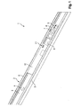
- the guide rail assembly 1 comprises a longitudinally extending guide rail 9 2.
- the guide rail 2 is composed of a mounting surface 3 and two parallel side walls 5.
- the two side walls 5 are spaced from each other and arranged perpendicular to the mounting surface 3.
- In the mounting surface 3 there are a plurality of mounting holes 4.
- the guide rail 2 is attached to a door leaf, a frame or a wall.
- the mounting surface 3 is on the door leaf, the frame or the wall.
- a moving element 6 is guided linearly movable along the longitudinal direction 9.
- the moving element 6 comprises an eye 7.
- a lever can be rotatably mounted.
- the power is transmitted to a door operator via this lever.
- the moving element 6 comprises a locking element 8, formed from locking lever.
- FIG. 2 shows an end view of the guide rail assembly 1.
- the guide rail 2 is hidden.
- a locking device 12 is arranged in the guide rail 2.
- This locking device 12 is shown here only schematically.
- the moving element 6 can be determined by means of the locking element 8.
- the locking element 8 is located within the locking device 12 is a not shown, complementary lever that blocks the locking element 8 on the moving element 6 and releases.
- FIG. 1 shows the locking device 12 is covered by a lid 10.
- a lid 10 On the lid 10 can optionally be applied a logo 11.
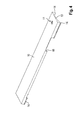
- FIG. 2 shows a concave bulge 13 on the inside of the lid 10. By this concave bulge 13 acts a certain spring force on the locking edges 14, so that the lid 10 braced between the two side walls 5.
- FIGS 3 and 4 show a recess 18 in the lid 10.
- a protruding portion 19 is provided on the locking device 12.
- the recess 18 is seated on the protruding portion 19, so that the position of the lid 10 is defined directly above the locking device 12. It is thus not possible to move the lid 10.
- FIG. 3 shows a lid length 16, which is measured parallel to the longitudinal direction 9. Furthermore, a locking device length 17 is also shown parallel to the longitudinal direction 9.
- the cover length 16 is substantially longer than the Feststellvoriquessus 17. This is, in the detected state of the moving element 6 and a part of the moving element 6, namely the locking element 8, covered by the cover 10. In particular, the cover 10 protrudes so far in the direction of the movement element 6 on the locking device 12 that in the locked state of the moving element 6, the complete locking element 8 is covered by the cover 10.
Landscapes
- Engineering & Computer Science (AREA)
- Mechanical Engineering (AREA)
- Support Devices For Sliding Doors (AREA)
- Power-Operated Mechanisms For Wings (AREA)
Applications Claiming Priority (1)
| Application Number | Priority Date | Filing Date | Title |
|---|---|---|---|
| DE102012104854A DE102012104854A1 (de) | 2012-06-05 | 2012-06-05 | Führungsschienenanordnung für eine Tür |
Publications (2)
| Publication Number | Publication Date |
|---|---|
| EP2672040A2 true EP2672040A2 (fr) | 2013-12-11 |
| EP2672040A3 EP2672040A3 (fr) | 2017-05-03 |
Family
ID=48190060
Family Applications (1)
| Application Number | Title | Priority Date | Filing Date |
|---|---|---|---|
| EP13002214.8A Withdrawn EP2672040A3 (fr) | 2012-06-05 | 2013-04-26 | Agencement de rail de guidage pour une porte |
Country Status (2)
| Country | Link |
|---|---|
| EP (1) | EP2672040A3 (fr) |
| DE (1) | DE102012104854A1 (fr) |
Family Cites Families (3)
| Publication number | Priority date | Publication date | Assignee | Title |
|---|---|---|---|---|
| FR2610979A1 (fr) * | 1987-02-18 | 1988-08-19 | Houdaille Lelaurain Sa | Dispositif dit selecteur de porte perfectionne |
| DE102005001313A1 (de) * | 2005-01-11 | 2006-07-27 | Dorma Gmbh + Co. Kg | Gleitschiene für einen Gleitschienen-Türschließer für zweiflügelige Türen |
| DE102008056214B4 (de) * | 2008-11-06 | 2014-09-25 | Assa Abloy Sicherheitstechnik Gmbh | Arretiereinheit für einen Türschließer, Türschließsystem, Verwendung einer Arretiereinheit und Verfahren zum Arretieren einer Tür |
-
2012
- 2012-06-05 DE DE102012104854A patent/DE102012104854A1/de not_active Withdrawn
-
2013
- 2013-04-26 EP EP13002214.8A patent/EP2672040A3/fr not_active Withdrawn
Non-Patent Citations (1)
| Title |
|---|
| None |
Also Published As
| Publication number | Publication date |
|---|---|
| DE102012104854A1 (de) | 2013-12-05 |
| EP2672040A3 (fr) | 2017-05-03 |
Similar Documents
| Publication | Publication Date | Title |
|---|---|---|
| EP2851497B1 (fr) | Dispositif de montage réglable pour un élément coulissant et dispositif coulissant | |
| EP2672042A2 (fr) | Agencement de rail de guidage | |
| EP2634350B1 (fr) | Joint amovible, notamment joint de porte coulissante | |
| EP2840214A1 (fr) | Dispositif ferme-porte | |
| EP2078812A2 (fr) | Elément de recouvrement pour un rail de guidage | |
| AT520645B1 (de) | Verriegelungsvorrichtung für eine Tür, insbesondere Schiebetür | |
| EP1620611B1 (fr) | Dispositif de fixation d'une paroi coulissante | |
| EP2672041A2 (fr) | Agencement de rail de guidage | |
| DE102011001679A1 (de) | Schliessplatte für einen von einem Blendrahmen abstellbaren Fenster-oder Türflügel | |
| EP2672040A2 (fr) | Agencement de rail de guidage pour une porte | |
| EP3371397B1 (fr) | Ensemble ferrure | |
| EP2672046A2 (fr) | Agencement de rail de guidage | |
| DE102014216722A1 (de) | Steuerelement für eine Beschlaganordnung | |
| DE102013212650C5 (de) | Vorrichtung zur Regelung der Schließfolge einer zweiflügeligen Drehtüranlage | |
| DE202014010097U1 (de) | Türschließblechanordnung und Türanordnung mit einer solchen | |
| EP2672043A2 (fr) | Agencement de rails de guidage | |
| EP2636833A1 (fr) | Ensemble de rail de guidage | |
| DE102012213782B4 (de) | Verlagerungsanordnung zur Verlagerung eines Schiebeflügels eines Fensters, einer Tür oder dergleichen relativ zu einer festen Einfassung mit einem flügelseitigen und einem einfassungsseitigen Steuerelement | |
| EP2636824A2 (fr) | Dispositif de fixation | |
| DE102014217711B4 (de) | Kulissenanordnung für eine Beschlagteilanordnung | |
| EP2722472A2 (fr) | Ferrure pour battant et séparation de douche | |
| DE102004051445A1 (de) | Verschiebbarer Deckel | |
| DE102014106063B4 (de) | Positioniervorrichtung | |
| EP2672048A2 (fr) | Agencement d'actionnement de porte | |
| DE102015008324A1 (de) | Gehäuse |
Legal Events
| Date | Code | Title | Description |
|---|---|---|---|
| PUAI | Public reference made under article 153(3) epc to a published international application that has entered the european phase |
Free format text: ORIGINAL CODE: 0009012 |
|
| AK | Designated contracting states |
Kind code of ref document: A2 Designated state(s): AL AT BE BG CH CY CZ DE DK EE ES FI FR GB GR HR HU IE IS IT LI LT LU LV MC MK MT NL NO PL PT RO RS SE SI SK SM TR |
|
| AX | Request for extension of the european patent |
Extension state: BA ME |
|
| RAP1 | Party data changed (applicant data changed or rights of an application transferred) |
Owner name: DORMA DEUTSCHLAND GMBH |
|
| PUAL | Search report despatched |
Free format text: ORIGINAL CODE: 0009013 |
|
| AK | Designated contracting states |
Kind code of ref document: A3 Designated state(s): AL AT BE BG CH CY CZ DE DK EE ES FI FR GB GR HR HU IE IS IT LI LT LU LV MC MK MT NL NO PL PT RO RS SE SI SK SM TR |
|
| AX | Request for extension of the european patent |
Extension state: BA ME |
|
| RAP1 | Party data changed (applicant data changed or rights of an application transferred) |
Owner name: DORMAKABA DEUTSCHLAND GMBH |
|
| RIC1 | Information provided on ipc code assigned before grant |
Ipc: E05C 17/60 20060101AFI20170329BHEP Ipc: E05F 3/22 20060101ALI20170329BHEP |
|
| STAA | Information on the status of an ep patent application or granted ep patent |
Free format text: STATUS: THE APPLICATION HAS BEEN PUBLISHED |
|
| RBV | Designated contracting states (corrected) |
Designated state(s): AL AT BE BG CH CY CZ DE DK EE ES FI FR GB GR HR HU IE IS IT LI LT LU LV MC MK MT NL NO PL PT RO RS SE SI SK SM TR |
|
| STAA | Information on the status of an ep patent application or granted ep patent |
Free format text: STATUS: REQUEST FOR EXAMINATION WAS MADE |
|
| STAA | Information on the status of an ep patent application or granted ep patent |
Free format text: STATUS: THE APPLICATION IS DEEMED TO BE WITHDRAWN |
|
| 17P | Request for examination filed |
Effective date: 20180202 |
|
| 18D | Application deemed to be withdrawn |
Effective date: 20171104 |