EP2672202B1 - Klimaanlage - Google Patents
Klimaanlage Download PDFInfo
- Publication number
- EP2672202B1 EP2672202B1 EP11857679.2A EP11857679A EP2672202B1 EP 2672202 B1 EP2672202 B1 EP 2672202B1 EP 11857679 A EP11857679 A EP 11857679A EP 2672202 B1 EP2672202 B1 EP 2672202B1
- Authority
- EP
- European Patent Office
- Prior art keywords
- refrigerant
- heat medium
- heat exchanger
- pressure
- expansion device
- Prior art date
- Legal status (The legal status is an assumption and is not a legal conclusion. Google has not performed a legal analysis and makes no representation as to the accuracy of the status listed.)
- Active
Links
Images




Classifications
-
- F—MECHANICAL ENGINEERING; LIGHTING; HEATING; WEAPONS; BLASTING
- F25—REFRIGERATION OR COOLING; COMBINED HEATING AND REFRIGERATION SYSTEMS; HEAT PUMP SYSTEMS; MANUFACTURE OR STORAGE OF ICE; LIQUEFACTION SOLIDIFICATION OF GASES
- F25B—REFRIGERATION MACHINES, PLANTS OR SYSTEMS; COMBINED HEATING AND REFRIGERATION SYSTEMS; HEAT PUMP SYSTEMS
- F25B29/00—Combined heating and refrigeration systems, e.g. operating alternately or simultaneously
- F25B29/003—Combined heating and refrigeration systems, e.g. operating alternately or simultaneously of the compression type system
-
- F—MECHANICAL ENGINEERING; LIGHTING; HEATING; WEAPONS; BLASTING
- F25—REFRIGERATION OR COOLING; COMBINED HEATING AND REFRIGERATION SYSTEMS; HEAT PUMP SYSTEMS; MANUFACTURE OR STORAGE OF ICE; LIQUEFACTION SOLIDIFICATION OF GASES
- F25B—REFRIGERATION MACHINES, PLANTS OR SYSTEMS; COMBINED HEATING AND REFRIGERATION SYSTEMS; HEAT PUMP SYSTEMS
- F25B1/00—Compression machines, plants or systems with non-reversible cycle
- F25B1/10—Compression machines, plants or systems with non-reversible cycle with multi-stage compression
-
- F—MECHANICAL ENGINEERING; LIGHTING; HEATING; WEAPONS; BLASTING
- F25—REFRIGERATION OR COOLING; COMBINED HEATING AND REFRIGERATION SYSTEMS; HEAT PUMP SYSTEMS; MANUFACTURE OR STORAGE OF ICE; LIQUEFACTION SOLIDIFICATION OF GASES
- F25B—REFRIGERATION MACHINES, PLANTS OR SYSTEMS; COMBINED HEATING AND REFRIGERATION SYSTEMS; HEAT PUMP SYSTEMS
- F25B13/00—Compression machines, plants or systems, with reversible cycle
-
- F—MECHANICAL ENGINEERING; LIGHTING; HEATING; WEAPONS; BLASTING
- F25—REFRIGERATION OR COOLING; COMBINED HEATING AND REFRIGERATION SYSTEMS; HEAT PUMP SYSTEMS; MANUFACTURE OR STORAGE OF ICE; LIQUEFACTION SOLIDIFICATION OF GASES
- F25B—REFRIGERATION MACHINES, PLANTS OR SYSTEMS; COMBINED HEATING AND REFRIGERATION SYSTEMS; HEAT PUMP SYSTEMS
- F25B2313/00—Compression machines, plants or systems with reversible cycle not otherwise provided for
- F25B2313/023—Compression machines, plants or systems with reversible cycle not otherwise provided for using multiple indoor units
-
- F—MECHANICAL ENGINEERING; LIGHTING; HEATING; WEAPONS; BLASTING
- F25—REFRIGERATION OR COOLING; COMBINED HEATING AND REFRIGERATION SYSTEMS; HEAT PUMP SYSTEMS; MANUFACTURE OR STORAGE OF ICE; LIQUEFACTION SOLIDIFICATION OF GASES
- F25B—REFRIGERATION MACHINES, PLANTS OR SYSTEMS; COMBINED HEATING AND REFRIGERATION SYSTEMS; HEAT PUMP SYSTEMS
- F25B2313/00—Compression machines, plants or systems with reversible cycle not otherwise provided for
- F25B2313/023—Compression machines, plants or systems with reversible cycle not otherwise provided for using multiple indoor units
- F25B2313/0231—Compression machines, plants or systems with reversible cycle not otherwise provided for using multiple indoor units with simultaneous cooling and heating
-
- F—MECHANICAL ENGINEERING; LIGHTING; HEATING; WEAPONS; BLASTING
- F25—REFRIGERATION OR COOLING; COMBINED HEATING AND REFRIGERATION SYSTEMS; HEAT PUMP SYSTEMS; MANUFACTURE OR STORAGE OF ICE; LIQUEFACTION SOLIDIFICATION OF GASES
- F25B—REFRIGERATION MACHINES, PLANTS OR SYSTEMS; COMBINED HEATING AND REFRIGERATION SYSTEMS; HEAT PUMP SYSTEMS
- F25B2313/00—Compression machines, plants or systems with reversible cycle not otherwise provided for
- F25B2313/027—Compression machines, plants or systems with reversible cycle not otherwise provided for characterised by the reversing means
- F25B2313/0272—Compression machines, plants or systems with reversible cycle not otherwise provided for characterised by the reversing means using bridge circuits of one-way valves
-
- F—MECHANICAL ENGINEERING; LIGHTING; HEATING; WEAPONS; BLASTING
- F25—REFRIGERATION OR COOLING; COMBINED HEATING AND REFRIGERATION SYSTEMS; HEAT PUMP SYSTEMS; MANUFACTURE OR STORAGE OF ICE; LIQUEFACTION SOLIDIFICATION OF GASES
- F25B—REFRIGERATION MACHINES, PLANTS OR SYSTEMS; COMBINED HEATING AND REFRIGERATION SYSTEMS; HEAT PUMP SYSTEMS
- F25B2313/00—Compression machines, plants or systems with reversible cycle not otherwise provided for
- F25B2313/027—Compression machines, plants or systems with reversible cycle not otherwise provided for characterised by the reversing means
- F25B2313/02732—Compression machines, plants or systems with reversible cycle not otherwise provided for characterised by the reversing means using two three-way valves
-
- F—MECHANICAL ENGINEERING; LIGHTING; HEATING; WEAPONS; BLASTING
- F25—REFRIGERATION OR COOLING; COMBINED HEATING AND REFRIGERATION SYSTEMS; HEAT PUMP SYSTEMS; MANUFACTURE OR STORAGE OF ICE; LIQUEFACTION SOLIDIFICATION OF GASES
- F25B—REFRIGERATION MACHINES, PLANTS OR SYSTEMS; COMBINED HEATING AND REFRIGERATION SYSTEMS; HEAT PUMP SYSTEMS
- F25B2313/00—Compression machines, plants or systems with reversible cycle not otherwise provided for
- F25B2313/027—Compression machines, plants or systems with reversible cycle not otherwise provided for characterised by the reversing means
- F25B2313/02741—Compression machines, plants or systems with reversible cycle not otherwise provided for characterised by the reversing means using one four-way valve
-
- F—MECHANICAL ENGINEERING; LIGHTING; HEATING; WEAPONS; BLASTING
- F25—REFRIGERATION OR COOLING; COMBINED HEATING AND REFRIGERATION SYSTEMS; HEAT PUMP SYSTEMS; MANUFACTURE OR STORAGE OF ICE; LIQUEFACTION SOLIDIFICATION OF GASES
- F25B—REFRIGERATION MACHINES, PLANTS OR SYSTEMS; COMBINED HEATING AND REFRIGERATION SYSTEMS; HEAT PUMP SYSTEMS
- F25B2400/00—Component parts or details not otherwise provided for in this subclass
- F25B2400/12—Inflammable refrigerants
- F25B2400/121—Inflammable refrigerants using R1234
-
- F—MECHANICAL ENGINEERING; LIGHTING; HEATING; WEAPONS; BLASTING
- F25—REFRIGERATION OR COOLING; COMBINED HEATING AND REFRIGERATION SYSTEMS; HEAT PUMP SYSTEMS; MANUFACTURE OR STORAGE OF ICE; LIQUEFACTION SOLIDIFICATION OF GASES
- F25B—REFRIGERATION MACHINES, PLANTS OR SYSTEMS; COMBINED HEATING AND REFRIGERATION SYSTEMS; HEAT PUMP SYSTEMS
- F25B25/00—Machines, plants or systems, using a combination of modes of operation covered by two or more of the groups F25B1/00 - F25B23/00
- F25B25/005—Machines, plants or systems, using a combination of modes of operation covered by two or more of the groups F25B1/00 - F25B23/00 using primary and secondary systems
-
- F—MECHANICAL ENGINEERING; LIGHTING; HEATING; WEAPONS; BLASTING
- F25—REFRIGERATION OR COOLING; COMBINED HEATING AND REFRIGERATION SYSTEMS; HEAT PUMP SYSTEMS; MANUFACTURE OR STORAGE OF ICE; LIQUEFACTION SOLIDIFICATION OF GASES
- F25B—REFRIGERATION MACHINES, PLANTS OR SYSTEMS; COMBINED HEATING AND REFRIGERATION SYSTEMS; HEAT PUMP SYSTEMS
- F25B2700/00—Sensing or detecting of parameters; Sensors therefor
- F25B2700/21—Temperatures
- F25B2700/2115—Temperatures of a compressor or the drive means therefor
- F25B2700/21152—Temperatures of a compressor or the drive means therefor at the discharge side of the compressor
Definitions
- the present invention relates to an air-conditioning apparatus used as, for example, a multi-air-conditioning apparatus in a building.
- air-conditioning apparatuses such as multi-air-conditioning apparatuses used in a building
- the following type of air-conditioning apparatus is known.
- conveyance power of a heat medium, such as water is reduced while circulating it in the indoor unit, thereby implementing a cooling and heating mixed operation (see, for example, Patent Literature 1).
- the following type of air-conditioning apparatus is also known.
- a circuit for injecting a liquid from a high-pressure liquid pipe in a refrigeration cycle into the compressor is provided in an air-conditioning apparatus.
- the air-conditioning apparatus can perform control so that the discharge temperature will be maintained at a temperature regardless of the operating state (for example, see Patent Literature 2).
- R32 is used as a refrigerant and is injected from the output side of a gas-liquid separator disposed in a high-pressure liquid pipe in a refrigeration cycle into a compressor (high-pressure shell compressor) in which an air-tight container is under a discharge pressure atmosphere (for example, see Patent Literature 3).
- US 2005/0086969 A1 discloses a refrigerant system which is operable in either a heating mode or cooling mode.
- the system is provided with an economizer cycle that will function in either heating mode or cooling mode.
- a pair of economizer heat exchangers are positioned adjacent to an air conditioning economizer expansion device, and a heat pump economizer expansion device, respectively.
- a control for the system will control the opening of either the air conditioning economizer expansion device or the heat pump economizer expansion device, dependent on whether economized operation is desired, and whether the system is in cooling or heating mode.
- a pair of heat exchangers are utilized, with one being selected for economizer operation dependent on whether the system is in cooling or heating mode.
- Patent Literature 1 In the air-conditioning apparatus, such as a multi-air-conditioning apparatus used in a building, disclosed in Patent Literature 1, there is no problem if R410A, for example, is used as a refrigerant. However, if R32, for example, is used as a refrigerant, during a heating operation when the outdoor air temperature is low, the discharge temperature of a compressor becomes excessively high, which may deteriorate the refrigerant and refrigerating machine oil. Moreover, although a description of a cooling and heating concurrent operation is given in Patent Literature 1, it does not discuss whatsoever a method for reducing the discharge temperature.
- an expansion device such as an electronic expansion valve, which decompresses a refrigerant, is installed in a relay unit or an indoor unit, which is disposed away from an outdoor unit.
- Patent Literature 2 Concerning the air-conditioning apparatus disclosed in Patent Literature 2, only an injection method for injecting a liquid from a high-pressure liquid pipe is described, and the air-conditioning apparatus disclosed in Patent Literature 2 does not support cases, for example, a case in which the circulation channel in a refrigeration cycle is reversed (switching between a cooling operation and a heating operation). Additionally, the air-conditioning apparatus disclosed in Patent Literature 2 does not support a cooling and heating mixed operation.
- Patent Literature 3 an injection method for injecting a liquid from a high-pressure liquid pipe both during a cooling operation and a heating operation by using a plurality of check valves is disclosed.
- an expansion device such as an electronic expansion valve
- the air-conditioning apparatus disclosed in Patent Literature 3 is applicable only when an expansion valve is installed in an outdoor unit. It is noted that a compressor having a high-pressure shell structure is used in the air-conditioning apparatus disclosed in Patent Literature 3. Additionally, the air-conditioning apparatus disclosed in Patent Literature 3 does not support a cooling and heating mixed operation.
- the present invention has been made in order to deal with the above-described problems. Accordingly, it is an object of the present invention to provide an air-conditioning apparatus that can effectively suppress deterioration of a refrigerant and refrigerating machine oil by reliably performing control so that the discharge temperature does not become excessively high.
- a refrigerant circuit is formed by connecting a compressor having a low-pressure shell structure, a refrigerant flow switching device, a first heat exchanger, a first expansion device, and a second heat exchanger by using a pipe, due to working of the refrigerant flow switching device, a cooling operation and a heating operation are switchable, wherein the cooling operation is an operation in which the first heat exchanger serves as a condenser due to a high-pressure refrigerant being flowed into the first heat exchanger and the second heat exchanger serves as an evaporator due to a low-pressure refrigerant being flowed into part of or whole of the second heat exchanger, and the heating operation is an operation in which the first heat exchanger serves as an evaporator due to a low-pressure refrigerant being flowed into the first heat exchanger and the second heat exchanger serves as a condenser due to a high-pressure refrigerant being
- the air-conditioning apparatus includes: a branch pipe that connects between a portion that is positioned on a downstream side of the first heat exchanger during the cooling operation and that is positioned on a downstream side of the compressor during the heating operation, and a portion that is positioned on the upstream side of the compressor during the cooling operation and is positioned on the upstream side of the first heat exchanger during the heating operation; an injection pipe that connects between the branch pipe and a compression chamber of the compressor which is in a course of performing compression; a second expansion device that is positioned on an upstream side of the compressor during the cooling operation and that is positioned on an upstream side of the first heat exchanger during the heating operation; a third expansion device that is provided in the branch pipe on a connection portion between the injection pipe and a pipe that is positioned between the first heat exchanger and the first expansion device during the cooling operation, and that is positioned between the compressor and the second heat exchanger during the heating operation; and a controller that controls the second expansion device during the heating operation so as to adjust a flow rate of the
- an air-conditioning apparatus by a refrigerant injection using an injection pipe, it is possible to perform control, regardless of the operation mode, so that the discharge temperature of a refrigerant discharged from a compressor will not become excessively high, thereby preventing deterioration of a refrigerant and refrigerating machine oil and continuing a safe operation.
- Fig. 1 is a schematic view illustrating an example in which an air-conditioning apparatus according to Embodiment 1 of the present invention is installed.
- An installation example of the air-conditioning apparatus will be described below with reference to Fig. 1 .
- this air-conditioning apparatus by utilizing a refrigeration cycle (refrigerant circuit A and heat medium circuit B) in which refrigerants (a heat source side refrigerant and a heat medium) circulate, each indoor unit is capable of freely selecting a cooling mode or a heating mode as an operating mode.
- a refrigeration cycle refrigerant circuit A and heat medium circuit B
- refrigerants a heat source side refrigerant and a heat medium
- the air-conditioning apparatus of Embodiment 1 includes one outdoor unit 1, which is a heat source device, a plurality of indoor units 2, and a heat medium relay unit 3 interposed between the outdoor unit 1 and the indoor units 2.
- the heat medium relay unit 3 performs heat exchange between a heat source side refrigerant and a heat medium.
- the outdoor unit 1 and the heat medium relay unit 3 are connected to each other with refrigerant pipes 4 which allow a heat source side refrigerant to pass therethrough.
- the heat medium relay unit 3 and the indoor units 2 are connected to each other with pipes (heat medium pipes) 5 which allow a heat medium to pass therethrough. Then, cooling energy or heating energy generated in the outdoor unit 1 is distributed to the indoor units 2 through the heat medium relay unit 3.
- the outdoor unit 1 is generally installed in an outdoor space 6, which is a space outside a building 9 (for example, a rooftop), and supplies cooling energy or heating energy to the indoor units 2 via the heat medium relay unit 3.
- the indoor units 2 are installed at positions at which they can supply cooling air or heating air to an indoor space 7, which is a space inside the building 9 (for example, a living room), and supply cooing air or heating air to the indoor space 7, which is an air-conditioned space.
- the heat medium relay unit 3 is provided as a casing different from the outdoor unit 1 or the indoor units 2 and is configured such that they can be installed at a position different from the outdoor space 6 or the indoor space 7.
- the heat medium relay unit 3 is connected to the outdoor unit 1 and the indoor units 2 with the refrigerant pipes 4 and the pipes 5, respectively, and transmits cooling energy or heating energy supplied from the outdoor unit 1 to the indoor units 2.
- the outdoor unit 1 and the heat medium relay unit 3 are connected to each other by using the two refrigerant pipes 4, and the heat medium relay unit 3 and each of the indoor units 2 are connected to each other by using the two pipes 5.
- the units (the outdoor unit 1 and the heat medium relay unit 3) are connected to each other by using two pipes (the refrigerant pipes 4) and the units (each of the indoor units 2 and the heat medium relay unit 3) are connected to each other by using two pipes (the pipes 5), thereby facilitating the construction of the air-conditioning apparatus.
- Fig. 1 there is shown a state, by way of example, in which the heat medium relay unit 3 is installed in a space, for example, above a ceiling (hereinafter simply referred to as a "space 8"), which is different from the indoor space 7, though the space 8 is positioned within the building 9.
- the heat medium relay unit 3 may be installed in a common use space, such as a space in which an elevator or the like is installed.
- a case in which the indoor units 2 are of a ceiling cassette type is shown by way of example.
- the indoor units 2 are not restricted to this type, and may be any type, such as a ceiling concealed type or a ceiling suspended type, as long as they can blow heating air or cooling air to the indoor space 7 directly or through a duct.
- a case in which the outdoor unit 1 is installed in the outdoor space 6 is shown by way of example.
- the outdoor unit 1 may be installed in a surrounded space, such as a machine room with a ventilation opening, or may be installed within the building 9 as long as waste heat can be exhausted outside the building 9 by using an exhaustion duct.
- a water-cooled outdoor unit 1 may be used and installed within the building 9. No matter in which place the outdoor unit 1 is installed, problems do not occur particularly.
- the heat medium relay unit 3 may be installed near the outdoor unit 1. However, attention has to be paid that, if the distances from the heat medium relay unit 3 to the indoor units 2 are too long, conveyance power for a heat medium becomes considerably large, thereby reducing the power-saving effect. Moreover, the numbers of indoor units 1, outdoor units 2, and heat medium relay units 3 connected to each other are not restricted to those shown in Fig. 1 , and may be decided depending on the building 9 in which the air-conditioning apparatus according to Embodiment 1 is installed.
- a plurality of heat medium relay units 3 are connected to one outdoor unit 1, they may be installed such that they are interspersed in a space, such as a common use space or a space above a ceiling, in a building. With this arrangement, an air conditioning load can be satisfied by heat exchangers related to heat medium within the individual heat medium relay units 3. Additionally, it is possible to install the indoor units 2 at a distance or with a height within a conveyance permissible range of a heat medium conveyance device disposed within each of the heat medium relay units 3. In this manner, the units can be arranged over an entire building.
- Fig. 2 is a schematic circuit diagram illustrating an example of a circuit configuration of the air-conditioning apparatus according to Embodiment 1 (hereinafter referred to as an "air-conditioning apparatus 100"). A detailed configuration of the air-conditioning apparatus 100 will be discussed below with reference to Fig. 2 .
- the outdoor unit 1 and the heat medium relay unit 3 are connected to each other by using the refrigerant pipes 4 via heat exchangers 15a and 15b related to heat medium included in the heat medium relay unit 3.
- the heat medium relay unit 3 and each of the indoor units 2 are also connected to each other by using the pipes 5 via the heat exchangers 15a and 15b related to heat medium. Details of the refrigerant pipes 4 and the pipes 5 will be given later.
- a compressor 10 In the outdoor unit 1, a compressor 10, a first refrigerant flow switching device 11, such as a four-way valve, a heat source side heat exchanger 12, and an accumulator 19 are mounted such that they are connected in series with one another by using the refrigerant pipes 4.
- the outdoor unit 1 also includes a first connecting pipe 4a, a second connecting pipe 4b, and check valves 13a, 13b, 13c, and 13d. By providing the first and second connecting pipes 4a and 4b and the check valves 13a through 13d, the flow of a heat source side refrigerant which flows into the heat medium relay unit 3 can be set in a unique direction regardless of the operation requested by the indoor units 2.
- the compressor 10 sucks a heat source side refrigerant and compresses it to a high-temperature high-pressure state.
- the compressor 10 may be constructed as, for example, an inverter compressor, which can control the capacity.
- the first refrigerant flow switching device 11 switches between the flow of a heat source side refrigerant during a heating operation (during a heating only operation mode and a heating main operation mode) and the flow of a heat source side refrigerant during a cooling operation (during a cooling only operation mode and a cooling main operation mode).
- the heat source side heat exchanger 12 serves as an evaporator during a heating operation and serves as a condenser (or a radiator) during a cooling operation.
- the heat source side heat exchanger 12 performs heat exchange between air supplied from an air-sending device (not shown) and a heat source side refrigerant, thereby evaporating and gasifying or condensing and liquefying the heat source side refrigerant.
- the accumulator 19 is provided at the suction side of the compressor 10, and accumulates a surplus refrigerant produced by a difference between a heating operation and a cooling operation, or a surplus refrigerant produced by a change during the transition of the operation.
- the check valve 13d is provided in the refrigerant pipe 4 between the heat medium relay unit 3 and the first refrigerant flow switching device 11, and allows a heat source side refrigerant to flow only in a predetermined direction (direction from the heat medium relay unit 3 to the outdoor unit 1).
- the check valve 13a is provided in the refrigerant pipe 4 between the heat source side heat exchanger 12 and the heat medium relay unit 3, and allows a heat source side refrigerant to flow only in a predetermined direction (direction from the outdoor unit 1 to the heat medium relay unit 3).
- the check valve 13b is provided in the first connecting pipe 4a and causes a heat source side refrigerant discharged from the compressor 10 to circulate in the heat medium relay unit 3 during a heating operation.
- the check valve 13c is provided in the second connecting pipe 4b and causes a heat source side refrigerant returned from the heat medium relay unit 3 to circulate in the suction side of the compressor 10 during a heating operation.
- the first connecting pipe 4a connects a portion of the refrigerant pipe 4 positioned between the first refrigerant flow switching device 11 and the check valve 13d and a portion of the refrigerant pipe 4 positioned between the check valve 13a and the heat medium relay unit 3.
- the second connecting pipe 4b connects a portion of the refrigerant pipe 4 positioned between the check valve 13d and the heat medium relay unit 3 and a portion of the refrigerant pipe 4 positioned between the heat source side heat exchanger 12 and the check valve 13a.
- a rise in the temperature of a refrigerant causes deterioration of a refrigerant and refrigerating machine oil which circulate within the circuit, and thus, the upper limit of the temperature is set.
- This upper limit temperature is generally 120 degrees centigrade.
- the highest temperature in a refrigeration cycle is a refrigerant temperature of a discharge side (discharge temperature) of the compressor 10. Accordingly, control may be performed so that the discharge temperature will not exceed 120 degrees centigrade. If R410A, for example, is used as a refrigerant, the discharge temperature does not usually reach 120 degrees centigrade under a normal operation. However, if R32 is used as a refrigerant, the discharge temperature becomes high due to its physical properties, and thus, it is necessary to provide means for reducing the discharge temperature in a refrigeration cycle.
- branch portions 27a and 27b branch portions 27a and 27b, a backflow preventing device 20, expansion devices 14a and 14b, an intermediate-pressure detecting device 32, a discharged refrigerant temperature detecting device 37, a high-pressure detecting device 39, an injection pipe 4c, a branch pipe 4d, and a controller 50 are provided.
- the compressor 10 the following low-pressure shell structure type is used.
- a compression chamber is provided within an air-tight container which is under a low-pressure refrigerant pressure atmosphere, and a low-pressure refrigerant within the air-tight container is sucked into the compression chamber and is compressed.
- the branch pipe 4d connects the branch portion 27a provided on the downstream side of the check valves 13a and 13b and the branch portion 27b provided on the upstream side of the check valves 13d and 13c.
- the backflow preventing device 20 and the expansion device 14b are sequentially provided in this order from the side of the branch portion 27b.
- the injection pipe 4c connects the branch pipe 4d provided between the backflow preventing device 20 and the expansion device 14b and an injection port (not shown) of the compressor 10. This injection port communicates with an opening formed in part of the compression chamber of the compressor 10. That is, the injection pipe 4c enables a refrigerant to be fed (injected) from the outside of the air-tight container of the compressor 10 into the inside of the compression chamber.
- the branch portion 27a branches a refrigerant flowing via the check valve 13a or 13b into the refrigerant pipe 4 and the branch pipe 4d.
- the branch portion 27b branches a refrigerant returned from the heat medium relay unit 3 into the branch pipe 4d and into the check valve 13b or 13c.
- the backflow preventing device 20 is provided in the branch pipe 4d and allows a refrigerant to flow only in a predetermined direction (direction from the branch portion 27b to the branch portion 27a).
- the expansion device 14a is provided on the upstream side of the check valve 13c in the second connecting pipe 4b, and decompresses and expands a refrigerant flowing through the second connecting pipe 4b.
- the expansion device 14b is provided on the downstream side of the backflow preventing device 20 in the branch pipe 4d, and decompresses and expands a refrigerant flowing through the branch pipe 4d.
- the intermediate-pressure detecting device 32 is provided on the upstream side of the check valve 13d and the expansion device 14a and on the downstream side of the branch portion 27b, and detects the pressure of a refrigerant flowing through the refrigerant pipe 4 at a position at which the intermediate-pressure detecting device 32 is installed.
- the discharged refrigerant temperature detecting device 37 is provided on the discharge side of the compressor 10 and detects the temperature of a refrigerant discharged from the compressor 10.
- the high-pressure detecting device 39 is provided on the discharge side of the compressor 10 and detects the pressure of a refrigerant discharged from the compressor 10.
- the controller 50 reduces the temperature or the degree of superheat (discharge superheat) of a refrigerant discharged from the compressor 10 as a result of feeding the refrigerant from the injection pipe 4c into the compression chamber. That is, the controller 50 controls the expansion valves 14a and 14b and so on, thereby making it possible to reduce the discharge temperature of the compressor 10 and to implement a safe operation.
- the controller 50 is constituted by a microcomputer and so on, and performs control on the basis of detection information obtained in various detecting devices or instructions from a remote controller.
- the controller 50 controls, not only the above-described actuators (expansion devices 14a and 14b), but also the driving frequency of the compressor 10, the rotation speed (including ON/OFF) of an air-sending device (not shown), the switching operation of the first refrigerant flow switching device 11, and so on, and then implements individual operation modes which will be described below.
- the discharge temperature of the compressor 10 is about 70 degrees centigrade due to the physical properties of R410A.
- the discharge temperature of the compressor 10 is about 86 degrees centigrade due to the physical properties of R32. That is, when R32 is used as a refrigerant, the discharge temperature becomes higher by about 16 degrees centigrade than when R410A is used as a refrigerant.
- a high-pressure shell structure type is used in which a suction refrigerant is directly sucked into a compression chamber, and the refrigerant is discharged from the compression chamber to an air-tight container around the compression chamber.
- the suction refrigerant to be wetter than the saturation state and by sucking the refrigerant in a two phase state into the compression chamber, the discharge temperature can be reduced.
- a low-pressure shell structure type is used as the compressor 10
- a liquid refrigerant is merely stored in the shell of the compressor 10 and a two-phase refrigerant is not sucked into the compression chamber.
- a low-pressure shell structure type is used as the compressor 10 and if, for example, R32, which yields the increased discharge temperature, is used as a refrigerant
- the following method may be taken in order to reduce the discharge temperature: a low-temperature refrigerant is injected from the outside of the compressor 10 into the compression chamber, which is in a course of performing compression, thereby reducing the temperature of the refrigerant. Then, the discharge temperature may be reduced by using the above-described method.
- the amount of refrigerant to be injected into the compression chamber of the compressor 10 may be controlled so that the discharge temperature will be reduced to a target value, for example, 100 degrees centigrade, and the controlled target value may be changed in accordance with an outdoor air temperature.
- the amount of refrigerant to be injected into the compression chamber of the compressor 10 may be controlled such that a refrigerant is injected if the discharge temperature is likely to exceed a target value, for example, 110 degrees centigrade, and such that a refrigerant is not injected if the discharge temperature is not likely to exceed the target value.
- the amount of refrigerant to be injected into the compression chamber of the compressor 10 may be controlled so that the discharge temperature will be restricted within a target range, for example, from 80 to 100 degrees centigrade, and more specifically, the amount of refrigerant to be injected may be increased if the discharge temperature is likely to exceed the upper limit of the target range, and the amount of refrigerant to be injected may be decreased if the discharge temperature is likely to become lower than the lower limit of the target range.
- a target range for example, from 80 to 100 degrees centigrade
- the amount of refrigerant to be injected into the compression chamber of the compressor 10 may be controlled as follows.
- the discharge superheat discharge degree of superheat
- the discharge superheat may be calculated by using a high pressure detected by the high-pressure detecting device 39 and a discharge temperature detected by the discharged refrigerant temperature detecting device 37, and then, the amount of refrigerant to be injected into the compression chamber of the compressor 10 may be controlled so that the discharge superheat will become a target value, for example, 30 degrees centigrade.
- the controlled target value may be changed in accordance with an outdoor air temperature.
- the amount of refrigerant to be injected into the compression chamber of the compressor 10 may be controlled such that a refrigerant is injected if the discharge superheat is likely to exceed a target value, for example, 40 degrees centigrade, and such that a refrigerant is not injected if the discharge superheat is not likely to exceed the target value.
- a target value for example, 40 degrees centigrade
- the amount of refrigerant to be injected into the compression chamber of the compressor 10 may be controlled so that the discharge superheat will be restricted within a target range, for example, from 10 to 40 degrees centigrade, and more specifically, the amount of refrigerant to be injected may be increased if the discharge superheat is likely to exceed the upper limit of the target range, and the amount of refrigerant to be injected may be decreased if the discharge superheat is likely to become lower than the lower limit of the target range.
- a target range for example, from 10 to 40 degrees centigrade
- the refrigerant is not restricted to R32. Any refrigerant may be used to achieve the above-stated advantage as long as the discharge temperature of the refrigerant becomes higher than that of conventional R410A, when the condensing temperature, the evaporating temperature, superheat (degree of superheat), subcooling (degree of subcooling), and the efficiency of the compressor are the same as those of R410A.
- the discharge temperature of such a refrigerant can be reduced, and advantages similar to those described above can be achieved.
- a refrigerant is used in which the discharge temperature becomes higher than R410A by 3 degrees centigrade or higher, the effects are more enhanced.
- the discharge temperature is about 70 degrees centigrade, which is substantially the same as the discharge temperature of R410A, and that, when the mass ratio of R32 is 62%, the discharge temperature is about 73 degrees centigrade, which is higher than that of R410A by 3 degrees centigrade. Accordingly, in the case of a mixed refrigerant of R32 and HFO1234yf, when a mixed refrigerant containing R32 having a mass ratio of 62% or higher is used, and the discharge temperature is reduced by performing injection, the effects are enhanced.
- the discharge temperature is about 70 degrees centigrade, which is substantially the same as the discharge temperature of R410A, and that, when the mass ratio of R32 is 43%, the discharge temperature is about 73 degrees centigrade, which is higher than that of R410A by 3 degrees centigrade. Accordingly, in the case of a mixed refrigerant of R32 and HFO1234ze, when a mixed refrigerant containing R32 having a mass ratio of 43% or higher is used, and then, the discharge temperature is reduced by performing injection, and the effects are enhanced.
- a use side heat exchanger 26 is mounted in each of the indoor units 2.
- This use side heat exchanger 26 is connected to a heat medium flow control device 25 and a second heat medium flow switching device 23 of the heat medium relay unit 3 by using the pipes 5.
- This use side heat exchanger 26 performs heat exchange between air supplied from an air-sending device (not shown) and a heat medium and generates heating air or cooling air to be supplied to the indoor space 7.
- Fig. 2 shows a case in which four indoor units 2 are connected to the heat medium relay unit 3 by way of example.
- the indoor units 2 are shown as indoor units 2a, 2b, 2c, and 2d from the bottom side of the plane of the drawing.
- the use side heat exchangers 26 are also shown as use side heat exchangers 26a, 26b, 26c, and 26d, respectively, from the bottom side of the plane of the drawing.
- the number of indoor units 2 is not restricted to four as shown in Fig. 2 .
- heat medium relay unit 3 two heat exchangers 15 related to heat medium, two expansion devices 16, two opening/closing devices 17, two second refrigerant flow switching devices 18, two pumps 21, four first heat medium flow switching devices 22, four second heat medium flow switching devices 23, and four heat medium flow control devices 25 are mounted.
- the two heat exchangers 15 related to heat medium serve as condensers (radiators) or evaporators, and perform heat exchange between a heat source side refrigerant and a heat medium and transmit cooling energy or heating energy generated in the outdoor unit 1 and stored in the heat source side refrigerant to the heat medium.
- the heat exchanger 15a related to heat medium is provided between the expansion device 16a and the second refrigerant flow switching device 18a in the refrigerant circuit A, and serves to cool a heat medium during a cooling and heating mixed operation mode.
- the heat exchanger 15b related to heat medium is provided between the expansion device 16b and the second refrigerant flow switching device 18b in the refrigerant circuit A, and serves to heat a heat medium during a cooling and heating mixed operation mode.
- the two expansion devices 16 may serve as pressure reducing valves or expansion valves, and decompress and expand a heat source side refrigerant.
- the expansion device 16a is provided on the upstream side of the heat exchanger 15a related to heat medium in the flow of a heat source side refrigerant during a cooling operation.
- the expansion device 16b is provided on the upstream side of the heat exchanger 15b related to heat medium in the flow of a heat source side refrigerant during a cooling operation.
- expansion valves which can perform control so that the opening degree (aperture area) may be variable, such as electronic expansion valves, may be used.
- the two opening/closing devices 17 are constituted by two-port valves, and open and close the refrigerant pipes 4.
- the opening/closing device 17a is provided at the inlet side of the refrigerant pipe 4 into which a heat source side refrigerant enters.
- the opening/closing device 17b is provided in a pipe (bypass pipe 24) connecting the inlet side and the outlet side of the refrigerant pipe 4 into and from which a heat source side refrigerant enters and ejects.
- any devices may be used as long as they can open and close the refrigerant pipes 4.
- devices which can perform control so that the opening degree (aperture area) may be variable, such as electronic expansion valves, may be used.
- the two second refrigerant flow switching devices 18 are constituted by four-way valves, and switch the flow of a heat source side refrigerant so that the heat exchangers 15 related to heat medium may serve as condensers or evaporators in accordance with the operation mode.
- the second refrigerant flow switching device 18a is provided on the downstream side of the heat exchanger 15a related to heat medium in the flow of a heat source side refrigerant during a cooling operation.
- the second refrigerant flow switching device 18b is provided on the downstream side of the heat exchanger 15b related to heat medium in the flow of a heat source side refrigerant during a cooling only operation.
- the two pumps 21 serve to pump a heat medium which passes through the pipes 5 to the heat medium circuit B and to circulate the heat medium in the heat medium circuit B.
- the pump 21a is provided in the pipe 5 between the heat exchanger 15a related to heat medium and the second heat medium flow switching device 23.
- the pump 21b is provided in the pipe 5 between the heat exchanger 15b related to heat medium and the second heat medium flow switching device 23.
- pumps which can control the capacity may be used, and the flow rate of the pumps 21 may be set to be adjustable depending on the load in the indoor units 2.
- the four first heat medium flow switching devices 22 are constituted by, for example, three-port valves, and switch the flow channel of a heat medium.
- the same number (four in this case) of first heat medium flow switching devices 22 as the number of indoor units 2 are provided.
- one of the three ports is connected to the heat exchanger 15a related to heat medium
- one of the three ports is connected to the heat exchanger 15b related to heat medium
- one of the three ports is connected to the heat medium flow control device 25.
- Each of the first heat medium flow switching devices 22 is connected to the outlet side of the heat medium flow channel of the associated use side heat exchanger 26.
- the first heat medium flow switching devices 22 are shown as the first heat medium flow switching devices 22a, 22b, 22c, and 22d from the bottom side of the plane of the drawing.
- the switching operation of the heat medium flow channel includes, not only complete switching from one to the other side, but also partial switching from one to the other side.
- the four second heat medium flow switching devices 23 are constituted by, for example, three-port valves, and switch the flow channel of a heat medium.
- the same number (four in this case) of second heat medium flow switching devices 23 as the number of indoor units 2 are provided.
- one of the three ports is connected to the heat exchanger 15a related to heat medium
- one of the three ports is connected to the heat exchanger 15b related to heat medium
- one of the three ports is connected to the use side heat exchanger 26.
- Each of the second heat medium flow switching devices 23 is connected to the inlet side of the heat medium flow channel of the associated use side heat exchanger 26.
- the second heat medium flow switching devices 23 are shown as the second heat medium flow switching devices 23a, 23b, 23c, and 23d from the bottom side of the plane of the drawing.
- the switching operation of the heat medium flow channel includes, not only complete switching from one to the other side, but also partial switching from one to the other side.
- the four heat medium flow control devices 25 are constituted by, for example, two-port valves which can control the aperture area, and control the flow rate of a heat medium flowing through the pipes 5.
- the same number (four in this case) of heat medium flow control devices 25 as the number of indoor units 2 is provided.
- one of the two ports is connected to the use side heat exchanger 26, and the other one of the two ports is connected to the first heat medium flow switching device 22.
- Each of the heat medium flow control devices 25 is provided at the outlet side of the heat medium flow channel of the associated use side heat exchanger 26.
- each of the heat medium flow control devices 25 controls the amount of heat medium flowing into the associated indoor unit 2 on the basis of the temperatures of a heat medium flowing into and out of the indoor unit 2, thereby making it possible to provide the optimal amount of heat medium to the indoor unit 2 in accordance with an indoor load.
- the heat medium flow control devices 25 are shown as the heat medium flow control devices 25a, 25b, 25c, and 25d from the bottom side of the plane of the drawing.
- Each of the heat medium flow control devices 25 may be provided at the inlet side of the heat medium flow channel of the associated use side heat exchanger 26.
- each of the heat medium flow control devices 25 may be provided at the inlet side of the heat medium flow channel of the associated use side heat exchanger 26, between the second heat medium flow switching device 23 and the use side heat exchanger 26.
- the heat medium flow control device 25 may be set in the full closed position, thereby making it possible to stop supplying a heat medium to the indoor unit 2.
- various detecting devices two first temperature sensors 31, four second temperature sensors 34, four third temperature sensors 35, and two pressure sensors 36 are provided. Items of information (temperature information and pressure information) obtained in these detecting devices are supplied to a controller (for example, the controller 50) that centrally controls the operation of the air-conditioning apparatus 100, and are utilized for controlling the driving frequency of the compressor 10, the rotation speed of an air-sending device (not shown), the switching operation of the first refrigerant flow switching device 11, the driving frequency of the pumps 21, the switching operation of the second refrigerant flow switching devices 18, the switching of the flow channel of a heat medium, and so on.
- the state in which the controller 50 is mounted in the outdoor unit 1 is shown by way of example. However, the position of the controller 50 is not restricted to this state, and the controller 50 may be mounted in the heat medium relay unit 3 or the indoor unit 2. Alternatively, the controller 50 may be mounted in each of the units such that the controllers 50 can communicate with one another.
- Each of the two first temperature sensors 31 detects the temperature of a heat medium flowing out of the heat exchanger 15 related to heat medium, that is, the temperature of a heat medium at the outlet of the heat exchanger 15 related to heat medium.
- the first temperature sensors 31 may be constituted by, for example, thermistors.
- the first temperature sensor 31a is provided in the pipe 5 at the inlet side of the pump 21a.
- the first temperature sensor 31b is provided in the pipe 5 at the inlet side of the pump 21b.
- Each of the four second temperature sensors 34 (second temperature sensors 34a through 34d) is provided between the associated first heat medium flow switching device 22 and the associated heat medium flow control device 25, and detects the temperature of a heat medium flowing out of the use side heat exchangers 26.
- the second temperature sensors 34 may be constituted by, for example, thermistors. The same number (four in this case) of second temperature sensors 34 as the number of indoor units 2 are provided. In association with the indoor units 2, the second temperature sensors 34 are shown as the second temperature sensors 34a, 34b, 34c, and 34d from the bottom side of the plane of the drawing.
- the four third temperature sensors 35 are provided at the inlet side or the outlet side of the heat exchangers 15 related to heat medium into and from which a heat source side refrigerant enters and ejects, and detect the temperature of a heat source side refrigerant flowing into or out of the heat exchangers 15 related to heat medium.
- the third temperature sensors 35 may be constituted by, for example, thermistors.
- the third temperature sensor 35a is provided between the heat exchanger 15a related to heat medium and the second refrigerant flow switching device 18a.
- the third temperature sensor 35b is provided between the heat exchanger 15a related to heat medium and the expansion device 16a.
- the third temperature sensor 35c is provided between the heat exchanger 15b related to heat medium and the second refrigerant flow switching device 18b.
- the third temperature sensor 35d is provided between the heat exchanger 15b related to heat medium and the expansion device 16b.
- the pressure sensor 36b is provided between the heat exchanger 15b related to heat medium and the expansion device 16b, in a manner similar to the installation position of the third temperature sensor 35d.
- the pressure sensor 36b detects the pressure of a heat source side refrigerant flowing between the heat exchanger 15b related to heat medium and the expansion device 16b.
- the pressure sensor 36a is provided between the heat exchanger 15a related to heat medium and the second refrigerant flow switching device 18a, in a manner similar to the installation position of the third temperature sensor 35a.
- the pressure sensor 36a detects the pressure of a heat source side refrigerant flowing between the heat exchanger 15a related to heat medium and the second refrigerant flow switching device 18a.
- a controller (for example, the controller 50 provided in the outdoor unit 1) is constituted by a microcomputer and so on.
- the controller controls, on the basis of detection information obtained in various detecting devices or instructions from a remote controller, the driving of the pumps 21, the opening degree of the expansion valves 16, the opening/closing operation of the opening/closing devices 17, the switching operation of the second refrigerant flow switching devices 18, the switching operation of the first heat medium flow switching devices 22, the switching operation of the second heat medium flow switching devices 23, the opening degree of the heat medium flow control device 25, and so on, and then implements individual operation modes, which will be described below.
- the controller may be provided only in one of the outdoor unit 1 and the heat medium relay unit 3.
- the pipes 5 which allow a heat medium to pass therethrough are constituted by pipes 5 connected to the heat exchangers 15a related to heat medium and pipes 5 connected to heat exchangers 15b related to heat medium.
- the pipes 5 branch off (in this case, in four directions) in accordance with the number of indoor units 2 connected to the heat medium relay unit 3.
- the pipes 5 join at the first heat medium flow switching device 22 and the second heat medium flow switching device 23.
- the compressor 10 the first refrigerant flow switching device 11, the heat source side heat exchanger 12, the opening/closing devices 17, the second refrigerant flow switching devices 18, the refrigerant flow channel of the heat exchanger 15a related to heat medium, the expansion devices 16, and the accumulator 19 are connected to each other by using the refrigerant pipes 4, thereby forming the refrigerant circuit A.
- the heat medium flow channel of the heat exchanger 15a related to heat medium, the pumps 21, the first heat medium flow switching devices 22, the heat medium flow control devices 25, the use side heat exchangers 26, and the second heat medium flow switching devices 23 are connected to one another by using the pipes 5, thereby forming the heat medium circuit B. That is, the plurality of use side heat exchangers 26 are connected in parallel with each of the heat exchangers 15 related to heat medium, thereby allowing the heat medium circuit B to have a plurality of channels.
- the outdoor unit 1 and the heat medium relay unit 3 are connected to each other via the heat exchangers 15a and 15b related to heat medium provided in the heat medium relay unit 3, and the heat medium relay unit 3 and the indoor units 2 are also connected to each other via the heat exchangers 15a and 15b related to heat medium. That is, in the air-conditioning apparatus 100, heat exchange is performed in the heat exchangers 15a and 15b related to heat medium between a heat source side refrigerant circulating within the refrigerant circuit A and a heat medium circulating within the heat medium circuit B.
- This air-conditioning apparatus 100 is capable of performing, on the basis of an instruction from each indoor unit 2, a cooling operation or a heating operation in the indoor unit 2. That is, the air-conditioning apparatus 100 is capable of performing the same operation in all the indoor units 2 or of performing different operations in the individual indoor units 2.
- Operation modes performed by the air-conditioning apparatus 100 are a cooling only operation in which all the driven indoor units 2 perform a cooling operation, a heating only operation in which all the driven indoor units 2 perform a heating operation, and a cooling and heating mixed operation mode.
- the cooling and heating mixed operation mode includes a cooling main operation mode in which a cooling load is greater than a heating load, and a heating main operation mode in which a heating load is greater than a cooling load.
- Fig. 4 is a refrigerant circuit diagram illustrating the flow of a refrigerant in the cooling only operation mode performed by the air-conditioning apparatus 100.
- the cooling only operation mode will be discussed with reference to Fig. 4 by taking, as an example, a case in which a cooling load is generated only in the use side heat exchangers 26a and 26b.
- the pipes indicated by the thick lines are pipes through which refrigerants (a heat source side refrigerant and a heat medium) flow.
- the direction in which a heat source side refrigerant flows is indicated by the solid arrows
- the direction in which a heat medium flows is indicated by the dotted arrows.
- the first refrigerant flow switching device 11 is switched so that a heat source side refrigerant discharged from the compressor 10 will flow into the heat source side heat exchanger 12.
- the pumps 21a and 21b are driven to open the heat medium flow control devices 25a and 25b and to set the heat medium flow control devices 25c and 25d in the full closed state, thereby allowing a heat medium to circulate between the heat exchanger 15a related to heat medium and the use side heat exchangers 26a and 26b and between the heat exchanger 15b related to heat medium and the use side heat exchangers 26a and 26b.
- a low-temperature low-pressure refrigerant is compressed by the compressor 10 and is discharged as a high-temperature high-pressure gas refrigerant.
- the high-temperature high-pressure gas refrigerant discharged from the compressor 10 flows into the heat source side heat exchanger 12 via the first refrigerant flow switching device 11. Then, in the heat source side heat exchanger 12, the high-temperature high-pressure gas refrigerant is condensed and liquefied while transferring heat to outdoor air and is transformed into a high-pressure liquid refrigerant.
- the high-pressure liquid refrigerant flowing out of the heat source side heat exchanger 12 passes through the check valve 13a and partially flows out of the outdoor unit 1 via the branch portion 27a and flows into the heat medium relay unit 3 via the refrigerant pipe 4.
- the high-pressure liquid refrigerant flowing into the heat medium relay unit 3 is branched toward the expansion devices 16a and 16b after passing through the opening/closing device 17a.
- the high-pressure liquid refrigerant is then expanded to a low-temperature low-pressure two-phase refrigerant in the expansion devices 16a and 16b.
- This two-phase refrigerant flows into each of the heat exchangers 15a and 15b related to heat medium, which serve as evaporators, and absorbs heat from a heat medium circulating in the heat medium circuit B. In this manner, the two-phase refrigerant is transformed into a low-temperature low-pressure gas refrigerant while cooling the heat medium.
- the gas refrigerant flowing out of the heat exchangers 15a and 15b related to heat medium flows out of the heat medium relay unit 3 via the second refrigerant flow switching devices 18a and 18b, respectively, and again flows into the outdoor unit 1 via the refrigerant pipe 4.
- the refrigerant flowing into the outdoor unit 1 passes through the check value 13d via the branch portion 27b and is again sucked into the compressor 10 via the first refrigerant flow switching device 11 and the accumulator 19.
- the opening degree (aperture area) of the expansion device 16a is controlled so that the superheat (degree of superheat) obtained as a difference between the temperature detected by the third temperature sensor 35a and the temperature detected by the third temperature sensor 35b will become constant.
- the opening degree (aperture area) of the expansion device 16b is controlled so that the superheat obtained as a difference between the temperature detected by the third temperature sensor 35c and the temperature detected by the third temperature sensor 35d will become constant.
- the opening/closing device 17a is opened, and the opening/closing device 17b is closed.
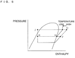
- Fig. 5 is a p-h diagram (pressure-enthalpy diagram) illustrating a state transition of a heat source side refrigerant during the cooling only operation mode.
- the vertical axis indicates the pressure
- the horizontal axis indicates enthalpy.
- a low-temperature low-pressure gas refrigerant sucked from the suction inlet of the compressor 10 is fed into an air-tight container, and the low-temperature low-pressure gas refrigerant filling the air-tight container is sucked into a compression chamber (not shown).
- a motor not shown
- the internal capacity of the compression chamber decreases.
- the refrigerant sucked into the compression chamber is compressed so as to increase the pressure and the temperature thereof.
- an opening formed in part of the compression chamber
- this state is indicated by point F in Fig. 5
- the inside of the compression chamber and the injection pipe 4c positioned outside the compressor 10 communicate with each other.
- the refrigerant compressed in the compressor 10 is condensed and liquefied in the heat source side heat exchanger 12 and is transformed into a high-pressure liquid refrigerant (indicated by point J in Fig. 5 ).
- the high-pressure liquid refrigerant then reaches the branch portion 27a via the check valve 13a.
- This high-pressure liquid refrigerant is branched at the branch portion 27a, and part of the refrigerant is decompressed into a low-temperature intermediate-pressure two-phase refrigerant in the expansion device 14b.
- the low-temperature intermediate-pressure two-phase refrigerant then flows into the injection pipe 4c via the branch pipe 4d.
- the refrigerant flowing into the injection pipe 4c flows into the compression chamber through the opening provided in the compression chamber of the compressor 10.
- the refrigerant flows into the compression chamber of the compressor 10 as a low-temperature intermediate-pressure two-phase refrigerant with a slightly reduced pressure (indicated by point K in Fig. 5 ).
- the low-temperature intermediate-pressure two-phase refrigerant (indicated by point K in Fig. 5 ) is mixed with the intermediate-pressure gas refrigerant (indicated by point F in Fig. 5 ), thereby reducing the temperature of the refrigerant (indicated by point H in Fig. 5 ).
- the discharge temperature of the refrigerant discharged from the compressor 10 is reduced (indicated by point I in Fig. 5 ).
- the discharge temperature of the compressor 10 when such an injecting operation is not performed is indicated by point G in Fig. 5 , and it is understood that the discharge temperature is reduced from point G to point I because the injecting operation has been performed.
- the opening degree of the expansion device 14b by changing the opening degree of the expansion device 14b, the pressure of a refrigerant positioned on the upstream side of the expansion device 14b is changed, thereby controlling the amount of refrigerant to be injected into the compression chamber of the compressor 10. As a result, the discharge temperature or the discharge superheat of the compressor 10 can be controlled.
- a refrigerant flowing through a flow channel from the expansion device 14b to the backflow preventing device 20 in the branch pipe 4d is an intermediate-pressure refrigerant
- a refrigerant returning from the heat medium relay unit 3 to the outdoor unit 1 via the refrigerant pipe 4 and reaching the branch portion 27b is a low-pressure refrigerant.
- the backflow preventing device 20 prevents a refrigerant flowing through the branch pipe 4d from flowing into the branch portion 27b. Due to the function of the backflow preventing device 20, the intermediate-pressure refrigerant flowing through the branch pipe 4d is prevented from being mixed with the low-pressure refrigerant flowing at the branch portion 27b.
- the backflow preventing device 20 may be a check valve.
- the backflow preventing device 20 may be a valve in which the opened/closed states can be switched, such as a solenoid valve, or a valve in which the aperture area is changeable and the opened/closed states of a flow channel can be switched, such as an electronic expansion valve.
- a refrigerant does not flow through the expansion device 14a, and thus, the opening degree of the expansion device 14a may be set as desired.
- the expansion device 14b a valve whose aperture area can be changed, such as an electronic expansion valve, is used, and the aperture area is controlled so that the discharge temperature of the compressor 10 detected by the discharged refrigerant temperature detecting device 37 will not become excessively high.
- the aperture area of the expansion device 14b may be controlled in the following manner.
- the expansion device 14b may be opened by a certain opening degree, for example, every 10 pulses.
- the opening degree may be controlled so that the discharge temperature will be a target value, for example, 100 degrees centigrade.
- a capillary tube may be used, and a refrigerant may be injected by an amount in accordance with a pressure difference.
- cooling energy of a heat source side refrigerant is transmitted to a heat medium in both of the heat exchangers 15a and 15b related to heat medium, and the cooled heat medium circulates within the pipes 5 by using the pumps 21a and 21 b.
- the heat medium pressurized in the pumps 21a and 21b flows out of the pumps 21a and 21b into the use side heat exchangers 26a and 26b via the second heat medium flow switching devise 23a and 23b, respectively. Then, the heat medium absorbs heat from indoor air in the use side heat exchangers 26a and 26b, thereby cooling the indoor space 7.
- the heat medium flows out of each of the use side heat exchangers 26a and 26b and flows into the corresponding one of heat medium flow control devices 25a and 25b.
- the flow rate of the heat medium is set to be a flow rate which is necessary to compensate for an air conditioning load required indoors, and then, the heat medium flows into the use side heat exchangers 26a and 26b.
- the heat medium flowing out of each of the heat medium flow control devices 25a and 25b passes through corresponding one of the first heat medium flow switching devices 22a and 22b, flows into the heat exchangers 15a and 15b related to heat medium, and are then sucked into the pumps 21a and 21b again.
- a heat medium flows in the direction from the second heat medium flow switching device 23 to the first heat medium flow switching device 22 via the heat medium flow control device 25.
- An air conditioning load required in the indoor space 7 can be compensated for by performing control so that the difference between the temperature detected by the first temperature sensor 31a or 31b and the temperature detected by the second temperature sensor 34 will be maintained at a target value.
- the temperature at the outlet of the heat exchanger 15 related to heat medium either of the temperature of the first temperature sensor 31a or that of the first temperature sensor 31b may be used, or the average of these temperatures may be used.
- the opening degrees of the first heat medium flow switching device 22 and the second heat medium flow switching device 23 are set to be an intermediate degree so that it is possible to secure flow channels through which a heat medium flows both to the heat exchangers 15a and 15b related to heat medium.
- Fig. 6 is a refrigerant circuit diagram illustrating the flow of a refrigerant in the heating only operation mode performed by the air-conditioning apparatus 100.
- the heating only operation mode will be discussed with reference to Fig. 6 by taking, as an example, a case in which a heating load is generated only in the use side heat exchangers 26a and 26b.
- the pipes indicated by the thick lines are pipes through which refrigerants (a heat source side refrigerant and a heat medium) flow.
- the direction in which a heat source side refrigerant flows is indicated by the solid arrows
- the direction in which a heat medium flows is indicated by the dotted arrows.
- the first refrigerant flow switching device 11 is switched so that a heat source side refrigerant discharged from the compressor 10 will flow into the heat medium relay unit 3 without passing through the heat source side heat exchanger 12.
- the pumps 21a and 21b are driven to open the heat medium flow control devices 25a and 25b and to set the heat medium flow control devices 25c and 25d in the full closed state, thereby allowing a heat medium to circulate between each of the heat exchangers 15a and 15b related to heat medium and the use side heat exchangers 26a and 26b.
- a low-temperature low-pressure refrigerant is compressed by the compressor 10 and is discharged as a high-temperature high-pressure gas refrigerant.
- the high-temperature high-pressure gas refrigerant discharged from the compressor 10 passes through the first refrigerant flow switching device 11 and the first connecting pipe 4a, passes through the check value 13b and the branch portion 27a, and flows out of the outdoor unit 1.
- the high-temperature high-pressure gas refrigerant flowing out of the outdoor unit 1 flows into the heat medium relay unit 3 via the refrigerant pipe 4.
- the high-temperature high-pressure gas refrigerant flowing into the heat medium relay unit 3 is branched, passes through the second refrigerant flow switching devices 18a and 18b, and then flows into each of the heat exchangers 15a and 15b related to heat medium.
- This high-temperature high-pressure gas refrigerant flowing into the heat exchangers 15a and 15b related to heat medium is condensed and liquefied while transferring heat to a heat medium circulating in the heat medium circuit B, and is transformed into a high-pressure liquid refrigerant.
- the liquid refrigerant flowing out of the heat exchangers 15a and 15b related to heat medium is expanded in the expansion devices 16a and 16b into an intermediate-temperature intermediate-pressure two-phase refrigerant.
- This two-phase refrigerant passes through the opening/closing device 17b, flows out of the heat medium relay unit 3, and again flows into the outdoor unit 1 via the refrigerant pipe 4.
- the refrigerant flowing into the outdoor unit 1 partially flows into the second connecting pipe 4b via the branch portion 27b and passes through the expansion device 14a. At this time, the refrigerant flow is regulated in the expansion device 14a and is transformed into a low-temperature low-pressure two-phase refrigerant. This two-phase refrigerant passes through the check valve 13c and flows into the heat source side heat exchanger 12, which serves as an evaporator.
- the refrigerant flowing into the heat source side heat exchanger 12 absorbs heat from outdoor air in the heat source side heat exchanger 12 and is transformed into a low-temperature low-pressure gas refrigerant.
- the low-temperature low-pressure gas refrigerant flowing out of the heat source side heat exchanger 12 is again sucked into the compressor 10 via the first refrigerant flow switching device 11 and the accumulator 19.
- the opening degree of the expansion device 16a is controlled so that subcooling (degree of subcooling) obtained as a difference between the saturation temperature converted from the pressure detected by the pressure sensor 36 and the temperature detected by the third temperature sensor 35b will become constant.
- the opening degree of the expansion device 16b is controlled so that subcooling (degree of subcooling) obtained as a difference between the saturation temperature converted from the pressure detected by the pressure sensor 36 and the temperature detected by the third temperature sensor 35d will become constant.
- the opening/closing device 17a is closed, and the opening/closing device 17b is opened. If the temperature of the intermediate position of the heat exchanger 15 related to heat medium can be measured, it may be used instead of the pressure detected by the pressure sensor 36. Then, the system can be constructed at low cost.
- Fig. 7 is a p-h diagram (pressure-enthalpy diagram) illustrating a state transition of a heat source side refrigerant during the heating only operation mode.
- the vertical axis indicates the pressure
- the horizontal axis indicates enthalpy.
- a low-temperature low-pressure gas refrigerant sucked from the suction inlet of the compressor 10 is fed into an air-tight container, and the low-temperature low-pressure gas refrigerant filling the air-tight container is sucked into a compression chamber (not shown).
- a motor not shown
- the internal capacity of the compression chamber decreases.
- the refrigerant sucked into the compression chamber is compressed so as to increase the pressure and the temperature thereof.
- an opening formed in part of the compression chamber
- this state is indicated by point F in Fig. 7
- the inside of the compression chamber and the injection pipe 4c positioned outside the compressor 10 communicate with each other.
- the refrigerant returning from the heat medium relay unit 3 to the outdoor unit 1 via the refrigerant pipe 4 partially flows into the expansion device 14a via the branch portion 27b. Due to the working of the expansion device 14a, the pressure of the refrigerant positioned on the upstream side of the expansion device 14a is set in the intermediate pressure state (indicated by point J in Fig. 7 ). Part of the two-phase refrigerant which is set in the intermediate pressure state by the expansion device 14a is diverted at the branch portion 27b and flows into the branch pipe 4d. This refrigerant then flows into the injection pipe 4c via the backflow preventing device 20 and flows into the compression chamber through the opening provided in the compression chamber of the compressor 10.
- the refrigerant flows into the compression chamber of the compressor 10 as a low-temperature intermediate-pressure two-phase refrigerant with a slightly reduced pressure (indicated by point K in Fig. 7 ).
- the low-temperature intermediate-pressure two-phase refrigerant (indicated by point K in Fig. 7 ) is mixed with the intermediate-pressure gas refrigerant (indicated by point F in Fig. 7 ), thereby reducing the temperature of the refrigerant (indicated by point H in Fig. 7 ).
- the discharge temperature of the refrigerant discharged from the compressor 10 is reduced (indicated by point I in Fig. 7 ).
- the discharge temperature of the compressor 10 at the time at which such an injecting operation is not performed is indicated by point G in Fig. 7 , and it is understood that the discharge temperature is reduced from point G to point I because the injecting operation has been performed.
- a refrigerant in a two-phase state flows into the branch portion 27b.
- the branch portion 27b is configured such that the refrigerant is branched at the branch portion 27b in the state in which it flows from the bottom to the top side in the vertical direction. With this structure, the two-phase refrigerant is uniformly distributed.
- the opening degree of the expansion device 14a by changing the opening degree of the expansion device 14a, the amount of refrigerant to be injected into the compression chamber of the compressor 10 is adjusted. As a result, the discharge temperature or the discharge superheat of the compressor 10 can be controlled.
- the expansion device 14b is in the full closed state, or the opening degree of the expansion device 14b is small in such a degree as not to allow a refrigerant to flow therethrough. In this manner, a high-pressure refrigerant flowing through the branch portion 27a can be prevented from being mixed with an intermediate-pressure refrigerant passing through the backflow preventing device 20.
- the expansion device 14a a device whose aperture area can be changed, such as an electronic expansion valve, is desirably used. If an electronic expansion valve is used, control can be performed so that the intermediate pressure on the upstream side of the expansion device 14a may be set to a desired pressure. For example, if control is performed so that the intermediate pressure detected by the intermediate-pressure detecting device 32 may be set to a constant value, the expansion device 14a can stably control the discharge temperature.
- the expansion device 14a is not restricted to an electronic expansion valve, and any device may be used as long as it can perform control so that the discharge temperature may be set to a target value.
- the expansion device 14a for example, on/off valves, such as small solenoid valves, are combined so as to select a plurality of aperture areas.
- a capillary tube may be used so as to form the intermediate pressure in accordance with a pressure drop occurring in a refrigerant.
- the intermediate-pressure sensor 32 may be a pressure sensor.
- a temperature sensor may be used, and the intermediate pressure may be calculated.
- heating energy of a heat source side refrigerant is transmitted to a heat medium in both of the heat exchangers 15a and 15b related to heat medium, and the heated heat medium circulates within the pipes 5 by using the pumps 21a and 21b.
- the heat medium pressurized in each of the pumps 21a and 21b flows out of the respective one of the pumps 21a and 21b into the use side heat exchangers 26a and 26b via the corresponding one of the second heat medium flow switching devise 23a and 23b. Then, the heat medium transfers heat to indoor air in the use side heat exchangers 26a and 26b, thereby heating the indoor space 7.
- the heat medium flows out of each of the use side heat exchangers 26a and 26b and flows into the corresponding one of the heat medium flow control devices 25a and 25b.
- the flow rate of the heat medium is set to be a flow rate which is necessary to compensate for an air conditioning load required indoors, and then, the heat medium flows into the use side heat exchangers 26a and 26b.
- the heat medium flowing out of each of the heat medium flow control devices 25a and 25b passes through the corresponding one of the first heat medium flow switching devices 22a and 22b, flows into the heat exchangers 15a and 15b related to heat medium, and is then sucked into the pumps 21a and 21b again.
- a heat medium flows in the direction from the second heat medium flow switching device 23 to the first heat medium flow switching device 22 via the heat medium flow control device 25.
- An air conditioning load required in the indoor space 7 can be satisfied by performing control so that the difference between the temperature detected by the first temperature sensor 31a or 31b and the temperature detected by the second temperature sensor 34 will be maintained at a target value.
- the temperature at the outlet of the heat exchanger 15 related to heat medium either of the temperature of the first temperature sensor 31a or that of the first temperature sensor 31b may be used, or the average of these temperatures may be used.
- the opening degrees of the first heat medium flow switching device 22 and the second heat medium flow switching device 23 are set to be an intermediate opening degree so that it is possible to secure flow channels through which a heat medium flows both to the heat exchangers 15a and 15b related to heat medium.
- the use side heat exchanger 26a should be controlled by the difference between the temperature at the inlet and that at the outlet.
- the temperature of a heat medium at the inlet side of the use side heat exchanger 26 is substantially the same as the temperature detected by the first temperature sensor 31b. Accordingly, by the use of the first temperature sensor 31b, the number of temperature sensors can be decreased, and the system can be constructed at low cost.
- the opening degree of the heat medium flow control device 25 is controlled depending on whether or not there is a heating load in the use side heat exchanger 26.
- Fig. 8 is a refrigerant circuit diagram illustrating the flow of a refrigerant in the cooling main operation mode performed by the air-conditioning apparatus 100.
- the cooling main operation mode will be discussed with reference to Fig. 8 by taking, as an example, a case in which a cooling load is generated in the use side heat exchanger 26a and a heating load is generated in the use side heat exchanger 26b.
- the pipes indicated by the thick lines are pipes through which refrigerants (a heat source side refrigerant and a heat medium) circulate.
- the direction in which a heat source side refrigerant flows is indicated by the solid arrows
- the direction in which a heat medium flows is indicated by the dotted arrows.
- the first refrigerant flow switching device 11 is switched so that a heat source side refrigerant discharged from the compressor 10 will flow into the heat source side heat exchanger 12.
- the pumps 21a and 21b are driven to open the heat medium flow control devices 25a and 25b and to set the heat medium flow control devices 25c and 25d in the full closed state, thereby allowing a heat medium to circulate between the heat exchanger 15a related to heat medium and the use side heat exchanger 26a and between the heat exchanger 15b related to heat medium and the use side heat exchanger 26b.
- a low-temperature low-pressure refrigerant is compressed by the compressor 10 and is discharged as a high-temperature high-pressure gas refrigerant.
- the high-temperature high-pressure gas refrigerant discharged from the compressor 10 flows into the heat source side heat exchanger 12 via the first refrigerant flow switching device 11.
- the heat source side heat exchanger 12 the high-temperature high-pressure gas refrigerant is condensed into a two-phase refrigerant while transferring heat to outdoor air.
- the two-phase refrigerant flowing out of the heat source side heat exchanger 12 passes through the check valve 13a and partially flows out of the outdoor unit 1 via the branch portion 27a and flows into the heat medium relay unit 3 via the refrigerant pipe 4.
- the two-phase refrigerant flowing into the heat medium relay unit 3 passes through the second refrigerant flow switching device 18b and flows into the heat exchanger 15b related to heat medium, which serves as a condenser.
- the two-phase refrigerant flowing into the heat exchanger 15b related to heat medium is condensed and liquefied while transferring heat to a heat medium circulating in the heat medium circuit B, and is transformed into a liquid refrigerant.
- the liquid refrigerant flowing out of the heat exchanger 15b related to heat medium is expanded into a low-pressure two-phase refrigerant in the expansion device 16b.
- This low-pressure two-phase refrigerant flows into the heat exchanger 15a related to heat medium, which serves as an evaporator, via the expansion device 16a.
- the low-pressure two-phase refrigerant flowing into the heat exchanger 15a related to heat medium absorbs heat from a heat medium circulating in the heat medium circuit B and is thereby transformed into a low-pressure gas refrigerant while cooling the heat medium.
- This gas refrigerant flows out of the heat exchanger 15a related to heat medium, flows out of the heat medium relay unit 3 via the second refrigerant flow switching device 18a, and again flows into the outdoor unit 1 via the refrigerant pipe 4.
- the refrigerant flowing into the outdoor unit 1 passes through the check value 13d via the branch portion 27b and is again sucked into the compressor 10 via the first refrigerant flow switching device 11 and the accumulator 19.
- the opening degree (aperture area) of the expansion device 16b is controlled so that the superheat obtained as a difference between the temperature detected by the third temperature sensor 35a and the temperature detected by the third temperature sensor 35b will become constant.
- the expansion device 16a is set in the full opened state.
- the opening/closing device 17a is closed, and the opening/closing device 17b is closed.
- the opening degree of the expansion device 16b may be controlled so that the subcool obtained as a difference between the saturation temperature converted from the pressure detected by the pressure sensor 36 and the temperature detected by the third temperature sensor 35d may be constant.
- the expansion device 16b may be set in the full opened state, and the superheat or subcool may be controlled by using the expansion device 16a.
- Fig. 9 is a p-h diagram (pressure-enthalpy diagram) illustrating a state transition of a heat source side refrigerant during the cooling main operation mode.
- the vertical axis indicates the pressure
- the horizontal axis indicates enthalpy.
- a low-temperature low-pressure gas refrigerant sucked from the suction inlet of the compressor 10 is fed into an air-tight container, and the low-temperature low-pressure gas refrigerant filling the air-tight container is sucked into a compression chamber (not shown).
- a motor not shown
- the internal capacity of the compression chamber decreases.
- the refrigerant sucked into the compression chamber is compressed so as to increase the pressure and the temperature.
- an opening formed in part of the compression chamber
- this state is indicated by point F in Fig. 9
- the inside of the compression chamber and the injection pipe 4c positioned outside the compressor 10 communicate with each other.
- the refrigerant compressed in the compressor 10 is condensed into a high-pressure two-phase refrigerant in the heat source side heat exchanger 12 (indicated by point J in Fig. 9 ).
- the high-pressure two-phase refrigerant then reaches the branch portion 27a via the check valve 13a.
- This high-pressure two-phase refrigerant is branched at the branch portion 27a, and part of the refrigerant is decompressed into a low-temperature intermediate-pressure two-phase refrigerant in the expansion device 14b.
- the low-temperature intermediate-pressure two-phase refrigerant then flows into the injection pipe 4c via the branch pipe 4d.
- the refrigerant flowing into the injection pipe 4c flows into the compression chamber through the opening formed in the compression chamber of the compressor 10.
- the refrigerant flows into the compression chamber of the compressor 10 as a low-temperature intermediate-pressure two-phase refrigerant with a slightly reduced pressure (indicated by point K in Fig. 9 ).
- the low-temperature intermediate-pressure two-phase refrigerant (indicated by point K in Fig. 9 ) is mixed with the intermediate-pressure gas refrigerant (indicated by point F in Fig. 9 ), thereby reducing the temperature of the refrigerant (indicated by point H in Fig. 9 ).
- the discharge temperature of the refrigerant discharged from the compressor 10 is reduced (indicated by point I in Fig. 9 ).
- the discharge temperature of the compressor 10 when such an injecting operation is not performed is indicated by point G in Fig. 9 , and it is understood that the discharge temperature is reduced from point G to point I because the injecting operation has been performed.
- a refrigerant in a two-phase state flows into the branch portion 27a.
- the branch portion 27a is configured such that the refrigerant is branched at the branch portion 27a in the state in which it flows from the bottom to the top side in the vertical direction. With this structure, the two-phase refrigerant is uniformly distributed.
- the opening degree of the expansion device 14b As in the cooling only operation mode, in the cooling main operation mode, by changing the opening degree of the expansion device 14b, the pressure of a refrigerant positioned on the upstream side of the expansion device 14b is changed, thereby controlling the amount of refrigerant to be injected into the compression chamber of the compressor 10. As a result, the discharge temperature or the discharge superheat of the compressor 10 can be controlled. As in the cooling only operation mode, due to the working of the backflow preventing device 20, the intermediate-pressure refrigerant flowing through the branch pipe 4d is prevented from being mixed with the low-pressure refrigerant flowing at the branch portion 27b. Moreover, since a refrigerant does not flow through the expansion device 14a, the opening degree of the expansion device 14a may be set to a desired opening degree.
- heating energy of a heat source side refrigerant is transmitted to a heat medium in the heat exchanger 15b related to heat medium, and the heated heat medium circulates within the pipes 5 by using the pump 21b.
- cooling energy of a heat source side refrigerant is transmitted to a heat medium in the heat exchanger 15a related to heat medium, and the cooled heat medium circulates within the pipes 5 by using the pump 21a.
- the heat medium pressurized in each of the pumps 21a and 21b flows into the use side heat exchangers 26a and 26b via the corresponding one of the second heat medium flow switching devise 23a and 23b.
- the heat medium transfers heat to indoor air, thereby heating the indoor space 7.
- the heat medium absorbs heat from indoor air, thereby cooling the indoor space 7.
- the flow rate of the heat medium is set to be a flow rate which is necessary to compensate for an air conditioning load required indoors, and then, the heat medium flows into each of the use side heat exchangers 26a and 26b.
- the heat medium with a slightly reduced temperature after passing through the use side heat exchanger 26b passes through the heat medium flow control device 25b and the first heat medium flow switching device 22b, flows into the heat exchanger 15b related to heat medium, and is then sucked into the pump 21b again.
- the heat medium with a slightly increased temperature after passing through the use side heat exchanger 26a passes through the heat medium flow control device 25a and the first heat medium flow switching device 22a, flows into the heat exchanger 15a related to heat medium, and is then sucked into the pump 21a again.
- a heated heat medium and a cooled heat medium are respectively fed to a use side heat exchanger 26 with a heating load and a use side heat exchanger 26 with a cooling load without being mixed with each other.
- a heat medium flows in the direction from the second heat medium flow switching devices 23 to the first heat medium flow switching devices 22 via the heat medium flow control devices 25.
- An air conditioning load required in the indoor space 7 can be compensated for by performing control so that, for the heating side, the difference between the temperature detected by the first temperature sensor 31b and the temperature detected by the second temperature sensor 34 will be maintained at a target value, and so that, for the cooling side, the difference between the temperature detected by the first temperature sensor 31a and the temperature detected by the second temperature sensor 34 will be maintained at a target value.
- the opening degree of the heat medium flow control device 25 is controlled depending on whether or not there is a heating load in the use side heat exchanger 26.
- Fig. 10 is a refrigerant circuit diagram illustrating the flow of a refrigerant in the heating main operation mode performed by the air-conditioning apparatus 100.
- the heating main operation mode will be discussed with reference to Fig. 10 by taking, as an example, a case in which a heating load is generated in the use side heat exchanger 26a and a cooling load is generated in the use side heat exchanger 26b.
- the pipes indicated by the thick lines are pipes through which refrigerants (a heat source side refrigerant and a heat medium) circulate.
- the direction in which a heat source side refrigerant flows is indicated by the solid arrows
- the direction in which a heat medium flows is indicated by the dotted arrows.
- the first refrigerant flow switching device 11 is switched so that a heat source side refrigerant discharged from the compressor 10 will flow into the heat medium relay unit 3 without passing through the heat source side heat exchanger 12.
- the pumps 21a and 21b are driven to open the heat medium flow control devices 25a and 25b and to set the heat medium flow control devices 25c and 25d in the full closed state, thereby allowing a heat medium to circulate between the heat exchanger 15a related to heat medium and the use side heat exchanger 26b and between the heat exchanger 15b related to heat medium and the use side heat exchanger 26a.
- a low-temperature low-pressure refrigerant is compressed by the compressor 10 and is discharged as a high-temperature high-pressure gas refrigerant.
- the high-temperature high-pressure gas refrigerant discharged from the compressor 10 passes through the first refrigerant flow switching device 11 and the first connecting pipe 4a, passes through the check value 13b, and flows out of the outdoor unit 1 via the branch portion 27a.
- the high-temperature high-pressure gas refrigerant flowing out of the outdoor unit 1 flows into the heat medium relay unit 3 via the refrigerant pipe 4.
- the high-temperature high-pressure gas refrigerant flowing into the heat medium relay unit 3 passes through the second refrigerant flow switching device 18b and flows into the heat exchanger 15b related to heat medium, which serves as a condenser.
- the gas refrigerant flowing into the heat exchanger 15b related to heat medium is condensed and liquefied while transferring heat to a heat medium circulating in the heat medium circuit B, and is transformed into a liquid refrigerant.
- the liquid refrigerant flowing out of the heat exchanger 15b related to heat medium is expanded to an intermediate-pressure two-phase refrigerant in the expansion device 16b.
- This intermediate-pressure two-phase refrigerant flows into the heat exchanger 15a related to heat medium, which serves as an evaporator, via the expansion device 16a.
- the intermediate-pressure two-phase refrigerant flowing into the heat exchanger 15a related to heat medium absorbs heat from a heat medium circulating in the heat medium circuit B so as to evaporate, thereby cooling the heat medium.
- This intermediate-pressure two-phase refrigerant flows out of the heat exchanger 15a related to heat medium, flows out of the heat medium relay unit 3 via the second refrigerant flow switching device 18a, and again flows into the outdoor unit 1 via the ref
- the refrigerant flowing into the outdoor unit 1 partially flows into the second connecting pipe 4b via the branch portion 27b and passes through the expansion device 14a.
- the refrigerant flow is regulated in the expansion device 14a and is transformed into a low-temperature low-pressure two-phase refrigerant.
- This two-phase refrigerant passes through the check valve 13c and flows into the heat source side heat exchanger 12, which serves as an evaporator.
- the refrigerant flowing into the heat source side heat exchanger 12 absorbs heat from outdoor air in the heat source side heat exchanger 12 and is transformed into a low-temperature low-pressure gas refrigerant.
- the low-temperature low-pressure gas refrigerant flowing out of the heat source side heat exchanger 12 is again sucked into the compressor 10 via the first refrigerant flow switching device 11 and the accumulator 19.
- the opening degree of the expansion device 16b is controlled so that subcooling obtained as a difference between the saturation temperature converted from the pressure detected by the pressure sensor 36 and the temperature detected by the third temperature sensor 35b will become constant.
- the expansion device 16a is set in the full opened state.
- the opening/closing device 17a is closed, and the opening/closing device 17b is closed.
- the expansion device 16b may be set in the full opened state, and subcooling may be controlled by using the expansion device 16a.
- Fig. 11 is a p-h diagram (pressure-enthalpy diagram) illustrating a state transition of a heat source side refrigerant during the heating main operation mode.
- the vertical axis indicates the pressure
- the horizontal axis indicates enthalpy.
- a low-temperature low-pressure gas refrigerant sucked from the suction inlet of the compressor 10 is fed into an air-tight container, and the low-temperature low-pressure gas refrigerant filling the air-tight container is sucked into a compression chamber (not shown).
- a motor not shown
- the internal capacity of the compression chamber decreases.
- the refrigerant sucked into the compression chamber is compressed so as to increase the pressure and the temperature thereof.
- an opening formed in part of the compression chamber
- this state is indicated by point F in Fig. 11
- the inside of the compression chamber and the injection pipe 4c positioned outside the compressor 10 communicate with each other.
- the refrigerant returning from the heat medium relay unit 3 to the outdoor unit 1 via the refrigerant pipe 4 partially flows into the expansion device 14a via the branch portion 27b. Due to the function of the expansion device 14a, the pressure of the refrigerant positioned on the working side of the expansion device 14a is set in the intermediate pressure state (indicated by point J in Fig. 11 ). Part of the two-phase refrigerant which is set in the intermediate pressure state by the expansion device 14a is diverted at the branch portion 27b and flows into the branch pipe 4d. This refrigerant then flows into the injection pipe 4c via the backflow preventing device 20 and flows into the compression chamber through the opening provided in the compression chamber of the compressor 10.
- the refrigerant flows into the compression chamber of the compressor 10 as a low-temperature intermediate-pressure two-phase refrigerant with a slightly reduced pressure (indicated by point K in Fig. 11 ).
- the low-temperature intermediate-pressure two-phase refrigerant (indicated by point K in Fig. 11 ) is mixed with the intermediate-pressure gas refrigerant (indicated by point F in Fig. 11 ), thereby reducing the temperature of the refrigerant (indicated by point H in Fig. 11 ).
- the discharge temperature of the refrigerant discharged from the compressor 10 is reduced (indicated by point I in Fig. 11 ).
- the discharge temperature of the compressor 10 when such an injecting operation is not performed is indicated by point G in Fig. 11 , and it is understood that the discharge temperature is reduced from point G to point I because the injecting operation has been performed.
- the branch portion 27b is configured such that a refrigerant is branched at the branch portion 27b in the state in which it flows from the bottom to the top side in the vertical direction.
- the heating main operation mode as in the heating only operation mode, by changing the opening degree of the expansion device 14a, the amount of refrigerant to be injected into the compression chamber of the compressor 10 is controlled. As a result, the discharge temperature or the discharge superheat of the compressor 10 can be controlled.
- the expansion device 14b is in the full closed state, or the opening degree of the expansion device 14b is small to such a degree as not to allow a refrigerant to flow therethrough. In this manner, a high-pressure refrigerant flowing through the branch portion 27a can be prevented from being mixed with an intermediate-pressure refrigerant passing through the backflow preventing device 20.
- the expansion device 14a may be controlled, as discussed with reference to the heating only operation mode.
- the intermediate-pressure detecting device 32 may be configured and the expansion device 14b may be configured and controlled, as discussed with reference to the heating only operation mode.
- heating energy of a heat source side refrigerant is transmitted to a heat medium in the heat exchanger 15b related to heat medium, and the heated heat medium is circulated within the pipes 5 by the pump 21b.
- cooling energy of a heat source side refrigerant is transmitted to a heat medium in the heat exchanger 15a related to heat medium, and the cooled heat medium circulates within the pipes 5 by using the pump 21a.
- the heat medium pressurized in each of the pumps 21a and 21b flows into the use side heat exchangers 26b and 26a via the corresponding one of the second heat medium flow switching devise 23b and 23a.
- the heat medium absorbs heat from indoor air, thereby cooling the indoor space 7.
- the heat medium transfers heat to indoor air, thereby heating the indoor space 7.
- the flow rate of the heat medium is set to be a flow rate which is necessary to satisfy an air conditioning load required indoors, and then, the heat medium flows into the use side heat exchangers 26a and 26b.
- the heat medium with a slightly increased temperature after passing through the use side heat exchanger 26b passes through the heat medium flow control device 25b and the first heat medium flow switching devices 22b, flows into the heat exchanger 15a related to heat medium, and is then sucked into the pump 21a again.
- the heat medium with a slightly reduced temperature after passing through the use side heat exchanger 26a passes through the heat medium flow control device 25a and the first heat medium flow switching devices 22a, flows into the heat exchanger 15b related to heat medium, and is then sucked into the pump 21b again.
- a heated heat medium and a cooled heat medium are respectively fed to a use side heat exchanger 26 with a heating load and a use side heat exchanger 26 with a cooling load without being mixed with each other.
- a heat medium flows in the direction from the second heat medium flow switching devices 23 to the first heat medium flow switching devices 22 via the heat medium flow control devices 25.
- An air conditioning load required in the indoor space 7 can be compensated for by performing control so that, for the heating side, the difference between the temperature detected by the first temperature sensor 31b and the temperature detected by the second temperature sensor 34 will be maintained at a target value, and so that, for the cooling side, the difference between the temperature detected by the first temperature sensor 31a and the temperature detected by the second temperature sensor 34 will be maintained at a target value.
- the opening degree of the heat medium flow control device 25 is controlled depending on whether or not there is a heating load in the use side heat exchanger 26.
- the injecting operations for injecting a refrigerant to the compression chamber of the compressor 10 in the individual operation modes are performed as described above. Accordingly, a refrigerant in a two-phase state flows into the expansion device 14a during the heating only operation mode and the heating main operation mode. A liquid refrigerant flows into the expansion device 14b during the cooling only operation mode, and a refrigerant in a two-phase state flows into the expansion device 14b during the cooling main operation mode.
- an electronic expansion valve as the expansion device, if a two-phase refrigerant flows into the expansion device in the state in which a gas refrigerant and a liquid refrigerant are separated, a state in which a gas flows and a state in which a liquid flows are separately generated at an expanding portion. As a result, the pressure at the outlet of the expansion device may become unstable. This is more likely to happen particularly when the quality of a refrigerant is small because the separation of the refrigerant is accelerated. Accordingly, as the expansion device 14a and/or the expansion device 14b, an expansion device having a structure shown in Fig. 12 may be used. Then, even if a two-phase refrigerant flows into the expansion device, control can be performed stably.
- Fig. 12 schematically illustrates an example of the suitable configuration of the expansion device 14a and/or the expansion device 14b (hereinafter collectively referred to as the "expansion device 14").
- the expansion device 14 includes an inlet pipe 41, an outlet pipe 42, an expanding portion 43, a valve body 44, a motor 45, and an agitator 46.
- the agitator 46 is installed within the inlet pipe 41.
- a two-phase refrigerant flowing out of the inlet pipe 41 reaches the agitator 46, and due to the working of the agitator 46, a gas refrigerant and a liquid refrigerant are agitated and mixed with each other substantially uniformly.
- the two-phase refrigerant in which the gas refrigerant and the liquid refrigerant are mixed with each other substantially uniformly due to the working of the agitator 46 reaches the expanding portion 43.
- the flow of the two-phase refrigerant is then regulated by the valve body 44 in the expanding portion 43 and is thereby decompressed, and then flows out of the outlet pipe 42.
- the position of the valve body 44 is controlled by the motor 45, and thus, the amount by which the refrigerant flow is regulated in the expanding portion 43 is controlled.
- the agitator 46 any type may be used as long as it can produce a state in which a gas refrigerant and a liquid refrigerant are mixed with each other substantially uniformly.
- the agitator 46 can be implemented by using metal foam.
- the metal foam is a metallic porous body having a three-dimensional mesh structure, like a resin foam body, such as a sponge, and has a largest porosity ratio (void ratio) (80 to 97%) among metallic porous bodies. If a two-phase refrigerant is distributed through this metal foam, the gas within the refrigerant becomes finer and is agitated, thereby being effectively mixed with a liquid uniformly, by the influence of the three-dimensional mesh structure.
- the air-conditioning apparatus 100 has several operation modes.
- a heat source side refrigerant flows through the pipes 4 which connect the outdoor unit 1 and the heat medium relay unit 3.
- a heat medium such as water or an antifreeze, flows through the pipes 5 which connect the heat medium relay unit 3 and the indoor units 2.
- the pressure sensor 36b may be installed in the flow channel between the heat exchanger 15b related to heat medium and the expansion device 16b, in which case, the calculation precision is not considerably decreased.
- the pressure sensor 36a may be installed in the flow channel between the heat exchanger 15a related to heat medium and the second refrigerant flow switching device 18a.
- the opening degrees of the associated first and second heat medium flow switching devices 22 and 23 are set to be an intermediate opening degree, thereby allowing a heat medium to flow both through the heat exchangers 15a and 15b related to heat medium.
- both of the heat exchangers 15a and 15b related to heat medium can be used for the heating operation or the cooling operation, and thus, the heat transfer area is increased, thereby implementing a high-efficiency heating operation or cooling operation.
- any type of device that can switch the flow channel may be used.
- devices that can switch a three-way passage such as three-port valves, or a combination of two devices that open and close a two-way passage, such as on/off valves, may be used.
- a device that can change the flow rate of a three-way passage such as a stepping motor driving type mixing valve, or a combination of two devices that can change the flow rate of a two-way passage, such as electronic expansion valves, may be used. In this case, the occurrence of water hammer caused by the sudden opening or closing of a flow channel may be prevented.
- the heat medium flow control device 25 may be a control valve having a three-way passage, and may be installed together with a bypass pipe that bypasses the use side heat exchanger 26.
- a stepping motor driving type device that can control the flow rate of a refrigerant flowing through a flow channel may be used, in which case, a two-port valve or a three-port valve with one port closed may be used.
- a device that opens and closes a two-way passage, such as an on/off valve may be used, in which case, the heat medium flow control device 25 may control an average flow rate by repeating ON/OFF operations.
- a four-way valve may be used as the second refrigerant flow switching device 18.
- the second refrigerant flow switching device 18 is not restricted to a four-way valve. Instead, a plurality of two-way passage switching valves or three-way passage switching valves may be used, and may be configured such that a refrigerant flows therethrough similarly to the case in which a four-way valve is used.
- a heat medium for example, brine (antifreeze) or water, a mixed solution of brine and water, a mixed solution of water and an additive having a high anticorrosive effect, and so on, may be used. Accordingly, in the air-conditioning apparatus 100, since a heat medium having a high level of safety is used, even if such a heat medium leaks to the indoor space 7 via the indoor unit 2, a contribution to the enhancement of safety can be implemented.
- Embodiment 1 a case in which the accumulator 19 is included in the air-conditioning apparatus 100 has been discussed by way of example. However, the provision of the accumulator 19 may be omitted.
- an air-sending device is fixed to the heat source side heat exchanger 12 and the use side heat exchangers 26a through 26d, thereby accelerating condensation or evaporation by sending air.
- the heat source side heat exchanger 12 and the use side heat exchangers 26a through 26d are not restricted to this type.
- a panel heater utilizing radiation may be used, and as the heat source side heat exchanger 12, a water-cooled type device which can transfer heat by using water or an antifreeze may be used. Any type of device may be used as long as it is configured such that it can transfer or receive heat.
- Embodiment 1 a case in which four use side heat exchangers 26a through 26d are provided has been discussed by way of example. However, any number of use side heat exchangers 26 may be connected. Additionally, a case in which two heat exchangers 15a and 15b related to heat medium are provided has been discussed by way of example. However, the number of heat exchangers 15 related to heat medium is not restricted to two, and any number of heat exchangers 15 related to heat medium may be installed as long as they are configured such that they can cool and/or heat a heat medium. Moreover, the number of pumps 21a and the number of pumps 21b is not restricted to one, and a plurality of small-capacity pumps may be connected in parallel with each other.
- Embodiment 1 The defrosting operation in Embodiment 1 will be discussed below with reference to Fig. 13 .
- Fig. 13 is a refrigerant circuit diagram illustrating the flow of a refrigerant in the defrosting operation mode of the air-conditioning apparatus according to Embodiment 1 of the present invention.
- a refrigerant is compressed and heated by the compressor 10 and is discharged from the compressor 10.
- the refrigerant then flows into the heat source side heat exchanger 12 via the first refrigerant flow switching device 11. Then, the refrigerant transfers heat in the heat source side heat exchanger 12 and defrosts a portion around the heat source side heat exchanger 12.
- the refrigerant flowing out of the heat source side heat exchanger 12 passes through the check valve 13a, reaches the branch portion 27a, and is branched at the branch portion 27a.
- the refrigerant diverted at the branch portion 27a in one direction flows out of the outdoor unit 1 and flows into the heat medium relay unit 3 via the refrigerant pipe 4.
- the refrigerant flowing into the heat medium relay unit 3 flows out of the heat medium relay unit 3 via the opening/closing devices 17a and 17b which are in the opened state, and again flows into the outdoor unit 1 via the refrigerant pipe 4.
- the refrigerant flowing into the outdoor unit 1 passes through the check valve 13d via the branch portion 27b and is again sucked into the compressor 10 via the first refrigerant flow switching device 11 and the accumulator 19.
- the expansion devices 16a and 16b are in the full closed state, or the opening degree of the expansion devices 16a and 16b is small to such a degree as not to allow a refrigerant to flow through the heat exchangers 15a and 15b related to heat medium, respectively.
- the refrigerant diverted at the branch portion 27a in the other direction flows into the branch pipe 4d and is injected into the compression chamber of the compressor 10 via the expansion device 14b which is in the full opened state and the injection pipe 4c.
- the refrigerant then joins the refrigerant (which has been diverted at the branch portion 27a in the other direction) sucked into the compressor 10 via the accumulator 19.
- the pump 21b is operated so as to cause a heat medium to circulate in the use side heat exchangers 26 which require heating (use side heat exchangers 26a and 26b). With this operation, even during the defrosting operation, a heating operation can continue by using heating energy stored in a heat medium.
- the pump 21a may also be operated. Alternatively, during the defrosting operation, the pumps 21a and 21b may be stopped, thereby discontinuing the heating operation.
- Fig. 14 illustrates a configuration of an air-conditioning apparatus 100A according to Embodiment 2.
- expansion devices 14a, 14b, and 14c are provided in the outdoor unit 1. That is, in Embodiment 1, a case in which the backflow preventing device 20 is provided has been discussed by way of example.
- the expansion device 14c is moved to the position at which the backflow preventing device 20 is disposed in Embodiment 1, and the expansion device 14a is provided at the position at which the expansion device 14a is disposed in Embodiment 1.
- the expansion devices 14c and 14b devices that can sequentially change the opening degree (aperture area), such as electronic expansion valves, are used.
- a fixed expansion valve such as a capillary tube, or a valve with an expanding portion having a fixed aperture area, such as an on/off valve, for example, a solenoid valve having a small aperture area when it is opened, may be used.
- Basic operation modes are a cooling only operation mode, a heating only operation mode, a cooling main operation mode, and a heating main operation mode, which are similar to those of Embodiment 1. A description of detailed operations will be omitted here.
- a high-pressure liquid refrigerant is branched at the branch portion 27a, and by controlling the opening degree of the expansion device 14b, the flow rate of a refrigerant to be injected into the compression chamber of the compressor 10 via the branch pipe 4d and the injection pipe 4c is adjusted, thereby controlling the discharge temperature of the compressor 10.
- the expansion device 14c is set in the full closed state or the opening degree is set to be small to such a degree as not to allow a refrigerant to flow therethrough.
- the opening degree of the expansion device 14c by controlling the opening degree of the expansion device 14c, the flow rate of a refrigerant to be injected into the compression chamber of the compressor 10 via the branch pipe 4d and the injection pipe 4c is adjusted. As a result, the flow rate of a refrigerant to flow into the expansion device 14a is also changed, and thus, the pressure of the refrigerant positioned on the upstream side of the expansion device 14a is changed. Accordingly, both of the intermediate pressure and the discharge temperature can be controlled. In this case, the expansion device 14b is set in the full closed state or the opening degree is set to be small to such a degree as not to allow a refrigerant to flow therethrough.
- a high-pressure two-phase refrigerant is branched at the branch portion 27a, and by controlling the opening degree of the expansion device 14b, the flow rate of a refrigerant to be injected into the compression chamber of the compressor 10 via the branch pipe 4d and the injection pipe 4c is adjusted, thereby controlling the discharge temperature of the compressor 10.
- the expansion device 14c is set in the full closed state or the opening degree is set to be small to such a degree as not to allow a refrigerant to flow therethrough.
- the opening degree of the expansion device 14c by controlling the opening degree of the expansion device 14c, the flow rate of a refrigerant to be injected into the compression chamber of the compressor 10 via the branch pipe 4d and the injection pipe 4c is adjusted. As a result, the flow rate of a refrigerant to flow into the expansion device 14a is also changed, and thus, the pressure of the refrigerant positioned on the upstream side of the expansion device 14a is changed. Accordingly, both of the intermediate pressure and the discharge temperature can be controlled. In this case, the expansion device 14b is set in the full closed state or the opening degree is set to be small to such a degree as not to allow a refrigerant to flow therethrough.
- the expansion device 14b controls the expansion device 14b and controls the expansion device 14c.
- an intermediate-pressure refrigerant is branched and is injected.
- the discharge temperature is controlled in this manner.
- the expansion device to be controlled is different depending on whether the heat source side heat exchanger 12 serves as a condenser or an evaporator, and by controlling one of the expansion devices, an amount of refrigerant to be injected is controlled.
- the expansion device 14a a device with an expanding portion having a fixed aperture area, such as a capillary tube, is used, has been discussed. With this configuration, a system can be configured at low cost. However, as the expansion device 14a, a device that can sequentially change the opening degree (aperture area), such as an electronic expansion valve, may be used without any problem, in which case, the aperture area similar to that described above can be realized. Additionally, as the expansion devices 14c and 14b, devices that can switch the aperture area in a stepwise manner may be used. This can be implemented by, for example, using and switching a plurality of capillary tubes.
- Embodiment 1 and Embodiment 2 the following system has been discussed by way of example.
- the compressor 10, the first refrigerant flow switching device 11, the heat source side heat exchanger 12, the expansion devices 14a and 14b, the opening/closing device 17, and the backflow preventing device 20 (the expansion device 14a in Embodiment 2) are stored in the outdoor unit 1.
- the use side heat exchanger 26 is stored in the indoor unit 2, and the heat exchanger 15 related to heat medium and the expansion device 16 are stored in the heat medium relay unit 3.
- the outdoor unit 1 and the heat medium relay unit 3 are connected to each other with a pair of two pipes, and a heat source side refrigerant is caused to circulate between the outdoor unit 1 and the heat medium relay unit 3.
- the indoor unit 2 and the heat medium relay unit 3 are connected to each other with a pair of two pipes, and a heat medium is caused to circulate between the indoor unit 2 and the heat medium relay unit 3. Heat exchange between the heat source side refrigerant and the heat medium is performed in the heat exchanger 15 related to heat medium.
- the scope of the present invention is not restricted to such a system.
- Fig. 15 is a schematic diagram illustrating an example of the circuit configuration of an air-conditioning apparatus 100B according to Embodiment 3 of the present invention.
- the compressor 10, the first refrigerant flow switching device 11, the heat source side heat exchanger 12, the expansion devices 14a and 14b, and the backflow preventing device 20 (or the expansion device 14c) are stored in the outdoor unit 1.
- the expansion device 16 and the use side heat exchanger 126 which serves as an evaporator or a condenser and performs heat exchange between air in an air-conditioned space and a refrigerant, are stored in the indoor unit 2.
- a relay unit 3A which serves as a relaying unit formed separately from the outdoor unit 1 and the indoor unit 2, is provided.
- the outdoor unit 1 and the relay unit 3A are connected to each other with a pair of two pipes, and the indoor unit 2 and the relay unit 3A are connected to each other with a pair of two pipes.
- a refrigerant is caused to circulate between the outdoor unit 1 and the indoor unit 2 via the relay unit 3A.
- a cooling only operation, a heating only operation, a cooling main operation, and a heating main operation can be performed.
- the present invention is also applicable to such a direct expansion system, and similar advantages can be achieved.
Landscapes
- Engineering & Computer Science (AREA)
- Physics & Mathematics (AREA)
- Mechanical Engineering (AREA)
- Thermal Sciences (AREA)
- General Engineering & Computer Science (AREA)
- Compression-Type Refrigeration Machines With Reversible Cycles (AREA)
- Air Conditioning Control Device (AREA)
- Other Air-Conditioning Systems (AREA)
Claims (14)
- Klimaanlage (100, 100A, 100B), in der ein Kältemittelkreislauf (A) durch Verbinden eines Verdichters (10), einer Kältemittelströmungsschalteinrichtung (11), eines ersten Wärmetauschers (12), einer ersten Expansionseinrichtung (16a, 16b) und eines zweiten Wärmetauschers (15, 126) miteinander unter Verwendung einer Kältemittelleitung ausgebildet ist,aufgrund des Arbeitens der Kältemittelströmungsschalteinrichtung (11) ein Kühlungsbetrieb und ein Erwärmungsbetrieb schaltbar sind, wobei der Kühlungsbetrieb ein Betrieb ist, in dem der erste Wärmetauscher (12) aufgrund eines Hochdruck-Kältemittels, das in den ersten Wärmetauscher (12) geströmt wird, als ein Kondensator dient und der zweite Wärmetauscher (15, 126) aufgrund eines Niederdruck-Kältemittels, das in einen Teil oder die Gesamtheit des zweiten Wärmetauschers (15, 126) geströmt wird, als ein Verdampfer dient,und der Erwärmungsbetrieb ein Betrieb ist, in dem der erste Wärmetauscher (12) aufgrund eines Niederdruck-Kältemittels, das in den ersten Wärmetauscher (12) geströmt wird, als ein Verdampfer dient und der zweite Wärmetauscher (15, 126) aufgrund eines Hochdruck-Kältemittels, das in einen Teil oder die Gesamtheit des zweiten Wärmetauschers (15, 126) geströmt wird, als ein Kondensator dient,wobei die Klimaanlage (100, 100A, 100B), umfasst:eine Einspritzleitung (4c), die das Kältemittel in eine Verdichtungskammer des Verdichters (10), der sich inmitten der Durchführung eines Verdichtungsprozesses befindet, von der Außenseite des Verdichters (10) über eine Öffnung, die in einem Teil der Verdichtungskammer ausgebildet ist, einbringt;eine zweite Expansionseinrichtung (14a);eine dritte Expansionseinrichtung (14b);eine Rückstromverhinderungseinrichtung (20, 14c);eine erste Verbindungsleitung (4a);eine zweite Verbindungsleitung (4b);ein erstes Rückschlagventil (13a);ein zweites Rückschlagventil (13b), das in der ersten Verbindungsleitung (4a) vorgesehen ist;ein drittes Rückschlagventil (13c), das in der zweiten Verbindungsleitung (4b) vorgesehen ist;ein viertes Rückschlagventil (13d);wobei die ersten und zweiten Verbindungsleitungen (4a, 4b) und die ersten bis vierten Rückschlagventile eingerichtet sind, den Strom des Kältemittels in der Kältemittelleitung (4) unabhängig von dem Betriebsmodus der Klimaanlage (100, 100A, 100B) in eine einzige Richtung zu lenken;eine Steuereinheit (50), die die zweite Expansionseinrichtung (14a) während des Erwärmungsbetriebs steuert, um eine Strömungsrate des Kältemittels anzupassen, durch die Einspritzleitung (4c) zu strömen, und die die dritte Expansionseinrichtung (14b) während des Kühlungsbetriebs steuert, um eine Strömungsrate des Kältemittels anzupassen, durch die Einspritzleitung (4c) zu strömen;einen ersten Kältemittelabzweigungsabschnitt (27a);einen zweiten Kältemittelabzweigungsabschnitt (27b); undeine Abzweigleitung (4d), die den ersten Kältemittelabzweigungsabschnitt (27a) und den zweiten Kältemittelabzweigungsabschnitt (27b) verbindet und mit der Einspritzleitung (4c) verbunden ist, wobeider erste Kältemittelabzweigungsabschnitt (27a) das Kältemittel von einem Kältemittelströmungskanal abzweigt, durch den das Kältemittel von dem ersten Wärmetauscher (12) zu der ersten Expansionseinrichtung (16a, 16b) in die Kältemittelleitung (4) und die Abzweigleitung (4d) strömt;der zweite Kältemittelabzweigungsabschnitt (27b) das Kältemittel von einem Kältemittelströmungskanal abzweigt, durch den das Kältemittel von der ersten Expansionseinrichtung (16a, 16b) in die Abzweigleitung (4d) und über die zweite Verbindungsleitung (4b) in den ersten Wärmetauscher (12) strömt;die Einspritzleitung (4c) eine Leitung ist, die die Abzweigleitung (4d) und die Verdichtungskammer des Verdichters (10), der sich inmitten der Durchführung eines Verdichtungsprozesses befindet, verbindet,die zweite Expansionseinrichtung (14a) in der zweiten Verbindungsleitung (4b) vorgesehen ist, um das Kältemittel, das von dem zweiten Wärmetauscher (15) über den zweiten Kältemittelabzweigungsabschnitt (27b) durch die erste Expansionseinrichtung (12) zum ersten Wärmetauscher (16a, 16b) strömt, zu leiten,die dritte Expansionseinrichtung (14b) in der Abzweigleitung (4d) zwischen dem ersten Kältemittelabzweigungsabschnitt (27a) und der Öffnung des Verdichters (10) vorgesehen ist, unddie Rückstromverhinderungseinrichtung (20, 14c) in der Abzweigleitung (4d) zwischen dem zweiten Kältemittelabzweigungsabschnitt (27b) und der Öffnung des Verdichters (10) vorgesehen ist.
- Klimaanlage (100A) nach Anspruch 1, wobei die Rückstromverhinderungseinrichtung (20, 14c) ein viertes Expansionsventil (14c) ist.
- Klimaanlage (100, 100A, 100B) nach Anspruch 1 oder 2, wobei als das in dem Kältemittelkreislauf (A) zirkulierende Kältemittel R32 ein gemischtes Kältemittel aus R32 und HFO1234yf mit einem Massenverhältnis von 62% R32 oder höher, oder ein gemischtes Kältemittel aus R32 und HFO1234ze mit einem Massenverhältnis von 43% R32 oder höher verwendet wird.
- Klimaanlage (100, 100A, 100B) nach einem der Ansprüche 1 bis 3, wobei der erste Kältemittelabzweigungsabschnitt (27a) und der zweite Kältemittelabzweigungsabschnitt (27b) so eingerichtet sind, dass ein Kältemittel von der Unter- zur Oberseite in der vertikalen Richtung strömt.
- Klimaanlage (100, 100A, 100B) nach einem der Ansprüche 1 bis 4, wobei zumindest eine der zweiten Expansionseinrichtung (14a) und der dritten Expansionseinrichtung (14b) eine Einrichtung ist, die einen Mündungsbereich sequentiell ändern kann und einen Mischer (46) zum Mischen eines zweiphasigen Kältemittels aufweist, wobei der Mischer (46) in einer Einlassleitung (41) für ein Kältemittel positioniert ist.
- Klimaanlage (100, 100A, 100B) nach Anspruch 5, wobei zumindest eine der zweiten Expansionseinrichtung (14a) und der dritten Expansionseinrichtung (14b) so eingerichtet ist, dass der Abstand zwischen dem Mischer (46) und einem expandierendem Abschnitt des zumindest einen der zweiten Expansionseinrichtung (14a) und der dritten Expansionseinrichtung (14b) sechsmal oder weniger so groß ist wie der Innendurchmesser der Einlassleitung (41).
- Klimaanlage (100, 100A, 100B) nach Anspruch 5 oder 6, wobei der Mischer (46) ein poröses Metall ist, das ein Porösitätsverhältnis (Hohlraumverhältnis) von 80 % oder höher aufweist.
- Klimaanlage (100, 100A) nach einem der Ansprüche 1 bis 7, wobei:der Verdichter (10), die Kältemittelströmungsschalteinrichtung (11) und der erste Wärmetauscher (12) in einer Außeneinheit (1) untergebracht sind;die erste Expansionseinrichtung (16a, 16b) und der zweite Wärmetauscher (15) in der Wärmemediumrelaiseinheit (3) untergebracht sind;die Außeneinheit (1) und die Wärmemediumrelaiseinheit (3) miteinander mit zwei Kältemittelleitungen (4) verbunden sind; undein Nur-Kühlung-Betriebsmodus vorgesehen ist, bei dem ein Flüssigkeit-Hochdruck-Kältemittel durch eine der zwei Kältemittelleitungen (4) strömt und ein gasförmiges Niederdruck-Kältemittel durch die andere der zwei Kältemittelleitungen (4) strömt, und das Flüssigkeit-Hochdruck-Kältemittel am ersten Kältemittelabzweigungsabschnitt (27a) abgezweigt wird und veranlasst wird, durch die Einspritzleitung (4c) zu strömen; undein Nur-Erwärmung-Betriebsmodus vorgesehen ist, bei dem ein gasförmiges Hochdruck-Kältemittel durch eine der zwei Kältemittelleitungen (4) strömt und ein zweiphasiges Zwischendruck-Kältemittel durch die andere der zwei Kältemittelleitungen (4) strömt, und das zweiphasige Zwischendruck-Kältemittel am zweiten Kältemittelabzweigungsabschnitt (27b) abgezweigt wird und veranlasst wird, durch die Einspritzleitung (4c) zu strömen.
- Klimaanlage (100, 100B) nach einem der Ansprüche 1 bis 7, wobei:die erste Expansionseinrichtung (16a, 16b) und der zweite Wärmetauscher (126) in der Inneneinheit (2) untergebracht sind, die an einer Position installiert ist, an der die Inneneinheit (2) in der Lage ist, einen Klimatisierungszielraum zu klimatisieren;der Verdichter (10), die Kältemittelströmungsschalteinrichtung (11), der erste Wärmetauscher (12), die zweite Expansionseinrichtung (14a), die dritte Expansionseinrichtung (14b), und die Rückstromverhinderungseinrichtung (20) in einer Außeneinheit (1) untergebracht sind, die außen oder in einem Maschinenraum installiert ist;die Außeneinheit (1) und die Inneneinheit (2) separat ausgebildet sind und eine Relaiseinheit (3A), welche die Außeneinheit (1) und die Inneneinheit (2) verbindet, vorgesehen ist;die Außeneinheit (1) und die Relaiseinheit (3A) miteinander mit einem Paar von zwei Kältemittelleitungen (4) verbunden sind, und die Inneneinheit (2) und die Relaiseinheit (3A) miteinander mit einem Paar von zwei Kältemittelleitungen (4) verbunden sind;ein Nur-Kühlung-Betriebsmodus vorgesehen ist, bei dem ein Flüssigkeit-Hochdruck-Kältemittel durch eine der zwei Kältemittelleitungen (4) strömt und ein gasförmiges Niederdruck-Kältemittel durch die andere der zwei Kältemittelleitungen (4) strömt, und das Flüssigkeit-Hochdruck-Kältemittel am ersten Kältemittelabzweigungsabschnitt (27a) abgezweigt wird und veranlasst wird, durch die Einspritzleitung (4c) zu strömen; undein Nur-Erwärmung-Betriebsmodus vorgesehen ist, bei dem ein gasförmiges Hochdruck-Kältemittel durch eine der zwei Kältemittelleitungen (4) strömt und ein zweiphasiges Zwischendruck-Kältemittel durch die andere der zwei Kältemittelleitungen (4) strömt, und das zweiphasige Zwischendruck-Kältemittel am zweiten Kältemittelabzweigungsabschnitt (27b) abgezweigt wird und veranlasst wird, durch die Einspritzleitung (4c) zu strömen.
- Klimaanlage (100, 100A, 100B) nach Anspruch 8 oder 9, wobei:ein Hauptsächlich-Kühlung-Betriebsmodus vorgesehen ist, bei dem ein zweiphasiges Hochdruck-Kältemittel durch eine der zwei Kältemittelleitungen (4) strömt und ein gasförmiges Niederdruck-Kältemittel durch die andere der zwei Kältemittelleitungen (4) strömt, und das zweiphasige Hochdruck-Kältemittel am ersten Kältemittelabzweigungsabschnitt (27a) abgezweigt wird und veranlasst wird, durch die Einspritzleitung (4c) zu strömen; undein Hauptsächlich-Erwärmung-Betriebsmodus bereitgestellt ist, bei dem ein gasförmiges Hochdruck-Kältemittel durch eine der zwei Kältemittelleitungen (4) strömt und ein zweiphasiges Zwischendruck-Kältemittel durch die andere der zwei Kältemittelleitungen (4) strömt, und das zweiphasige Zwischendruck-Kältemittel am zweiten Kältemittelabzweigungsabschnitt (27b) abgezweigt wird und veranlasst wird, durch die Einspritzleitung (4c) zu strömen.
- Klimaanlage (100, 100A, 100B) nach einem der Ansprüche 1 bis 10, wobei die Steuereinheit (50) während des Erwärmungsbetriebs die zweite Expansionseinrichtung (14a) steuert, so dass eine Zustandsgröße, die einem von dem Verdichter (10) ausgelassenem Kältemittel entspricht, sich einem Zielwert annähert, den Zielwert nicht überschreitet oder innerhalb eines Zielbereichs liegen wird, und, die Steuereinheit (50) während des Kühlungsbetriebs die dritte Expansionseinrichtung (14b) steuert, so dass eine Zustandsgröße, die einem von dem Verdichter (10) ausgelassenem Kältemittel entspricht, sich einem Zielwert annähert, den Zielwert nicht überschreitet oder innerhalb eines Zielbereichs liegen wird, wodurch eine Strömungsrate des in die Verdichtungskammer des Verdichters (10) einzuspritzenden Kältemittels reguliert wird.
- Klimaanlage (100, 100A, 100B) nach einem der Ansprüche 1 bis 10, ferner umfassend eine Auslasstemperaturerfassungseinrichtung (37), die in der Lage ist, eine Auslasstemperatur des Verdichters (10) zu erfassen,
wobei die Steuereinheit (50) während des Erwärmungsbetriebs die zweite Expansionseinrichtung (14a) steuert, so dass die Auslasstemperatur sich einem Zielwert annähert, eine Zieltemperatur nicht überschreitet oder innerhalb eines Zielbereichs liegen wird, und, die Steuereinheit (50) während des Kühlungsbetriebs die dritte Expansionseinrichtung (14b) steuert, so dass die Auslasstemperatur sich einem Zielwert annähert, eine Zieltemperatur nicht überschreitet oder innerhalb eines Zielbereichs liegen wird, wodurch eine Strömungsrate des in die Verdichtungskammer des Verdichters (10) einzuspritzenden Kältemittels reguliert wird. - Klimaanlage (100, 100A, 100B) nach Anspruch 11, ferner umfassend eine Auslasstemperaturerfassungseinrichtung (37), die in der Lage ist, eine Auslasstemperatur des Verdichters (10) zu erfassen, und eine Hochdruckerfassungseinrichtung (39), die in der Lage ist, einen Hochdruck des Verdichters (10) zu erfassen, wobei, die Steuereinheit (50) während des Erwärmungsbetriebs die zweite Expansionseinrichtung (14a) steuert, so dass die aus der Auslasstemperatur und dem Hochdruck berechnete Auslassüberhitzung sich einem Zielwert annähert, einen Zielüberhitzungsgrad nicht überschreitet oder innerhalb eines Zielbereichs liegen wird, und, die Steuereinheit (50) während des Kühlungsbetriebs die dritte Expansionseinrichtung (14b) steuert, so dass die aus der Auslasstemperatur und dem Hochdruck berechnete Auslassüberhitzung sich einem Zielwert annähert, einen Zielüberhitzungsgrad nicht überschreitet oder innerhalb eines Zielbereichs liegen wird.
- Klimaanlage (100, 100A) nach Anspruch 8 oder einem der Ansprüche 11 bis 13 in Abhängigkeit von Anspruch 8, ferner umfassend eine Inneneinheit (2), die an einer Position installiert ist, an der die Inneneinheit (2) in der Lage ist, einen Klimatisierungszielraum zu klimatisieren und die darin einen nutzungsseitigen Wärmetauscher (26) unterbringt, der Wärme mit Luft im Klimatisierungszielraum austauscht, wobei:die Inneneinheit (2) und die Wärmemediumrelaiseinheit (3) miteinander mit einem Paar von zwei Wärmemediumleitungen (5) verbunden sind, durch die ein Wärmemedium zirkuliert, das sich von einem Kältemittel unterscheidet; undWärmetausch zwischen dem Kältemittel und dem Wärmemedium im zweiten Wärmetauscher (15) durchgeführt wird.
Applications Claiming Priority (1)
| Application Number | Priority Date | Filing Date | Title |
|---|---|---|---|
| PCT/JP2011/000515 WO2012104892A1 (ja) | 2011-01-31 | 2011-01-31 | 空気調和装置 |
Publications (3)
| Publication Number | Publication Date |
|---|---|
| EP2672202A1 EP2672202A1 (de) | 2013-12-11 |
| EP2672202A4 EP2672202A4 (de) | 2014-10-08 |
| EP2672202B1 true EP2672202B1 (de) | 2021-04-14 |
Family
ID=46602148
Family Applications (1)
| Application Number | Title | Priority Date | Filing Date |
|---|---|---|---|
| EP11857679.2A Active EP2672202B1 (de) | 2011-01-31 | 2011-01-31 | Klimaanlage |
Country Status (6)
| Country | Link |
|---|---|
| US (1) | US9599378B2 (de) |
| EP (1) | EP2672202B1 (de) |
| JP (1) | JPWO2012104892A1 (de) |
| CN (1) | CN103261814B (de) |
| AU (1) | AU2011358039B2 (de) |
| WO (1) | WO2012104892A1 (de) |
Families Citing this family (12)
| Publication number | Priority date | Publication date | Assignee | Title |
|---|---|---|---|---|
| EP2669599B1 (de) * | 2011-01-27 | 2019-02-27 | Mitsubishi Electric Corporation | Klimaanlage |
| WO2014038059A1 (ja) * | 2012-09-07 | 2014-03-13 | 三菱電機株式会社 | 空気調和装置 |
| CN104797893B (zh) * | 2012-11-21 | 2016-08-24 | 三菱电机株式会社 | 空气调节装置 |
| JP6003616B2 (ja) * | 2012-12-18 | 2016-10-05 | ダイキン工業株式会社 | 冷凍装置 |
| WO2015046464A1 (ja) * | 2013-09-27 | 2015-04-02 | 京セラ株式会社 | 冷暖房装置 |
| JP2015087020A (ja) * | 2013-10-28 | 2015-05-07 | 三菱電機株式会社 | 冷凍サイクル装置 |
| KR20160055583A (ko) * | 2014-11-10 | 2016-05-18 | 삼성전자주식회사 | 히트 펌프 |
| JP6482655B2 (ja) * | 2015-05-13 | 2019-03-13 | 三菱電機株式会社 | 冷凍サイクル装置 |
| US20170191718A1 (en) * | 2016-01-06 | 2017-07-06 | Johnson Controls Technology Company | Vapor compression system |
| CN106766326B (zh) * | 2016-11-24 | 2019-04-30 | 广东美的暖通设备有限公司 | 多联机系统及其的制冷中压节流元件的控制方法 |
| CN112944743A (zh) * | 2019-12-09 | 2021-06-11 | 杭州三花研究院有限公司 | 一种控制方法以及控制系统 |
| KR102893109B1 (ko) * | 2020-01-28 | 2025-12-01 | 엘지전자 주식회사 | 공기 조화 장치 |
Family Cites Families (26)
| Publication number | Priority date | Publication date | Assignee | Title |
|---|---|---|---|---|
| US4742694A (en) * | 1987-04-17 | 1988-05-10 | Nippondenso Co., Ltd. | Refrigerant apparatus |
| US5237833A (en) * | 1991-01-10 | 1993-08-24 | Mitsubishi Denki Kabushiki Kaisha | Air-conditioning system |
| JPH07146032A (ja) * | 1993-11-26 | 1995-06-06 | Matsushita Seiko Co Ltd | 膨張弁 |
| JP3277665B2 (ja) * | 1993-12-29 | 2002-04-22 | ダイキン工業株式会社 | 空気調和機 |
| US5680898A (en) * | 1994-08-02 | 1997-10-28 | Store Heat And Produce Energy, Inc. | Heat pump and air conditioning system incorporating thermal storage |
| JPH11325655A (ja) * | 1998-05-14 | 1999-11-26 | Matsushita Seiko Co Ltd | 消音器および空気調和機 |
| JP2001317820A (ja) * | 2000-05-08 | 2001-11-16 | Hitachi Ltd | 冷凍サイクル装置 |
| JP2002107002A (ja) * | 2000-09-29 | 2002-04-10 | Mitsubishi Electric Corp | 冷凍装置 |
| JP2003314930A (ja) * | 2002-04-19 | 2003-11-06 | Daikin Ind Ltd | 多室型空気調和機 |
| JP4123829B2 (ja) * | 2002-05-28 | 2008-07-23 | 三菱電機株式会社 | 冷凍サイクル装置 |
| JP2004218964A (ja) * | 2003-01-16 | 2004-08-05 | Matsushita Electric Ind Co Ltd | 冷凍装置 |
| US7000423B2 (en) * | 2003-10-24 | 2006-02-21 | Carrier Corporation | Dual economizer heat exchangers for heat pump |
| JP4403300B2 (ja) | 2004-03-30 | 2010-01-27 | 日立アプライアンス株式会社 | 冷凍装置 |
| JP4613526B2 (ja) * | 2004-06-23 | 2011-01-19 | 株式会社デンソー | 超臨界式ヒートポンプサイクル装置 |
| JP4670329B2 (ja) * | 2004-11-29 | 2011-04-13 | 三菱電機株式会社 | 冷凍空調装置、冷凍空調装置の運転制御方法、冷凍空調装置の冷媒量制御方法 |
| JP2009052752A (ja) * | 2005-12-19 | 2009-03-12 | Panasonic Corp | 冷凍サイクル装置 |
| JP4675810B2 (ja) * | 2006-03-28 | 2011-04-27 | 三菱電機株式会社 | 空気調和装置 |
| JP4812606B2 (ja) * | 2006-11-30 | 2011-11-09 | 三菱電機株式会社 | 空気調和装置 |
| JP2009127902A (ja) | 2007-11-21 | 2009-06-11 | Mitsubishi Electric Corp | 冷凍装置及び圧縮機 |
| JP5239427B2 (ja) | 2008-03-18 | 2013-07-17 | ダイキン工業株式会社 | 空気調和装置の更新方法 |
| JP5407173B2 (ja) | 2008-05-08 | 2014-02-05 | ダイキン工業株式会社 | 冷凍装置 |
| EP3081879B1 (de) * | 2008-06-16 | 2021-05-12 | Mitsubishi Electric Corporation | Kältekreislaufvorrichtung |
| JP5277854B2 (ja) * | 2008-10-14 | 2013-08-28 | ダイキン工業株式会社 | 空気調和装置 |
| US9587843B2 (en) | 2008-10-29 | 2017-03-07 | Mitsubishi Electric Corporation | Air-conditioning apparatus and relay unit |
| JP2010276239A (ja) * | 2009-05-27 | 2010-12-09 | Mitsubishi Electric Corp | 冷凍空気調和装置 |
| JP4906894B2 (ja) * | 2009-08-21 | 2012-03-28 | 三菱電機株式会社 | ヒートポンプ装置及びヒートポンプ装置の室外機 |
-
2011
- 2011-01-31 EP EP11857679.2A patent/EP2672202B1/de active Active
- 2011-01-31 WO PCT/JP2011/000515 patent/WO2012104892A1/ja not_active Ceased
- 2011-01-31 US US13/884,986 patent/US9599378B2/en active Active
- 2011-01-31 AU AU2011358039A patent/AU2011358039B2/en not_active Ceased
- 2011-01-31 JP JP2012555550A patent/JPWO2012104892A1/ja active Pending
- 2011-01-31 CN CN201180059462.5A patent/CN103261814B/zh not_active Expired - Fee Related
Non-Patent Citations (1)
| Title |
|---|
| None * |
Also Published As
| Publication number | Publication date |
|---|---|
| CN103261814B (zh) | 2016-05-11 |
| CN103261814A (zh) | 2013-08-21 |
| EP2672202A1 (de) | 2013-12-11 |
| US9599378B2 (en) | 2017-03-21 |
| AU2011358039B2 (en) | 2015-01-22 |
| JPWO2012104892A1 (ja) | 2014-07-03 |
| US20130239602A1 (en) | 2013-09-19 |
| EP2672202A4 (de) | 2014-10-08 |
| AU2011358039A1 (en) | 2013-06-20 |
| WO2012104892A1 (ja) | 2012-08-09 |
Similar Documents
| Publication | Publication Date | Title |
|---|---|---|
| US9599378B2 (en) | Air-conditioning apparatus | |
| JP5657030B2 (ja) | 空気調和装置 | |
| US9797610B2 (en) | Air-conditioning apparatus with regulation of injection flow rate | |
| JP5730335B2 (ja) | 空気調和装置 | |
| US9513036B2 (en) | Air-conditioning apparatus | |
| US9003823B2 (en) | Combined air-conditioning and hot-water supply system | |
| EP2716998B1 (de) | Klimaanlage | |
| EP2650620B1 (de) | Wärmepumpenvorrichtung | |
| CN103842742B (zh) | 空调装置 | |
| US20120042674A1 (en) | Air-conditioning apparatus | |
| JP5885753B2 (ja) | 空気調和装置 |
Legal Events
| Date | Code | Title | Description |
|---|---|---|---|
| PUAI | Public reference made under article 153(3) epc to a published international application that has entered the european phase |
Free format text: ORIGINAL CODE: 0009012 |
|
| 17P | Request for examination filed |
Effective date: 20130527 |
|
| AK | Designated contracting states |
Kind code of ref document: A1 Designated state(s): AL AT BE BG CH CY CZ DE DK EE ES FI FR GB GR HR HU IE IS IT LI LT LU LV MC MK MT NL NO PL PT RO RS SE SI SK SM TR |
|
| DAX | Request for extension of the european patent (deleted) | ||
| A4 | Supplementary search report drawn up and despatched |
Effective date: 20140910 |
|
| RIC1 | Information provided on ipc code assigned before grant |
Ipc: F25B 1/00 20060101AFI20140904BHEP |
|
| STAA | Information on the status of an ep patent application or granted ep patent |
Free format text: STATUS: EXAMINATION IS IN PROGRESS |
|
| 17Q | First examination report despatched |
Effective date: 20200219 |
|
| GRAP | Despatch of communication of intention to grant a patent |
Free format text: ORIGINAL CODE: EPIDOSNIGR1 |
|
| STAA | Information on the status of an ep patent application or granted ep patent |
Free format text: STATUS: GRANT OF PATENT IS INTENDED |
|
| INTG | Intention to grant announced |
Effective date: 20201117 |
|
| GRAS | Grant fee paid |
Free format text: ORIGINAL CODE: EPIDOSNIGR3 |
|
| GRAA | (expected) grant |
Free format text: ORIGINAL CODE: 0009210 |
|
| STAA | Information on the status of an ep patent application or granted ep patent |
Free format text: STATUS: THE PATENT HAS BEEN GRANTED |
|
| AK | Designated contracting states |
Kind code of ref document: B1 Designated state(s): AL AT BE BG CH CY CZ DE DK EE ES FI FR GB GR HR HU IE IS IT LI LT LU LV MC MK MT NL NO PL PT RO RS SE SI SK SM TR |
|
| REG | Reference to a national code |
Ref country code: GB Ref legal event code: FG4D |
|
| REG | Reference to a national code |
Ref country code: CH Ref legal event code: EP |
|
| REG | Reference to a national code |
Ref country code: DE Ref legal event code: R096 Ref document number: 602011070717 Country of ref document: DE |
|
| REG | Reference to a national code |
Ref country code: IE Ref legal event code: FG4D |
|
| REG | Reference to a national code |
Ref country code: AT Ref legal event code: REF Ref document number: 1382758 Country of ref document: AT Kind code of ref document: T Effective date: 20210515 |
|
| REG | Reference to a national code |
Ref country code: LT Ref legal event code: MG9D |
|
| REG | Reference to a national code |
Ref country code: AT Ref legal event code: MK05 Ref document number: 1382758 Country of ref document: AT Kind code of ref document: T Effective date: 20210414 |
|
| REG | Reference to a national code |
Ref country code: NL Ref legal event code: MP Effective date: 20210414 |
|
| PG25 | Lapsed in a contracting state [announced via postgrant information from national office to epo] |
Ref country code: HR Free format text: LAPSE BECAUSE OF FAILURE TO SUBMIT A TRANSLATION OF THE DESCRIPTION OR TO PAY THE FEE WITHIN THE PRESCRIBED TIME-LIMIT Effective date: 20210414 Ref country code: AT Free format text: LAPSE BECAUSE OF FAILURE TO SUBMIT A TRANSLATION OF THE DESCRIPTION OR TO PAY THE FEE WITHIN THE PRESCRIBED TIME-LIMIT Effective date: 20210414 Ref country code: BG Free format text: LAPSE BECAUSE OF FAILURE TO SUBMIT A TRANSLATION OF THE DESCRIPTION OR TO PAY THE FEE WITHIN THE PRESCRIBED TIME-LIMIT Effective date: 20210714 Ref country code: LT Free format text: LAPSE BECAUSE OF FAILURE TO SUBMIT A TRANSLATION OF THE DESCRIPTION OR TO PAY THE FEE WITHIN THE PRESCRIBED TIME-LIMIT Effective date: 20210414 Ref country code: NL Free format text: LAPSE BECAUSE OF FAILURE TO SUBMIT A TRANSLATION OF THE DESCRIPTION OR TO PAY THE FEE WITHIN THE PRESCRIBED TIME-LIMIT Effective date: 20210414 Ref country code: FI Free format text: LAPSE BECAUSE OF FAILURE TO SUBMIT A TRANSLATION OF THE DESCRIPTION OR TO PAY THE FEE WITHIN THE PRESCRIBED TIME-LIMIT Effective date: 20210414 |
|
| PG25 | Lapsed in a contracting state [announced via postgrant information from national office to epo] |
Ref country code: PL Free format text: LAPSE BECAUSE OF FAILURE TO SUBMIT A TRANSLATION OF THE DESCRIPTION OR TO PAY THE FEE WITHIN THE PRESCRIBED TIME-LIMIT Effective date: 20210414 Ref country code: NO Free format text: LAPSE BECAUSE OF FAILURE TO SUBMIT A TRANSLATION OF THE DESCRIPTION OR TO PAY THE FEE WITHIN THE PRESCRIBED TIME-LIMIT Effective date: 20210714 Ref country code: PT Free format text: LAPSE BECAUSE OF FAILURE TO SUBMIT A TRANSLATION OF THE DESCRIPTION OR TO PAY THE FEE WITHIN THE PRESCRIBED TIME-LIMIT Effective date: 20210816 Ref country code: ES Free format text: LAPSE BECAUSE OF FAILURE TO SUBMIT A TRANSLATION OF THE DESCRIPTION OR TO PAY THE FEE WITHIN THE PRESCRIBED TIME-LIMIT Effective date: 20210414 Ref country code: LV Free format text: LAPSE BECAUSE OF FAILURE TO SUBMIT A TRANSLATION OF THE DESCRIPTION OR TO PAY THE FEE WITHIN THE PRESCRIBED TIME-LIMIT Effective date: 20210414 Ref country code: IS Free format text: LAPSE BECAUSE OF FAILURE TO SUBMIT A TRANSLATION OF THE DESCRIPTION OR TO PAY THE FEE WITHIN THE PRESCRIBED TIME-LIMIT Effective date: 20210814 Ref country code: GR Free format text: LAPSE BECAUSE OF FAILURE TO SUBMIT A TRANSLATION OF THE DESCRIPTION OR TO PAY THE FEE WITHIN THE PRESCRIBED TIME-LIMIT Effective date: 20210715 Ref country code: SE Free format text: LAPSE BECAUSE OF FAILURE TO SUBMIT A TRANSLATION OF THE DESCRIPTION OR TO PAY THE FEE WITHIN THE PRESCRIBED TIME-LIMIT Effective date: 20210414 Ref country code: RS Free format text: LAPSE BECAUSE OF FAILURE TO SUBMIT A TRANSLATION OF THE DESCRIPTION OR TO PAY THE FEE WITHIN THE PRESCRIBED TIME-LIMIT Effective date: 20210414 |
|
| REG | Reference to a national code |
Ref country code: DE Ref legal event code: R097 Ref document number: 602011070717 Country of ref document: DE |
|
| PG25 | Lapsed in a contracting state [announced via postgrant information from national office to epo] |
Ref country code: EE Free format text: LAPSE BECAUSE OF FAILURE TO SUBMIT A TRANSLATION OF THE DESCRIPTION OR TO PAY THE FEE WITHIN THE PRESCRIBED TIME-LIMIT Effective date: 20210414 Ref country code: CZ Free format text: LAPSE BECAUSE OF FAILURE TO SUBMIT A TRANSLATION OF THE DESCRIPTION OR TO PAY THE FEE WITHIN THE PRESCRIBED TIME-LIMIT Effective date: 20210414 Ref country code: DK Free format text: LAPSE BECAUSE OF FAILURE TO SUBMIT A TRANSLATION OF THE DESCRIPTION OR TO PAY THE FEE WITHIN THE PRESCRIBED TIME-LIMIT Effective date: 20210414 Ref country code: SM Free format text: LAPSE BECAUSE OF FAILURE TO SUBMIT A TRANSLATION OF THE DESCRIPTION OR TO PAY THE FEE WITHIN THE PRESCRIBED TIME-LIMIT Effective date: 20210414 Ref country code: SK Free format text: LAPSE BECAUSE OF FAILURE TO SUBMIT A TRANSLATION OF THE DESCRIPTION OR TO PAY THE FEE WITHIN THE PRESCRIBED TIME-LIMIT Effective date: 20210414 Ref country code: RO Free format text: LAPSE BECAUSE OF FAILURE TO SUBMIT A TRANSLATION OF THE DESCRIPTION OR TO PAY THE FEE WITHIN THE PRESCRIBED TIME-LIMIT Effective date: 20210414 |
|
| PLBE | No opposition filed within time limit |
Free format text: ORIGINAL CODE: 0009261 |
|
| STAA | Information on the status of an ep patent application or granted ep patent |
Free format text: STATUS: NO OPPOSITION FILED WITHIN TIME LIMIT |
|
| 26N | No opposition filed |
Effective date: 20220117 |
|
| PG25 | Lapsed in a contracting state [announced via postgrant information from national office to epo] |
Ref country code: IS Free format text: LAPSE BECAUSE OF FAILURE TO SUBMIT A TRANSLATION OF THE DESCRIPTION OR TO PAY THE FEE WITHIN THE PRESCRIBED TIME-LIMIT Effective date: 20210814 Ref country code: AL Free format text: LAPSE BECAUSE OF FAILURE TO SUBMIT A TRANSLATION OF THE DESCRIPTION OR TO PAY THE FEE WITHIN THE PRESCRIBED TIME-LIMIT Effective date: 20210414 |
|
| PG25 | Lapsed in a contracting state [announced via postgrant information from national office to epo] |
Ref country code: IT Free format text: LAPSE BECAUSE OF FAILURE TO SUBMIT A TRANSLATION OF THE DESCRIPTION OR TO PAY THE FEE WITHIN THE PRESCRIBED TIME-LIMIT Effective date: 20210414 |
|
| PG25 | Lapsed in a contracting state [announced via postgrant information from national office to epo] |
Ref country code: MC Free format text: LAPSE BECAUSE OF FAILURE TO SUBMIT A TRANSLATION OF THE DESCRIPTION OR TO PAY THE FEE WITHIN THE PRESCRIBED TIME-LIMIT Effective date: 20210414 |
|
| REG | Reference to a national code |
Ref country code: CH Ref legal event code: PL |
|
| REG | Reference to a national code |
Ref country code: BE Ref legal event code: MM Effective date: 20220131 |
|
| PG25 | Lapsed in a contracting state [announced via postgrant information from national office to epo] |
Ref country code: LU Free format text: LAPSE BECAUSE OF NON-PAYMENT OF DUE FEES Effective date: 20220131 |
|
| PG25 | Lapsed in a contracting state [announced via postgrant information from national office to epo] |
Ref country code: FR Free format text: LAPSE BECAUSE OF NON-PAYMENT OF DUE FEES Effective date: 20220131 Ref country code: BE Free format text: LAPSE BECAUSE OF NON-PAYMENT OF DUE FEES Effective date: 20220131 |
|
| PG25 | Lapsed in a contracting state [announced via postgrant information from national office to epo] |
Ref country code: LI Free format text: LAPSE BECAUSE OF NON-PAYMENT OF DUE FEES Effective date: 20220131 Ref country code: CH Free format text: LAPSE BECAUSE OF NON-PAYMENT OF DUE FEES Effective date: 20220131 |
|
| PG25 | Lapsed in a contracting state [announced via postgrant information from national office to epo] |
Ref country code: IE Free format text: LAPSE BECAUSE OF NON-PAYMENT OF DUE FEES Effective date: 20220131 |
|
| P01 | Opt-out of the competence of the unified patent court (upc) registered |
Effective date: 20230512 |
|
| REG | Reference to a national code |
Ref country code: DE Ref legal event code: R084 Ref document number: 602011070717 Country of ref document: DE |
|
| PG25 | Lapsed in a contracting state [announced via postgrant information from national office to epo] |
Ref country code: HU Free format text: LAPSE BECAUSE OF FAILURE TO SUBMIT A TRANSLATION OF THE DESCRIPTION OR TO PAY THE FEE WITHIN THE PRESCRIBED TIME-LIMIT; INVALID AB INITIO Effective date: 20110131 |
|
| REG | Reference to a national code |
Ref country code: GB Ref legal event code: 746 Effective date: 20240327 |
|
| PG25 | Lapsed in a contracting state [announced via postgrant information from national office to epo] |
Ref country code: MK Free format text: LAPSE BECAUSE OF FAILURE TO SUBMIT A TRANSLATION OF THE DESCRIPTION OR TO PAY THE FEE WITHIN THE PRESCRIBED TIME-LIMIT Effective date: 20210414 Ref country code: CY Free format text: LAPSE BECAUSE OF FAILURE TO SUBMIT A TRANSLATION OF THE DESCRIPTION OR TO PAY THE FEE WITHIN THE PRESCRIBED TIME-LIMIT Effective date: 20210414 |
|
| PG25 | Lapsed in a contracting state [announced via postgrant information from national office to epo] |
Ref country code: TR Free format text: LAPSE BECAUSE OF FAILURE TO SUBMIT A TRANSLATION OF THE DESCRIPTION OR TO PAY THE FEE WITHIN THE PRESCRIBED TIME-LIMIT Effective date: 20210414 |
|
| PG25 | Lapsed in a contracting state [announced via postgrant information from national office to epo] |
Ref country code: MT Free format text: LAPSE BECAUSE OF FAILURE TO SUBMIT A TRANSLATION OF THE DESCRIPTION OR TO PAY THE FEE WITHIN THE PRESCRIBED TIME-LIMIT Effective date: 20210414 |
|
| PGFP | Annual fee paid to national office [announced via postgrant information from national office to epo] |
Ref country code: GB Payment date: 20241212 Year of fee payment: 15 |
|
| PGFP | Annual fee paid to national office [announced via postgrant information from national office to epo] |
Ref country code: DE Payment date: 20241203 Year of fee payment: 15 |