EP2684741B1 - Système de chauffage de siège de véhicule - Google Patents
Système de chauffage de siège de véhicule Download PDFInfo
- Publication number
- EP2684741B1 EP2684741B1 EP11860675.5A EP11860675A EP2684741B1 EP 2684741 B1 EP2684741 B1 EP 2684741B1 EP 11860675 A EP11860675 A EP 11860675A EP 2684741 B1 EP2684741 B1 EP 2684741B1
- Authority
- EP
- European Patent Office
- Prior art keywords
- vehicle seat
- heater
- hanging
- seat heater
- heater wire
- Prior art date
- Legal status (The legal status is an assumption and is not a legal conclusion. Google has not performed a legal analysis and makes no representation as to the accuracy of the status listed.)
- Active
Links
Images


Classifications
-
- A—HUMAN NECESSITIES
- A47—FURNITURE; DOMESTIC ARTICLES OR APPLIANCES; COFFEE MILLS; SPICE MILLS; SUCTION CLEANERS IN GENERAL
- A47C—CHAIRS; SOFAS; BEDS
- A47C7/00—Parts, details, or accessories of chairs or stools
- A47C7/62—Accessories for chairs
- A47C7/72—Adaptations for incorporating lamps, radio sets, bars, telephones, ventilation, heating or cooling arrangements or the like
- A47C7/74—Adaptations for incorporating lamps, radio sets, bars, telephones, ventilation, heating or cooling arrangements or the like for ventilation, heating or cooling
-
- B—PERFORMING OPERATIONS; TRANSPORTING
- B60—VEHICLES IN GENERAL
- B60N—SEATS SPECIALLY ADAPTED FOR VEHICLES; VEHICLE PASSENGER ACCOMMODATION NOT OTHERWISE PROVIDED FOR
- B60N2/00—Seats specially adapted for vehicles; Arrangement or mounting of seats in vehicles
- B60N2/56—Heating or ventilating devices
- B60N2/5678—Heating or ventilating devices characterised by electrical systems
- B60N2/5685—Resistance
-
- B—PERFORMING OPERATIONS; TRANSPORTING
- B60—VEHICLES IN GENERAL
- B60N—SEATS SPECIALLY ADAPTED FOR VEHICLES; VEHICLE PASSENGER ACCOMMODATION NOT OTHERWISE PROVIDED FOR
- B60N2/00—Seats specially adapted for vehicles; Arrangement or mounting of seats in vehicles
- B60N2/58—Seat coverings
- B60N2/5816—Seat coverings attachments thereof
- B60N2/5825—Seat coverings attachments thereof by hooks, staples, clips, snap fasteners or the like
-
- H—ELECTRICITY
- H05—ELECTRIC TECHNIQUES NOT OTHERWISE PROVIDED FOR
- H05B—ELECTRIC HEATING; ELECTRIC LIGHT SOURCES NOT OTHERWISE PROVIDED FOR; CIRCUIT ARRANGEMENTS FOR ELECTRIC LIGHT SOURCES, IN GENERAL
- H05B3/00—Ohmic-resistance heating
- H05B3/20—Heating elements having extended surface area substantially in a two-dimensional [2D] plane, e.g. plate-heater
- H05B3/34—Heating elements having extended surface area substantially in a two-dimensional [2D] plane, e.g. plate-heater flexible, e.g. heating nets or webs
-
- H—ELECTRICITY
- H05—ELECTRIC TECHNIQUES NOT OTHERWISE PROVIDED FOR
- H05B—ELECTRIC HEATING; ELECTRIC LIGHT SOURCES NOT OTHERWISE PROVIDED FOR; CIRCUIT ARRANGEMENTS FOR ELECTRIC LIGHT SOURCES, IN GENERAL
- H05B2203/00—Aspects relating to Ohmic resistive heating covered by group H05B3/00
- H05B2203/002—Heaters using a particular layout for the resistive material or resistive elements
- H05B2203/003—Heaters using a particular layout for the resistive material or resistive elements using serpentine layout
-
- H—ELECTRICITY
- H05—ELECTRIC TECHNIQUES NOT OTHERWISE PROVIDED FOR
- H05B—ELECTRIC HEATING; ELECTRIC LIGHT SOURCES NOT OTHERWISE PROVIDED FOR; CIRCUIT ARRANGEMENTS FOR ELECTRIC LIGHT SOURCES, IN GENERAL
- H05B2203/00—Aspects relating to Ohmic resistive heating covered by group H05B3/00
- H05B2203/014—Heaters using resistive wires or cables not provided for in H05B3/54
-
- H—ELECTRICITY
- H05—ELECTRIC TECHNIQUES NOT OTHERWISE PROVIDED FOR
- H05B—ELECTRIC HEATING; ELECTRIC LIGHT SOURCES NOT OTHERWISE PROVIDED FOR; CIRCUIT ARRANGEMENTS FOR ELECTRIC LIGHT SOURCES, IN GENERAL
- H05B2203/00—Aspects relating to Ohmic resistive heating covered by group H05B3/00
- H05B2203/029—Heaters specially adapted for seat warmers
Definitions
- the present invention relates to a vehicle seat heater to be fitted to a vehicle seat.
- the vehicle seat heater which is placed between seat cover and seat pad (seat body) of an automobile or other vehicle seat to heat a person seated in the vehicle seat.
- the vehicle seat heater is formed by laying a heater wire in a base sheet having flexibility.
- Patent Document 1 Japanese Laid-open Patent publication No. 2004-173821
- JP H05 293023 describes a vehicle seat heater according to the preamble of independent claims 1 and 9
- the vehicle seat heater is deformed. As particular portions of the vehicle seat heater are repeatedly deformed over and over, wrinkle lines occur in the base sheet while a heater wire laid at the particular portions undergoes repeated bending deformations. As a result of this, disconnections of the heater wire may occur. In particular, the more the wrinkle lines occur, the more the heater wire intersecting the occurring wrinkle lines increases, leading to a possibility of disconnections.
- an object of the present invention is to provide a vehicle seat heater in which disconnections of the heater wire due to repeated deformations of the vehicle seat heater are suppressed.
- the heater wire does not orthogonally intersect predicted wrinkle lines of the vehicle seat heater, even if actual wrinkle lines occur along predicted wrinkle lines, disconnections are less likely to occur at portions of the heater wire intersecting the actual wrinkle lines. Therefore, disconnections of the heater wire caused by repeated deformations of the vehicle seat heater can be suppressed.
- the present invention provides a vehicle seat heater which is to be fitted to a vehicle seat, comprising: a base sheet; and a heater wire laid in the base sheet, wherein the heater wire is laid so as not to orthogonally intersect a predicted wrinkle line of the base sheet.
- the heater wire does not orthogonally intersect predicted wrinkle lines of the vehicle seat heater, even if actual wrinkle lines occur along predicted wrinkle lines, disconnections are less likely to occur at portions of the heater wire intersecting the actual wrinkle lines. Therefore, disconnections of the heater wire caused by repeated deformations of the vehicle seat heater can be suppressed.
- a portion of the vehicle seat heater where the predicted wrinkle line is present is made lower in rigidity than its surrounding portions. In this case, actual wrinkle lines are more likely to occur along the predicted wrinkle lines, so that the heater wire can be laid so as not to orthogonally intersect the predicted wrinkle lines.
- a portion of the vehicle seat heater where the predicted wrinkle line is present is positioned between two reinforcing sheets attached to the base sheet so as to be made lower in rigidity.
- actual wrinkle lines are more likely to occur along the predicted wrinkle lines, so that the heater wire can be laid so as not to orthogonally intersect the predicted wrinkle lines.
- cutouts or cuts-in may be formed at both ends of the predicted wrinkle line.
- actual wrinkle lines are more likely to occur along the predicted wrinkle lines, so that the heater wire can be laid out so as not to orthogonally intersect the predicted wrinkle lines.
- the predicted wrinkle line extending in a widthwise direction of the hanging portion is present, and in the hanging portion, the heater wire extends so as to meander in a direction orthogonal to the widthwise direction of the hanging portion. As a result, disconnections of the heater wire are suppressed in the hanging portions of the vehicle seat heater.
- the predicted wrinkle line passes through between succeeding two vertices of the meandering heater wire.
- disconnections of the heater wire are suppressed in the hanging portions of the vehicle seat heater.
- the predicted wrinkle line may be present at a portion of the vehicle seat heater in contact with a corner of the hanging groove, and the portion of the vehicle seat heater in contact with the corner of the hanging groove may be made lower in rigidity than its surrounding portions. As a result, disconnections of the heater wire are suppressed in the portions of the vehicle seat heater in contact with the corner of the hanging groove.
- the predicted wrinkle line may be present at a portion of the vehicle seat heater in contact with a sewed portion of a seat cover of the vehicle seat, and the portion of the vehicle seat heater in contact with the sewed portion of the seat cover may be made lower in rigidity than its surrounding portions. As a result, disconnections of the heater wire are suppressed in the portions of the vehicle seat heater in contact with the sewed portions of the seat cover.
- Fig. 1 shows a vehicle seat equipped with a vehicle seat heater according to Embodiment 1 of the invention.
- Fig. 2 is a partial sectional view of the vehicle seat of Fig. 1 .
- Fig. 3 shows the vehicle seat heater.
- a vehicle seat 50 has seat covers 52a, 52b made from, for example, artificial leather or the like, and a seat pad (seat body) 54 made from, for example, urethane foam or the like.
- a vehicle seat heater 10 is placed between the seat covers 52a, 52b and the seat pad 54. Also, the vehicle seat heater 10 is placed so as to extend from a central portion 50a of the vehicle seat 50 for supporting human buttocks to a front portion 50b for supporting thighs. It is noted that shapes of the central portion 50a and the front portion 50b are not limited to those of Fig. 1 .
- the vehicle seat heater 10 has a base sheet 12, a heater wire 14 laid in the base sheet 12, and a harness 16 for feeding electric power to the heater wire 14.
- the vehicle seat heater 10 also has a first warming portion 10a placed in the central portion 50a of the vehicle seat 50, a second warming portion 10b placed in the front portion 50b, and a plurality of hanging portions 10c for coupling the first warming portion 10a and the second warming portion 10b to each other.
- the vehicle seat heater 10 as shown in Fig. 2 , is fixed to the seat pad 54 by the hanging portions 10c being inserted in hanging groove 54a formed in the seat pad 54.
- a hanging bag 52d is provided near a sewed portion 52c of the seat covers 52a, 52b located upward of the hanging groove 54a.
- a cover-side hanging wire 52e extending generally parallel to the hanging groove 54a.
- This cover-side hanging wire 52e is fixed via a retainer ring 56 to a pad-side hanging wire 54b fixed within the hanging groove 54a.
- Each hanging portion 10c of the vehicle seat heater 10 is hung on such a cover-side hanging wire 52e so as to be fixed to the seat pad 54.
- the base sheet 12 of the vehicle seat heater 10 is made from, for example, nonwoven fabric or urethane sheet.
- the heater wire 14 of the vehicle seat heater 10, which is a metal wire as an example, is sewed to the base sheet 12 by thread (not shown).
- the heater wire 14 may also be sewed into the base sheet 12 like thread or bonded thereto by thermal fusion or the like, where the means for fixation of the heater wire 14 is not limited to the above-described one.
- the heater wire 14 extends from the harness 16, which is attached at the first warming portion 10a, and passes through one hanging portions 10c toward the second warming portion 10b, and further turns over at the second warming portion 10b to passes through the other hanging portions 10c, extending toward the harness 16 of the first warming portion 10a.
- the heater wire 14 is not orthogonal to a wrinkle line R.
- the heater wire 14 intersects the wrinkle line R at an angle other than 90 degrees. It is noted that this wrinkle line R is empirically or theoretically determined, showing a wrinkle line of the vehicle seat heater 10 the occurrence of which in the future is predicted (hereinafter, referred to as "predicted wrinkle line").
- a wrinkle line extending in its widthwise direction (i.e., a lengthwise direction of the hanging groove 54a) D tends to occur, like the predicted wrinkle line R. That is, the hanging portion 10c tends to undergo such deformations as to cause wrinkle lines extending in the widthwise direction D to occur.
- the hang-in portion 10c of the vehicle seat heater 10 is hung on the cover-side hanging wire 52e under tension, so that the tension changes each time a person is seated in or released from the seat or each time the posture of a seated person is changed.
- the hanging portion 10c is repeatedly subjected to bending deformations, i.e. bending at the predicted wrinkle lines R, so that actual wrinkle lines occur along the predicted wrinkle lines R.
- the heater wire 14 orthogonally intersecting the predicted wrinkle line R extending in the widthwise direction D of the hanging portion 10c, repeated bending stress occurs at portions of the heater wire 14 intersecting the predicted wrinkle lines R, causing a possibility that disconnections occur at those portions.
- the heater wire 14 is provided so as not to orthogonally intersect the wrinkle lines R.
- the heater wire 14 when the heater wire 14 does not orthogonally intersect the predicted wrinkle lines R, the heater wire 14, which is sewed to the base sheet 12 by thread (or stitched into the base sheet 12 like thread), is allowed to minutely twist upon bending of the hanging portions 10c at the predicted wrinkle lines R. As a result of this, the bending stress at the portions of the heater wire 14 intersecting the predicted wrinkle lines R is relaxed, so that disconnections of the portions of the heater wire 14 intersecting the predicted wrinkle lines R are suppressed.
- the heater wire 14 is set at the hanging portion 10c so as to meander in a wavy shape (e.g., sine-curve shape) and extend in a direction orthogonal to the widthwise direction D of the hanging portion 10c (i.e., in a direction from the first warming portion 10a toward the second warming portion 10b). As a result of this, the heater wire 14 does not orthogonally intersect the predicted wrinkle lines R.
- a wavy shape e.g., sine-curve shape
- the wavy-shaped heater wire 14 is provided at the hanging portion 10c so that the predicted wrinkle line R does not pass through a vertex 14a of the wavy-shaped heater wire 14, especially so that the predicted wrinkle line R passes through a midpoint of succeeding two vertices 14a of the wavy-shaped heater wire 14.
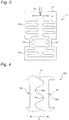
- a heater wire 114 may be provided at the hanging portion 110c in a comb-tooth like meandering shape.
- This comb-tooth like heater wire 114 is formed by connecting linear portions 114a, which extend in the widthwise direction D of the hanging portion 110c, and circular-arc portions 114b alternately.
- the comb-tooth like heater wire 114 is provided at the hanging portion 110c so that the predicted wrinkle line R does not pass through a vertex 114c of the circular-arc portion 114b of the comb-tooth like heater wire 114, especially so that the predicted wrinkle line R passes through a midpoint of succeeding two vertices 114c of the comb-tooth like heater wire 114 (i.e., passes through the heater wire 114 generally in parallel with the linear portion 114a).
- cutouts 10d are formed at both ends of the predicted wrinkle line R so that actual wrinkle lines occur along the predicted wrinkle lines R.
- cuts-in may be formed.
- a portion of the hanging portion 10c positioned between two cutouts 10d becomes lower in rigidity to bending deformation, as compared with its surrounding portions. Consequently, bending deformation of the hanging portion 10c bent at the predicted wrinkle line R is more likely to occur such that an actual wrinkle line occurs along the line connecting the two cutouts 10d together, i.e., along the predicted wrinkle line R.
- the heater wire 14 does not orthogonally intersect the predicted wrinkle lines R of the vehicle seat heater 10. Therefore, even if actual wrinkle lines occur along the predicted wrinkle lines R, disconnections are less likely to occur at the portions of the heater wire 14 intersecting the actual wrinkle lines. Thus, disconnections of the heater wire 14 caused by repeated deformations of the vehicle seat heater 10 can be suppressed.
- Embodiment 2 is similar to the above-described Embodiment 1 except the hanging portion of the vehicle seat heater. Therefore, the hanging portion only is described below.
- Fig. 6 shows a hanging portion of the seat heater according to this Embodiment 2.
- two reinforcing sheets 210e are attached in a hanging portion 210c with a predicted wrinkle line R sandwiched therebetween.
- a portion of the hanging portion 210c where the predicted wrinkle lines R is present i.e., a portion between the two reinforcing sheets 210e is made lower in rigidity, as compared with its surrounding portions.
- the reinforcing sheets 210e may be attached on one surface of the hanging portion 210c on which a heater wire 214 is provided or on its opposite-side surface, and moreover attached on both sides.
- wrinkle lines may occur also at portions other than the hanging portions.
- a corner 54c of the hanging groove 54a of the seat pad 54 is liable to change due to seating or releasing of the seat or postural changes during the seating.
- a portion of the vehicle seat heater 10 in contact with the corner 54c may be deformed, so that wrinkle lines may occur to the portion.
- a predicted wrinkle line at the portion of the vehicle seat heater 10 in contact with the corner 54c of the hanging groove 54a of the seat pad 54 is empirically or theoretically determined. Then, the heater wire 14 is laid in the base sheet 12 so that the heater wire 14 does not orthogonally intersect the determined predicted wrinkle line. As a result of this, disconnections of the heater wire 14 can be suppressed at portions of the vehicle seat heater 10 in contact with the corner 54c of the hanging groove 54a. Further, the portions of the vehicle seat heater 10 in contact with the corner 54c may be made lower in rigidity than in its surrounding portions, by forming cutouts (or cuts-in) (see Fig.
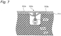
- a vehicle seat heater 310 is not hung on a cover-side hanging wire 352d but passed above a hanging groove 354a of a seat pad 354 (e.g., in a case where the vehicle seat heater 310 is fixed to seat covers 352a, 352b or the seat pad 354 via a Hook-and-Loop fastener), wrinkles are more likely to occur at portions of the vehicle seat heater 310 in contact with a sewed portion 352c of the seat covers 352a, 352b.
- predicted wrinkle lines are determined as in the foregoing embodiments, and a heater wire is laid in the base sheet so that the heater wire does not orthogonally intersect the determined predicted wrinkle lines.
- disconnections of the heater wire can be suppressed at portions of the vehicle seat heater 310 in contact with the sewed portion 352c of the seat covers 352a, 352b.
- the portions of the vehicle seat heater 310 in contact with the sewed portion 352c may be made lower in rigidity than in its surrounding portions, by forming cutouts (or cuts-in) (see Fig. 4 ), as with the predicted wrinkle lines R of the hanging portions, or by using reinforcing sheets (see Fig. 6 ), so that actual wrinkle lines occur along the predicted wrinkle lines at the portions of the vehicle seat heater 310 in contact with the sewed portion 352c.
- the heater wire is laid in the base sheet so that the heater wire does not orthogonally intersect the predicted wrinkle lines regardless of which portion of the vehicle seat heater.
- the vehicle seat heater according to the present invention may be provided not only in the central portion 50a or the front portion 50b of the vehicle seat 50 shown in Fig. 1 , but also in the backrest portion that supports the human back, only if predicted wrinkle lines can be determined empirically or theoretically.
Landscapes
- Engineering & Computer Science (AREA)
- Aviation & Aerospace Engineering (AREA)
- Transportation (AREA)
- Mechanical Engineering (AREA)
- Chair Legs, Seat Parts, And Backrests (AREA)
- Seats For Vehicles (AREA)
- Air-Conditioning For Vehicles (AREA)
Claims (8)
- Système de chauffage de siège de véhicule destiné à correspondre à un siège de véhicule, comprenant :une plaque de base ; etune résistance chauffante placée dans la plaque de base, dans laquellela résistance chauffante est placée de façon à ne pas entrer en intersection de manière perpendiculaire avec une ligne plissée prévue de la plaque de base ;caractérisé en ce qu'une partie du système de chauffage de siège de véhicule où se trouve la ligne plissée prévue est réalisée de façon à avoir une rigidité inférieure à celle des parties qui l'entourent.
- Système de chauffage de siège de véhicule selon la revendication 1, dans lequel une partie du système de chauffage de siège de véhicule où se trouve la ligne plissée prévue est positionnée entre deux plaques de renfort fixées à la plaque de base de façon à obtenir une rigidité inférieure.
- Système de chauffage de siège de véhicule selon la revendication 1, dans lequel des découpes ou des entailles sont formées aux deux extrémités de la ligne plissée prévue.
- Système de chauffage de siège de véhicule selon la revendication 1, dans lequel au niveau d'une partie suspendue du système de chauffage de siège de véhicule qui est insérée dans un renfoncement suspendu d'un coussin de siège du système de chauffage de siège de véhicule, la ligne plissée prévue est présente, s'étendant suivant une direction dans le sens de la largeur de la partie suspendue et dans la partie suspendue, la résistance chauffante s'étend de façon à serpenter suivant une direction perpendiculaire à la direction dans le sens de la largeur de la partie suspendue.
- Système de chauffage de siège de véhicule selon la revendication 4, dans lequel dans la partie suspendue, la ligne plissée prévue passe à travers et entre deux sommets successifs de la résistance chauffante en serpentin.
- Système de chauffage de siège de véhicule selon la revendication 1, dans lequel la ligne plissée prévue est présente à une partie du système de chauffage de siège de véhicule en contact avec un coin du renfoncement suspendu, et
la partie du système de chauffage de siège de véhicule en contact avec le coin du renfoncement suspendu est réalisée de façon à avoir une rigidité inférieure à celle des parties qui l'entourent. - Système de chauffage de siège de véhicule selon la revendication 1, dans lequel la ligne plissée prévue est présente à une partie du système de chauffage de siège de véhicule en contact avec une partie cousue d'une housse de siège du siège de véhicule, et
la partie du système de chauffage de siège de véhicule en contact avec la partie cousue de la housse de siège est réalisée de façon à avoir une rigidité inférieure à celle des parties qui l'entourent. - Système de chauffage de siège de véhicule destiné à correspondre à un siège de véhicule, comprenant :une plaque de base ; etune résistance chauffante placée dans la plaque de base, dans laquelleau niveau d'une partie suspendue de la plaque de base du système de chauffage de siège de véhicule qui est insérée dans un renfoncement suspendu d'un coussin de siège du système de chauffage de siège de véhicule, une ligne plissée prévue est définie, s'étendant suivant une direction dans le sens de la largeur de la partie suspendue,caractérisé en ce quedans la partie suspendue, la résistance chauffante est placée de façon à serpenter et s'étend suivant une direction perpendiculaire à la direction dans le sens de la largeur de la partie suspendue,une partie de la résistance chauffante est placée de manière linéaire dans la plaque de base, etune partie du résistance chauffante est placée le long de la ligne plissée prévue de la plaque de base de façon à ne pas entrer en intersection de manière perpendiculaire avec la ligne plissée prévue.
Applications Claiming Priority (1)
| Application Number | Priority Date | Filing Date | Title |
|---|---|---|---|
| PCT/JP2011/001331 WO2012120558A1 (fr) | 2011-03-07 | 2011-03-07 | Système de chauffage de siège de véhicule |
Publications (3)
| Publication Number | Publication Date |
|---|---|
| EP2684741A1 EP2684741A1 (fr) | 2014-01-15 |
| EP2684741A4 EP2684741A4 (fr) | 2015-11-18 |
| EP2684741B1 true EP2684741B1 (fr) | 2017-01-18 |
Family
ID=46794857
Family Applications (1)
| Application Number | Title | Priority Date | Filing Date |
|---|---|---|---|
| EP11860675.5A Active EP2684741B1 (fr) | 2011-03-07 | 2011-03-07 | Système de chauffage de siège de véhicule |
Country Status (5)
| Country | Link |
|---|---|
| US (1) | US8814262B2 (fr) |
| EP (1) | EP2684741B1 (fr) |
| JP (1) | JP5653365B2 (fr) |
| CN (1) | CN103097185B (fr) |
| WO (1) | WO2012120558A1 (fr) |
Families Citing this family (35)
| Publication number | Priority date | Publication date | Assignee | Title |
|---|---|---|---|---|
| DE112011101808T5 (de) | 2010-05-27 | 2013-05-16 | W.E.T.Automotive Systems Ltd. | Heizeinrichtung für ein Kraftfahrzeug und Verfahren zu deren Herstellung |
| US10201039B2 (en) | 2012-01-20 | 2019-02-05 | Gentherm Gmbh | Felt heater and method of making |
| JP5960545B2 (ja) * | 2012-08-13 | 2016-08-02 | テイ・エス テック株式会社 | 車両用シート |
| DE102012017047A1 (de) | 2012-08-29 | 2014-03-06 | W.E.T. Automotive Systems Ag | Elektrische Heizeinrichtung |
| JP6024528B2 (ja) | 2013-03-08 | 2016-11-16 | 株式会社デンソー | 乗員着座検知用荷重検出装置の取付け構造 |
| JP2014201244A (ja) * | 2013-04-08 | 2014-10-27 | 三菱自動車工業株式会社 | 車両用シート |
| JP6198934B2 (ja) * | 2013-05-02 | 2017-09-20 | ジェンサーム ゲーエムベーハー | 耐液加熱エレメント |
| CN103818287B (zh) * | 2014-02-28 | 2016-06-22 | 天津博信汽车零部件有限公司 | 一种汽车座椅加热垫 |
| JP6292003B2 (ja) * | 2014-04-25 | 2018-03-14 | トヨタ紡織株式会社 | 乗物用シート |
| US20150366003A1 (en) * | 2014-06-16 | 2015-12-17 | Sceiba Intelligent Fashion Co., Ltd. | Electric heating module |
| WO2016029011A1 (fr) * | 2014-08-20 | 2016-02-25 | Faurecia Automotive Seating, Llc. | Coussin de siège et procédé de fabrication de celui-ci |
| CA2911134A1 (fr) * | 2014-11-04 | 2016-05-04 | Magna Seating Inc. | Siege chaud/froid instantanement |
| US20180257524A1 (en) * | 2014-11-21 | 2018-09-13 | Kongsberg Automotive Ab | Heating Device For A Seat Heater Of A Motor Vehicle |
| JP6043972B1 (ja) * | 2015-04-08 | 2016-12-14 | パナソニックIpマネジメント株式会社 | シートヒータ |
| US10538868B2 (en) * | 2015-09-08 | 2020-01-21 | Igb Automotive Ltd. | Seat heater and method of its fabrication |
| DE102015116689A1 (de) * | 2015-10-01 | 2017-04-06 | Kongsberg Automotive Ab | Heiz- und Ventilationseinlage für einen Fahrzeugsitz |
| JP6634306B2 (ja) * | 2016-02-09 | 2020-01-22 | 株式会社タチエス | シートカバー及び車両用シート |
| US10442328B2 (en) | 2016-06-21 | 2019-10-15 | Kongsberg Automotive Ab | Assembly, system, and circuit with combined heating and occupancy detecting for a vehicle seat |
| JP2018075872A (ja) * | 2016-11-07 | 2018-05-17 | テイ・エス テック株式会社 | 車両用シート |
| DE102017001097A1 (de) | 2017-02-07 | 2018-08-09 | Gentherm Gmbh | Elektrisch leitfähige Folie |
| JP6889367B2 (ja) * | 2017-03-01 | 2021-06-18 | テイ・エス テック株式会社 | 乗物用シート |
| JP7133905B2 (ja) * | 2017-04-11 | 2022-09-09 | 株式会社クラベ | ヒータユニット及び車両用シート |
| US10966535B2 (en) | 2017-05-30 | 2021-04-06 | Ford Global Technologies, Llc | Thermally conductive tape |
| US10363845B2 (en) * | 2017-05-30 | 2019-07-30 | Ford Global Technologies, Llc | Conductive system |
| US10737597B2 (en) | 2017-05-30 | 2020-08-11 | Ford Global Technologies, Llc | Conductive system |
| US10700253B2 (en) | 2017-05-30 | 2020-06-30 | Ford Global Technologies, Llc | Conductive tape recess |
| JP7236000B2 (ja) * | 2017-06-19 | 2023-03-09 | テイ・エス テック株式会社 | 乗物用シート |
| JP6970335B2 (ja) | 2017-06-19 | 2021-11-24 | テイ・エス テック株式会社 | 乗物用シート |
| JP6925930B2 (ja) * | 2017-10-20 | 2021-08-25 | 株式会社タチエス | 乗物用シート |
| JP2018052498A (ja) * | 2018-01-10 | 2018-04-05 | テイ・エス テック株式会社 | 車両用シート |
| CN109318769B (zh) * | 2018-09-03 | 2023-11-28 | 江阴神辉电工材料有限公司 | 快速发热节能型自调节汽车座椅加热垫 |
| US11091076B1 (en) * | 2020-01-31 | 2021-08-17 | Faurecia Automotive Seating, Llc | Seat back heater mat attachment |
| KR102890511B1 (ko) * | 2020-03-26 | 2025-11-24 | 린텍 가부시키가이샤 | 시트상 도전 부재 및 시트상 히터 |
| US11312273B1 (en) * | 2021-03-25 | 2022-04-26 | Faurecia Automotive Seating, Llc | Method and apparatus for mat retention in a seat assembly |
| JP7421130B2 (ja) * | 2021-03-30 | 2024-01-24 | テイ・エス テック株式会社 | 車両用シートおよび車両用シートの製造方法 |
Family Cites Families (21)
| Publication number | Priority date | Publication date | Assignee | Title |
|---|---|---|---|---|
| US2943620A (en) * | 1958-02-24 | 1960-07-05 | Frank J Sibert | Pillow or cushion type vibrator |
| JPS5851797Y2 (ja) * | 1978-08-18 | 1983-11-25 | 松下電器産業株式会社 | 座いすヒ−タ |
| US4459471A (en) * | 1981-10-26 | 1984-07-10 | Hulett John G | Electrical heating cap |
| JPH05293023A (ja) * | 1992-04-21 | 1993-11-09 | Matsushita Electric Ind Co Ltd | ヒータユニット |
| JPH065352A (ja) | 1992-06-18 | 1994-01-14 | Matsushita Electric Ind Co Ltd | 車両用座席のヒータユニット |
| US5516189A (en) * | 1994-11-14 | 1996-05-14 | Ligeras; Achilles P. | Portable heated seat |
| EP1647212A3 (fr) * | 1999-09-22 | 2006-08-16 | Matsushita Electric Industrial Co., Ltd. | Dispositif de chauffage de surface |
| JP2001327551A (ja) * | 2000-03-13 | 2001-11-27 | Sakura Aluminum Kk | マットレス及び医療用寝具 |
| FR2815901B1 (fr) * | 2000-10-31 | 2003-08-08 | Faurecia Sieges Automobile | Element rembourre pour vehicule et son procede de fabrication |
| JP4356243B2 (ja) * | 2001-01-12 | 2009-11-04 | 株式会社デンソー | 乗員着座センサの取付け構造 |
| US9963056B2 (en) * | 2001-09-20 | 2018-05-08 | Kurabe Industrial Co., Ltd. | Seat heater and a manufacturing method of seat heater |
| WO2004014169A2 (fr) * | 2002-08-07 | 2004-02-19 | Phoenix Consultants, Ltd | Vêtement à régulation de température |
| JP4273752B2 (ja) | 2002-11-26 | 2009-06-03 | パナソニック株式会社 | シートヒータおよびそれを装着した自動車用座席 |
| US6918144B2 (en) * | 2003-04-04 | 2005-07-19 | Michael Friedman | Self-heating portable massage table |
| DE10357583B3 (de) * | 2003-12-08 | 2005-03-17 | W.E.T. Automotive Systems Ag | Luftverteilungseinrichtung für eine Baueinheit im Fahrgastraum |
| JP2007253845A (ja) * | 2006-03-24 | 2007-10-04 | Matsushita Electric Ind Co Ltd | 面状発熱体 |
| US7307242B1 (en) * | 2006-06-23 | 2007-12-11 | Mec Addheat Company | Heating device of a glove |
| US8143554B2 (en) * | 2007-03-16 | 2012-03-27 | Amerigon Incorporated | Air warmer |
| JP4861450B2 (ja) * | 2009-05-12 | 2012-01-25 | 日本発條株式会社 | 車両用シート装置及びそれに使用されるヒータ・ユニット |
| CN102450091A (zh) * | 2009-05-26 | 2012-05-09 | 松下电器产业株式会社 | 面状采暖器以及具备该面状采暖器的座椅 |
| US8567861B2 (en) * | 2009-12-25 | 2013-10-29 | Ts Tech Co., Ltd. | Seat with heater |
-
2011
- 2011-03-07 WO PCT/JP2011/001331 patent/WO2012120558A1/fr not_active Ceased
- 2011-03-07 US US13/259,520 patent/US8814262B2/en active Active
- 2011-03-07 JP JP2011545557A patent/JP5653365B2/ja active Active
- 2011-03-07 CN CN201180001891.7A patent/CN103097185B/zh active Active
- 2011-03-07 EP EP11860675.5A patent/EP2684741B1/fr active Active
Non-Patent Citations (1)
| Title |
|---|
| None * |
Also Published As
| Publication number | Publication date |
|---|---|
| EP2684741A1 (fr) | 2014-01-15 |
| JP5653365B2 (ja) | 2015-01-14 |
| US20120228903A1 (en) | 2012-09-13 |
| US8814262B2 (en) | 2014-08-26 |
| CN103097185B (zh) | 2015-12-16 |
| WO2012120558A1 (fr) | 2012-09-13 |
| EP2684741A4 (fr) | 2015-11-18 |
| CN103097185A (zh) | 2013-05-08 |
| JPWO2012120558A1 (ja) | 2014-07-07 |
Similar Documents
| Publication | Publication Date | Title |
|---|---|---|
| EP2684741A1 (fr) | Système de chauffage de siège de véhicule | |
| EP2883479B1 (fr) | Siège de véhicule | |
| TWI630129B (zh) | Vehicle seat | |
| US8919878B2 (en) | Vehicle seat | |
| US9573503B2 (en) | Vehicle seat | |
| EP3418112B1 (fr) | Siège de véhicule | |
| CN101678786B (zh) | 软座元件 | |
| US10071660B2 (en) | Vehicle seat | |
| EP2684740B1 (fr) | Système de chauffage de siège de véhicule | |
| JP7236000B2 (ja) | 乗物用シート | |
| JP2020128116A (ja) | シートヒータ | |
| EP2934065B1 (fr) | Elément chauffant de siège et revêtement de siège le comportant | |
| JP7518436B2 (ja) | 乗物用シート | |
| JP2016166018A (ja) | 車両用シート | |
| JP2012192761A (ja) | 車両用シート | |
| JP7021892B2 (ja) | 車両用シート | |
| JP2003212018A (ja) | 電界検出式着座センサのアンテナユニット | |
| JP7684549B2 (ja) | 乗物用シート | |
| JP2017186012A (ja) | 車両用シート | |
| JP5589828B2 (ja) | 車両用シート | |
| JP2015151017A (ja) | 乗物用シート |
Legal Events
| Date | Code | Title | Description |
|---|---|---|---|
| PUAI | Public reference made under article 153(3) epc to a published international application that has entered the european phase |
Free format text: ORIGINAL CODE: 0009012 |
|
| 17P | Request for examination filed |
Effective date: 20130628 |
|
| AK | Designated contracting states |
Kind code of ref document: A1 Designated state(s): AL AT BE BG CH CY CZ DE DK EE ES FI FR GB GR HR HU IE IS IT LI LT LU LV MC MK MT NL NO PL PT RO RS SE SI SK SM TR |
|
| DAX | Request for extension of the european patent (deleted) | ||
| RAP1 | Party data changed (applicant data changed or rights of an application transferred) |
Owner name: PANASONIC INTELLECTUAL PROPERTY MANAGEMENT CO., LT |
|
| RAP1 | Party data changed (applicant data changed or rights of an application transferred) |
Owner name: PANASONIC INTELLECTUAL PROPERTY MANAGEMENT CO., LT |
|
| RA4 | Supplementary search report drawn up and despatched (corrected) |
Effective date: 20151016 |
|
| RIC1 | Information provided on ipc code assigned before grant |
Ipc: A47C 7/74 20060101ALI20151012BHEP Ipc: A47C 31/11 20060101ALI20151012BHEP Ipc: B60N 2/44 20060101AFI20151012BHEP Ipc: B60N 2/56 20060101ALI20151012BHEP Ipc: H05B 3/20 20060101ALI20151012BHEP |
|
| GRAP | Despatch of communication of intention to grant a patent |
Free format text: ORIGINAL CODE: EPIDOSNIGR1 |
|
| RIC1 | Information provided on ipc code assigned before grant |
Ipc: A47C 31/11 20060101ALI20160627BHEP Ipc: B60N 2/44 20060101AFI20160627BHEP Ipc: B60N 2/56 20060101ALI20160627BHEP Ipc: A47C 7/74 20060101ALI20160627BHEP Ipc: H05B 3/20 20060101ALI20160627BHEP |
|
| INTG | Intention to grant announced |
Effective date: 20160712 |
|
| GRAS | Grant fee paid |
Free format text: ORIGINAL CODE: EPIDOSNIGR3 |
|
| GRAJ | Information related to disapproval of communication of intention to grant by the applicant or resumption of examination proceedings by the epo deleted |
Free format text: ORIGINAL CODE: EPIDOSDIGR1 |
|
| GRAL | Information related to payment of fee for publishing/printing deleted |
Free format text: ORIGINAL CODE: EPIDOSDIGR3 |
|
| GRAR | Information related to intention to grant a patent recorded |
Free format text: ORIGINAL CODE: EPIDOSNIGR71 |
|
| INTC | Intention to grant announced (deleted) | ||
| GRAA | (expected) grant |
Free format text: ORIGINAL CODE: 0009210 |
|
| INTG | Intention to grant announced |
Effective date: 20161207 |
|
| AK | Designated contracting states |
Kind code of ref document: B1 Designated state(s): AL AT BE BG CH CY CZ DE DK EE ES FI FR GB GR HR HU IE IS IT LI LT LU LV MC MK MT NL NO PL PT RO RS SE SI SK SM TR |
|
| REG | Reference to a national code |
Ref country code: GB Ref legal event code: FG4D |
|
| REG | Reference to a national code |
Ref country code: CH Ref legal event code: EP |
|
| REG | Reference to a national code |
Ref country code: AT Ref legal event code: REF Ref document number: 862700 Country of ref document: AT Kind code of ref document: T Effective date: 20170215 |
|
| REG | Reference to a national code |
Ref country code: IE Ref legal event code: FG4D |
|
| REG | Reference to a national code |
Ref country code: DE Ref legal event code: R096 Ref document number: 602011034567 Country of ref document: DE |
|
| REG | Reference to a national code |
Ref country code: FR Ref legal event code: PLFP Year of fee payment: 7 |
|
| REG | Reference to a national code |
Ref country code: NL Ref legal event code: MP Effective date: 20170118 |
|
| REG | Reference to a national code |
Ref country code: LT Ref legal event code: MG4D |
|
| REG | Reference to a national code |
Ref country code: AT Ref legal event code: MK05 Ref document number: 862700 Country of ref document: AT Kind code of ref document: T Effective date: 20170118 |
|
| PG25 | Lapsed in a contracting state [announced via postgrant information from national office to epo] |
Ref country code: NL Free format text: LAPSE BECAUSE OF FAILURE TO SUBMIT A TRANSLATION OF THE DESCRIPTION OR TO PAY THE FEE WITHIN THE PRESCRIBED TIME-LIMIT Effective date: 20170118 |
|
| PG25 | Lapsed in a contracting state [announced via postgrant information from national office to epo] |
Ref country code: GR Free format text: LAPSE BECAUSE OF FAILURE TO SUBMIT A TRANSLATION OF THE DESCRIPTION OR TO PAY THE FEE WITHIN THE PRESCRIBED TIME-LIMIT Effective date: 20170419 Ref country code: LT Free format text: LAPSE BECAUSE OF FAILURE TO SUBMIT A TRANSLATION OF THE DESCRIPTION OR TO PAY THE FEE WITHIN THE PRESCRIBED TIME-LIMIT Effective date: 20170118 Ref country code: IS Free format text: LAPSE BECAUSE OF FAILURE TO SUBMIT A TRANSLATION OF THE DESCRIPTION OR TO PAY THE FEE WITHIN THE PRESCRIBED TIME-LIMIT Effective date: 20170518 Ref country code: HR Free format text: LAPSE BECAUSE OF FAILURE TO SUBMIT A TRANSLATION OF THE DESCRIPTION OR TO PAY THE FEE WITHIN THE PRESCRIBED TIME-LIMIT Effective date: 20170118 Ref country code: FI Free format text: LAPSE BECAUSE OF FAILURE TO SUBMIT A TRANSLATION OF THE DESCRIPTION OR TO PAY THE FEE WITHIN THE PRESCRIBED TIME-LIMIT Effective date: 20170118 Ref country code: NO Free format text: LAPSE BECAUSE OF FAILURE TO SUBMIT A TRANSLATION OF THE DESCRIPTION OR TO PAY THE FEE WITHIN THE PRESCRIBED TIME-LIMIT Effective date: 20170418 |
|
| PG25 | Lapsed in a contracting state [announced via postgrant information from national office to epo] |
Ref country code: PT Free format text: LAPSE BECAUSE OF FAILURE TO SUBMIT A TRANSLATION OF THE DESCRIPTION OR TO PAY THE FEE WITHIN THE PRESCRIBED TIME-LIMIT Effective date: 20170518 Ref country code: PL Free format text: LAPSE BECAUSE OF FAILURE TO SUBMIT A TRANSLATION OF THE DESCRIPTION OR TO PAY THE FEE WITHIN THE PRESCRIBED TIME-LIMIT Effective date: 20170118 Ref country code: RS Free format text: LAPSE BECAUSE OF FAILURE TO SUBMIT A TRANSLATION OF THE DESCRIPTION OR TO PAY THE FEE WITHIN THE PRESCRIBED TIME-LIMIT Effective date: 20170118 Ref country code: AT Free format text: LAPSE BECAUSE OF FAILURE TO SUBMIT A TRANSLATION OF THE DESCRIPTION OR TO PAY THE FEE WITHIN THE PRESCRIBED TIME-LIMIT Effective date: 20170118 Ref country code: ES Free format text: LAPSE BECAUSE OF FAILURE TO SUBMIT A TRANSLATION OF THE DESCRIPTION OR TO PAY THE FEE WITHIN THE PRESCRIBED TIME-LIMIT Effective date: 20170118 Ref country code: LV Free format text: LAPSE BECAUSE OF FAILURE TO SUBMIT A TRANSLATION OF THE DESCRIPTION OR TO PAY THE FEE WITHIN THE PRESCRIBED TIME-LIMIT Effective date: 20170118 Ref country code: SE Free format text: LAPSE BECAUSE OF FAILURE TO SUBMIT A TRANSLATION OF THE DESCRIPTION OR TO PAY THE FEE WITHIN THE PRESCRIBED TIME-LIMIT Effective date: 20170118 Ref country code: BG Free format text: LAPSE BECAUSE OF FAILURE TO SUBMIT A TRANSLATION OF THE DESCRIPTION OR TO PAY THE FEE WITHIN THE PRESCRIBED TIME-LIMIT Effective date: 20170418 |
|
| REG | Reference to a national code |
Ref country code: DE Ref legal event code: R097 Ref document number: 602011034567 Country of ref document: DE |
|
| PG25 | Lapsed in a contracting state [announced via postgrant information from national office to epo] |
Ref country code: EE Free format text: LAPSE BECAUSE OF FAILURE TO SUBMIT A TRANSLATION OF THE DESCRIPTION OR TO PAY THE FEE WITHIN THE PRESCRIBED TIME-LIMIT Effective date: 20170118 Ref country code: SK Free format text: LAPSE BECAUSE OF FAILURE TO SUBMIT A TRANSLATION OF THE DESCRIPTION OR TO PAY THE FEE WITHIN THE PRESCRIBED TIME-LIMIT Effective date: 20170118 Ref country code: IT Free format text: LAPSE BECAUSE OF FAILURE TO SUBMIT A TRANSLATION OF THE DESCRIPTION OR TO PAY THE FEE WITHIN THE PRESCRIBED TIME-LIMIT Effective date: 20170118 Ref country code: RO Free format text: LAPSE BECAUSE OF FAILURE TO SUBMIT A TRANSLATION OF THE DESCRIPTION OR TO PAY THE FEE WITHIN THE PRESCRIBED TIME-LIMIT Effective date: 20170118 Ref country code: CZ Free format text: LAPSE BECAUSE OF FAILURE TO SUBMIT A TRANSLATION OF THE DESCRIPTION OR TO PAY THE FEE WITHIN THE PRESCRIBED TIME-LIMIT Effective date: 20170118 |
|
| REG | Reference to a national code |
Ref country code: CH Ref legal event code: PL |
|
| PLBE | No opposition filed within time limit |
Free format text: ORIGINAL CODE: 0009261 |
|
| STAA | Information on the status of an ep patent application or granted ep patent |
Free format text: STATUS: NO OPPOSITION FILED WITHIN TIME LIMIT |
|
| REG | Reference to a national code |
Ref country code: DE Ref legal event code: R079 Ref document number: 602011034567 Country of ref document: DE Free format text: PREVIOUS MAIN CLASS: B60N0002440000 Ipc: B60N0002900000 |
|
| PG25 | Lapsed in a contracting state [announced via postgrant information from national office to epo] |
Ref country code: DK Free format text: LAPSE BECAUSE OF FAILURE TO SUBMIT A TRANSLATION OF THE DESCRIPTION OR TO PAY THE FEE WITHIN THE PRESCRIBED TIME-LIMIT Effective date: 20170118 Ref country code: MC Free format text: LAPSE BECAUSE OF FAILURE TO SUBMIT A TRANSLATION OF THE DESCRIPTION OR TO PAY THE FEE WITHIN THE PRESCRIBED TIME-LIMIT Effective date: 20170118 Ref country code: SM Free format text: LAPSE BECAUSE OF FAILURE TO SUBMIT A TRANSLATION OF THE DESCRIPTION OR TO PAY THE FEE WITHIN THE PRESCRIBED TIME-LIMIT Effective date: 20170118 |
|
| 26N | No opposition filed |
Effective date: 20171019 |
|
| REG | Reference to a national code |
Ref country code: IE Ref legal event code: MM4A |
|
| PG25 | Lapsed in a contracting state [announced via postgrant information from national office to epo] |
Ref country code: LU Free format text: LAPSE BECAUSE OF NON-PAYMENT OF DUE FEES Effective date: 20170307 |
|
| PG25 | Lapsed in a contracting state [announced via postgrant information from national office to epo] |
Ref country code: SI Free format text: LAPSE BECAUSE OF FAILURE TO SUBMIT A TRANSLATION OF THE DESCRIPTION OR TO PAY THE FEE WITHIN THE PRESCRIBED TIME-LIMIT Effective date: 20170118 Ref country code: IE Free format text: LAPSE BECAUSE OF NON-PAYMENT OF DUE FEES Effective date: 20170307 Ref country code: LI Free format text: LAPSE BECAUSE OF NON-PAYMENT OF DUE FEES Effective date: 20170331 Ref country code: CH Free format text: LAPSE BECAUSE OF NON-PAYMENT OF DUE FEES Effective date: 20170331 |
|
| REG | Reference to a national code |
Ref country code: BE Ref legal event code: MM Effective date: 20170331 |
|
| REG | Reference to a national code |
Ref country code: FR Ref legal event code: PLFP Year of fee payment: 8 |
|
| PG25 | Lapsed in a contracting state [announced via postgrant information from national office to epo] |
Ref country code: BE Free format text: LAPSE BECAUSE OF NON-PAYMENT OF DUE FEES Effective date: 20170331 |
|
| PG25 | Lapsed in a contracting state [announced via postgrant information from national office to epo] |
Ref country code: MT Free format text: LAPSE BECAUSE OF NON-PAYMENT OF DUE FEES Effective date: 20170307 |
|
| REG | Reference to a national code |
Ref country code: DE Ref legal event code: R084 Ref document number: 602011034567 Country of ref document: DE |
|
| PG25 | Lapsed in a contracting state [announced via postgrant information from national office to epo] |
Ref country code: HU Free format text: LAPSE BECAUSE OF FAILURE TO SUBMIT A TRANSLATION OF THE DESCRIPTION OR TO PAY THE FEE WITHIN THE PRESCRIBED TIME-LIMIT; INVALID AB INITIO Effective date: 20110307 |
|
| PG25 | Lapsed in a contracting state [announced via postgrant information from national office to epo] |
Ref country code: CY Free format text: LAPSE BECAUSE OF NON-PAYMENT OF DUE FEES Effective date: 20170118 |
|
| PG25 | Lapsed in a contracting state [announced via postgrant information from national office to epo] |
Ref country code: MK Free format text: LAPSE BECAUSE OF FAILURE TO SUBMIT A TRANSLATION OF THE DESCRIPTION OR TO PAY THE FEE WITHIN THE PRESCRIBED TIME-LIMIT Effective date: 20170118 |
|
| PG25 | Lapsed in a contracting state [announced via postgrant information from national office to epo] |
Ref country code: TR Free format text: LAPSE BECAUSE OF FAILURE TO SUBMIT A TRANSLATION OF THE DESCRIPTION OR TO PAY THE FEE WITHIN THE PRESCRIBED TIME-LIMIT Effective date: 20170118 |
|
| PG25 | Lapsed in a contracting state [announced via postgrant information from national office to epo] |
Ref country code: AL Free format text: LAPSE BECAUSE OF FAILURE TO SUBMIT A TRANSLATION OF THE DESCRIPTION OR TO PAY THE FEE WITHIN THE PRESCRIBED TIME-LIMIT Effective date: 20170118 |
|
| REG | Reference to a national code |
Ref country code: DE Ref legal event code: R081 Ref document number: 602011034567 Country of ref document: DE Owner name: PANASONIC AUTOMOTIVE SYSTEMS CO., LTD., YOKOHA, JP Free format text: FORMER OWNER: PANASONIC INTELLECTUAL PROPERTY MANAGEMENT CO., LTD., OSAKA, JP |
|
| REG | Reference to a national code |
Ref country code: GB Ref legal event code: 732E Free format text: REGISTERED BETWEEN 20240704 AND 20240710 |
|
| REG | Reference to a national code |
Ref country code: DE Ref legal event code: R082 Ref document number: 602011034567 Country of ref document: DE Representative=s name: DENNEMEYER & ASSOCIATES RECHTSANWALTSGESELLSCH, DE |
|
| PGFP | Annual fee paid to national office [announced via postgrant information from national office to epo] |
Ref country code: FR Payment date: 20250325 Year of fee payment: 15 |
|
| PGFP | Annual fee paid to national office [announced via postgrant information from national office to epo] |
Ref country code: GB Payment date: 20250321 Year of fee payment: 15 |
|
| PGFP | Annual fee paid to national office [announced via postgrant information from national office to epo] |
Ref country code: DE Payment date: 20260319 Year of fee payment: 16 |