EP2685018A2 - Dispositif de logement à découplage d'oscillations d'une partie de bâtiment en porte-à-faux - Google Patents
Dispositif de logement à découplage d'oscillations d'une partie de bâtiment en porte-à-faux Download PDFInfo
- Publication number
- EP2685018A2 EP2685018A2 EP13173709.0A EP13173709A EP2685018A2 EP 2685018 A2 EP2685018 A2 EP 2685018A2 EP 13173709 A EP13173709 A EP 13173709A EP 2685018 A2 EP2685018 A2 EP 2685018A2
- Authority
- EP
- European Patent Office
- Prior art keywords
- building
- projecting
- carrier element
- building part
- decoupling means
- Prior art date
- Legal status (The legal status is an assumption and is not a legal conclusion. Google has not performed a legal analysis and makes no representation as to the accuracy of the status listed.)
- Withdrawn
Links
- 230000008878 coupling Effects 0.000 claims abstract description 8
- 238000010168 coupling process Methods 0.000 claims abstract description 8
- 238000005859 coupling reaction Methods 0.000 claims abstract description 8
- 230000003014 reinforcing effect Effects 0.000 claims description 22
- 238000009413 insulation Methods 0.000 claims description 9
- 230000002787 reinforcement Effects 0.000 claims description 6
- 230000000694 effects Effects 0.000 description 9
- 230000004888 barrier function Effects 0.000 description 3
- 230000008901 benefit Effects 0.000 description 3
- 239000003795 chemical substances by application Substances 0.000 description 3
- 229920001971 elastomer Polymers 0.000 description 3
- 230000005540 biological transmission Effects 0.000 description 2
- 238000000576 coating method Methods 0.000 description 2
- 230000006835 compression Effects 0.000 description 2
- 238000007906 compression Methods 0.000 description 2
- 239000000806 elastomer Substances 0.000 description 2
- 238000009434 installation Methods 0.000 description 2
- 238000002955 isolation Methods 0.000 description 2
- 239000002184 metal Substances 0.000 description 2
- 230000000704 physical effect Effects 0.000 description 2
- 229910000831 Steel Inorganic materials 0.000 description 1
- 230000002238 attenuated effect Effects 0.000 description 1
- 230000015572 biosynthetic process Effects 0.000 description 1
- 239000011248 coating agent Substances 0.000 description 1
- 238000013016 damping Methods 0.000 description 1
- 239000013013 elastic material Substances 0.000 description 1
- 239000006260 foam Substances 0.000 description 1
- 239000000463 material Substances 0.000 description 1
- 230000035515 penetration Effects 0.000 description 1
- 239000004033 plastic Substances 0.000 description 1
- 230000009467 reduction Effects 0.000 description 1
- 125000006850 spacer group Chemical group 0.000 description 1
- 230000007480 spreading Effects 0.000 description 1
- 239000010959 steel Substances 0.000 description 1
- 230000007704 transition Effects 0.000 description 1
- 230000000007 visual effect Effects 0.000 description 1
Images




Classifications
-
- E—FIXED CONSTRUCTIONS
- E04—BUILDING
- E04B—GENERAL BUILDING CONSTRUCTIONS; WALLS, e.g. PARTITIONS; ROOFS; FLOORS; CEILINGS; INSULATION OR OTHER PROTECTION OF BUILDINGS
- E04B1/00—Constructions in general; Structures which are not restricted either to walls, e.g. partitions, or floors or ceilings or roofs
- E04B1/003—Balconies; Decks
Definitions
- the invention relates to a device for at least vibration-decoupled support of a projecting building part, according to the preamble of claim 1, and to a cantilevered component according to claim 13.
- Such devices are used to construct a first part of the building which is subject to external influences, such as e.g. Impact loads is exposed, so from a second building part, with which it is structurally connected to decouple that the effects due to the effects, e.g. Vibrations, not or only reduced transferred from the first part of the building to the second part of the building.
- Devices are known, for example, which have completely through an outer building wall extending therethrough support elements which are coated on the upper side with an elastic element and are superimposed by a walk-in area.
- Such devices have the disadvantage that they form a thermal or cold bridge, by which the effects of building insulation are bypassed.
- building insulation seeks to maintain any temperature differences between the interior of the building and the exterior of the building, i. To decouple the climate and the temperature inside the building from the environment, run through the building insulation support elements undergo these efforts, causing high heat loss and comfort losses occur.
- devices which have completely through an outer building wall extending therethrough support elements, which in the region of the building wall partly have a reduced cross-section in order to reduce the heat transfer out of the building or into the building.
- Such devices may further include horizontal coatings for absorbing impact sound.
- the disadvantage here is that due to the continuous support elements further heat transfer is possible and depending on the coating and impact sound is directed into the building interior.
- a device for vibration-decoupled support of a projecting building part preferably comprises at least or exactly one longitudinally extending carrier element for receiving the projecting building part, the carrier element forming a first end region and a second end region spaced from the first end region in the longitudinal direction, and wherein a longitudinally extending surface of the carrier element at least partially through the projecting building part is superimposed.
- the device comprises a vibration decoupling means, which can be arranged or formed for spacing the projecting building part from the carrier element between the projecting building part and the carrier element.
- the carrier element has at least one coupling point in the first end region for connection to a fixing device which transmits tensile forces in the longitudinal direction of the carrier, by way of which the carrier element can be fixed to a supporting building part together with the projecting component.
- the carrier element here is preferably to be understood as meaning any element which extends in an elongated manner and which is loadable orthogonally to its longitudinal direction. In this case, however, particularly preferably metal, in particular steel beams, are used.
- the carrier element has at least one body edge delimiting the first end region in the longitudinal direction, which extends in a preferably substantially or exactly perpendicular to the longitudinal direction oriented plane for contacting with the further decoupling means.
- contacting in this case is preferably a direct contacting and thus a point, line or surface contact to understand.
- the contact between the carrier element and the further decoupling means or the indirect contact between the carrier element and the further building part is preferably designed such that the carrier element non-positively and / or positively, in particular by means of screws, is rigidly connected to the other part of the building.
- the decoupling means can be arranged at the first end of the carrier element and can provide in the longitudinal direction of the carrier element between the carrier element and the further building part.
- the further decoupling means superimposed in the longitudinal direction, at least in sections, an outer boundary surface of a further building part, on which the projecting building part can be arranged.
- vibration decoupling means and the further decoupling means extend in two preferably substantially or exactly orthogonal planes.
- This causes, for example, the transmission of a special effect, e.g. Vibrations, improved is reducible.
- various effects, in particular e.g. Vibrations and temperature transfers specifically reduced by the optimal design and tuning of the respective decoupling.
- the fixing device is also designed for transmitting tensile forces and / or pressure forces and / or shear forces between the carrier element and the further building part.
- the fixing device may in this case be e.g. from a load distribution plate and thus connectable or can be brought into contact screw elements, be formed.
- the screw elements may be e.g. be executed as nuts.
- between the nuts and the load distribution plate washers are provided for improved load application.
- this embodiment is advantageous because a stable arrangement of the cantilevered component on the further part of the building, in particular a wall and / or a floor or ceiling part, is possible by means of the fixing device.
- the fixing device for transmitting the tensile, compressive and / or transverse forces comprises elongated reinforcing elements, which are arranged in a receiving means which is fixedly arranged on the other part of the building, stationary and arranged with the support element are detachably connected or connectable.
- the reinforcing elements may in this case be designed, for example, rod-shaped or plate-shaped.
- An advantage of this embodiment is, for example, that the reinforcing elements are arranged in a receiving means such that they are always held stationary regardless of the load. It is thus proposed an extremely stable, safe and durable arrangement.
- the receiving means may be releasably or permanently connected to the other part of the building and / or a wall part, preferably, the reinforcing elements are also arranged at least partially enclosed by the other part of the building.
- the reinforcing elements are at least partially enclosed by the further decoupling means.
- the reinforcing elements or portions of the reinforcing elements extend at least in sections preferably in the carrier longitudinal direction through the further decoupling means.
- a further plate-like device in particular a metal plate equipped with holes or coupling elements arranged, through which the reinforcing elements extend through and is coupled to the at least one reinforcing element.
- the reinforcing elements may for example be made of several parts, whereby by means of the plate-like device, a coupling of fixedly arranged in the receiving means shares with the passable through the further decoupling means or with the fixable on the support member shares is possible.
- the further decoupling means may be formed as a material layer, which is in particular positively, materially or frictionally connected to the cantilevered building part and / or to the other part of the building. It is conceivable here that the further decoupling means consists of an elastic material, such as rubber or plastic.
- the embodiment provides an intermediate region between the projecting building part and the other part of the building.
- This intermediate area preferably serves as a temperature barrier, by which the penetration of heat into the further part of the building or the removal of heat from the other part of the building is prevented or reduced.
- the further decoupling means can be arranged between a surface portion formed by the projecting building part and a surface portion of the further building part which is substantially parallel thereto.
- the surface portions preferably extend in the vertical direction. It is conceivable here that the further decoupling means is arranged or formed only on one side of the carrier element on the projecting building part.
- This embodiment is advantageous because it represents a substantially independent of the configuration of the reinforcing elements and the fixing device and thus easy to implement arrangement.
- the projecting building part is provided before installation on the other part of the building with the decoupling means and / or the further decoupling means.
- the portions of the carrier element superimposed by the projecting building part are also at least partially and preferably completely laterally encompassed by the projecting building part.
- the portions of the carrier element superposed by the projecting building part are completely enclosed by the projecting building part.
- This embodiment is advantageous since the support element, even if the projecting building part is viewed from below, can be arranged completely invisible and protected from the weather.
- the vibration decoupling means is suitable for impact sound insulation and the further decoupling means is suitable for thermal decoupling.
- This embodiment is advantageous since the effects acting on the projecting building part can be reduced to the ideal points in an optimized manner.
- those represented by e.g. Sound produced impact sound preferably attenuated directly in the direction of origin
- the further decoupling means is a temperature barrier, which is particularly preferably formed directly in a transition region between cantilevered building part and the building exterior.
- a multiple decoupling in particular different physical effects.
- the present invention thus provides a barrier through which the physical effects, e.g. Noise and / or temperature transfer, be prevented from spreading.
- the projecting part of the building is preferably a balcony and the other part of the building is a load-bearing part of the building, the balcony being particularly preferably always arranged outside a building and thus on the outside of the building and the other part of the building on the inside of the building.
- the invention also relates to a projecting building part, in particular a balcony, wherein at least one receiving area is provided in or on the projecting building part, which is designed for connection to a device according to one of the aforementioned embodiments.
- Fig. 1 the device 1 is shown in cross-section along the longitudinal direction X.
- the device 1 serves to vibrationally decoupled support a balcony slab 2 against another building part 24, here a building wall.
- the balcony slab 2 forms the projecting part of the building, which is also referred to above as an object enclosing at least one support element 4.
- the carrier element 4 is enclosed along its longitudinal extent in the circumferential direction by the balcony plate 2 and is also covered in an end region 8 of frontal wall parts 54 of the balcony slab 2.
- the carrier element 4 is provided on its upper surface 10 with a vibration decoupling means 12 in the form of an elastomeric plate serving as a footfall sound insulation.
- the carrier element 4 is only indirectly in contact with the balcony slab 2, ie the vibration decoupling means 12 is arranged as spacer element, insulating element and / or damping element between the carrier element 4 and the balcony slab 2 in such a way that direct contact is essentially ruled out ,
- the support member 4 extends in a hollow cuboid receiving portion 32 of the balcony 2, wherein the support member 4 in Longitudinal X limiting body edge 52 of the support member 4 is spaced from the front wall portion 54 of the balcony panel 2, to preclude the formation of a sound bridge.
- a fixing device 16 is arranged, which forms a coupling point 14, which consists of a fixing plate 17 and a plurality of connecting means 19, such as screws and / or nuts.
- the fixing plate 17 is planar and extends in a direction orthogonal to the longitudinal direction X level.
- the fixing plate 17 is welded to the carrier element 4 and forms the carrier 4 in the longitudinal direction X in the first end region 6 limiting body edge or body surface 18 with.
- the carrier element 4 is flat over the fixing plate 17 with a first surface of a further decoupling means 20, in contact.
- the further decoupling means 20 extends in the Y and / or Z direction preferably further than the projecting building part 2 and consists of plate-shaped thermal insulation elements, which rest with their first surface opposite the second surface 22 directly to the other part of the building 24.
- a ceiling plate 31 which serves as a receiving means and for this purpose tensile reinforcement elements 26, transverse force reinforcement elements 28 and compression force reinforcing elements 30 has.
- the tensile reinforcement element 26 is designed as a tie rod and the compression force reinforcement element 30 as a pressure anchor.
- the transverse force reinforcement element 28 preferably extends inclined at least in sections relative to the tension and pressure anchor 26, 30 and is designed as a transverse force anchor.
- a section of the balcony slab 2 is shown in vertical section along a plane parallel to the building wall 24. This section has three receiving areas 32 for coupling with three carrier elements 4.
- Fig. 3 is a detail of one of the in the Fig. 1 and 2 shown receiving areas 32 shown.
- the carrier element 4 is formed as a double-T carrier with an upper planar carrier portion 34, a lower planar carrier portion 36 and a carrier portions 34, 36 connecting, extending in the vertical direction middle portion 38.
- the elastomer plate 12 is arranged reinforcing elements.
- a filling medium is characterized in the U-shaped spaces of the double-T carrier profile and in the space between the front-side body edge 52 of the support member 4 and the front wall portion 54 of the balcony slab 2 can be introduced and consists of foam.
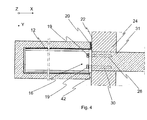
- Fig. 4 another embodiment of the present invention is shown.
- the fixing means 16 via the tensile force reinforcing elements 26 and pressure reinforcing elements 30 is fixed directly to the ceiling plate 31, without - as in the embodiment of Fig. 1 . 2 and 3 -
- the further decoupling means 20 is between the portion of the balcony slab 2, which covers the carrier element 4 and the further building part 24 arranged or formed and consists of a DämmstMail.
- the formed below the support member 4 portion of the balcony slab 2 is spaced in the longitudinal direction X of the other building part 24, whereby an intermediate region 42 is formed. Due to the intermediate region 42, the elastomer plate 12 and the insulating strip 20, the balcony plate 2 is spaced from the carrier element 4, the fixing device 16 and the further building part 24, whereby sound bridges are avoided.
- a force distribution plate 44 is arranged in sections between the insulation board 20 and the ceiling plate 31, through which the reinforcing elements 26, 30 extend therethrough.
- a connecting elements 46, 48 is arranged on each reinforcing element 26, 30.
- the fixing plate 17 connecting elements 19 are provided on both sides.
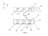
- Fig. 6a a further embodiment is shown in which three carrier elements 4 are coupled to a balcony plate 2.
- the projecting building part 2 surrounds the support elements 4 while the top side and laterally along the longitudinal direction X, but not also below, which especially simplifies the installation of the balcony slab in that the balcony slab 2 can be placed on the plurality of support elements 4 from above.
- Fig. 6b is in demarcation hereof in Fig. 2 shown representation again schematically, according to which a bottom-side enclosure 50 of the support member 4 is provided by the balcony slab 2.
- the assembly takes place in that the balcony plate threaded onto the support elements and along the support elements in the direction of the building (ie in Fig. 6b in the X direction).
- Fig. 7 is also a schematic representation shown. From this representation, it can be seen that the balcony slab 2 is also formed exclusively above the vibration decoupling means 12, ie, it can simply be placed on the carrier elements 4.
- the present invention has the significant advantage of providing vibration isolation for cantilever components by simple means.
Landscapes
- Engineering & Computer Science (AREA)
- Architecture (AREA)
- Physics & Mathematics (AREA)
- Electromagnetism (AREA)
- Civil Engineering (AREA)
- Structural Engineering (AREA)
- Buildings Adapted To Withstand Abnormal External Influences (AREA)
- Vibration Prevention Devices (AREA)
Applications Claiming Priority (1)
| Application Number | Priority Date | Filing Date | Title |
|---|---|---|---|
| DE201210013489 DE102012013489A1 (de) | 2012-07-09 | 2012-07-09 | Vorrichtung zum schwingungsentkoppelten Auflagern eines auskragenden Gebäudeteils |
Publications (2)
| Publication Number | Publication Date |
|---|---|
| EP2685018A2 true EP2685018A2 (fr) | 2014-01-15 |
| EP2685018A3 EP2685018A3 (fr) | 2014-03-05 |
Family
ID=48746285
Family Applications (1)
| Application Number | Title | Priority Date | Filing Date |
|---|---|---|---|
| EP13173709.0A Withdrawn EP2685018A3 (fr) | 2012-07-09 | 2013-06-26 | Dispositif de logement à découplage d'oscillations d'une partie de bâtiment en porte-à-faux |
Country Status (2)
| Country | Link |
|---|---|
| EP (1) | EP2685018A3 (fr) |
| DE (1) | DE102012013489A1 (fr) |
Cited By (1)
| Publication number | Priority date | Publication date | Assignee | Title |
|---|---|---|---|---|
| WO2017086777A1 (fr) * | 2015-11-16 | 2017-05-26 | T&R Engineering B.V. | Bâtiment et balcon |
Families Citing this family (2)
| Publication number | Priority date | Publication date | Assignee | Title |
|---|---|---|---|---|
| DE102019133999A1 (de) * | 2019-12-11 | 2021-06-17 | Max Frank Gmbh & Co. Kg | Anordnung zum Verbinden eines Bauwerkteils mit einem dem Bauwerkteil vorgelagerten Außenteil |
| DE102019133997A1 (de) * | 2019-12-11 | 2021-06-17 | Max Frank Gmbh & Co. Kg | Anordnung zum Verbinden eines Bauwerkteils mit einem dem Bauwerkteil vorgelagerten Außenteil |
Family Cites Families (6)
| Publication number | Priority date | Publication date | Assignee | Title |
|---|---|---|---|---|
| DE3933594A1 (de) * | 1989-10-07 | 1991-04-11 | Hilary Weinberg | Balkon |
| SE466507B (sv) * | 1991-02-01 | 1992-02-24 | Hill Arne Ab | Foerfarande och anordning foer infaestning av balkong eller liknande vid betongbjaelklag |
| DE19908388B4 (de) * | 1999-02-26 | 2008-10-30 | Schöck Bauteile GmbH | Bauelement zur Wärmedämmung |
| DE102004041289A1 (de) * | 2004-08-25 | 2006-03-09 | Brandenburgische Technische Universität Cottbus | Anordnung zur mechanischen Verbindung von lasttragenden Strukturen |
| DE202007012823U1 (de) * | 2007-09-13 | 2009-02-05 | H-Bau Technik Gmbh | Bauteilanschluss |
| DE202007017679U1 (de) * | 2007-12-18 | 2008-03-06 | Kröger, Claus | Anbauanordnung für von Baukörpern auskragende Konstruktionen |
-
2012
- 2012-07-09 DE DE201210013489 patent/DE102012013489A1/de not_active Withdrawn
-
2013
- 2013-06-26 EP EP13173709.0A patent/EP2685018A3/fr not_active Withdrawn
Non-Patent Citations (1)
| Title |
|---|
| None |
Cited By (2)
| Publication number | Priority date | Publication date | Assignee | Title |
|---|---|---|---|---|
| WO2017086777A1 (fr) * | 2015-11-16 | 2017-05-26 | T&R Engineering B.V. | Bâtiment et balcon |
| NL2017754A (nl) * | 2015-11-16 | 2017-06-02 | T&R Eng B V | Gebouw en gevelelement |
Also Published As
| Publication number | Publication date |
|---|---|
| EP2685018A3 (fr) | 2014-03-05 |
| DE102012013489A1 (de) | 2014-05-08 |
Similar Documents
| Publication | Publication Date | Title |
|---|---|---|
| EP1832690B1 (fr) | Elément de construction pour isolation thermique | |
| EP2446096B1 (fr) | Support d`angle pour système de façade | |
| EP2138641A2 (fr) | Elément de construction destiné à l'isolation thermique et matériau d'isolation pour le domaine de la construction | |
| DE60127504T2 (de) | Grundelement für die einrichtung eines thermischen unterbrechers zwischen einer wand und einer betonplatte und gebäudestruktur mit entsprechender anwendung | |
| EP2754766B1 (fr) | Dispositif permettant de relier, avec transmission de forces, une première partie porteuse d'un bâtiment à une seconde partie portée du bâtiment | |
| DE102012013489A1 (de) | Vorrichtung zum schwingungsentkoppelten Auflagern eines auskragenden Gebäudeteils | |
| DE102013223292A1 (de) | Beabstandungsvorrichtung | |
| DE19543768A1 (de) | Balkonanschluß | |
| EP1722037B1 (fr) | Dispositif de guidage de la circulation | |
| EP3754125B1 (fr) | Élément de construction pour le montage dans des joints de dilatation de bâtiments | |
| EP4026958A2 (fr) | Dispositif permettant de relier par transfert de force une première partie porteuse de bâtiment à une seconde partie portée de bâtiment | |
| EP2339071A1 (fr) | Elément de liaison et élément de délimitation de voies de circulation | |
| DE102016106036A1 (de) | Anschlussbauteil zur Wärmeentkopplung zwischen einem vertikalen und einem horizontalen Gebäudeteil | |
| EP2607560B1 (fr) | Élément de raccordement de dalle | |
| EP2898158A1 (fr) | Elément de fixation pour un dispositif de sécurité | |
| DE202017107261U1 (de) | Betonfertigteil mit mindestens einem eine Last aufnehmenden Bauteil | |
| EP4050170B1 (fr) | Construction pourvue d'élément thermoisolant | |
| DE202013104418U1 (de) | Fassadenkonsole sowie Fassadenkonstruktion | |
| WO2014028956A1 (fr) | Système de retenue et structure de transition entre deux systèmes de retenue de véhicules présentant des rigidités latérales différentes | |
| EP3015612B1 (fr) | Élement de mur d'une construction ayant deux profiles et une plaque de mousse | |
| EP4299861A1 (fr) | Dispositif et procédé de renforcement ultérieur d'un composant doté d'au moins une zone de discontinuité | |
| AT512794B1 (de) | Vorrichtung zum Energieabbau und zur Zugkraftkontrolle in Seilkonstruktionen, insbesondere für Steinschlagschutz-, Murgang- und Lawinenverbauungen | |
| AT513450B1 (de) | Befestigungselement für eine Sicherheitseinrichtung | |
| WO2010083998A2 (fr) | Ancre de fixation destinée à la fixation d'une façade | |
| CH697248B1 (de) | Schallschutzelement und Schallschutzwand. |
Legal Events
| Date | Code | Title | Description |
|---|---|---|---|
| PUAI | Public reference made under article 153(3) epc to a published international application that has entered the european phase |
Free format text: ORIGINAL CODE: 0009012 |
|
| AK | Designated contracting states |
Kind code of ref document: A2 Designated state(s): AL AT BE BG CH CY CZ DE DK EE ES FI FR GB GR HR HU IE IS IT LI LT LU LV MC MK MT NL NO PL PT RO RS SE SI SK SM TR |
|
| AX | Request for extension of the european patent |
Extension state: BA ME |
|
| PUAL | Search report despatched |
Free format text: ORIGINAL CODE: 0009013 |
|
| AK | Designated contracting states |
Kind code of ref document: A3 Designated state(s): AL AT BE BG CH CY CZ DE DK EE ES FI FR GB GR HR HU IE IS IT LI LT LU LV MC MK MT NL NO PL PT RO RS SE SI SK SM TR |
|
| AX | Request for extension of the european patent |
Extension state: BA ME |
|
| RIC1 | Information provided on ipc code assigned before grant |
Ipc: E04B 1/00 20060101AFI20140128BHEP |
|
| STAA | Information on the status of an ep patent application or granted ep patent |
Free format text: STATUS: THE APPLICATION IS DEEMED TO BE WITHDRAWN |
|
| 18D | Application deemed to be withdrawn |
Effective date: 20140906 |