EP2696008A2 - Echafaudage télescopable et procédé de fonctionnement d'un échafaudage télescopable - Google Patents
Echafaudage télescopable et procédé de fonctionnement d'un échafaudage télescopable Download PDFInfo
- Publication number
- EP2696008A2 EP2696008A2 EP12008523.8A EP12008523A EP2696008A2 EP 2696008 A2 EP2696008 A2 EP 2696008A2 EP 12008523 A EP12008523 A EP 12008523A EP 2696008 A2 EP2696008 A2 EP 2696008A2
- Authority
- EP
- European Patent Office
- Prior art keywords
- frame part
- scaffold
- parts
- scaffolding
- cables
- Prior art date
- Legal status (The legal status is an assumption and is not a legal conclusion. Google has not performed a legal analysis and makes no representation as to the accuracy of the status listed.)
- Withdrawn
Links
- 238000000034 method Methods 0.000 title claims abstract description 8
- 238000006073 displacement reaction Methods 0.000 claims abstract description 22
- 210000000078 claw Anatomy 0.000 claims description 6
- 239000002184 metal Substances 0.000 claims description 5
- 239000000463 material Substances 0.000 description 2
- 235000003332 Ilex aquifolium Nutrition 0.000 description 1
- 241000209027 Ilex aquifolium Species 0.000 description 1
- 238000010276 construction Methods 0.000 description 1
Images




Classifications
-
- E—FIXED CONSTRUCTIONS
- E04—BUILDING
- E04G—SCAFFOLDING; FORMS; SHUTTERING; BUILDING IMPLEMENTS OR AIDS, OR THEIR USE; HANDLING BUILDING MATERIALS ON THE SITE; REPAIRING, BREAKING-UP OR OTHER WORK ON EXISTING BUILDINGS
- E04G1/00—Scaffolds primarily resting on the ground
- E04G1/18—Scaffolds primarily resting on the ground adjustable in height
- E04G1/22—Scaffolds having a platform on an extensible substructure, e.g. of telescopic type or with lazy-tongs mechanism
-
- E—FIXED CONSTRUCTIONS
- E04—BUILDING
- E04G—SCAFFOLDING; FORMS; SHUTTERING; BUILDING IMPLEMENTS OR AIDS, OR THEIR USE; HANDLING BUILDING MATERIALS ON THE SITE; REPAIRING, BREAKING-UP OR OTHER WORK ON EXISTING BUILDINGS
- E04G1/00—Scaffolds primarily resting on the ground
- E04G1/28—Scaffolds primarily resting on the ground designed to provide support only at a low height
- E04G1/30—Ladder scaffolds
-
- E—FIXED CONSTRUCTIONS
- E04—BUILDING
- E04G—SCAFFOLDING; FORMS; SHUTTERING; BUILDING IMPLEMENTS OR AIDS, OR THEIR USE; HANDLING BUILDING MATERIALS ON THE SITE; REPAIRING, BREAKING-UP OR OTHER WORK ON EXISTING BUILDINGS
- E04G1/00—Scaffolds primarily resting on the ground
- E04G1/24—Scaffolds primarily resting on the ground comprising essentially special base constructions; comprising essentially special ground-engaging parts, e.g. inclined struts, wheels
- E04G2001/248—Inclined struts
-
- E—FIXED CONSTRUCTIONS
- E04—BUILDING
- E04G—SCAFFOLDING; FORMS; SHUTTERING; BUILDING IMPLEMENTS OR AIDS, OR THEIR USE; HANDLING BUILDING MATERIALS ON THE SITE; REPAIRING, BREAKING-UP OR OTHER WORK ON EXISTING BUILDINGS
- E04G1/00—Scaffolds primarily resting on the ground
- E04G1/28—Scaffolds primarily resting on the ground designed to provide support only at a low height
- E04G1/30—Ladder scaffolds
- E04G2001/302—Ladder scaffolds with ladders supporting the platform
- E04G2001/305—The ladders being vertical and perpendicular to the platform
Definitions
- the invention relates to a telescopic work scaffold according to the preamble of patent claim 1.
- Such a telescopic working scaffold has become known, for example, with an embodiment of the type Z600 ZAP from Zarges.
- Characteristic of this known work scaffold is that at least two heights are adjustable and mutually displaceable in the vertical direction scaffolding parts are available, each of which scaffold part consists of mutually parallel and mutually spaced, vertical ladder parts whose vertical spars are connected by rungs.
- the height adjustment of the known work scaffold is difficult and expensive.
- the height adjustment takes place after a self-arresting extension ladder principle. This means that in the height adjustment between the bottom-side frame part and the base frame part slidably disposed inner frame part, the operator first raises on one side of the frame part to elevate the inner frame part obliquely against the bottom-side frame part until it reaches a certain rung on the bottom side Skeleton part latches.
- the invention is characterized by the technical teaching of claim 1.
- a method for easy operation of such a work scaffold is the subject of independent claim 8.
- An essential feature of the invention is that now no longer a canting of the inner frame part in relation to the outer frame part is necessary, and consequently no longer a self-arresting extension ladder principle is used for height adjustment, but that instead the operation of the displacement of the individual frame parts to each other via cables.
- the invention therefore requires the operation of the scaffolding parts by cables, but it is not necessary for the solution that such a cable actually consists of a rope. It can also consist of a chain or a combination of rope and chain links.
- the cables are manually operated.
- the invention is not limited thereto.
- the cables are driven by a motor. This requires that the respective cable (or chain hoist) runs over a cable drum, which is driven by a motor.
- the telescopic work scaffold consists of at least two telescopically guided scaffolding parts.
- the work scaffold consists of a total of three mutually displaceable scaffolding parts, namely a bottom-side frame part, a slidably and detectably received in this bottom-side frame part, middle frame part, and slidably received from a detectable in the middle frame part and detectable upper frame part.
- two cables are provided at least for each frame part, which are each actuated together.
- the shift takes place in such a way that, initially, in a first method step, the frame part is moved vertically upwards in the area of the middle frame part, and when this position is reached, in the second method step, the middle frame part (which carries the upper frame part in the pushed out position) are pushed out of the bottom frame part.
- the cables are thus present in pairs, and each pair is used for parallel displacement of each of these cable pair associated scaffolding.
- the cables of each pair are thus also changed synchronously in their length in order to achieve a parallel guidance of this pair of cables associated scaffolding.
- a sliding ladder with locking device is also also due to the originating from the same applicant DE 297 13 340 U1 known.
- This automatically acting locking device is the subject of the present invention.
- the description after the DE 297 13 340 U1 is intended to be fully encompassed by the disclosure of the present invention.
- a scaffold in general is from the originating from the same applicant European patent application EP 1 000 94 70 become known, but can also be done by others and by individual struts. There is also described a side railing for a scaffolding, which is also used in the present scaffolding.
- the struts used in the work scaffold according to the invention are, for example, the subject of going back to the same applicant DE 197 07 799 B ,
- a working scaffold consisting of three scaffolding parts 1, 2, 3 is generally shown, although the invention could also have only two scaffolding parts which can be displaced relative to one another.
- the upper frame part 3 could be omitted and the upper frame part 2 could be arranged directly telescopically in the lower frame part 1.
- the scaffold has in a conventional manner on the bottom side boom 4, the subject of the DE 197 07 799 B are.
- a working platform 5 is mounted, and also two opposing side railing 6 are mounted, the subject of the EP 1 000 94 70 are, or without side panels.
- Each frame part 1, 2, 3 consists of two mutually in the vertical and parallel spaced apart frame parts 30, each of which ladder part 30 is connected by rungs 31 with each other.
- the scaffold shown here consisting of three scaffolding parts 1, 2, 3 could therefore also be referred to as a ladder frame.
- the cables 7, 10 are therefore arranged in pairs and should be operated almost synchronously.
- FIG. 2 shows the scaffolding after FIG. 1 in another perspective, namely in the plan view of the suspended on the upper frame part 3 working platform 5. It is still recognizable that at least the lower frame part 1 is stabilized by transverse struts 32 without jamming.
- each case hook according to FIG. 4 consists of a spring-loaded claw 15 which rests against the rung 31 of the opposite frame part 30. This is in FIG. 4 shown.
- the hooks 11, 12 are each arranged with its base plate on the inside of the spar of a scaffolding part and are based with their spring-loaded claw 15 on the rung 31 of the opposite frame part 30 from.
- FIG. 4 is shown as an example that initially moves the upper frame part 3 by operation of the cables 9, 10 from the middle frame part 2 out, wherein the middle frame part 2 still fully inserted in the lower frame part 1 remains.
- the cable 9 is guided over pulleys 14 at the upper spar of the middle frame part 2 and spans the entire width of the work frame, where it is again guided on the opposite side via pulleys 14 to a downwardly directed attachment point 19.
- This attachment point 19 is attached to the lower end of the spar 23 of the upper frame part 3.
- the spring-loaded jaws 15 By the lifting movement of the upper frame part 3 to the middle frame part 2, the spring-loaded jaws 15 get out of engagement with the respective rung 31, automatically snap back into their base and are spring loaded again brought into their engagement position, as soon as they with a new, overlying rung 31st get in touch.
- the same displacement movement takes place during the displacement of the middle frame part 2 from the stationary, lower frame part 1.
- the cables 7, 8 are provided, and these cables are the associated with respective deflection rollers 13, which are arranged on the upper sides of the spars 21 of the lower frame part 1.
- FIG. 5 shows further details of the sliding movement, wherein it is also shown that the respective claw 15 of the drop hook 11, 12 has a pivot axis 16.
- the cable 7 is thus associated with the attachment point 17, the cable 8 of the attachment point 18 and the cable 9 of the attachment point 19 and the cable 10 of the attachment point 20th
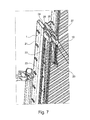
- FIGS. 6 and 7 now show the longitudinal guide elements, which are necessary to the scaffolding parts 1, 2, 3 to deliver slidably and parallel to each other without jamming.
- FIG. 6 shows the FIG. 6 in that arranged on the inside of the spar 21 of the lower frame part 1 is a sheet-metal tab 24 which laterally projects over the rail profile, wherein at its inner end a guide piece 26 is arranged, which preferably consists of a plastic material.
- the sheet metal tab 25 which is arranged on the middle frame part 2 and which also carries an inwardly directed guide piece 27 - preferably made of a plastic material - carries.
- the guide pieces 26, 27 each engage in an outwardly directed longitudinal groove 28, 29 on the respective bar 22, 23 a.
- FIG. 6 shows that the deflection rollers 13, 14 can be arranged in pairs.
- FIG. 7 shows that the pulleys 13, 14 but can only be arranged individually.
- FIG. 8 shows the longitudinal displacement of the central frame part 2 with respect to the fixed, lower frame part 1 with said guide pieces 26, 27th
- FIG. 10 shows as a further embodiment that it is not necessary for the solution that each paired cables must be provided on one side of the scaffolding.
- FIG. 10 shows that in the presence of two operators it is possible for one operator to operate the cables 7, 9 while the other operator operates the cables 8, 10.
- the upper frame part 3 is pushed out of the middle frame part 2 by actuation of the cables 9, 10, and if the upper frame part 3 is anchored in the desired height adjustment in the middle frame part 2 by automatic locking of the hooks 11 are of two different operators operated the cables 7 and 8, so as to push out the middle frame part 2 from the lower frame part 1.
Landscapes
- Engineering & Computer Science (AREA)
- Architecture (AREA)
- Mechanical Engineering (AREA)
- Civil Engineering (AREA)
- Structural Engineering (AREA)
- Ladders (AREA)
- Movable Scaffolding (AREA)
Applications Claiming Priority (1)
| Application Number | Priority Date | Filing Date | Title |
|---|---|---|---|
| DE102012015987.0A DE102012015987A1 (de) | 2012-08-11 | 2012-08-11 | Teleskopierbares Arbeitsgerüst und Verfahren zum Betrieb eines teleskopierbaren Arbeitsgerüstes |
Publications (2)
| Publication Number | Publication Date |
|---|---|
| EP2696008A2 true EP2696008A2 (fr) | 2014-02-12 |
| EP2696008A3 EP2696008A3 (fr) | 2014-11-19 |
Family
ID=47602740
Family Applications (1)
| Application Number | Title | Priority Date | Filing Date |
|---|---|---|---|
| EP12008523.8A Withdrawn EP2696008A3 (fr) | 2012-08-11 | 2012-12-21 | Echafaudage télescopable et procédé de fonctionnement d'un échafaudage télescopable |
Country Status (2)
| Country | Link |
|---|---|
| EP (1) | EP2696008A3 (fr) |
| DE (1) | DE102012015987A1 (fr) |
Cited By (6)
| Publication number | Priority date | Publication date | Assignee | Title |
|---|---|---|---|---|
| GB2544623A (en) * | 2015-11-12 | 2017-05-24 | Ability Int Ltd | Apparatus for enabling a person to work at an elevated position in confined surroundings |
| CN111691656A (zh) * | 2020-07-14 | 2020-09-22 | 陕西国防工业职业技术学院 | 建筑施工架及其制造方法 |
| CN111877721A (zh) * | 2020-08-10 | 2020-11-03 | 南京工程学院 | 一种具有防护功能的装配式建筑外墙施工用升降架 |
| CN115522719A (zh) * | 2022-09-27 | 2022-12-27 | 广东韶钢工程技术有限公司 | 一种工业厂房幕墙安装工装及使用方法 |
| FR3166649A1 (fr) | 2024-09-26 | 2026-03-27 | Duarib Group | Bras articulé pour échafaudage, en particulier pour garde-corps |
| FR3166648A1 (fr) | 2024-09-26 | 2026-03-27 | Duarib Group | Echafaudage roulant à échelles pivotantes et réglables en hauteur |
Families Citing this family (1)
| Publication number | Priority date | Publication date | Assignee | Title |
|---|---|---|---|---|
| CN111962957A (zh) * | 2020-08-18 | 2020-11-20 | 广东电网有限责任公司肇庆供电局 | 一种电力线路钢管杆架设用组装工具 |
Citations (4)
| Publication number | Priority date | Publication date | Assignee | Title |
|---|---|---|---|---|
| DE2507888C3 (de) | 1975-02-24 | 1978-09-07 | Hymer Leichtmetallbau Ing. Erwin Hymer, 7988 Wangen | Feststellvorrichtung zur gegenseitigen lösbaren Verrastung der Leiterteile einer mindestens zweiteiligen Schiebeleiter |
| DE29713340U1 (de) | 1997-07-26 | 1998-04-16 | Hymer Leichtmetallbau Gmbh & C | Schiebeleiter mit Seilzug und Sperreinrichtung |
| EP1000947A2 (fr) | 1998-11-10 | 2000-05-17 | Sharp Kabushiki Kaisha | Précurseurs à base d'éthylène contenant un métal, et leur préparation |
| DE19707799B4 (de) | 1997-02-27 | 2010-01-28 | Hymer-Leichtmetallbau Gmbh & Co. Kg | Arbeitsgerüst mit heb- und senkbarem Ausleger |
Family Cites Families (12)
| Publication number | Priority date | Publication date | Assignee | Title |
|---|---|---|---|---|
| DE921172C (de) * | 1949-01-19 | 1954-12-09 | Richard Gladewitz | Fahrbares, ausziehbares Leitergeruest |
| FR1302912A (fr) * | 1958-07-01 | 1962-09-07 | échafaudage mobile à éléments télescopiques | |
| FR2312623A1 (fr) * | 1975-05-28 | 1976-12-24 | Gubri Sa Ets L | Perfectionnements apportes aux ensembles du genre des echafaudages |
| FR2428733A1 (fr) * | 1978-06-12 | 1980-01-11 | Genries Pierre | Echelle coulissante |
| FR2648508A1 (fr) * | 1989-06-14 | 1990-12-21 | Gubri Michel | Echelle a coulisse |
| GB2262931A (en) * | 1992-01-02 | 1993-07-07 | John Arthur Roake | Extendable tower. |
| DE29619314U1 (de) * | 1996-11-07 | 1997-01-02 | Ludwig, Günter, 50259 Pulheim | Gerüst |
| DE19912050A1 (de) * | 1999-03-18 | 2000-10-05 | Monotal Schornsteinbau Gmbh | Montagegerüst mit einer in der Höhe verstellbaren Bühne |
| DE20315839U1 (de) * | 2003-10-15 | 2003-12-18 | Hailo-Werk Rudolf Loh Gmbh & Co. Kg | Baugerüst |
| GB0512597D0 (en) * | 2005-06-21 | 2005-07-27 | Ad & C Ltd | Climbing guard rail protection system for scaffolding towers |
| DE102009041437A1 (de) * | 2009-09-16 | 2011-03-24 | Hymer-Leichtmetallbau Gmbh & Co. Kg | Seitenschutzgeländer für ein Arbeitsgerüst |
| DE102009049869A1 (de) * | 2009-10-20 | 2011-04-28 | Hymer-Leichtmetallbau Gmbh & Co. Kg | Arbeitskorb für eine Leiter |
-
2012
- 2012-08-11 DE DE102012015987.0A patent/DE102012015987A1/de not_active Withdrawn
- 2012-12-21 EP EP12008523.8A patent/EP2696008A3/fr not_active Withdrawn
Patent Citations (4)
| Publication number | Priority date | Publication date | Assignee | Title |
|---|---|---|---|---|
| DE2507888C3 (de) | 1975-02-24 | 1978-09-07 | Hymer Leichtmetallbau Ing. Erwin Hymer, 7988 Wangen | Feststellvorrichtung zur gegenseitigen lösbaren Verrastung der Leiterteile einer mindestens zweiteiligen Schiebeleiter |
| DE19707799B4 (de) | 1997-02-27 | 2010-01-28 | Hymer-Leichtmetallbau Gmbh & Co. Kg | Arbeitsgerüst mit heb- und senkbarem Ausleger |
| DE29713340U1 (de) | 1997-07-26 | 1998-04-16 | Hymer Leichtmetallbau Gmbh & C | Schiebeleiter mit Seilzug und Sperreinrichtung |
| EP1000947A2 (fr) | 1998-11-10 | 2000-05-17 | Sharp Kabushiki Kaisha | Précurseurs à base d'éthylène contenant un métal, et leur préparation |
Cited By (8)
| Publication number | Priority date | Publication date | Assignee | Title |
|---|---|---|---|---|
| GB2544623A (en) * | 2015-11-12 | 2017-05-24 | Ability Int Ltd | Apparatus for enabling a person to work at an elevated position in confined surroundings |
| GB2544623B (en) * | 2015-11-12 | 2021-05-26 | Ability International Ltd | Apparatus for enabling a person to work at an elevated position in confined surroundings |
| CN111691656A (zh) * | 2020-07-14 | 2020-09-22 | 陕西国防工业职业技术学院 | 建筑施工架及其制造方法 |
| CN111877721A (zh) * | 2020-08-10 | 2020-11-03 | 南京工程学院 | 一种具有防护功能的装配式建筑外墙施工用升降架 |
| CN115522719A (zh) * | 2022-09-27 | 2022-12-27 | 广东韶钢工程技术有限公司 | 一种工业厂房幕墙安装工装及使用方法 |
| FR3166649A1 (fr) | 2024-09-26 | 2026-03-27 | Duarib Group | Bras articulé pour échafaudage, en particulier pour garde-corps |
| FR3166648A1 (fr) | 2024-09-26 | 2026-03-27 | Duarib Group | Echafaudage roulant à échelles pivotantes et réglables en hauteur |
| WO2026068558A1 (fr) | 2024-09-26 | 2026-04-02 | Duarib Group | Échafaudage roulant à échelles pivotantes et réglables en hauteur |
Also Published As
| Publication number | Publication date |
|---|---|
| EP2696008A3 (fr) | 2014-11-19 |
| DE102012015987A1 (de) | 2014-02-13 |
Similar Documents
| Publication | Publication Date | Title |
|---|---|---|
| DE69408453T2 (de) | Höhenverstellbare Arbeitsvorrichtung | |
| EP2696008A2 (fr) | Echafaudage télescopable et procédé de fonctionnement d'un échafaudage télescopable | |
| DE3025017C2 (fr) | ||
| DE102008050178A1 (de) | Arbeitsgerüst | |
| DE29908954U1 (de) | Arbeitsplattform, insbesondere bei Arbeitsbühnen oder Baugerüsten | |
| EP2631390A2 (fr) | Dispositif de sécurité et de levage pour un échafaudage-échelle et échafaudage-échelle de sécurité et de levage | |
| DE3151986C2 (de) | Vorrichtung zum Führen und Verstellen der Höhe einer Tischplatte | |
| DE112021002851T5 (de) | Sicherheitsleiter | |
| DE3509833C1 (de) | Hebebühne | |
| EP1571083B1 (fr) | Dispositif de levage avec une échelle et son utilisation | |
| DE1554472B1 (de) | Vorrichtung an Regalen od.dgl. zum leicht loesbaren Verbinden eines Pfostens mit einem Tragstueck | |
| DE102005025802A1 (de) | Hubvorrichtung und Hubsystem | |
| DE29613678U1 (de) | Führungsvorrichtung für eine Energieführungskette | |
| DE2706108C2 (de) | Verfahren und Einrichtung zur Lageänderung beweglicher Abschnitte in Bühnenböden | |
| WO1998027308A1 (fr) | Echelle telescopique | |
| DE202022102552U1 (de) | Leiter | |
| DE3630304C1 (en) | Vertically adjustable podium | |
| DE9112423U1 (de) | Metallstandgerüst | |
| DE2337892C2 (de) | Arbeitsgerüst mit heb- und senkbarer Arbeitsbühne | |
| AT506243B1 (de) | Aufsteigvorrichtung | |
| AT403035B (de) | Entlang des mastes eines aufzuges verfahrbare lastbühne | |
| DE1126094B (de) | Baukran od. dgl. | |
| DE2312994A1 (de) | Fahrbares arbeitsgeruest von verstellbarer hoehe | |
| DE1281668B (de) | Zerlegbares, fahrbares Arbeitsgeruest | |
| DE3625086A1 (de) | Vorrichtung zur vergroesserung der hubhoehe des lasttraegers eines regalstapelfahrzeuges |
Legal Events
| Date | Code | Title | Description |
|---|---|---|---|
| AK | Designated contracting states |
Kind code of ref document: A2 Designated state(s): AL AT BE BG CH CY CZ DE DK EE ES FI FR GB GR HR HU IE IS IT LI LT LU LV MC MK MT NL NO PL PT RO RS SE SI SK SM TR |
|
| AX | Request for extension of the european patent |
Extension state: BA ME |
|
| PUAI | Public reference made under article 153(3) epc to a published international application that has entered the european phase |
Free format text: ORIGINAL CODE: 0009012 |
|
| PUAL | Search report despatched |
Free format text: ORIGINAL CODE: 0009013 |
|
| AK | Designated contracting states |
Kind code of ref document: A3 Designated state(s): AL AT BE BG CH CY CZ DE DK EE ES FI FR GB GR HR HU IE IS IT LI LT LU LV MC MK MT NL NO PL PT RO RS SE SI SK SM TR |
|
| AX | Request for extension of the european patent |
Extension state: BA ME |
|
| RIC1 | Information provided on ipc code assigned before grant |
Ipc: E04G 1/22 20060101AFI20141015BHEP Ipc: E04G 1/30 20060101ALI20141015BHEP |
|
| STAA | Information on the status of an ep patent application or granted ep patent |
Free format text: STATUS: THE APPLICATION IS DEEMED TO BE WITHDRAWN |
|
| 18D | Application deemed to be withdrawn |
Effective date: 20150520 |