EP2726246B1 - Tête de traitement laser comportant un élément optique - Google Patents
Tête de traitement laser comportant un élément optique Download PDFInfo
- Publication number
- EP2726246B1 EP2726246B1 EP12728208.5A EP12728208A EP2726246B1 EP 2726246 B1 EP2726246 B1 EP 2726246B1 EP 12728208 A EP12728208 A EP 12728208A EP 2726246 B1 EP2726246 B1 EP 2726246B1
- Authority
- EP
- European Patent Office
- Prior art keywords
- optical element
- transponder
- laser processing
- processing head
- head according
- Prior art date
- Legal status (The legal status is an assumption and is not a legal conclusion. Google has not performed a legal analysis and makes no representation as to the accuracy of the status listed.)
- Active
Links
Images

Classifications
-
- B—PERFORMING OPERATIONS; TRANSPORTING
- B23—MACHINE TOOLS; METAL-WORKING NOT OTHERWISE PROVIDED FOR
- B23K—SOLDERING OR UNSOLDERING; WELDING; CLADDING OR PLATING BY SOLDERING OR WELDING; CUTTING BY APPLYING HEAT LOCALLY, e.g. FLAME CUTTING; WORKING BY LASER BEAM
- B23K26/00—Working by laser beam, e.g. welding, cutting or boring
- B23K26/70—Auxiliary operations or equipment
-
- B—PERFORMING OPERATIONS; TRANSPORTING
- B23—MACHINE TOOLS; METAL-WORKING NOT OTHERWISE PROVIDED FOR
- B23K—SOLDERING OR UNSOLDERING; WELDING; CLADDING OR PLATING BY SOLDERING OR WELDING; CUTTING BY APPLYING HEAT LOCALLY, e.g. FLAME CUTTING; WORKING BY LASER BEAM
- B23K26/00—Working by laser beam, e.g. welding, cutting or boring
- B23K26/70—Auxiliary operations or equipment
- B23K26/702—Auxiliary equipment
-
- B—PERFORMING OPERATIONS; TRANSPORTING
- B23—MACHINE TOOLS; METAL-WORKING NOT OTHERWISE PROVIDED FOR
- B23K—SOLDERING OR UNSOLDERING; WELDING; CLADDING OR PLATING BY SOLDERING OR WELDING; CUTTING BY APPLYING HEAT LOCALLY, e.g. FLAME CUTTING; WORKING BY LASER BEAM
- B23K26/00—Working by laser beam, e.g. welding, cutting or boring
- B23K26/02—Positioning or observing the workpiece, e.g. with respect to the point of impact; Aligning, aiming or focusing the laser beam
- B23K26/03—Observing, e.g. monitoring, the workpiece
-
- B—PERFORMING OPERATIONS; TRANSPORTING
- B23—MACHINE TOOLS; METAL-WORKING NOT OTHERWISE PROVIDED FOR
- B23K—SOLDERING OR UNSOLDERING; WELDING; CLADDING OR PLATING BY SOLDERING OR WELDING; CUTTING BY APPLYING HEAT LOCALLY, e.g. FLAME CUTTING; WORKING BY LASER BEAM
- B23K26/00—Working by laser beam, e.g. welding, cutting or boring
- B23K26/02—Positioning or observing the workpiece, e.g. with respect to the point of impact; Aligning, aiming or focusing the laser beam
- B23K26/06—Shaping the laser beam, e.g. by masks or multi-focusing
- B23K26/064—Shaping the laser beam, e.g. by masks or multi-focusing by means of optical elements, e.g. lenses, mirrors or prisms
-
- B—PERFORMING OPERATIONS; TRANSPORTING
- B23—MACHINE TOOLS; METAL-WORKING NOT OTHERWISE PROVIDED FOR
- B23K—SOLDERING OR UNSOLDERING; WELDING; CLADDING OR PLATING BY SOLDERING OR WELDING; CUTTING BY APPLYING HEAT LOCALLY, e.g. FLAME CUTTING; WORKING BY LASER BEAM
- B23K26/00—Working by laser beam, e.g. welding, cutting or boring
- B23K26/70—Auxiliary operations or equipment
- B23K26/702—Auxiliary equipment
- B23K26/707—Auxiliary equipment for monitoring laser beam transmission optics
Definitions
- the invention relates to a laser processing head with the features of the preamble of patent claim 1.
- a laser processing head with the features of the preamble of patent claim 1 is from WO 2006/103104 A1 known.
- Laser material processing machines have a laser processing head, which can include, among other things, at least one lens as an optical element or, in the case of YAG laser material processing machines, as an optical element in addition to lenses as an optical element and also a protective window.
- a laser processing head can include, among other things, at least one lens as an optical element or, in the case of YAG laser material processing machines, as an optical element in addition to lenses as an optical element and also a protective window.
- optical elements In the area of laser material processing, optical elements have no identification beyond a laser-marked material number and a production date.
- special problems arise when processing laser materials in the high-performance range.
- the optical elements can become dirty and/or wear out or age. It is desirable to obtain information about this and to use this information appropriately.
- the DE 10 2005 010 479 A1 discloses a device with several optical elements for insertion into a light beam, each element being able to be brought into its working position in the beam path, the elements in are provided in a magazine and can be moved from a ready position to the working position via a changing mechanism.
- the task to be solved with the present invention is to read and write information from the transponder without affecting the operation of the laser processing head.
- the transponder and the reading and/or writing device are preferably arranged opposite one another when the optical element is installed, so that they are arranged close to one another. This makes it possible for the information to be read easily and without disruption.
- the focal length can also be stored as a separate value or can be derived indirectly linked to other characteristics. This can prevent damage caused by installing the wrong focal length.
- the unique serial number which can be read from the transponder, can be used to ensure that it is an approved optical element. Here too, data can be stored and accessed directly for release.
- optical element With such an optical element, it is possible to store not only data on the installed state of the optical element, but also changing properties during use of the optical element and to take them into account during laser material processing. This is particularly advantageous for laser processing in the high-performance range, ie with powers ⁇ 1kW.
- the optical element is therefore preferably suitable for use with laser powers ⁇ 1kW.
- the optical element can be a transmissive or reflective optical element.
- it can be an optical element as such, namely without a holder, socket, housing or the like. It can therefore be an optical element in the sense of an optically active element, such as a lens, a protective window, a beam splitter, a reflector, a mirror, a filter or the like.
- an optical element in the sense of the invention can also be understood as an optically effective element with an attachment, such as a socket, holder, housing or the like.
- transmissive optical element for example, only a central area can be used optically during operation or can be detected by a laser beam, while an edge area is not detected by the laser beam or is not used optically.
- the transponder could then be arranged in the edge area without disturbing the optical properties of the optical element during operation.
- the surface of the optical element opposite the reflective side can be optically unused and not be detected by the laser beam.
- the transponder could then be arranged on this surface, in particular on the back of the optical element.
- the transponder is arranged on the optical element in such a way that it covers or shades part of the optically usable surface area.
- this covered or shaded area portion becomes an area that is optically unused and/or not detected by the laser beam during operation of the laser processing machine.
- the transponder can be written to.
- information regarding the history, in particular the life history of the optical element, regarding the degree of contamination, i.e. in particular information that changes during the period of use of the optical element can be stored in a memory of the transponder.
- a control of the laser material processing machine can, for example, register the cutting hours of an optical element, since the installed lens can always be clearly recognized even when the laser processing head is changed. Cleaning cycles and absorption history can also be saved and displayed accordingly.
- a user receives transparency about an important wearing part of his laser material processing machine.
- Particularly wear-promoting processes e.g. cutting with compressed air
- wear-promoting processes that the optical element has experienced can be identified in order to be able to make statements about the remaining service life of the optical element.
- Arranging the transponder in the area of the peripheral surface of the optical element has the advantage that little is covered by the optical element by the transponder, so that the optical properties of the optical element, such as the size of the optically usable surface of the optical element, are determined by the transponder Transponders are only slightly affected.
- a corresponding reading and/or writing device can be arranged particularly easily in a laser processing head in the area of the peripheral surface of the optical element.
- the transponder is arranged on the peripheral surface. This makes it possible for information to be transmitted from the transponder to the reading and/or writing device or in the opposite direction in the radial direction of the optical element. This means that the transmission routes are particularly short. This also means that no surface of the optical element is covered by the transponder in the transmission direction of the optical element.
- the surface in particular the peripheral surface, has a flat section, in particular a flat surface bevel or surface cut, on which the transponder is arranged.
- the transponder can be attached particularly well and reliably to a flat section; for example, it can be glued better to a flat section compared to a curved section.
- the optical element can be installed in the correct position via the flat section of the peripheral surface, for example by a holder having a corresponding flat section or being designed accordingly in another way.
- the transponder can be designed as an RFID transponder. If an RFID transponder is used, the information can be exchanged wirelessly between the transponder and the reading and/or writing device. In addition, an RFID transponder can function without its own energy supply.
- the transponder has a particularly small structure if it is made from polymers. Coupling with a reading device can occur using alternating magnetic fields of short range or using high-frequency radio waves. This means that the data can not only be transmitted, but the transponder can also be supplied with energy.
- Transmission at 500nm is important for the function of a lens sensor system. If information about the raw material source of the optical element is stored in the transponder, an improvement in accuracy is conceivable. This applies in particular to CO2 sensors. With a YAG laser, the emissivity of the optical element could instead be stored in the transponder and be a parameter to be transferred.
- An orientation aid for the correct positional installation of the optical element can be provided on the holder for the optical element.
- the orientation aid can interact with a flat section on the circumference of the optical element. This means you can use the The shape of the holder and the optical element ensures that they are installed in the correct position.
- the optical element is arranged in a high-pressure space in which a gas is arranged under high pressure during operation of the laser processing head and the reading and/or writing device is arranged in a low-pressure space is in which, during operation of the laser processing head, a gas is arranged at a lower pressure than in the high-pressure space, the high-pressure space and the low-pressure space being separated by a wall which has a non-metallic material at least in one area.
- a non-metallic material in particular a dielectric material, is provided in one area can ensure that information can be exchanged between the transponder and the reading and/or writing device. According to current general knowledge, this would not be possible if the wall were made entirely of metallic material.
- the wall can have a through opening which is closed by an element made of non-metallic material.
- the through opening can be closed by a quartz window.
- the optical element can be arranged in a lens cartridge, the wall of which has a through opening closed by an element made of non-metallic material.
- the through opening can be, for example, a hole in the wall of the lens cartridge.
- the diameter of the through opening should be the same preferably approximately correspond to an antenna diameter of the transponder. A diameter for the through opening of 6 mm has proven to be particularly advantageous.
- the through opening can be closed particularly easily by the element made of non-metallic material if it is glued in.
- Information can be stored in the transponder that allows the laser material processing machine to adjust the laser material processing process so that optimized material processing can be carried out.
- At least one of the following pieces of information can be read out as information regarding the optical element: material number, serial number, manufacturer, production date, batch number, raw material, emissivity, date of commissioning, transmission for a test wavelength.
- the duration of use of the optical element can be saved. Cleaning cycles or the number of cleanings, the absorption history, the operating hours, in particular the laser on times, the laser power and power densities and / or the operating modes of the laser, i.e. cw (continuous wave) or pulsed, can also be saved and then also read out again and displayed if necessary.
- cw continuous wave
- Corresponding data that is recorded via the laser processing machine can be transmitted to the transponder via a connection to the reading/writing device.
- the connection can be via lines as well as other means of data transmission without physical connections.
- the correct installation of the optical element is checked using the transponder. For example, if the optical element is installed upside down, the transponder may not be readable. This makes it possible to see that the optical element was not installed correctly.
- the transponder can be used to check whether it is an optical element approved for the laser processing head or the process to be carried out. This can be determined by reading the relevant information from the transponder.
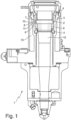
- the Figure 1 shows a longitudinal sectional view of a laser processing head 1 of a laser material processing machine designed as a laser cutting head.
- the laser processing head 1 has an optical element 2 designed as a lens. This is arranged in a lens cartridge 3, the lens cartridge 3 being exchangeable, in particular removable from the laser processing head 1.
- a threaded ring 4 is shown, which holds the lens cartridge in the laser processing head 1.
- the threaded ring 5 holds the optical element 2 via a spacer 6 in the lens cartridge 3 and thus in the laser processing head 1.
- a transponder 7 designed as an RFID label is arranged on the optical element 2. This is located opposite a reading and/or writing device 8. Through the reading and/or writing device 8, information can be read from the transponder 7 and, in some cases, information can also be written into the transponder 7.
- the reading and/or writing device 8 is connected to a control of the laser material processing machine, not shown here.
- the wall 9 of the lens cartridge 3 has a through opening 10 which is closed by an element 11 made of non-metallic material.
- the element 11 made of non-metallic material separates a high-pressure space 12, in which the optical element 2 is arranged, from a low-pressure space 13, in which the reading and/or writing device 8 is arranged.
- the wall 9 is made of a metallic material
- the element 11 is made of a non-metallic material, in particular a dielectric material, such as quartz, plastic, or ceramic. This enables an exchange of information between the transponder 7 and the reading and/or writing device 8, which would not be possible if the wall 9 were made entirely of metallic material.
- the diameter of the element 11 is larger than the diameter of the through opening 10.
- the element 11 can have a diameter of approximately 8 mm, while the through opening 10 preferably has a diameter of 6 mm.
- the size of the through opening 10 is largely determined by the size of an antenna of the transponder 7.
- the Figure 3 shows a sectional view along line III-III of Figure 2 .
- the optical element 2 has a flat peripheral surface in a section 15.
- the transponder 7 is arranged on this flat peripheral surface in section 15.
- the transponder 7 is provided in a recess 16 of the holder 17 for the optical element 2.
- the recess 16 thereby provides an orientation aid for the installation of the optical element 2.
- the through opening 10, the element 11 and the reading and/or writing device 8 can also be seen.
Landscapes
- Engineering & Computer Science (AREA)
- Physics & Mathematics (AREA)
- Optics & Photonics (AREA)
- Plasma & Fusion (AREA)
- Mechanical Engineering (AREA)
- Laser Beam Processing (AREA)
Claims (11)
- Tête d'usinage laser (1) munie d'un élément optique présentant un transpondeur (7) et d'un support (17) pour l'élément optique (2), caractérisée en ce que le transpondeur (7) contient des informations lisibles concernant l'élément optique (2), et en ce que l'élément optique présente une surface optiquement inutilisée en fonctionnement et/ou non détectée par le faisceau laser, le transpondeur (7) étant disposé dans la zone de cette surface et la tête d'usinage laser (1) présentant un dispositif de lecture et/ou d'écriture (8) qui est associé au transpondeur (7) de l'élément optique (2).
- Tête d'usinage laser selon la revendication 1, caractérisée en ce que la surface est une surface périphérique de l'élément optique (2).
- Tête d'usinage laser selon la revendication 2, caractérisée en ce que le transpondeur (7) est disposé sur la surface périphérique.
- Tête d'usinage laser selon l'une des revendications précédentes, caractérisée en ce que la surface, en particulier la surface périphérique, présente une section plane (15), en particulier un chanfrein de surface plan ou une entaille de surface plane, sur lequel ou laquelle est disposé le transpondeur (7).
- Tête d'usinage laser selon l'une des revendications précédentes, caractérisée en ce qu'une information concernant l'historique et/ou l'état de l'élément optique (2) est enregistrée dans le transpondeur (7).
- Tête d'usinage laser selon l'une des revendications précédentes, caractérisée en ce que le transpondeur (7) est conçu comme un transpondeur RFID.
- Tête d'usinage laser selon l'une des revendications précédentes, caractérisée en ce qu'il est prévu sur le support (17) pour l'élément optique (2) une aide à l'orientation pour le montage en position correcte de l'élément optique (2).
- Tête d'usinage laser selon l'une des revendications précédentes, caractérisée en ce que l'élément optique (2) est disposé dans une chambre à haute pression (12) dans laquelle, lors du fonctionnement de la tête d'usinage laser (1), un gaz à haute pression est disposé et en ce que le dispositif de lecture et/ou d'écriture (8) est disposé dans une chambre à basse pression (13) dans laquelle, pendant le fonctionnement de la tête d'usinage laser (1), un gaz est disposé à une pression plus faible que dans la chambre à haute pression (12), la chambre à haute pression (12) et la chambre à basse pression (13) étant séparées par une paroi (9) présentant, au moins dans une zone, un matériau non métallique.
- Tête d'usinage laser selon la revendication 8, caractérisée en ce que la paroi (9) présente une ouverture de passage (10) fermée par un élément (11) en matériau non métallique.
- Tête d'usinage laser selon la revendication 8 ou 9, caractérisée en ce que l'élément optique (2) est disposé dans une cartouche de lentilles (3) dont la paroi (9) présente une ouverture de passage (10) fermée par un élément (11) en matériau non métallique.
- Tête d'usinage laser selon la revendication 10, caractérisée en ce que l'élément (11) en matériau non métallique est collé dans l'ouverture de passage (10).
Priority Applications (1)
| Application Number | Priority Date | Filing Date | Title |
|---|---|---|---|
| EP20215442.3A EP3827923A1 (fr) | 2011-06-29 | 2012-06-12 | Procédé de fonctionnement d'une machine d'usinage laser de matériaux |
Applications Claiming Priority (2)
| Application Number | Priority Date | Filing Date | Title |
|---|---|---|---|
| DE102011078359A DE102011078359A1 (de) | 2011-06-29 | 2011-06-29 | Optisches Element einer Lasermaterialbearbeitungsmaschine |
| PCT/EP2012/061086 WO2013000700A1 (fr) | 2011-06-29 | 2012-06-12 | Élément optique d'une machine de traitement de matériau laser, tête de traitement laser comportant un élément optique et procédé pour faire fonctionner une machine de traitement laser |
Related Child Applications (2)
| Application Number | Title | Priority Date | Filing Date |
|---|---|---|---|
| EP20215442.3A Division-Into EP3827923A1 (fr) | 2011-06-29 | 2012-06-12 | Procédé de fonctionnement d'une machine d'usinage laser de matériaux |
| EP20215442.3A Division EP3827923A1 (fr) | 2011-06-29 | 2012-06-12 | Procédé de fonctionnement d'une machine d'usinage laser de matériaux |
Publications (3)
| Publication Number | Publication Date |
|---|---|
| EP2726246A1 EP2726246A1 (fr) | 2014-05-07 |
| EP2726246C0 EP2726246C0 (fr) | 2024-01-10 |
| EP2726246B1 true EP2726246B1 (fr) | 2024-01-10 |
Family
ID=46319710
Family Applications (2)
| Application Number | Title | Priority Date | Filing Date |
|---|---|---|---|
| EP20215442.3A Pending EP3827923A1 (fr) | 2011-06-29 | 2012-06-12 | Procédé de fonctionnement d'une machine d'usinage laser de matériaux |
| EP12728208.5A Active EP2726246B1 (fr) | 2011-06-29 | 2012-06-12 | Tête de traitement laser comportant un élément optique |
Family Applications Before (1)
| Application Number | Title | Priority Date | Filing Date |
|---|---|---|---|
| EP20215442.3A Pending EP3827923A1 (fr) | 2011-06-29 | 2012-06-12 | Procédé de fonctionnement d'une machine d'usinage laser de matériaux |
Country Status (8)
| Country | Link |
|---|---|
| US (1) | US9393643B2 (fr) |
| EP (2) | EP3827923A1 (fr) |
| JP (1) | JP6028140B2 (fr) |
| KR (2) | KR20140051183A (fr) |
| CN (1) | CN103717346B (fr) |
| DE (1) | DE102011078359A1 (fr) |
| PL (1) | PL2726246T3 (fr) |
| WO (1) | WO2013000700A1 (fr) |
Families Citing this family (19)
| Publication number | Priority date | Publication date | Assignee | Title |
|---|---|---|---|---|
| US9481050B2 (en) | 2013-07-24 | 2016-11-01 | Hypertherm, Inc. | Plasma arc cutting system and persona selection process |
| US10486260B2 (en) | 2012-04-04 | 2019-11-26 | Hypertherm, Inc. | Systems, methods, and devices for transmitting information to thermal processing systems |
| US9782852B2 (en) | 2010-07-16 | 2017-10-10 | Hypertherm, Inc. | Plasma torch with LCD display with settings adjustment and fault diagnosis |
| US10455682B2 (en) | 2012-04-04 | 2019-10-22 | Hypertherm, Inc. | Optimization and control of material processing using a thermal processing torch |
| US9672460B2 (en) | 2012-04-04 | 2017-06-06 | Hypertherm, Inc. | Configuring signal devices in thermal processing systems |
| US9395715B2 (en) | 2012-04-04 | 2016-07-19 | Hypertherm, Inc. | Identifying components in a material processing system |
| US9144882B2 (en) | 2012-04-04 | 2015-09-29 | Hypertherm, Inc. | Identifying liquid jet cutting system components |
| US11783138B2 (en) | 2012-04-04 | 2023-10-10 | Hypertherm, Inc. | Configuring signal devices in thermal processing systems |
| US9737954B2 (en) | 2012-04-04 | 2017-08-22 | Hypertherm, Inc. | Automatically sensing consumable components in thermal processing systems |
| US20150332071A1 (en) | 2012-04-04 | 2015-11-19 | Hypertherm, Inc. | Configuring Signal Devices in Thermal Processing Systems |
| US9643273B2 (en) | 2013-10-14 | 2017-05-09 | Hypertherm, Inc. | Systems and methods for configuring a cutting or welding delivery device |
| US10786924B2 (en) | 2014-03-07 | 2020-09-29 | Hypertherm, Inc. | Waterjet cutting head temperature sensor |
| US12521905B2 (en) | 2014-03-07 | 2026-01-13 | Hypertherm, Inc. | Liquid pressurization pump and systems with data storage |
| US20150269603A1 (en) | 2014-03-19 | 2015-09-24 | Hypertherm, Inc. | Methods for Developing Customer Loyalty Programs and Related Systems and Devices |
| DE102015200263A1 (de) * | 2015-01-12 | 2016-07-14 | Trumpf Werkzeugmaschinen Gmbh + Co. Kg | Verfahren zum Aktualisieren von Daten einer Materialbearbeitungsmaschine sowie zugehörige Materialbearbeitungsmaschine und austauschbare Maschinenkomponente |
| DE102015223884A1 (de) * | 2015-12-01 | 2017-06-01 | Zumtobel Lighting Gmbh | Optisches Element mit elektronischem Element |
| KR20180072124A (ko) | 2016-12-21 | 2018-06-29 | 곽현만 | 레이저 가공장치의 압전용량센서 |
| DE102017209696A1 (de) | 2017-06-08 | 2018-12-13 | Trumpf Laser Gmbh | Schutzglas mit Transponder und Einbauhilfe sowie zugehöriges Laserwerkzeug |
| EP4433254A1 (fr) | 2022-01-19 | 2024-09-25 | Trotec Laser GmbH | Procédé de détection d'un oculaire et/ou d'une buse sur une unité de focalisation d'un traceur laser pour couper, graver, marquer et/ou inscrire sur une pièce, et support d'oculaire, support de buse et traceur laser pour graver, marquer et/ou inscrire sur une pièce associée |
Family Cites Families (23)
| Publication number | Priority date | Publication date | Assignee | Title |
|---|---|---|---|---|
| JPS60247489A (ja) * | 1984-05-24 | 1985-12-07 | Mitsubishi Electric Corp | レ−ザ加工装置 |
| US4732450A (en) * | 1985-02-27 | 1988-03-22 | Amada Engineering & Service Co., Inc. | Input/output coupling device for optical fiber used in high power laser beam delivery |
| JPH05316Y2 (fr) * | 1987-11-27 | 1993-01-06 | ||
| JPH01228692A (ja) * | 1988-03-08 | 1989-09-12 | Fujitsu Ltd | レーザ加工用回転光学装置 |
| JPH03142094A (ja) * | 1989-10-25 | 1991-06-17 | Fanuc Ltd | レーザ加工機の加工ヘッド |
| JP2812157B2 (ja) | 1993-08-18 | 1998-10-22 | 三菱電機株式会社 | レーザ加工装置 |
| JP2000094173A (ja) * | 1998-09-18 | 2000-04-04 | Nippei Toyama Corp | レーザ加工機におけるレーザビームの焦点位置調節装置及び調節方法 |
| JP2000225487A (ja) * | 1999-02-08 | 2000-08-15 | Nippon Steel Corp | レーザ切断用ノズル及びレーザ切断装置 |
| DE10040606C2 (de) * | 2000-08-16 | 2002-06-27 | Parker Hannifin Gmbh | Hydraulisches oder pneumatisches Montagegerät |
| DE10055534B4 (de) | 2000-11-09 | 2005-03-03 | Leica Microsystems Wetzlar Gmbh | Mikroskop |
| DE10249904B4 (de) * | 2002-10-22 | 2006-04-06 | Leica Microsystems (Schweiz) Ag | Fluoreszenzmikroskop |
| US7268667B2 (en) * | 2003-05-09 | 2007-09-11 | American Express Travel Related Services Company, Inc. | Systems and methods for providing a RF transaction device operable to store multiple distinct accounts |
| JP4564801B2 (ja) * | 2004-08-24 | 2010-10-20 | トッパン・フォームズ株式会社 | Rf−idメディア製造装置 |
| DE102004048099B4 (de) | 2004-09-30 | 2018-05-09 | Carl Zeiss Microscopy Gmbh | Mikroskop-Konfigurationsbestimmung |
| EP1643281A1 (fr) * | 2004-10-02 | 2006-04-05 | Trumpf Werkzeugmaschinen GmbH + Co. KG | Elément optique d'une machine d'usinage au laser et support de l'élement optique |
| DE102005010479A1 (de) * | 2005-03-04 | 2006-09-14 | Leica Microsystems Cms Gmbh | Vorrichtung mit mehreren optischen Elementen zur Insertion in einen Lichtstrahl |
| CN101155662B (zh) * | 2005-04-01 | 2010-09-01 | 通快机床两合公司 | 包括以像素矩阵形式提供的温度传感器的光学元件及记录射束参数的方法 |
| DE102006031968A1 (de) * | 2006-07-11 | 2008-01-31 | Carl Zeiss Vision Gmbh | RFID-Transponder, optischer Gegenstand mit RFID-Transponder sowie Verfahren zur Herstellung einer Antenne für einen RFID-Transponder |
| DE102006044786A1 (de) | 2006-09-14 | 2008-03-27 | Schefenacker Vision Systems Germany Gmbh | Kamerasystem, Verfahren zum Betreiben eines Kamerasystems und Sensoreinrichtung eines Kamerasystems |
| CN201061845Y (zh) | 2007-01-11 | 2008-05-21 | 普雷茨特两合公司 | 匣盒、在匣盒中使用的插件以及具有匣盒的激光加工头 |
| JP2008191344A (ja) * | 2007-02-02 | 2008-08-21 | Menicon Co Ltd | マーク付きコンタクトレンズの製造方法およびマーク付きコンタクトレンズ |
| US7547150B2 (en) * | 2007-03-09 | 2009-06-16 | Corning Cable Systems, Llc | Optically addressed RFID elements |
| JP4872802B2 (ja) * | 2007-05-25 | 2012-02-08 | 株式会社豊田中央研究所 | 液相レーザーアブレーション装置及びそれを用いた液相レーザーアブレーション方法 |
-
2011
- 2011-06-29 DE DE102011078359A patent/DE102011078359A1/de active Pending
-
2012
- 2012-06-12 JP JP2014517568A patent/JP6028140B2/ja active Active
- 2012-06-12 EP EP20215442.3A patent/EP3827923A1/fr active Pending
- 2012-06-12 KR KR1020137034463A patent/KR20140051183A/ko not_active Ceased
- 2012-06-12 WO PCT/EP2012/061086 patent/WO2013000700A1/fr not_active Ceased
- 2012-06-12 PL PL12728208.5T patent/PL2726246T3/pl unknown
- 2012-06-12 CN CN201280032176.4A patent/CN103717346B/zh active Active
- 2012-06-12 EP EP12728208.5A patent/EP2726246B1/fr active Active
- 2012-06-12 KR KR1020167003620A patent/KR101710314B1/ko not_active Expired - Fee Related
-
2013
- 2013-12-23 US US14/139,130 patent/US9393643B2/en active Active
Also Published As
| Publication number | Publication date |
|---|---|
| EP2726246C0 (fr) | 2024-01-10 |
| PL2726246T3 (pl) | 2024-05-27 |
| EP2726246A1 (fr) | 2014-05-07 |
| KR20160021910A (ko) | 2016-02-26 |
| US9393643B2 (en) | 2016-07-19 |
| CN103717346A (zh) | 2014-04-09 |
| CN103717346B (zh) | 2016-12-21 |
| DE102011078359A1 (de) | 2013-01-03 |
| US20140183175A1 (en) | 2014-07-03 |
| EP3827923A1 (fr) | 2021-06-02 |
| KR101710314B1 (ko) | 2017-02-24 |
| JP2014524839A (ja) | 2014-09-25 |
| KR20140051183A (ko) | 2014-04-30 |
| JP6028140B2 (ja) | 2016-11-16 |
| WO2013000700A1 (fr) | 2013-01-03 |
Similar Documents
| Publication | Publication Date | Title |
|---|---|---|
| EP2726246B1 (fr) | Tête de traitement laser comportant un élément optique | |
| EP3372338B1 (fr) | Dispositif d'usinage pour une pièce dentaire | |
| DE60009232T2 (de) | Drehwerkzeug mit einem Schneidmesser und Schneidvorrichtung mit einem solchen Werkzeug | |
| EP2624999B1 (fr) | Dispositif et procédé d'usinage d'une lentille optique, | |
| DE60038459T2 (de) | Brillenglaslinsen bearbeitungsverfahren und vorrichtung | |
| EP3545230B1 (fr) | Module de projecteur pour véhicules | |
| EP0302565A2 (fr) | Outil pour l'usinage par enlèvement de copeaux | |
| DE3829025A1 (de) | Verfahren zum aufbringen und lesen von und flasche mit optisch lesbaren codemarkierungen | |
| DE69320185T2 (de) | Schleifscheiben abrichtverfahren und vorrichtung zur anwendung desselben | |
| DE102009018623A1 (de) | Lampenanordnungen, Lampensysteme und Verfahren zum Betreiben von Lampensystemen | |
| DE102004048099B4 (de) | Mikroskop-Konfigurationsbestimmung | |
| EP2455186A1 (fr) | Dispositif et procédé de traitement d'une lentille optique avec identification automatique de la lentille optique | |
| CH698317B1 (de) | Mikroplattenreader mit intelligentem Filterschieber. | |
| EP3421169B1 (fr) | Verre de protection doté d'un transpondeur et d'une aide de montage ;cassette avec verre de protection et outil laser associés | |
| EP3388813A1 (fr) | Procédé de fabrication d'un verre de lunette selon au moins un ensemble de données relatives au bord du moule | |
| DE102009058807A1 (de) | Sensor zur Prüfung von Wertdokumenten | |
| WO2012110218A1 (fr) | Dispositif et procédé d'usinage d'une lentille optique | |
| DE102016214990A1 (de) | Optisches System, chirurgisches Instrument und Verfahren und Einrichtung zum Montieren eines optischen Systems | |
| EP3689535B1 (fr) | Dispositif d'information et module doté d'un tel dispositif | |
| EP3245567B1 (fr) | Procédé d'actualisation de données d'une machine de traitement de matériaux et machine de traitement de matériaux associée et composants de machine interchangeables | |
| DE102007016942B4 (de) | Codierung von Laserfasern | |
| DE102018002767B4 (de) | Verfahren zum Betrieb einer Maschine mit wenigstens einem Filterelement zum Reinigen einer Flüssigkeit sowie Filterelement | |
| DE102012101975A1 (de) | Verfahren und Vorrichtung zur Herstellung von textilen Emblemen | |
| WO2025021886A1 (fr) | Dispositif de déplacement d'une optique et dispositif d'usinage laser | |
| DE202022001374U1 (de) | Laser-Schweißkopf |
Legal Events
| Date | Code | Title | Description |
|---|---|---|---|
| PUAI | Public reference made under article 153(3) epc to a published international application that has entered the european phase |
Free format text: ORIGINAL CODE: 0009012 |
|
| 17P | Request for examination filed |
Effective date: 20140108 |
|
| AK | Designated contracting states |
Kind code of ref document: A1 Designated state(s): AL AT BE BG CH CY CZ DE DK EE ES FI FR GB GR HR HU IE IS IT LI LT LU LV MC MK MT NL NO PL PT RO RS SE SI SK SM TR |
|
| DAX | Request for extension of the european patent (deleted) | ||
| STAA | Information on the status of an ep patent application or granted ep patent |
Free format text: STATUS: EXAMINATION IS IN PROGRESS |
|
| 17Q | First examination report despatched |
Effective date: 20180409 |
|
| RAP3 | Party data changed (applicant data changed or rights of an application transferred) |
Owner name: TRUMPF WERKZEUGMASCHINEN SE + CO. KG |
|
| REG | Reference to a national code |
Ref country code: DE Ref legal event code: R079 Free format text: PREVIOUS MAIN CLASS: B23K0026420000 Ref country code: DE Ref legal event code: R079 Ref document number: 502012017241 Country of ref document: DE Free format text: PREVIOUS MAIN CLASS: B23K0026420000 Ipc: G02B0027000000 |
|
| GRAP | Despatch of communication of intention to grant a patent |
Free format text: ORIGINAL CODE: EPIDOSNIGR1 |
|
| STAA | Information on the status of an ep patent application or granted ep patent |
Free format text: STATUS: GRANT OF PATENT IS INTENDED |
|
| RIC1 | Information provided on ipc code assigned before grant |
Ipc: B23K 26/70 20140101ALI20230704BHEP Ipc: G02B 27/00 20060101AFI20230704BHEP |
|
| INTG | Intention to grant announced |
Effective date: 20230808 |
|
| GRAS | Grant fee paid |
Free format text: ORIGINAL CODE: EPIDOSNIGR3 |
|
| GRAA | (expected) grant |
Free format text: ORIGINAL CODE: 0009210 |
|
| STAA | Information on the status of an ep patent application or granted ep patent |
Free format text: STATUS: THE PATENT HAS BEEN GRANTED |
|
| AK | Designated contracting states |
Kind code of ref document: B1 Designated state(s): AL AT BE BG CH CY CZ DE DK EE ES FI FR GB GR HR HU IE IS IT LI LT LU LV MC MK MT NL NO PL PT RO RS SE SI SK SM TR |
|
| REG | Reference to a national code |
Ref country code: GB Ref legal event code: FG4D Free format text: NOT ENGLISH |
|
| REG | Reference to a national code |
Ref country code: CH Ref legal event code: EP |
|
| REG | Reference to a national code |
Ref country code: DE Ref legal event code: R096 Ref document number: 502012017241 Country of ref document: DE |
|
| REG | Reference to a national code |
Ref country code: IE Ref legal event code: FG4D Free format text: LANGUAGE OF EP DOCUMENT: GERMAN |
|
| U01 | Request for unitary effect filed |
Effective date: 20240110 |
|
| U07 | Unitary effect registered |
Designated state(s): AT BE BG DE DK EE FI FR IT LT LU LV MT NL PT SE SI Effective date: 20240118 |
|
| PG25 | Lapsed in a contracting state [announced via postgrant information from national office to epo] |
Ref country code: IS Free format text: LAPSE BECAUSE OF FAILURE TO SUBMIT A TRANSLATION OF THE DESCRIPTION OR TO PAY THE FEE WITHIN THE PRESCRIBED TIME-LIMIT Effective date: 20240510 |
|
| PG25 | Lapsed in a contracting state [announced via postgrant information from national office to epo] |
Ref country code: GR Free format text: LAPSE BECAUSE OF FAILURE TO SUBMIT A TRANSLATION OF THE DESCRIPTION OR TO PAY THE FEE WITHIN THE PRESCRIBED TIME-LIMIT Effective date: 20240411 |
|
| PG25 | Lapsed in a contracting state [announced via postgrant information from national office to epo] |
Ref country code: HR Free format text: LAPSE BECAUSE OF FAILURE TO SUBMIT A TRANSLATION OF THE DESCRIPTION OR TO PAY THE FEE WITHIN THE PRESCRIBED TIME-LIMIT Effective date: 20240110 Ref country code: RS Free format text: LAPSE BECAUSE OF FAILURE TO SUBMIT A TRANSLATION OF THE DESCRIPTION OR TO PAY THE FEE WITHIN THE PRESCRIBED TIME-LIMIT Effective date: 20240410 |
|
| PG25 | Lapsed in a contracting state [announced via postgrant information from national office to epo] |
Ref country code: ES Free format text: LAPSE BECAUSE OF FAILURE TO SUBMIT A TRANSLATION OF THE DESCRIPTION OR TO PAY THE FEE WITHIN THE PRESCRIBED TIME-LIMIT Effective date: 20240110 |
|
| PG25 | Lapsed in a contracting state [announced via postgrant information from national office to epo] |
Ref country code: RS Free format text: LAPSE BECAUSE OF FAILURE TO SUBMIT A TRANSLATION OF THE DESCRIPTION OR TO PAY THE FEE WITHIN THE PRESCRIBED TIME-LIMIT Effective date: 20240410 Ref country code: NO Free format text: LAPSE BECAUSE OF FAILURE TO SUBMIT A TRANSLATION OF THE DESCRIPTION OR TO PAY THE FEE WITHIN THE PRESCRIBED TIME-LIMIT Effective date: 20240410 Ref country code: IS Free format text: LAPSE BECAUSE OF FAILURE TO SUBMIT A TRANSLATION OF THE DESCRIPTION OR TO PAY THE FEE WITHIN THE PRESCRIBED TIME-LIMIT Effective date: 20240510 Ref country code: HR Free format text: LAPSE BECAUSE OF FAILURE TO SUBMIT A TRANSLATION OF THE DESCRIPTION OR TO PAY THE FEE WITHIN THE PRESCRIBED TIME-LIMIT Effective date: 20240110 Ref country code: GR Free format text: LAPSE BECAUSE OF FAILURE TO SUBMIT A TRANSLATION OF THE DESCRIPTION OR TO PAY THE FEE WITHIN THE PRESCRIBED TIME-LIMIT Effective date: 20240411 Ref country code: ES Free format text: LAPSE BECAUSE OF FAILURE TO SUBMIT A TRANSLATION OF THE DESCRIPTION OR TO PAY THE FEE WITHIN THE PRESCRIBED TIME-LIMIT Effective date: 20240110 |
|
| U20 | Renewal fee for the european patent with unitary effect paid |
Year of fee payment: 13 Effective date: 20240625 |
|
| REG | Reference to a national code |
Ref country code: DE Ref legal event code: R097 Ref document number: 502012017241 Country of ref document: DE |
|
| PG25 | Lapsed in a contracting state [announced via postgrant information from national office to epo] |
Ref country code: SM Free format text: LAPSE BECAUSE OF FAILURE TO SUBMIT A TRANSLATION OF THE DESCRIPTION OR TO PAY THE FEE WITHIN THE PRESCRIBED TIME-LIMIT Effective date: 20240110 |
|
| PG25 | Lapsed in a contracting state [announced via postgrant information from national office to epo] |
Ref country code: CZ Free format text: LAPSE BECAUSE OF FAILURE TO SUBMIT A TRANSLATION OF THE DESCRIPTION OR TO PAY THE FEE WITHIN THE PRESCRIBED TIME-LIMIT Effective date: 20240110 |
|
| PG25 | Lapsed in a contracting state [announced via postgrant information from national office to epo] |
Ref country code: SK Free format text: LAPSE BECAUSE OF FAILURE TO SUBMIT A TRANSLATION OF THE DESCRIPTION OR TO PAY THE FEE WITHIN THE PRESCRIBED TIME-LIMIT Effective date: 20240110 |
|
| PG25 | Lapsed in a contracting state [announced via postgrant information from national office to epo] |
Ref country code: SM Free format text: LAPSE BECAUSE OF FAILURE TO SUBMIT A TRANSLATION OF THE DESCRIPTION OR TO PAY THE FEE WITHIN THE PRESCRIBED TIME-LIMIT Effective date: 20240110 Ref country code: SK Free format text: LAPSE BECAUSE OF FAILURE TO SUBMIT A TRANSLATION OF THE DESCRIPTION OR TO PAY THE FEE WITHIN THE PRESCRIBED TIME-LIMIT Effective date: 20240110 Ref country code: RO Free format text: LAPSE BECAUSE OF FAILURE TO SUBMIT A TRANSLATION OF THE DESCRIPTION OR TO PAY THE FEE WITHIN THE PRESCRIBED TIME-LIMIT Effective date: 20240110 Ref country code: CZ Free format text: LAPSE BECAUSE OF FAILURE TO SUBMIT A TRANSLATION OF THE DESCRIPTION OR TO PAY THE FEE WITHIN THE PRESCRIBED TIME-LIMIT Effective date: 20240110 |
|
| PLBE | No opposition filed within time limit |
Free format text: ORIGINAL CODE: 0009261 |
|
| STAA | Information on the status of an ep patent application or granted ep patent |
Free format text: STATUS: NO OPPOSITION FILED WITHIN TIME LIMIT |
|
| 26N | No opposition filed |
Effective date: 20241011 |
|
| PG25 | Lapsed in a contracting state [announced via postgrant information from national office to epo] |
Ref country code: MC Free format text: LAPSE BECAUSE OF FAILURE TO SUBMIT A TRANSLATION OF THE DESCRIPTION OR TO PAY THE FEE WITHIN THE PRESCRIBED TIME-LIMIT Effective date: 20240110 |
|
| REG | Reference to a national code |
Ref country code: CH Ref legal event code: PL |
|
| GBPC | Gb: european patent ceased through non-payment of renewal fee |
Effective date: 20240612 |
|
| PG25 | Lapsed in a contracting state [announced via postgrant information from national office to epo] |
Ref country code: IE Free format text: LAPSE BECAUSE OF NON-PAYMENT OF DUE FEES Effective date: 20240612 |
|
| PG25 | Lapsed in a contracting state [announced via postgrant information from national office to epo] |
Ref country code: CH Free format text: LAPSE BECAUSE OF NON-PAYMENT OF DUE FEES Effective date: 20240630 |
|
| PG25 | Lapsed in a contracting state [announced via postgrant information from national office to epo] |
Ref country code: GB Free format text: LAPSE BECAUSE OF NON-PAYMENT OF DUE FEES Effective date: 20240612 |
|
| PGFP | Annual fee paid to national office [announced via postgrant information from national office to epo] |
Ref country code: PL Payment date: 20250522 Year of fee payment: 14 |
|
| U20 | Renewal fee for the european patent with unitary effect paid |
Year of fee payment: 14 Effective date: 20250627 |
|
| PG25 | Lapsed in a contracting state [announced via postgrant information from national office to epo] |
Ref country code: CY Free format text: LAPSE BECAUSE OF FAILURE TO SUBMIT A TRANSLATION OF THE DESCRIPTION OR TO PAY THE FEE WITHIN THE PRESCRIBED TIME-LIMIT; INVALID AB INITIO Effective date: 20120612 |
|
| PG25 | Lapsed in a contracting state [announced via postgrant information from national office to epo] |
Ref country code: HU Free format text: LAPSE BECAUSE OF FAILURE TO SUBMIT A TRANSLATION OF THE DESCRIPTION OR TO PAY THE FEE WITHIN THE PRESCRIBED TIME-LIMIT; INVALID AB INITIO Effective date: 20120612 |