EP2728765A2 - Stromversorgungspfadschaltvorrichtung und Stromversorgungssystem - Google Patents
Stromversorgungspfadschaltvorrichtung und Stromversorgungssystem Download PDFInfo
- Publication number
- EP2728765A2 EP2728765A2 EP13181329.7A EP13181329A EP2728765A2 EP 2728765 A2 EP2728765 A2 EP 2728765A2 EP 13181329 A EP13181329 A EP 13181329A EP 2728765 A2 EP2728765 A2 EP 2728765A2
- Authority
- EP
- European Patent Office
- Prior art keywords
- power feeding
- relay
- feeding path
- path switching
- power
- Prior art date
- Legal status (The legal status is an assumption and is not a legal conclusion. Google has not performed a legal analysis and makes no representation as to the accuracy of the status listed.)
- Withdrawn
Links
Images







Classifications
-
- H—ELECTRICITY
- H04—ELECTRIC COMMUNICATION TECHNIQUE
- H04B—TRANSMISSION
- H04B3/00—Line transmission systems
- H04B3/02—Details
- H04B3/44—Arrangements for feeding power to a repeater along the transmission line
-
- H—ELECTRICITY
- H01—ELECTRIC ELEMENTS
- H01H—ELECTRIC SWITCHES; RELAYS; SELECTORS; EMERGENCY PROTECTIVE DEVICES
- H01H9/00—Details of switching devices, not covered by groups H01H1/00 - H01H7/00
-
- H—ELECTRICITY
- H04—ELECTRIC COMMUNICATION TECHNIQUE
- H04B—TRANSMISSION
- H04B10/00—Transmission systems employing electromagnetic waves other than radio-waves, e.g. infrared, visible or ultraviolet light, or employing corpuscular radiation, e.g. quantum communication
- H04B10/80—Optical aspects relating to the use of optical transmission for specific applications, not provided for in groups H04B10/03 - H04B10/70, e.g. optical power feeding or optical transmission through water
- H04B10/806—Arrangements for feeding power
- H04B10/808—Electrical power feeding of an optical transmission system
Definitions
- the embodiments discussed herein are related to a power feeding path switching device and a power feeding system.
- a submarine cable branching transmission path in which, at least one branching transmission path is connected to and branched from a main transmission path that is a main submarine cable repeating transmission path.
- the branching transmission path is a submarine cable non-repeating transmission path that does not include a repeater in the path.
- power feeding paths for the main transmission path are connected to one another, and are insulated from the ground.
- a power feeding path for the branching transmission path is connected to the ground at the branch point.
- a direction of an electric current made to flow in the power feeding path for the branching transmission path causes one of power feeding paths for the main transmission path to be selectively connected to the ground, and connection of another power feeding paths for the main transmission path is switched to the power feeding path for the branching transmission path. This state is maintained. Then, in this switched state, an electric current is made to flow in the branching transmission path in a direction different from the direction at the time of switching. Thereby, the normal state is recovered.
- This submarine cable system includes a first and a second terminal stations that include power feeding devices for the submarine cable system, a plurality of submarine repeaters that are connected in series between these terminal stations, N branching units grounded at arbitrary positions between the submarine repeaters, and submarine cables that do not include submarine repeaters and that connect respective undersea branching devices to third to the (N+2)-th terminal stations.
- the third to the (N+2)-th terminal stations include switches that respectively enable setting of power feeding paths for the submarine cable system.
- a power feeding path switching device includes a relay.
- the relay becomes excited when a power supply current flows across the relay in a first direction of a power feeding path, and becomes unexcited when a power supply current flows across the relay in a second direction opposite to the first direction, or when a power supply current does not flow across the relay.
- the relay in an unexcited state connects the power feeding path with ground, and the relay in an excited state does not connect the power feeding path with ground.
- FIG. 1 is a schematic illustration of a submarine cable system 900.
- a power feeding path depicted by the dashed-dotted line is provided between land terminal apparatuses 911 and 915.
- the reference symbols 931 and 932 represent power feeding devices which cause a power supply current to flow in the power feeding path.
- This power feeding path supplies electric power to repeaters 941 to 944 in a communication line depicted by the dashed line.
- branching units 921 to 923 are provided at the communication line in order to enable a signal to be transmitted to land terminal apparatuses 912 to 914 that are connected to communication lines branched from a communication line path extending from the land terminal apparatus 911 to the land terminal apparatus 915.
- the term "branch station" is used for expressing a land terminal apparatus that is connected to a communication line branched from the communication line as in the case of the land terminal apparatuses 912 to 914.
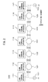
- FIG. 2 illustrates a configuration example of a submarine cable system to which one example of the power feeding system has been applied.
- the submarine cable system 100 includes land terminal apparatuses 111 to 117, undersea branching devices 121 to 125, and power feeding devices 131 and 132.
- the dashed line indicates a communication circuit
- the dashed-dotted line indicates a power feeding path.
- Each of the undersea branching devices 121 to 125 is one example of the power feeding path switching device.
- the following describes exemplification of the power feeding system that supplies electric power to repeaters provided between the land terminal apparatuses in the submarine cable system. However, this exemplification is not described with the intention that application of the power feeding system described in the present specification is limited only to an undersea cable system.
- the power feeding system described in the present specification is applicable to power feeding in systems used for various purposes.
- a segment between the land terminal apparatus 111 and the undersea branching device 121, a segment between the undersea branching devices 121 and 122, and a segment between the undersea branching devices 122 and 123 are repeating segments each of which a repeater is provided therebetween.
- a segment between the undersea branching devices 123 and 124, a segment between the undersea branching devices 124 and 125, and a segment between the undersea branching device 125 and the land terminal apparatus 117 are repeating segments as well.
- the undersea branching devices 121 to 125 branches the main communication line, the main communication line connecting the land terminal apparatus 111 and the land terminal apparatus 117 to each other.
- the land terminal apparatuses 112 to 116 are branch stations connected to branch communication lines that are branched from the main communication line by the undersea branching devices 121 to 125, respectively.
- the communication lines may be an optical fiber, for example, and each of the undersea branching devices 121 to 125 may include an optical add-drop multiplexer (OADM device) that separates or multiplexes an optical signal traveling in the communication line.
- OADM device optical add-drop multiplexer
- the communication lines may be transmission media other than an optical fiber.
- the branch communication lines that respectively connect the undersea branching devices 121 to 125 with the land terminal apparatuses 112 to 116 may be non- repeating segments that do not include a repeater therebetween. In a modified example, a part of or all of these branch communication lines may be repeating segments.
- the power feeding line is provided between the land terminal apparatuses 111 and 117.
- the power feeding devices 131 and 132 causes a power supply current to flow in the power feeding line by the both ends of the power feeding line. It is assumed that in a normal operating state, a direction of a power supply current is a direction toward the land terminal apparatus 117 from the land terminal apparatus 111.
- the electric power is supplied through the power feeding path to the repeaters 941 to 944 that are provided in the main communication line between the land terminal apparatuses 111 and 117.
- FIG. 3 illustrates a configuration of a first example of the undersea branching device 121.
- the undersea branching devices 122 to 125 may have the same configuration as the undersea branching device 121.
- the functional configuration of FIG. 3 mainly illustrates the configuration related to a function of the undersea branching device 121 described in the present specification.
- the undersea branching device 121 may include constituting elements other than the constituting elements illustrated in the drawing. This description also applies to a configuration illustrated in FIG. 5 , FIG. 11 , and FIG. 15 .
- the undersea branching device 121 includes a relay RL1 and a power feeding circuit 201.
- the power feeding circuit 201 receives electric power from a power feeding path, and supplies the electric power to each circuit in the undersea branching device 121.
- the relay RL1 is an electric relay connected in series between the power feeding path on the side of the land terminal apparatus 111 and the power feeding circuit 201.
- the reference symbol rl1 designates contact points of the relay RL1. When a coil of the relay RL1 is not excited, an NC terminal and a COM terminal are connected to each other. When a coil of the relay RL1 is excited, an NO terminal and the COM terminal are connected to each other.
- the COM terminal of the relay RL1 is grounded under the sea.
- the NC terminal is connected to the power feeding path via the power feeding circuit 201.
- the relay RL1 is an electric relay that has a directional characteristic. In other words, when an electric current flows in either one of the direction in the power feeding path connected in series to the relay RL1, the coil is excited, and when an electric current flows in the opposite direction, the coil is not excited. In the present embodiment, when a power supply current flows from the reference mark A to the reference mark C in the drawing, the coil is excited.
- the reference mark A is a power feeding path between the undersea branching device 121 and the land terminal apparatus 111, for example.
- the reference mark C is a power feeding path between the undersea branching devices 121 and 122.
- the coil is not excited.
- the power feeding devices 131 and 132 stop power feeding. As a result, a power supply current is stopped, so that the coil of the relay RL1 becomes unexcited. Accordingly, the NC terminal is connected to the COM terminal to connect the power feeding path to the ground via the contact points rl1.
- the power feeding devices 131 and 132 reverse the polarity to restart power feeding.
- the coil of the relay RL1 is not excited because of the directional characteristic, so that connection of the power feeding path to the ground via the contact points rl1 is maintained. Accordingly, a power supply current is allowed to flow in the segment between the undersea branching device 121 connected to the ground and the land terminal apparatus 111. Likewise, a power supply current flows in the segment between the undersea branching device 125 and the land terminal apparatus 117. As a result, in these segments, a power supply current is supplied again to the repeaters, and in a part of the segments, signal is allowed to be transmitted again.
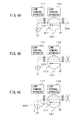
- FIG. 4A, FIG. 4B, and FIG. 4C illustrate one example of operation of the undersea branching device 121.
- the contact points rl11 in the drawings indicate a connection state between the NC terminal and the COM terminal.
- a power supply current 500 is made to flow in the direction from the land terminal apparatus 111 to the land terminal apparatus 117. Since the coil of the relay RL1 is excited, the power feeding path is not connected to the ground via the contact points rl1.
- the power feeding devices 131 and 132 reverse the polarity to restart power feeding. Accordingly, the coil of the relay RL1 is not excited, so that connection of the power feeding path to the ground is maintained. For this reason, a power supply current 501 is allowed to flow in the segment between the undersea branching device 121 connected to the ground and the land terminal apparatus 111.
- the undersea branching device makes it possible for the power feeding path to be connected to the ground. For this reason, it is possible to secure a power feeding route between the land terminal apparatus and the undersea ground. Further, even without power feeding from the branch station to the power feeding path for the branch transmission path, the power feeding path is able to be restored.
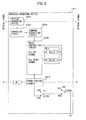
- FIG. 5 illustrates a configuration of a second example of the undersea branching device 121.
- the same reference symbols as the reference symbols used in FIG. 3 are attached to the same constituting elements as the constituting elements illustrated in FIG. 3 , and description about the same functions is omitted.
- the undersea branching device 121 includes an optical branching device 202, a converting circuit 203, a command extracting circuit 204, a relay controlling circuit 205, and a latch relay RLa.
- the optical branching device 202 branches an optical signal traveling in the communication line.
- the converting circuit 203 converts, into an electric signal, the optical signal branched by the optical branching device 202.
- the command extracting circuit 204 extracts, from the electric signal, a command signal for the undersea branching device 121.
- This command signal includes an RLa set signal for setting the latch relay RLa, and an RLa reset signal for resetting the latch relay RLa.
- the relay controlling circuit 205 When the relay controlling circuit 205 receives the RLa set signal from the command extracting circuit 204, the relay controlling circuit 205 outputs a pulse signal to a relay coil RLa-S for setting the latch relay RLa, to set the latch relay RLa.
- the relay controlling circuit 205 receives the RLa reset signal from the command extracting circuit 204, the relay controlling circuit 205 outputs a pulse signal to a relay coil RLa-R for resetting the latch relay RLa, to reset the latch relay RLa.
- the latch relay RLa controls opening and closing of connection between the power feeding path and the ground, this connection being made via the contact points rl1 of the relay RL1.
- the latch relay RLa opens the connection between the power feeding path and the ground regardless of whether the relay RLa is excited or not.
- the symbol rlA represents contact points of the latch relay RLa.
- the latch relay RLa is set so that the NO terminal is connected with the COM terminal.
- the latch relay RLa is reset so that the NC terminal is connected with the COM terminal.
- the NO terminal at the contact points rlA is connected to the COM terminal at the contact points rl1.
- the COM terminal at the contact points rlA is grounded under the sea.
- the latch relay RLa is reset. For this reason, even when the NC terminal and the COM terminal at the contact points rl1 are connected to each other before power feeding, the power feeding path is not connected to the ground since the NO terminal and the COM terminal at the contact points rlA are not connected to each other.
- the same description applies to the other undersea branching devices 122 to 125. Accordingly, at the time of starting power feeding, at each of the undersea branching devices 121 to 125, the power feeding path is not connected to the ground, so that the power feeding devices 131 and 132 are able to start both-end power feeding.
- the power supply current flows in the power feeding path to excite the coil of the relay RL1.
- the NO terminal and the COM terminal at the contact points rl1 are connected to each other, and disconnection is made between the NC terminal and the COM terminal at the contact points rl1.
- the relay controlling circuit 205 starts to operate.
- the land terminal apparatus 111 transmits, to the undersea branching devices 121 to 125, the RLa set signal by means of an optical signal, the latch relays RLa are set.
- the NO terminal and the COM terminal at the contact points rlA are connected to each other.
- the coil of the relay RL1 becomes unexcited.
- the NC terminal and the COM terminal at the contact points rl1 are connected to each other.
- the latch relay RLa is maintained to be set so that the NO terminal stays to be connected with the COM terminal at the contact points rlA. Accordingly, at all of the undersea branching devices 121 to 125, the power feeding path is connected to the ground.
- the power feeding devices 131 and 132 reverse the polarity to restart power feeding. Thereby, it is possible for a power supply current to flow in the segment between the undersea branching device 121 and the land terminal apparatus 111. Restarting power feeding between the undersea branching device 121 and the land terminal apparatus 111 causes the relay controlling circuit 205 of the undersea branching device 121 to operate.
- the land terminal apparatus 111 transmits the RLa reset signal to the undersea branching device 121, by means of an optical signal.
- the latch relay RLa of the undersea branching device 121 is reset so that disconnection is made between the NO terminal and the COM terminal at the contact points rlA. Thereby, the power feeding path becomes disconnected from the ground at the undersea branching device 121.
- the power feeding path is connected to the ground at the neighboring undersea branching device 122, so that a power supply current is supplied to the undersea branching device 122.
- resetting the latch relay RLa of the undersea branching device 121 causes a power supply current 501 to flow also in the segment between the undersea branching devices 121 and 122.
- the relay controlling circuit 205 of the undersea branching device 122 is made to operate, and the land terminal apparatus 111 then resets the latch relay RLa of the undersea branching device 122.
- the latch relays RLa of the respective undersea branching devices are reset.
- the latch relays RLa of the respective undersea branching devices are reset. In this manner, the power feeding path in the segments excluding the failure occurring segment is able to be restored.
- the land terminal apparatus 117 may transmit the command signal.
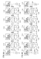
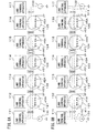
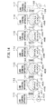
- FIG. 6A, FIG. 6B , and FIG. 7 illustrate one example of operation of the undersea branching devices 121 to 125 in FIG. 5 at the time of system start-up.
- the contact points rl11 to rl51 each indicate a connection state between the NC terminal and the COM terminal at the contact points rl1 of the corresponding one of the undersea branching devices 121 to 125.
- the contact points rl1A to rl5A each indicate a connection state between the NO terminal and the COM terminal at the contact points rlA of the corresponding one of the undersea branching devices 121 to 125.
- FIG. 8A, FIG. 8B , FIG. 9A, FIG. 9B , FIG. 10A, and FIG. 10B are the same description applies.
- FIG. 6A illustrates an initial state of the submarine cable system 100.
- the contact points rl11 to rl51 are closed before a power supply current flows in the power feeding path.
- the latch relays RLa of the undersea branching devices 121 to 125 are reset, and the contact points rl1A to rl5A are opened. Accordingly, the power feeding path is not connected to the ground at the undersea branching devices 121 to 125, and it is possible for the power feeding devices 131 and 132 supply to start both-end power feeding.
- the RLa set signal is transmitted from one of the land terminal apparatuses 111 to 117 to the undersea branching devices 121 to 125.
- the contact points rl1A to rl5A are closed to be the normal operation state illustrated in FIG. 7 .
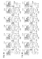
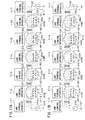
- FIG. 8A, FIG. 8B , FIG. 9A, FIG. 9B , FIG. 10A, and FIG. 10B illustrate one example of operation of the undersea branching devices 121 to 125 in FIG. 5 when a failure occurs. It is assumed that a cable open failure occurs between the undersea branching devices 123 and 124. This state is illustrated in FIG. 8A .
- the failure occurrence causes the power feeding devices 131 and 132 to stop power feeding. As a result, the contact points rl11 to rl51 are closed. Meanwhile, the contact points rl1A to rl5A are maintained to be closed. For this reason, at all of the undersea branching devices 121 to 125, the power feeding path is connected to the ground.
- the power feeding devices 131 and 132 reverse the polarity to restart power feeding. This state is illustrated in FIG. 8B . Since the power feeding path is connected to the ground at the undersea branching device 121, a power supply current 510 is allowed to flow in the segment between the undersea branching device 121 and the land terminal apparatus 111. Likewise, a power supply current 511 is allowed to flow in the segment between the undersea branching device 125 and the land terminal apparatus 117.
- Restarting power feeding causes the repeaters to operate in these segments so that an optical signal is communicated between the land terminal apparatuses 111 and 112, and between the land terminal apparatuses 116 and 117. Further, the relay controlling circuits 205 of the undersea branching devices 121 and 125 are made to operate.
- the land terminal apparatuses 111 and 117 determine whether or not rated currents flow in the respective undersea branching devices 121 and 125, and the relay controlling circuits 205 are thereby operating. For example, the land terminal apparatuses 111 and 117 may determine whether or not the rated currents are flowing in the undersea branching devices 121 and 125, in accordance with an electric potential difference between the ground and the power feeding line on the side of the power feeding device 131, and an electric potential difference between the ground and the power feeding line on the side of the power feeding device 132.
- the land terminal apparatuses 111 and 117 determine that the rated currents are flowing in the undersea branching devices 121 and 125.
- the electric potential differences are lower than the threshold, the land terminal apparatuses 111 and 117 determine that the rated currents are not flowing.
- the land terminal apparatuses 111 and 117 may determine whether or not the rated currents are flowing, on the basis of whether the undersea branching devices 121 and 125 or the relay controlling circuits 205 transmit predetermined response signals or not.
- the land terminal apparatus 111 transmits the RLa reset signal to the undersea branching device 121.
- the land terminal apparatus 117 transmits the RLa reset signal to the undersea branching device 125.
- the land terminal apparatuses 111 and 117 do not determine whether or not the rated current is flowing, and instead, may continue to successively transmit the RLa reset signal. The reason of this is that the RLa reset signal is only discarded when the relay controlling circuit 205 is not operating.
- Resetting the latch relays RLa of the undersea branching devices 121 and 125 causes the contact points rl1A and rl5A to be opened. This state is illustrated in FIG. 9A . Opening the contact points rl1A and rl5A causes the power feeding path to be disconnected from the ground at the undersea branching devices 121 and 125. Accordingly, as illustrated in FIG. 9B , the power supply currents 512 and 513 flow into the undersea branching devices 122 and 124, respectively.
- the power supply currents 512 and 513 cause the repeaters to operate, in the segment between the land terminal apparatus 111 and the undersea branching device 122, and in the segment between the land terminal apparatus 117 and the undersea branching device 124.
- an optical signal is communicated between the land terminal apparatuses 111 and 113, and between the land terminal apparatuses 115 and 117.
- the relay controlling circuits 205 of the undersea branching devices 122 and 124 are made to operate.
- the land terminal apparatus 111 determines whether or not the rated current is flowing in the undersea branching device 122.
- the land terminal apparatus 111 transmits the RLa reset signal to the undersea branching device 122.
- Resetting the latch relay RLa of the undersea branching device 122 causes the contact points rl2A to be opened. This state is illustrated in FIG. 10A .
- the contact points rl2A are opened, the power supply currents 514 and 513 flow into the undersea branching devices 123 and 124, respectively, as illustrated in FIG. 10B .
- the power supply current 514 causes the repeaters to operate, in the segment between the land terminal apparatus 111 and the undersea branching device 123. Thereby, between the land terminal apparatuses 111 and 114, an optical signal is communicated. As a result, communication becomes possible between the land terminal apparatuses 111 and 114, and between the land terminal apparatuses 115 and 117, except in the segment between the undersea branching devices 123 and 124 where the failure occurred.
- the latch relay RLa is provided and controls opening and closing of connection between the power feeding path and the ground, this connection being made via the contact points rl1 of the relay RL1. Thereby, it is possible to prevent the power feeding path from being grounded at the undersea branching device in the initial state of the submarine cable system 100.
- resetting the latch relay RLa enables to prevent the power feeding path from being connected with the ground. This prevents the power feeding path from being connected to the ground at the undersea branching devices other than the undersea branching devices at the both ends of a failure occurrence segment so that power feeding is allowed to be spread over the segments other than the failure occurrence segment.
- FIG. 11 illustrates a configuration of a third example of the undersea branching device 121.
- the same reference symbols as the reference symbols used in FIG. 5 are attached to the same constituting elements as the constituting elements illustrated in FIG. 5 , and description about the same functions is omitted.
- the undersea branching device 121 includes a latch relay RLb.
- the latch relay RLb controls opening and closing of connection between the power feeding path and the ground.
- the reference symbol rlB represents contact points of the latch relay RLb.
- the contact points rlB control opening and closing of connection between both ends of a series-connected circuit of the contact points rl1 of the relay RL1 and the contact points rlA of the latch relay RLa. For this reason, the NO terminal of the contact points rlB is connected to the NC terminal of the contact points rl1, and the COM terminal of the contact points rlB is connected to the COM terminal of the contact points rlA.
- Command signals extracted by the command extracting circuit 204 include an RLb set signal for setting the latch relay RLb, and an RLb reset signal for resetting the latch relay RLb.
- the relay controlling circuit 205 receives the RLb set signal from the command extracting circuit 204, the relay controlling circuit 205 outputs a pulse signal to a relay coil RLb-S for setting the latch relay RLb, to set the latch relay RLb.
- the relay controlling circuit 205 receives the RLb reset signal from the command extracting circuit 204, the relay controlling circuit 205 outputs a pulse signal to a relay coil RLb-R for resetting the latch relay RLb, to reset the latch relay RLb.
- the latch relay RLb As well as the latch relay RLa are reset. In addition, in a normal operation state, the latch relay RLb is reset.
- one of the land terminal apparatuses 111 to 117 transmits the RLb set signal to the undersea branching devices that are among undersea branching devices 121 to 125, and that are positioned at the both ends of a location where a cable shunt failure is occurring.
- the contact points R1B connect the power feeding path to the ground. Accordingly, the power feeding path is connected to the ground at the both ends of the failure occurrence location so that power feeding to the failure occurrence segment is stopped. For this reason, it is possible to perform failure restoring work safely.
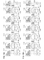
- FIG. 12A, FIG. 12B , FIG. 13A, FIG. 13B , and FIG. 14 illustrate one example of operation of the undersea branching devices 121 to 125 in FIG. 11 at the time of failure occurrence.
- the contact points rl11 to rl51 each indicate a connection state between the NC terminal and the COM terminal at the contact points rl1 of the corresponding one of the undersea branching devices 121 to 125.
- the contact points rl1A to rl5A each indicate a connection state between the NO terminal and the COM terminal at the contact points rlA of the corresponding one of the undersea branching devices 121 to 125.
- the contact points rl1B to rl5B each indicate a connection state between the NO terminal and the COM terminal at the contact points rlB of the corresponding one of the undersea branching devices 121 to 125.
- FIG. 12A illustrates a normal operation state before a failure occurs.
- a power supply current 500 is flowing in the power feeding path in the segment between the land terminal apparatus 111 and 117. It is assumed that a cable shunt failure occurs between the undersea branching devices 123 and 124. This state is illustrated in FIG. 12B . Even when the cable shunt failure occurs, a trouble does not occur in the signal transmission since the power feeding path is grounded in the seawater, therefore, power feeding is continued by one-end power feeding.
- One of the land terminal apparatuses 111 to 117 transmits the RLb set signal to the undersea branching devices 123 and 124 at the both ends of the failure occurrence location.
- This state is illustrated in FIG. 13A .
- the contact points rl3B and rl4B are closed so that power feeding path is connected to the ground at the undersea branching devices 123 and 124.
- a power supply current 510 flows in the segment from the land terminal apparatus 111 to the undersea branching device 123
- a power supply current 511 flows in the segment from the land terminal apparatus 117 to the undersea branching device 124. In the segment between the undersea branching devices 123 and 124, power feeding is stopped.
- the power supply current to the undersea branching device 124 from the side of the land terminal apparatus 111 is stopped.
- the relay RL1 of the undersea branching device 124 provided between the power feeding path on the side of the land terminal apparatus 111 and the power feeding circuit 201 is thereby made to be in an unexcited state. As a result, the contact points rl4 are closed.
- FIG. 13B illustrates a state when failure restoring work is completed.
- One of the land terminal apparatuses 111 to 117 transmits the RLb reset signal to the undersea branching devices 123 and 124 at the both ends of the failure occurrence location.
- the contact points rl3B and rl4B are opened.
- the closed contact points rl41 and rl4A cause a power supply current 512 to flow from the power feeding device 131 to the ground point of the undersea branching device 124, and cause a power supply current 513 to flow from the ground point of the undersea branching device 124 to the power feeding device 132.
- Flowing of the power supply current 512 from the side of the land terminal apparatus 111 to the undersea branching device 124 causes the relay RL1 of the undersea branching device 124 to be in an excited state.
- This state is illustrated in FIG. 14 .
- the relay RL1 thus becomes excited so that the contact points rl41 are opened.
- the power feeding path thus becomes unconnected to the ground at the undersea branching device 124 so that a power supply current 514 flows between the power feeding device 131 and the power feeding device 132.
- the normal operation state is recovered, where both-end power feeding is performed.
- the contact points rl41 of the relay RL1 are opened in a state where the power supply currents 512 and 513 are flowing though the contact points rl41. For this reason, for example, if values of the power supply currents 512 and 513 are larger than a rated opening-closing current value of the relay RL1, it is possible for the relay RL1 to be damaged.
- FIG. 15 illustrates a configuration of a fourth example of the undersea branching device 121.
- the same reference symbols as the reference symbols used in FIG. 11 are attached to the same constituting elements as the constituting elements illustrated in FIG. 11 , and description about the same functions is omitted.
- the undersea branching device 121 includes a latch relay RL2.
- the relay RL2 is an electric relay connected in series between the power feeding path on the side of the land terminal apparatus 117 and the power feeding circuit 201.
- the relay RL2 is provided between the contact points rlB of the latch relay RLb and the power feeding device 132 on the side of the land terminal apparatus 117.
- the relay RL1 is provided between the contact points rlB and the power feeding device 131 on the side of the land terminal apparatus 111.
- the relay RL2 is an electric relay that has a directional characteristic. In other words, when an electric current flows in the power feeding path in the direction of exciting the coil of the relay RL1, a coil of the relay RL2 is excited, and when an electric current flows in the direction opposite to the direction, the coil is not excited.
- the relay RL1 when a power supply current flows from the path A to the path C in the drawing, the coil is excited.
- the coil is not excited.
- the symbol rl2 represents contact points of the relay RL2.
- the NC terminal is connected with the COM terminal.
- the NO terminal is connected with the COM terminal.
- the NC terminal and the COM terminal of the contact points rl2 are connected in series to the NC terminal and the COM terminal of the contact points rl1 of the relay RL1, and are connected in series to the NO terminal and the COM terminal of the latch relay RLa.
- the NC terminal of the relay RL2 is connected to the COM terminal of the relay RL1, and the COM terminal of the relay RL2 is connected to the NO terminal of the latch relay RLa.
- the latch relay RLb is set. Thereby, a power supply current does not flow in the coil of the relay that is either the relay RL1 or RL2 and that is connected to the power feeding path positioned on the side of the failure occurrence segment. Accordingly, this coil becomes unexcited. On the other hand, a power supply current flows in the coil of the relay connected to the power feeding path on the side opposite to the failure occurrence segment since this electric current flows between the power feeding device and the ground that are connected by the contact points rlB of the latch relay RLb. Accordingly, this coil becomes excited.
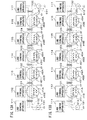
- FIG. 16A, FIG. 16B , FIG. 17A, and FIG. 17B illustrate one example of operation of the undersea branching devices 121 to 125 in FIG. 15 when a failure occurs.
- the contact points rl112 to rl512 respectively indicate opening-closing states of series connection of the contact points rl1 and rl2 in the undersea branching devices 121 to 125.
- the contact points rl1A to rl5A respectively indicate connection states between the NO terminal and the COM terminal of the contact points rlA of the undersea branching devices 121 to 125.
- the contact points rl1B to rl5B respectively indicate connection states between the NO terminal and the COM terminal of the contact points rlB of the undersea branching devices 121 to 125.
- FIG. 16A illustrates a normal operation state before a failure occurs.
- a power supply current 500 is flowing in the power feeding path in the segment between the land terminal apparatuses 111 and 117. It is assumed that a cable shunt failure occurs between the undersea branching devices 123 and 124. This state is illustrated in FIG. 16B .
- One of the land terminal apparatuses 111 to 117 transmits the RLb set signal to the undersea branching devices 123 and 124 at the both ends of the failure occurrence location.
- This state is illustrated in FIG. 17A .
- the contact points rl3B and rl4B are closed so that the power feeding path is connected to the ground at the undersea branching devices 123 and 124.
- a power supply current 510 flows in the segment from the land terminal apparatus 111 to the undersea branching device 123
- a power supply current 511 flows in the segment from the land terminal apparatus 117 to the undersea branching device 124. Power feeding is stopped in the segment between the undersea branching devices 123 and 124.
- the relay RL1 of the undersea branching device 124 becomes unexcited.
- the relay RL2 becomes excited since the power supply current 511 from the side of the land terminal apparatus 117 flows. For this reason, the contact points rl412 are maintained to be open. As a result, a power supply current does not flow through the contact points rl412.
- FIG. 17B illustrates a state at the time of completion of failure restoring work.
- One of the land terminal apparatuses 111 to 117 transmits the RLb reset signal to the undersea branching devices 123 and 124 at the both ends of the failure occurrence location.
- the contact points rl3B and rl4B are opened.
- a power supply current 512 flows between the power feeding device 131 and the power feeding device 132. Thereby, the normal operation state is recovered, where both-end power feeding is performed.
- the contact points of the relay RL1 or RL2 are prevented from being opened in a state where an electric current is flowing through this relay. Accordingly, it is possible to reduce a possibility of having damage at the time of opening the contact points through which an electric current is flowing.
Landscapes
- Engineering & Computer Science (AREA)
- Computer Networks & Wireless Communication (AREA)
- Signal Processing (AREA)
- Physics & Mathematics (AREA)
- Electromagnetism (AREA)
- Cable Transmission Systems, Equalization Of Radio And Reduction Of Echo (AREA)
- Relay Circuits (AREA)
Applications Claiming Priority (1)
| Application Number | Priority Date | Filing Date | Title |
|---|---|---|---|
| JP2012240848A JP6044274B2 (ja) | 2012-10-31 | 2012-10-31 | 給電路切替装置及び給電システム |
Publications (2)
| Publication Number | Publication Date |
|---|---|
| EP2728765A2 true EP2728765A2 (de) | 2014-05-07 |
| EP2728765A3 EP2728765A3 (de) | 2018-01-03 |
Family
ID=49110983
Family Applications (1)
| Application Number | Title | Priority Date | Filing Date |
|---|---|---|---|
| EP13181329.7A Withdrawn EP2728765A3 (de) | 2012-10-31 | 2013-08-22 | Stromversorgungspfadschaltvorrichtung und Stromversorgungssystem |
Country Status (3)
| Country | Link |
|---|---|
| US (1) | US20140117775A1 (de) |
| EP (1) | EP2728765A3 (de) |
| JP (1) | JP6044274B2 (de) |
Families Citing this family (2)
| Publication number | Priority date | Publication date | Assignee | Title |
|---|---|---|---|---|
| US10110321B2 (en) * | 2017-03-16 | 2018-10-23 | Tyco Electronics Subsea Communications Llc | Techniques for providing adaptive power distribution using a multi-node network of power feed branching units (PFBUs) and an undersea optical communication system using same |
| CN112385148B (zh) * | 2018-07-24 | 2022-06-03 | 日本电气株式会社 | 通信系统、用于通信系统的监测设备和监测方法 |
Citations (2)
| Publication number | Priority date | Publication date | Assignee | Title |
|---|---|---|---|---|
| JPH01220531A (ja) | 1988-02-29 | 1989-09-04 | Nippon Telegr & Teleph Corp <Ntt> | 海底ケーブル伝送路の給電分岐切替方法および切替装置 |
| JPH0436339U (de) | 1990-07-20 | 1992-03-26 |
Family Cites Families (9)
| Publication number | Priority date | Publication date | Assignee | Title |
|---|---|---|---|---|
| JPS5036938A (de) * | 1973-08-09 | 1975-04-07 | ||
| JPS5799042A (en) * | 1980-12-11 | 1982-06-19 | Nec Corp | Submarine relay system |
| JPH0815370B2 (ja) * | 1987-05-27 | 1996-02-14 | 日本電信電話株式会社 | 海底中継伝送路の給電切替方式 |
| JP2805197B2 (ja) * | 1988-05-16 | 1998-09-30 | 日本電信電話株式会社 | 海底中継伝送路の給電切替方式 |
| JPH04256225A (ja) * | 1991-02-07 | 1992-09-10 | Fujitsu Ltd | 海底ケーブル通信システムの給電方法および給電路切替え回路 |
| JPH04304716A (ja) * | 1991-04-02 | 1992-10-28 | Nec Corp | 海底ケーブルシステム給電方式 |
| JPH05327561A (ja) * | 1992-05-20 | 1993-12-10 | Fujitsu Ltd | 給電路切替回路 |
| JP3387614B2 (ja) * | 1994-03-17 | 2003-03-17 | 富士通株式会社 | 海中分岐装置の給電切替え回路 |
| US6211632B1 (en) * | 1999-09-08 | 2001-04-03 | Rhine Electronic Co., Ltd. | Direction control device for a ceiling fan |
-
2012
- 2012-10-31 JP JP2012240848A patent/JP6044274B2/ja not_active Expired - Fee Related
-
2013
- 2013-08-14 US US13/966,939 patent/US20140117775A1/en not_active Abandoned
- 2013-08-22 EP EP13181329.7A patent/EP2728765A3/de not_active Withdrawn
Patent Citations (2)
| Publication number | Priority date | Publication date | Assignee | Title |
|---|---|---|---|---|
| JPH01220531A (ja) | 1988-02-29 | 1989-09-04 | Nippon Telegr & Teleph Corp <Ntt> | 海底ケーブル伝送路の給電分岐切替方法および切替装置 |
| JPH0436339U (de) | 1990-07-20 | 1992-03-26 |
Also Published As
| Publication number | Publication date |
|---|---|
| US20140117775A1 (en) | 2014-05-01 |
| JP6044274B2 (ja) | 2016-12-14 |
| EP2728765A3 (de) | 2018-01-03 |
| JP2014093539A (ja) | 2014-05-19 |
Similar Documents
| Publication | Publication Date | Title |
|---|---|---|
| JP5682847B2 (ja) | 給電路切替装置、光海底分岐装置、海底ケーブルシステムおよび給電路切替方法 | |
| US10348440B2 (en) | Power supply path-switching device, power supply path-switching system, and power supply path-switching method | |
| CN108702177B (zh) | 接地电路和接地方法 | |
| EP3384613B1 (de) | Uferanlegevorrichtung für optisches unterseekabel | |
| KR101758601B1 (ko) | 수중 통신 데이터를 제공하기 위한 시스템 및 방법 | |
| JPWO2016147610A1 (ja) | 拡張分岐装置及び拡張分岐装置の制御方法 | |
| EP3691134B1 (de) | Unterwasserverzweigungseinheit und unterwasserverzweigungsverfahren | |
| EP2728765A2 (de) | Stromversorgungspfadschaltvorrichtung und Stromversorgungssystem | |
| US11994728B2 (en) | Junction device, and undersea cable system | |
| JPH05327561A (ja) | 給電路切替回路 | |
| JP6962441B2 (ja) | 海底ケーブルシステム、分岐装置及びその状態応答方法 | |
| EP1294113B1 (de) | Verzweigungseinheit für ein optisches Übertragungssystem | |
| CN115917992A (zh) | 海底光缆系统 |
Legal Events
| Date | Code | Title | Description |
|---|---|---|---|
| PUAI | Public reference made under article 153(3) epc to a published international application that has entered the european phase |
Free format text: ORIGINAL CODE: 0009012 |
|
| 17P | Request for examination filed |
Effective date: 20130822 |
|
| AK | Designated contracting states |
Kind code of ref document: A2 Designated state(s): AL AT BE BG CH CY CZ DE DK EE ES FI FR GB GR HR HU IE IS IT LI LT LU LV MC MK MT NL NO PL PT RO RS SE SI SK SM TR |
|
| AX | Request for extension of the european patent |
Extension state: BA ME |
|
| PUAL | Search report despatched |
Free format text: ORIGINAL CODE: 0009013 |
|
| AK | Designated contracting states |
Kind code of ref document: A3 Designated state(s): AL AT BE BG CH CY CZ DE DK EE ES FI FR GB GR HR HU IE IS IT LI LT LU LV MC MK MT NL NO PL PT RO RS SE SI SK SM TR |
|
| AX | Request for extension of the european patent |
Extension state: BA ME |
|
| RIC1 | Information provided on ipc code assigned before grant |
Ipc: H04B 3/44 20060101AFI20171124BHEP |
|
| STAA | Information on the status of an ep patent application or granted ep patent |
Free format text: STATUS: THE APPLICATION IS DEEMED TO BE WITHDRAWN |
|
| 18D | Application deemed to be withdrawn |
Effective date: 20180704 |