EP2733391A1 - Dispositif de levier de changement de vitesses comprenant un levier et un pommeau - Google Patents
Dispositif de levier de changement de vitesses comprenant un levier et un pommeau Download PDFInfo
- Publication number
- EP2733391A1 EP2733391A1 EP20130191890 EP13191890A EP2733391A1 EP 2733391 A1 EP2733391 A1 EP 2733391A1 EP 20130191890 EP20130191890 EP 20130191890 EP 13191890 A EP13191890 A EP 13191890A EP 2733391 A1 EP2733391 A1 EP 2733391A1
- Authority
- EP
- European Patent Office
- Prior art keywords
- button
- shift
- tubular portion
- cores
- core
- Prior art date
- Legal status (The legal status is an assumption and is not a legal conclusion. Google has not performed a legal analysis and makes no representation as to the accuracy of the status listed.)
- Granted
Links
- 230000008878 coupling Effects 0.000 description 19
- 238000010168 coupling process Methods 0.000 description 19
- 238000005859 coupling reaction Methods 0.000 description 19
- 238000000034 method Methods 0.000 description 13
- 229920003002 synthetic resin Polymers 0.000 description 12
- 239000000057 synthetic resin Substances 0.000 description 12
- 238000003780 insertion Methods 0.000 description 11
- 230000037431 insertion Effects 0.000 description 11
- 238000000465 moulding Methods 0.000 description 11
- 230000008569 process Effects 0.000 description 11
- 238000009434 installation Methods 0.000 description 9
- 239000002184 metal Substances 0.000 description 8
- 230000005540 biological transmission Effects 0.000 description 5
- 230000000717 retained effect Effects 0.000 description 5
- 230000004048 modification Effects 0.000 description 4
- 238000012986 modification Methods 0.000 description 4
- 238000011900 installation process Methods 0.000 description 3
- 238000005452 bending Methods 0.000 description 1
- 239000000463 material Substances 0.000 description 1
- 230000000149 penetrating effect Effects 0.000 description 1
Images







Classifications
-
- F—MECHANICAL ENGINEERING; LIGHTING; HEATING; WEAPONS; BLASTING
- F16—ENGINEERING ELEMENTS AND UNITS; GENERAL MEASURES FOR PRODUCING AND MAINTAINING EFFECTIVE FUNCTIONING OF MACHINES OR INSTALLATIONS; THERMAL INSULATION IN GENERAL
- F16H—GEARING
- F16H59/00—Control inputs to control units of change-speed- or reversing-gearings for conveying rotary motion
- F16H59/02—Selector apparatus
- F16H59/08—Range selector apparatus
- F16H59/10—Range selector apparatus comprising levers
-
- F—MECHANICAL ENGINEERING; LIGHTING; HEATING; WEAPONS; BLASTING
- F16—ENGINEERING ELEMENTS AND UNITS; GENERAL MEASURES FOR PRODUCING AND MAINTAINING EFFECTIVE FUNCTIONING OF MACHINES OR INSTALLATIONS; THERMAL INSULATION IN GENERAL
- F16H—GEARING
- F16H59/00—Control inputs to control units of change-speed- or reversing-gearings for conveying rotary motion
- F16H59/02—Selector apparatus
- F16H59/0278—Constructional features of the selector lever, e.g. grip parts, mounting or manufacturing
-
- F—MECHANICAL ENGINEERING; LIGHTING; HEATING; WEAPONS; BLASTING
- F16—ENGINEERING ELEMENTS AND UNITS; GENERAL MEASURES FOR PRODUCING AND MAINTAINING EFFECTIVE FUNCTIONING OF MACHINES OR INSTALLATIONS; THERMAL INSULATION IN GENERAL
- F16H—GEARING
- F16H61/00—Control functions within control units of change-speed- or reversing-gearings for conveying rotary motion ; Control of exclusively fluid gearing, friction gearing, gearings with endless flexible members or other particular types of gearing
- F16H61/18—Preventing unintentional or unsafe shift, e.g. preventing manual shift from highest gear to reverse gear
-
- F—MECHANICAL ENGINEERING; LIGHTING; HEATING; WEAPONS; BLASTING
- F16—ENGINEERING ELEMENTS AND UNITS; GENERAL MEASURES FOR PRODUCING AND MAINTAINING EFFECTIVE FUNCTIONING OF MACHINES OR INSTALLATIONS; THERMAL INSULATION IN GENERAL
- F16H—GEARING
- F16H61/00—Control functions within control units of change-speed- or reversing-gearings for conveying rotary motion ; Control of exclusively fluid gearing, friction gearing, gearings with endless flexible members or other particular types of gearing
- F16H61/22—Locking of the control input devices
-
- F—MECHANICAL ENGINEERING; LIGHTING; HEATING; WEAPONS; BLASTING
- F16—ENGINEERING ELEMENTS AND UNITS; GENERAL MEASURES FOR PRODUCING AND MAINTAINING EFFECTIVE FUNCTIONING OF MACHINES OR INSTALLATIONS; THERMAL INSULATION IN GENERAL
- F16H—GEARING
- F16H59/00—Control inputs to control units of change-speed- or reversing-gearings for conveying rotary motion
- F16H59/02—Selector apparatus
- F16H59/0278—Constructional features of the selector lever, e.g. grip parts, mounting or manufacturing
- F16H2059/0282—Lever handles with lock mechanisms, e.g. for allowing selection of reverse gear or releasing lever from park position
-
- Y—GENERAL TAGGING OF NEW TECHNOLOGICAL DEVELOPMENTS; GENERAL TAGGING OF CROSS-SECTIONAL TECHNOLOGIES SPANNING OVER SEVERAL SECTIONS OF THE IPC; TECHNICAL SUBJECTS COVERED BY FORMER USPC CROSS-REFERENCE ART COLLECTIONS [XRACs] AND DIGESTS
- Y10—TECHNICAL SUBJECTS COVERED BY FORMER USPC
- Y10T—TECHNICAL SUBJECTS COVERED BY FORMER US CLASSIFICATION
- Y10T74/00—Machine element or mechanism
- Y10T74/20—Control lever and linkage systems
- Y10T74/20012—Multiple controlled elements
- Y10T74/20018—Transmission control
- Y10T74/20085—Restriction of shift, gear selection, or gear engagement
- Y10T74/20098—Separate actuator to disengage restrictor
Definitions
- the present invention relates to a button structure of a shift knob.
- an automobile transmission shift lever device has been known as disclosed, for example, in JP-U 05-001552A .
- this type of shift lever device is configured such that, when a button 21 of a shift knob 20 is manually pushed (see the arrowed line a in FIG. 11 ) and set to a push mode (pushing operation), a rod 22 is moved to a shift-lock release position (see the arrowed line b in FIG. 11 ). Then, when the button 21 of the shift knob 20 is manually released from the push mode (push-mode releasing operation), the rod is moved to a shift-lock position.
- a slide cam 23 having an inclined contact surface is pressed downwardly, and thereby the rod 22 is moved downwardly to the shift-lock release position.
- This button structure is configured such that the slide cam 23 is slidingly moved with respect to the button 21, which causes an increase in transmission loss of load from the pushing operation of the button to the slide cam 23.
- the pushing operation of the button is liable to become heavy and awkward.
- a button structure of a shift knob for use with a shift lever in which a rod is provided in an upwardly and downwardly movable manner is characterized in that the shift knob comprises: a button capable of being manually pushed while being supported in a swingable manner, to allow the rod to be moved downwardly from a lock position to a lock release position; a pinion gear provided in coaxial relation to a pivot shaft of the button; and a rack meshed with the pinion gear, wherein the button structure is configured to move the rod to a shift-lock release position, interlockingly with a downward movement of the rack caused by a swinging movement of the pinion gear in a forward direction, according to a pushing operation of the button, and to move the rod to a shift-lock position, interlockingly with an upward movement of the rack caused by a swinging movement of the pinion gear in a reverse direction, according to a push-mode releasing operation of the button.
- a shift knob 1 primarily, a button structure thereof, in a shift knob installation structure according to one embodiment of the present invention.
- FIG. 1 is a perspective view of the shift knob 1.
- FIG. 2 is an exploded perspective view of the shift knob 1.
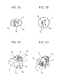
- FIGS. 3A and 3B are perspective views of an ornament 8.
- FIGS. 3C and 3D are perspective views of a button base 6.
- FIG. 4A is a sectional view of the shift knob 1 in a state when a button 2 thereof is in a push-mode release position.
- FIG. 4B is a sectional view of the shift knob 1 in a state when the button 2 is in a push-mode position.
- FIG. 5 is a front sectional view of the shift knob.
- a shift lever 3 is, for example, an automobile transmission shift lever.
- a shift lever device using the shift lever 3 is configured such that, according to when the button 2 of the shift knob 1 is manually pushed and set to a push mode (a pushing operation in a direction indicated by the arrowed line a in FIG. 4B ), a rod 4 held inside a shift shaft 3a of the shift lever 3 in an upwardly and downwardly movable manner is moved downwardly as indicated by the arrowed line b. Through this operation, the rod 4 is set to a shift-lock release position. Then, when the button 2 of the shift knob 1 is manually released from the push mode and moved in a direction as indicated by the arrowed line c in FIG. 4A (a push-mode releasing operation), the rod 4 is moved upwardly as indicated by the arrowed line d in FIG. A, and returned to its initial position. Through the above push release operation, the rod 4 is set to a shift-lock position.
- the shift knob 1 comprises: a button base 6; a core 7 comprised of a pair of left and right half-cores 7A, 7B made of a synthetic resin and the half-cores 7A, 7B being assembled (joined) together while clamping the button base 6 from opposed lateral directions, thereby installing the button base 6 in the core 7; and an ornament (decorative member) 8 made of a synthetic resin and attached to an upper side of the core 7 (i.e. the assembled half-cores 7A, 7B) to cover the upper side of the core 7.
- the shift knob 1 further comprises a cover ring 9, made of a synthetic resin, attached to lower tubular portion 7a of the core 7 to cover the lower tubular portion 7a.
- Each of the half-cores 7A, 7B has the lower semi-tubular portion 7a1, and a semi-bulging portion 7s1 connecting to an upper edge of the lower semi-tubular portion 7a and having a shape bulging outwardly with respect to the lower semi-tubular portion 7a1.
- the pair of the lower semi-tubular portion 7a1, 7a1 forms the lower tubular portion 7a.
- the pair of semi-bulging portion 7s1, 7s1 forms a bulging portion 7s.
- the button base 6 has two sidewalls 6a, 6b arranged in parallel relation to each other, and a connection wall 6g connecting the sidewalls 6a, 6b together.
- Each of the sidewalls 6a, 6b supports a respective one of opposite ends of a pivot shaft 11 penetrating through a pivot-shaft receiving hole 2a of the button 2.
- the pivot shaft 11 is provided with a coil spring 12 wound therearound to bias the button 2 in a push-mode releasing direction. It is to be understood that the button 2 may be biased in a pushing direction, instead of being biased in the push-mode releasing direction as in this embodiment.
- the sidewalls 6a, 6b of the button base 6 may be integrally molded with a pair of pivot-protrusion receiving holes, respectively.
- the button 2 may have a pair of pivot protrusions each formed on a respective one of opposite side surfaces thereof in such a manner as to be fittable into a respective one of the pivot-protrusion receiving holes of the button base 6, through an integral molding process. Then, each of the pivot protrusions of the button 2 is fitted into a respective one of the pivot-protrusion receiving holes of the button base 6, while bending each of the sidewalls 6a, 6b of the button base 6 outwardly, so that the button 2 is rotatably supported by the button base 6. This makes it possible to omit the pivot shaft 11.
- the button base 6 may be integrally molded with an elastic piece for biasing the button 2 in the push-mode releasing direction or in the pushing direction. This makes it possible to omit the coil spring 12.
- the button 2 has a multi-tooth (in this embodiment, 5-tooth) pinion gear 13 formed on an end thereof opposite to a side to be manually pushed, in coaxial relation to the pivot shaft 11, through an integral molding process.
- the pinion gear 13 may be formed as a separate component from the button 2. That is, in the case where a button 2 is designed while attaching importance to aesthetics, a pinion gear 13 formed separately from the button 2 while attaching importance to strength may be fixed to the button 2.
- the button base 6 is provided with a guide groove 6e extending in an up-down direction.
- the guide groove 6e is configured to allow a convex portion 14a of a rack 14 to be fitted thereinto.
- the rack 14 meshed with the pinion gear 13 is supported by the guide groove 6e in an upwardly and downwardly movable manner. That is, the rack 14 is supported by the button base 6.
- a lower end of the rack 14 is in contact with an upper end of the rod 4.
- the button 2, the pivot shaft 11, the coil spring 12 and the rack 14 are preliminarily assembled to the button base 6.
- the core 7 is provided with a cutout 7t for allowing the button 2 to penetrate therethrough. Although the button 2 is installed in the core 7, a part of the button 2 is exposed to the outside through the cutout 7t.
- Each of the pair of generally semi-cylindrical shaped half-cores 7A, 7B has an upper protrusion 7b and a lower protrusion 7c formed on an inner surface thereof (see FIG. 5 ).
- the upper protrusion 7b and the lower protrusion 7c are fitted, respectively, into an upper hole 6c and a lower hole 6d of a corresponding one of the sidewalls 6a, 6b of the button base 6, from a lateral direction.
- each of a pair of top half-walls 7d, 7e of the half-cores 7A, 7B is formed with two insertion holes 7f, 7g.
- each of two sets of the upper protrusion 7b and the lower protrusion 7c is fitted into a corresponding one of two sets of the upper hole 6c and the lower hole 6d of the button base 6. Therefore, when the button base 6 is clamped from opposed lateral directions by the pair of half-cores 7A, 7B, the button base 6 is installed in and held by the core 7 while being fixed at a given position within the core 7.
- a part of the top half-wall 7e of the right half-core 7B gets into under a part of the top half-wall 7d of the left half-core 7A, in such a manner as to allow each of the insertion holes 7f, 7g of the top half-wall 7d to be aligned with a respective one of the insertion holes 7f, 7g of the top half-wall 7e in an up-down direction.
- each of the half-cores 7A, 7B is formed with the lower semi-tubular portion 7a1 shaped in a semi-cylindrical shape.
- the lower semi-tubular portions 7a1,7a1 of the half-cores 7A, 7B are assembled into a lower tubular portion 7a having a circular tubular shape.
- a plurality of sets of upper and lower, two, locking recesses (locking holes) 7h, 7i are formed in the lower tubular portion 7a, at approximately even angular intervals (in this embodiment, at intervals of 180 degrees) in a circumferential direction, and in a symmetrical manner with respect to an axis of the lower tubular portion 7a.
- the core is not necessarily formed in the pair of generally semi-cylindrical shaped half-cores 7A, 7B to be joined together from opposed lateral directions, but may be formed in an integrated cylindrical core.
- the ornament 8 is formed in an upwardly-convexed generally hemispherical (arc face-like) shape, and two insertion shafts 8a, 8b are formed on a lower surface thereof.
- Each of the insertion shafts 8a, 8b is configured, when the ornament 8 is put on the top half-walls 7d, 7e of the core 7 in a state that the half-cores 7A, 7B are joined from opposed lateral directions, to be aligned with a corresponding one of the aligned insertion holes 7f, 7g, in an up-down direction.
- the insertion shafts 8a, 8b are inserted, respectively, into the aligned insertion holes 7f, 7g, so that the top half-walls 7d, 7e of the pair of half-cores 7A, 7B are retained in an inseparable manner.
- the ornament 8 also has two insertion pawls 8c formed on the lower surface thereof in such a manner as to be insertable, respectively, into two slits 7j, 7k of the core 7. Then, each of the insertion pawls 8c is locked by a respective one of a pair of protrusions 6f formed, respectively, on the sidewalls 6a, 6b of the button base 6, so that the ornament 8 is attached to the core 7 while covering over the upper side of the core 7. In this operation, a coupling between corresponding ones of the insertion pawls 8c and the protrusions 6f is achieved in a snap fit manner.
- the snap fit means one type of mechanical joining technique for use in coupling between metal or plastic members, and a technique of fittingly coupling two members together by means of an elastic force of a material, thereby achieving fixing therebetween.
- the cover ring 9 is formed in a generally cylindrical shape, and a pair of lockable protrusions 9a are formed on an inner surface thereof in such a manner as to be lockable, respectively, to the two upper locking recesses 7h of the lower semi-tubular portions 7a1 of the half-cores 7A, 7B assembled into a cylindrical shape.
- Each of the lockable protrusions 9a extends upwardly from a bottom wall of the cover ring 9, and has a pawl formed an upper end thereof to protrude in a lateral direction. A coupling of each of the lockable protrusion 9a to a corresponding one of the locking recess 7h is achieved in a snap fit manner.
- each of the lockable protrusions 9a is locked by a respective one of the locking recesses 7h. In this way, the cover ring 9 is attached to the core 7 while covering the lower tubular portion 7a of the core 7.
- the shift shaft 3a of the shift lever 3 is made of a metal, and a synthetic resin sleeve 15A is integrally formed on an outer periphery of an upper portion of the shift shaft 3a by an outsert molding process.
- the sleeve 15A is formed with a pair of lockable protrusions 15a lockable, respectively, to the two lower locking recesses 7i of the lower semi-tubular portions 7a1 of the half-cores 7A, 7B assembled into a cylindrical shape.
- Each of the lockable protrusions 15a extends downwardly, and has a pawl formed a lower end thereof to protrude in a lateral direction.
- a coupling of each of the lockable protrusions 15a to a corresponding one of the locking recesses 7i is achieved in a snap fit manner.
- each of the upper and lower locking recesses 7h, 7i, the lockable protrusion 9a of the cover ring 9 and the lockable protrusion 15a of the shift shaft 3a is not limited to the above configuration in which two elements are provided at intervals of 180 degrees.
- three elements may be provided at intervals of 120 degrees, or four or more elements may be provided at given intervals.
- the button is swingably moved, and thereby the pinion gear 13 is swingably moved (rotated) in a forward direction. Accordingly, the rack 14 interlocking with the movement of the pinion gear 13 is moved downwardly, and thus the rod 4 is moved downwardly to the shift-lock release position.
- a force during the pushing operation of the button 2 is transmitted to the rod 4 via the pinion gear 13 and the rack 14, so that it becomes possible to reduce a transmission loss of load from the pushing operation of the button 2.
- This allows the pushing operation of the button 2 to be performed lightly and smoothly. Therefore, operational burden on an operator or driver can be reduced.
- the button 2 when the button 2 is subjected to the push-mode releasing operation, the pinion 13 is swingably moved in a reverse direction. Thus, the rod 4 is moved upwardly from the shift-lock release position to the initial shift-lock position. In conjunction therewith, the rack 14 is moved upwardly. Thus, the button 2 is returned to the initial position.
- the button 2 with the pinion gear 13, the pivot shaft 11, the coil spring 12 and the rack 14 can be preliminarily installed in the button base 6 and adjusted, and this pre-installed unit can be simply installed in the core 7 of the shift knob 1, so that it becomes possible to enhance installation performance.
- the pair of half-cores 7A, 7B are assembled together while clamping the button base 6 from opposed lateral directions, to install the button base 6 inside the core 7, and then the ornament 8 is attached to the upper side of the core 7 from thereabove.
- a coupling during the attachment is achieved in a snap fit manner.
- the cover ring 9 is attached to the lower tubular portion 7a of the core 7 to cover the lower tubular portion 7a.
- a coupling during the attachment is also achieved in a snap fit manner.
- the lower tubular portion 7a of the core 7 is attached to the shift shaft 3a of the shift lever 3.
- a coupling during the attachment is achieved in a snap fit manner.
- an installation process for the shift knob 1 can be performed.
- the shift knob 1 can be installed in a one-touch manner by an installation operation to be performed from one direction (up-down direction), so that it becomes possible to enhance the installation performance.
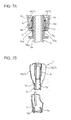
- FIGS. 6A to 6D and FIGS. 7A and 7B illustrate a push type structure according to one embodiment of the present invention.
- a fundamental structure of this embodiment has been described in connection with FIGS. 1 to 5 , and therefore functions and advantages thereof will be additionally described here.
- FIG. 6A is a sectional view of the core 7 and the cover ring 9 in a state before the cover ring 9 is fitted onto the lower tubular portion 7a of the core 7.
- FIG. 6B is a sectional view of the core 7 and the cover ring 9 in a state just after the cover ring 9 is fitted onto the lower tubular portion 7a of the core 7.
- FIG. 6C is a sectional view of the shift shaft 3a, the core 7 and the cover ring 9 in a state before the shift shaft 3a of the shift lever 3 is inserted into the lower tubular portion 7a of the core 7.
- FIG. 6A is a sectional view of the core 7 and the cover ring 9 in a state before the cover ring 9 is fitted onto the lower tubular portion 7a of the core 7.
- FIG. 6B is a sectional view of the core 7 and the cover ring 9 in a state just after the cover ring 9 is fitted onto the lower tubular portion 7a of the core 7.
- FIG. 6C is a sectional view
- FIG. 6D is a sectional view of the shift shaft 3a, the core 7 and the cover ring 9 in a state just after the shift shaft 3a of the shift lever 3 is inserted into the lower tubular portion 7a of the core 7.
- FIG. 7A is a fragmentary enlarged view of the structure in FIG. 6D
- FIG. 7B is an exploded perspective sectional view of the shift knob 1 and the cover ring 9.
- the shift knob 1 comprises the core 7 installing therein the button 2, and the cover ring 9 for covering the lower tubular portion 7a of the core 7.
- the cover ring 9 is attached to the outer periphery of the lower tubular portion 7a of the core 7, the lockable protrusions 9a are locked, respectively, by the upper locking recesses 7h of the lower tubular portion 7a of the core 7, and thereby locked by the core 7.
- a coupling during this operation is achieved in a snap fit manner.
- the number of components can also be reduced, because it is possible to eliminate a need for a separate component, such as a pin, for attaching the shift knob 1 to the shift shaft 3a of the shift lever 3.
- the synthetic resin sleeve 15A is integrally formed on the outer periphery of the upper portion of the metal shift shaft 3a of the shift lever 3 by an outsert molding process.
- the lockable protrusions 15a can be provided on the shift shaft 3a.
- the shift shaft 3a of the shift lever 3 is integrally formed with a synthetic resin support portion 18 (see FIG. 2 ) by an outsert molding process.
- the support portion 18 also serves as a swingable portion when the shift lever 3 is manually moved in front-rear and right-left directions. Therefore, by utilizing a step of outsert-molding the support portion 18, the synthetic resin sleeve 15A may be integrally outsert-molded in a simultaneous manner. This makes it possible to reduce the number of components.
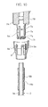
- FIGS. 8A to 10 illustrate a pull type structure according to one embodiment of the present invention.
- a fundamental structure of this embodiment has been described in connection with FIGS. 1 to 5 , and therefore a different feature and functions and advantages thereof will be additionally described here.
- FIG. 8A is a sectional view of a core 7 and a cover ring 9 in a state before the cover ring 9 is fitted onto a lower tubular portion 7a of the core 7.
- FIG. 8B is a sectional view of a shift shaft 3a of a shift lever 3, the core 7 and the cover ring 9 in a state just after the cover ring 9 is fitted onto the lower tubular portion 7a of the core 7, and temporarily retained by an intermediate locking recess.
- FIG. 8C is a sectional view of the shift shaft 3a, the core 7 and the cover ring 9 in a state just after the shift lever 3 is inserted into the lower tubular portion 7a of the core 7 and temporarily locked by a lower locking protrusion.
- FIG. 8D is a sectional view of the shift shaft 3a, the core 7 and the cover ring 9 in a state just after the cover ring 9 is snap-fitted into an upper locking recess.
- FIG. 9A is a fragmentary enlarged view of the structure in FIG. 8D
- FIG. 9B is a fragmentary enlarged view of an example of modification of the structure in FIG. 9A .
- FIG. 10 is an exploded perspective sectional view of the shift knob, the cover ring and the shift lever.
- the lower tubular portion 7a of the core 7 has a plurality of (in this embodiment, four) slits 7m formed at approximately even angular intervals (in the embodiment, at intervals of 90 degrees) in a circumferential direction, wherein each of the slits 7m extends from an lower end to a position close to an upper end of the lower tubular portion 7a. Further, a plurality of sets of upper, intermediate and lower, three, locking elements 7p, 7q, 7r are formed, respectively, in a plurality of regions of the lower tubular portion 7a divided by the slits 7m, in a symmetrical manner with respect to an axis of the lower tubular portion 7a.
- Each of the upper locking elements 7p and the intermediate locking elements 7q is a locking recess (or locking hole), and each of the lower locking elements 7r is an inwardly-oriented locking protrusion.
- Each of the regions of the lower tubular portion 7a divided by the slits 7m produces elasticity which allows a respective one of the lower locking elements 7r to be displaced inwardly.
- the cover ring 9 is formed a plurality of locking protrusions 9a each configured to be temporarily retained by a respective one of the intermediate locking recesses 7q when the cover ring 9 is fitted onto the outer periphery of the lower tubular portion 7a of the core 7 from therebelow.
- Each of the locking protrusions 9a extends upwardly from a lower portion of the cover ring 9, and has a pawl formed at an upper end thereof. A coupling of each of the lockable protrusions 9a to a corresponding one of the locking recesses 7q is achieved in a snap fit manner.
- the shift lever 3 is formed with a lockable recess 15b configured to be locked by the lower locking protrusions 7r when the shift shaft 3a is fitted into an inside of the lower tubular portion 7a of the core 7.
- a coupling of each of the locking protrusions 7r to the lockable recess 15b is achieved in a snap fit manner.
- a lockable hole may be formed in place of the lockable recess 15b.
- the shift shaft 3a of the shift lever 3 is made of a metal, and a synthetic resin sleeve 15B is integrally formed on an upper portion of the metal shift shaft 3a by an outsert molding process.
- the lockable recess 15b is formed in the sleeve 15B.
- the lockable recess 15b is configured to be locked by the lower locking protrusions 7r of the lower tubular portion 7a of the core 7 assembled into a cylindrical shape. A coupling of each of the locking protrusions 7r to the lockable recess 15b is achieved in a snap fit manner.
- each of the locking elements 7p, 7q, 7r of the core 7, the lockable protrusions 9a of the cover ring 9 and the lockable recess 15b of the shift lever 3 is not limited to the above configuration in which four elements are provided at intervals of 90 degrees.
- four elements may be formed at intervals of 180 degrees, or three elements may be may be formed at intervals of 120 degrees.
- five elements may be formed at intervals of 72 degrees, or six or more elements may be formed at given intervals.
- the cover ring 9 is moved upwardly. Through this operation, the lockable protrusions 9a of the cover ring 9 are rocked, respectively, by the upper locking recesses 7p. In this way, the cover ring 9 is locked by the lower tubular portion 7a.
- the cover ring 9 is fitted onto the lower tubular portion 7a of the core 7 from therebelow.
- the lockable protrusions 9a of the cover ring 9 are temporarily locked (temporarily retained), respectively, by the intermediate locking recesses 7q of the lower tubular portion 7a of the core 7.
- a coupling during this operation is achieved in a snap fit manner. That is, the cover ring 9 is retained in a state in which it can be further moved upwardly. Further, the shift shaft 3a of the shift lever 3 is inserted into the inside of the lower tubular portion 7a of the core 7 from therebelow.
- a shift knob installation process is based on a fitting operation to be performed from one direction (up-down direction), wherein the shift knob 1 can be attached to the shift shaft 3a of the shift lever 3 in a one-touch manner.
- the shift knob 1 can be attached to the shift shaft 3a of the shift lever 3 in a one-touch manner.
- the number of components can also be reduced, because it is possible to eliminate a need for a separate component, such as a pin, for attaching the shift knob 1 to the shift shaft 3a of the shift lever 3.
- the synthetic resin sleeve 15B is integrally formed on the outer periphery of the upper portion of the metal shift shaft 3a of the shift lever 3 by an outsert molding process. Then, the lockable recess 15b (or lockable hole) is formed in the sleeve 15B.
- the shift lever 3 is integrally formed with a synthetic resin support portion (see FIG. 2 ) 18 by an outsert molding process.
- the support portion 18 also serves as a swingable portion for allowing the shift lever 3 to be manually moved in front-rear and right-left directions. Therefore, by utilizing a step of outsert-molding the support portion 18, the synthetic resin sleeve 15A may be integrally outsert-molded in a simultaneous manner. This makes it possible to reduce the number of components.
- the synthetic resin sleeve 15B is integrally formed on the outer periphery of the upper portion of the metal shift shaft 3a of the shift lever 3 by an outsert molding process, and the lockable recess 15b is formed in the sleeve 15B.
- a lockable recess (or lockable hole) 3b may be directly formed in the metal shift shaft 3a of the shift lever 3.
- the shift shaft 3a of the shift lever 3 is inserted into the inside of the lower tubular portion 7a of the core 7 from therebelow, the lower locking protrusions 7r of the lower tubular portion 7a of the core 7 are locked to the lockable recess 3b of the shift lever 3.
- a coupling of each of the locking protrusions 7r to the lockable recess 3b is achieved in a snap fit manner.
- a locking element (recess or protrusion) and a lockable element (protrusion or recess) are formed in one, first, component and the other, second, component, respectively.
- a lockable element protrusion or recess
- a locking element may be formed in the first component and the second component, respectively.
- the rod (4) is moved to a shift-lock release position, interlockingly with a downward movement of the rack (14) meshed with the pinion (13), caused by a swinging movement of the pinion gear (13) in a forward direction, according to a pushing (swingingly moving) operation of the button (2).
- the pinion gear (13) and the rack (14) make it possible to reduce a transmission loss of load from the pushing operation of the button (2). This allows the pushing operation of the button (2) to be performed lightly and smoothly. Therefore, operational burden on an operator or driver can be reduced.
- the button (2) with the pinion gear (13), the pivot shaft, the coil spring (12) and the rack (14) can be preliminarily installed in the button base (6) and adjusted. Then, this pre-installed unit can be simply installed in the shift knob (1), so that it becomes possible to enhance installation performance.
- the pair of half-cores (7A, 7B) are assembled together while clamping the button base (6) from opposed lateral directions, to install the button base (6) inside the assembled half-cores (7A, 7B).
- the ornament (8) is attached to the upper side of the assembled half-cores (7A, 7B) in a nap fit manner.
- the cover ring (9) is attached to the lower tubular portion (7a) of the assembled half-cores (7A, 7B) in a snap fit manner.
- the lower tubular portion (7a) of the assembled half-cores (7A, 7B) is covered.
- the shift knob (1) can be installed to the shift lever (3).
- the shift knob (1) can be installed in a one-touch manner by an installation operation to be performed from one direction, so that it becomes possible to enhance the installation performance of the shift knob (1).
Landscapes
- Engineering & Computer Science (AREA)
- General Engineering & Computer Science (AREA)
- Mechanical Engineering (AREA)
- Arrangement Or Mounting Of Control Devices For Change-Speed Gearing (AREA)
- Transmission Devices (AREA)
- Mechanical Control Devices (AREA)
Applications Claiming Priority (1)
| Application Number | Priority Date | Filing Date | Title |
|---|---|---|---|
| JP2012252462A JP5973887B2 (ja) | 2012-11-16 | 2012-11-16 | シフトレバー用ノブのボタン構造 |
Publications (2)
| Publication Number | Publication Date |
|---|---|
| EP2733391A1 true EP2733391A1 (fr) | 2014-05-21 |
| EP2733391B1 EP2733391B1 (fr) | 2016-06-15 |
Family
ID=49546322
Family Applications (1)
| Application Number | Title | Priority Date | Filing Date |
|---|---|---|---|
| EP13191890.6A Not-in-force EP2733391B1 (fr) | 2012-11-16 | 2013-11-07 | Dispositif de levier de changement de vitesses comprenant un levier et un pommeau |
Country Status (4)
| Country | Link |
|---|---|
| US (1) | US9032829B2 (fr) |
| EP (1) | EP2733391B1 (fr) |
| JP (1) | JP5973887B2 (fr) |
| CN (1) | CN103821921B (fr) |
Cited By (1)
| Publication number | Priority date | Publication date | Assignee | Title |
|---|---|---|---|---|
| FR3063687A1 (fr) * | 2017-03-08 | 2018-09-14 | Peugeot Citroen Automobiles Sa | Dispositif de commande de boite de vitesse avec verouillage du pommeau sur la tige |
Families Citing this family (17)
| Publication number | Priority date | Publication date | Assignee | Title |
|---|---|---|---|---|
| KR101355617B1 (ko) * | 2012-10-26 | 2014-01-27 | 현대자동차주식회사 | 변속 레버 |
| JP6096480B2 (ja) * | 2012-11-16 | 2017-03-15 | デルタ工業株式会社 | シフトレバー用ノブの組み付け構造 |
| JP6137060B2 (ja) * | 2014-06-11 | 2017-05-31 | トヨタ自動車株式会社 | シフトノブ構造 |
| JP2016097900A (ja) * | 2014-11-25 | 2016-05-30 | 株式会社東海理化電機製作所 | シフト装置 |
| KR200479639Y1 (ko) | 2014-12-26 | 2016-02-19 | 에스엘 주식회사 | 자동 변속기용 변속레버 장치 |
| CN104747704A (zh) * | 2015-04-23 | 2015-07-01 | 安徽江淮汽车股份有限公司 | 换挡手柄及汽车 |
| JP6148712B2 (ja) * | 2015-11-05 | 2017-06-14 | 株式会社東海理化電機製作所 | シフト装置 |
| JP6557135B2 (ja) * | 2015-12-25 | 2019-08-07 | トヨタ自動車株式会社 | シフトレバー装置 |
| JP2017159676A (ja) * | 2016-03-07 | 2017-09-14 | 三菱自動車エンジニアリング株式会社 | シフトレバー |
| CN105605170B (zh) * | 2016-03-22 | 2018-11-13 | 林穗强 | 链节式齿条推拉杆 |
| JP6698043B2 (ja) * | 2017-03-14 | 2020-05-27 | 株式会社東海理化電機製作所 | シフト装置 |
| CN107176032B (zh) * | 2017-06-05 | 2019-07-16 | 汉喜龙汽车零部件(上海)有限公司 | 一种换挡手球 |
| CN109185441A (zh) * | 2018-10-31 | 2019-01-11 | 安徽江淮汽车集团股份有限公司 | 一种换档锁止机构及换档手柄 |
| CN109723673B (zh) * | 2019-03-02 | 2024-01-26 | 浙江优美莱智能科技有限公司 | 一种风扇枢转结构 |
| CN111765244B (zh) * | 2020-05-22 | 2022-02-15 | 北京理工大学 | 换挡装置 |
| CN112092615A (zh) * | 2020-09-07 | 2020-12-18 | 东风汽车集团有限公司 | 一种电子换挡手柄安装结构及装配方法 |
| CN115451116B (zh) * | 2022-09-01 | 2023-07-04 | 苏州爱和特科技有限公司 | 用于汽车变速器操纵机构的防错挡定位装置 |
Citations (6)
| Publication number | Priority date | Publication date | Assignee | Title |
|---|---|---|---|---|
| JPH051552U (ja) | 1991-06-27 | 1993-01-14 | 小島プレス工業株式会社 | 操作用ノブ |
| DE19513809C1 (de) * | 1995-04-12 | 1996-10-31 | Lemfoerder Metallwaren Ag | Schalthebel für ein Automatikgetriebe in einem Kraftfahrzeug |
| US5617760A (en) * | 1994-08-04 | 1997-04-08 | Bayerische Motoren Werke Aktiengesellschaft | Shift lever for a motor vehicle transmission |
| DE20003438U1 (de) * | 2000-02-24 | 2000-05-25 | Eissmann GmbH, 72574 Bad Urach | Schalthebel |
| US20030094066A1 (en) * | 1999-09-02 | 2003-05-22 | United Parts Fhs Automobil Systems Gmbh | Gear shift handle with push button mechanism for an automatic transmission in motor vehicles |
| DE202008010061U1 (de) * | 2008-07-26 | 2008-10-09 | Dura Automotive Systems Einbeck Gmbh | Handschalthebel mit Betätigungseinrichtung für eine Rückwärtsgangsperre |
Family Cites Families (19)
| Publication number | Priority date | Publication date | Assignee | Title |
|---|---|---|---|---|
| US1862098A (en) * | 1930-03-22 | 1932-06-07 | Ford Motor Co | Transmission |
| JPH0237045A (ja) * | 1988-07-26 | 1990-02-07 | Kubota Ltd | 歩行型移動農機のレバー操作構造 |
| JP2971205B2 (ja) | 1991-02-21 | 1999-11-02 | ヤマハ発動機株式会社 | 多弁式エンジンの吸気制御装置 |
| JP3662631B2 (ja) * | 1995-06-23 | 2005-06-22 | 株式会社東海理化電機製作所 | シフトレバーノブの取り付け構造 |
| US5957001A (en) * | 1997-05-01 | 1999-09-28 | Eaton Corporation | Transmission control lever with user interface |
| US6145401A (en) * | 1997-11-21 | 2000-11-14 | Caterpillar Inc. | Modular control handle |
| JP3664665B2 (ja) * | 2001-06-01 | 2005-06-29 | 株式会社カワサキプレシジョンマシナリ | ジョイスティック装置 |
| DE10158934A1 (de) * | 2001-12-03 | 2003-06-12 | Zf Lemfoerder Metallwaren Ag | Schaltknauf |
| DE10159642B4 (de) * | 2001-12-05 | 2008-01-10 | Bayerische Motoren Werke Ag | Schaltknauf |
| JP4101703B2 (ja) * | 2003-06-11 | 2008-06-18 | 富士機工株式会社 | シフトレバー装置 |
| US20060070482A1 (en) * | 2004-06-17 | 2006-04-06 | Deere & Company, A Delaware Corporation | Control lever with rotary wheel |
| US7546783B2 (en) * | 2005-11-17 | 2009-06-16 | Gm Global Technology Operations, Inc. | Motor vehicle shift handle attachment |
| US7779719B2 (en) * | 2006-11-22 | 2010-08-24 | Hsiu-Chih Wang | Combination of derailleur shifter and brake lever |
| JP4991825B2 (ja) * | 2009-10-29 | 2012-08-01 | タキゲン製造株式会社 | ハンドル装置 |
| KR101081052B1 (ko) * | 2009-12-01 | 2011-11-07 | 에스엘 주식회사 | 버튼식 변속노브를 구비한 변속레버 |
| JP5086390B2 (ja) * | 2010-05-10 | 2012-11-28 | 株式会社東海理化電機製作所 | シフトレバー |
| JP5475567B2 (ja) * | 2010-06-17 | 2014-04-16 | 株式会社東海理化電機製作所 | シフトレバー |
| JP5385866B2 (ja) * | 2010-06-30 | 2014-01-08 | 富士機工株式会社 | 車両用シフトレバー装置のシフトノブ装着構造 |
| JP2012071720A (ja) * | 2010-09-29 | 2012-04-12 | Fuji Kiko Co Ltd | 車両用シフトレバー装置のシフトノブ装着構造 |
-
2012
- 2012-11-16 JP JP2012252462A patent/JP5973887B2/ja not_active Expired - Fee Related
-
2013
- 2013-11-01 US US14/069,945 patent/US9032829B2/en not_active Expired - Fee Related
- 2013-11-07 EP EP13191890.6A patent/EP2733391B1/fr not_active Not-in-force
- 2013-11-08 CN CN201310552579.8A patent/CN103821921B/zh not_active Expired - Fee Related
Patent Citations (6)
| Publication number | Priority date | Publication date | Assignee | Title |
|---|---|---|---|---|
| JPH051552U (ja) | 1991-06-27 | 1993-01-14 | 小島プレス工業株式会社 | 操作用ノブ |
| US5617760A (en) * | 1994-08-04 | 1997-04-08 | Bayerische Motoren Werke Aktiengesellschaft | Shift lever for a motor vehicle transmission |
| DE19513809C1 (de) * | 1995-04-12 | 1996-10-31 | Lemfoerder Metallwaren Ag | Schalthebel für ein Automatikgetriebe in einem Kraftfahrzeug |
| US20030094066A1 (en) * | 1999-09-02 | 2003-05-22 | United Parts Fhs Automobil Systems Gmbh | Gear shift handle with push button mechanism for an automatic transmission in motor vehicles |
| DE20003438U1 (de) * | 2000-02-24 | 2000-05-25 | Eissmann GmbH, 72574 Bad Urach | Schalthebel |
| DE202008010061U1 (de) * | 2008-07-26 | 2008-10-09 | Dura Automotive Systems Einbeck Gmbh | Handschalthebel mit Betätigungseinrichtung für eine Rückwärtsgangsperre |
Cited By (1)
| Publication number | Priority date | Publication date | Assignee | Title |
|---|---|---|---|---|
| FR3063687A1 (fr) * | 2017-03-08 | 2018-09-14 | Peugeot Citroen Automobiles Sa | Dispositif de commande de boite de vitesse avec verouillage du pommeau sur la tige |
Also Published As
| Publication number | Publication date |
|---|---|
| CN103821921B (zh) | 2017-08-01 |
| EP2733391B1 (fr) | 2016-06-15 |
| CN103821921A (zh) | 2014-05-28 |
| US20140137684A1 (en) | 2014-05-22 |
| JP5973887B2 (ja) | 2016-08-23 |
| JP2014100946A (ja) | 2014-06-05 |
| US9032829B2 (en) | 2015-05-19 |
Similar Documents
| Publication | Publication Date | Title |
|---|---|---|
| US9032829B2 (en) | Button structure of shift knob | |
| EP2733392A2 (fr) | Structure d'installation de poignée de changement | |
| US20190101209A1 (en) | Shift Control Device Using Double Hinge | |
| EP2525120A2 (fr) | Sélecteur de vitesses de véhicule | |
| JP2009280052A (ja) | シフトレバー | |
| US10871222B2 (en) | Electronic shift control device | |
| EP2532929B1 (fr) | Ensemble de changement de vitesses modulaire pour véhicules à moteur | |
| JP2014004974A (ja) | シフトレバー装置 | |
| EP1953423A2 (fr) | Appareil de levier de vitesse pour transmission automatique | |
| US20060230858A1 (en) | Shift lever device | |
| JP4832317B2 (ja) | 複合操作型入力装置 | |
| CN105960555B (zh) | 用于变速器的换挡装置 | |
| KR20110012413A (ko) | 자동변속기용 노브의 원터치 결합구조 | |
| JP4990191B2 (ja) | シフトレバー装置 | |
| JP2006219003A (ja) | ノブの組付構造 | |
| EP3617558B1 (fr) | Dispositif de levier de vitesses | |
| JP2003166521A (ja) | コントロールケーブルの結合装置 | |
| KR20060056054A (ko) | 변속조작기구의 케이블 체결장치 | |
| JP4714632B2 (ja) | シフトレバー装置 | |
| KR102166705B1 (ko) | 변속레버 장치 | |
| KR200398992Y1 (ko) | 자동차용 전자스위치 케이스의 결합구조 | |
| JP2006248479A (ja) | 自動変速機用シフトレバー装置 | |
| JP6337755B2 (ja) | 手動変速機 | |
| KR100980946B1 (ko) | 변속레버 조립체 | |
| KR20020009206A (ko) | 원터치 식으로 결합되는 차량용 자동변속기의 인디케이터어셈블리 |
Legal Events
| Date | Code | Title | Description |
|---|---|---|---|
| PUAI | Public reference made under article 153(3) epc to a published international application that has entered the european phase |
Free format text: ORIGINAL CODE: 0009012 |
|
| 17P | Request for examination filed |
Effective date: 20131107 |
|
| AK | Designated contracting states |
Kind code of ref document: A1 Designated state(s): AL AT BE BG CH CY CZ DE DK EE ES FI FR GB GR HR HU IE IS IT LI LT LU LV MC MK MT NL NO PL PT RO RS SE SI SK SM TR |
|
| AX | Request for extension of the european patent |
Extension state: BA ME |
|
| R17P | Request for examination filed (corrected) |
Effective date: 20141120 |
|
| RBV | Designated contracting states (corrected) |
Designated state(s): AL AT BE BG CH CY CZ DE DK EE ES FI FR GB GR HR HU IE IS IT LI LT LU LV MC MK MT NL NO PL PT RO RS SE SI SK SM TR |
|
| 17Q | First examination report despatched |
Effective date: 20150330 |
|
| GRAP | Despatch of communication of intention to grant a patent |
Free format text: ORIGINAL CODE: EPIDOSNIGR1 |
|
| INTG | Intention to grant announced |
Effective date: 20160122 |
|
| GRAS | Grant fee paid |
Free format text: ORIGINAL CODE: EPIDOSNIGR3 |
|
| GRAA | (expected) grant |
Free format text: ORIGINAL CODE: 0009210 |
|
| AK | Designated contracting states |
Kind code of ref document: B1 Designated state(s): AL AT BE BG CH CY CZ DE DK EE ES FI FR GB GR HR HU IE IS IT LI LT LU LV MC MK MT NL NO PL PT RO RS SE SI SK SM TR |
|
| REG | Reference to a national code |
Ref country code: CH Ref legal event code: EP Ref country code: GB Ref legal event code: FG4D |
|
| REG | Reference to a national code |
Ref country code: IE Ref legal event code: FG4D |
|
| REG | Reference to a national code |
Ref country code: AT Ref legal event code: REF Ref document number: 806684 Country of ref document: AT Kind code of ref document: T Effective date: 20160715 |
|
| REG | Reference to a national code |
Ref country code: DE Ref legal event code: R096 Ref document number: 602013008549 Country of ref document: DE |
|
| REG | Reference to a national code |
Ref country code: LT Ref legal event code: MG4D |
|
| REG | Reference to a national code |
Ref country code: NL Ref legal event code: MP Effective date: 20160615 |
|
| PG25 | Lapsed in a contracting state [announced via postgrant information from national office to epo] |
Ref country code: LT Free format text: LAPSE BECAUSE OF FAILURE TO SUBMIT A TRANSLATION OF THE DESCRIPTION OR TO PAY THE FEE WITHIN THE PRESCRIBED TIME-LIMIT Effective date: 20160615 Ref country code: NO Free format text: LAPSE BECAUSE OF FAILURE TO SUBMIT A TRANSLATION OF THE DESCRIPTION OR TO PAY THE FEE WITHIN THE PRESCRIBED TIME-LIMIT Effective date: 20160915 Ref country code: FI Free format text: LAPSE BECAUSE OF FAILURE TO SUBMIT A TRANSLATION OF THE DESCRIPTION OR TO PAY THE FEE WITHIN THE PRESCRIBED TIME-LIMIT Effective date: 20160615 |
|
| REG | Reference to a national code |
Ref country code: AT Ref legal event code: MK05 Ref document number: 806684 Country of ref document: AT Kind code of ref document: T Effective date: 20160615 |
|
| REG | Reference to a national code |
Ref country code: FR Ref legal event code: PLFP Year of fee payment: 4 |
|
| PG25 | Lapsed in a contracting state [announced via postgrant information from national office to epo] |
Ref country code: RS Free format text: LAPSE BECAUSE OF FAILURE TO SUBMIT A TRANSLATION OF THE DESCRIPTION OR TO PAY THE FEE WITHIN THE PRESCRIBED TIME-LIMIT Effective date: 20160615 Ref country code: GR Free format text: LAPSE BECAUSE OF FAILURE TO SUBMIT A TRANSLATION OF THE DESCRIPTION OR TO PAY THE FEE WITHIN THE PRESCRIBED TIME-LIMIT Effective date: 20160916 Ref country code: NL Free format text: LAPSE BECAUSE OF FAILURE TO SUBMIT A TRANSLATION OF THE DESCRIPTION OR TO PAY THE FEE WITHIN THE PRESCRIBED TIME-LIMIT Effective date: 20160615 Ref country code: HR Free format text: LAPSE BECAUSE OF FAILURE TO SUBMIT A TRANSLATION OF THE DESCRIPTION OR TO PAY THE FEE WITHIN THE PRESCRIBED TIME-LIMIT Effective date: 20160615 Ref country code: LV Free format text: LAPSE BECAUSE OF FAILURE TO SUBMIT A TRANSLATION OF THE DESCRIPTION OR TO PAY THE FEE WITHIN THE PRESCRIBED TIME-LIMIT Effective date: 20160615 Ref country code: SE Free format text: LAPSE BECAUSE OF FAILURE TO SUBMIT A TRANSLATION OF THE DESCRIPTION OR TO PAY THE FEE WITHIN THE PRESCRIBED TIME-LIMIT Effective date: 20160615 |
|
| PG25 | Lapsed in a contracting state [announced via postgrant information from national office to epo] |
Ref country code: RO Free format text: LAPSE BECAUSE OF FAILURE TO SUBMIT A TRANSLATION OF THE DESCRIPTION OR TO PAY THE FEE WITHIN THE PRESCRIBED TIME-LIMIT Effective date: 20160615 Ref country code: EE Free format text: LAPSE BECAUSE OF FAILURE TO SUBMIT A TRANSLATION OF THE DESCRIPTION OR TO PAY THE FEE WITHIN THE PRESCRIBED TIME-LIMIT Effective date: 20160615 Ref country code: SK Free format text: LAPSE BECAUSE OF FAILURE TO SUBMIT A TRANSLATION OF THE DESCRIPTION OR TO PAY THE FEE WITHIN THE PRESCRIBED TIME-LIMIT Effective date: 20160615 Ref country code: IS Free format text: LAPSE BECAUSE OF FAILURE TO SUBMIT A TRANSLATION OF THE DESCRIPTION OR TO PAY THE FEE WITHIN THE PRESCRIBED TIME-LIMIT Effective date: 20161015 Ref country code: IT Free format text: LAPSE BECAUSE OF FAILURE TO SUBMIT A TRANSLATION OF THE DESCRIPTION OR TO PAY THE FEE WITHIN THE PRESCRIBED TIME-LIMIT Effective date: 20160615 Ref country code: CZ Free format text: LAPSE BECAUSE OF FAILURE TO SUBMIT A TRANSLATION OF THE DESCRIPTION OR TO PAY THE FEE WITHIN THE PRESCRIBED TIME-LIMIT Effective date: 20160615 |
|
| PG25 | Lapsed in a contracting state [announced via postgrant information from national office to epo] |
Ref country code: ES Free format text: LAPSE BECAUSE OF FAILURE TO SUBMIT A TRANSLATION OF THE DESCRIPTION OR TO PAY THE FEE WITHIN THE PRESCRIBED TIME-LIMIT Effective date: 20160615 Ref country code: AT Free format text: LAPSE BECAUSE OF FAILURE TO SUBMIT A TRANSLATION OF THE DESCRIPTION OR TO PAY THE FEE WITHIN THE PRESCRIBED TIME-LIMIT Effective date: 20160615 Ref country code: BE Free format text: LAPSE BECAUSE OF FAILURE TO SUBMIT A TRANSLATION OF THE DESCRIPTION OR TO PAY THE FEE WITHIN THE PRESCRIBED TIME-LIMIT Effective date: 20160615 Ref country code: PT Free format text: LAPSE BECAUSE OF FAILURE TO SUBMIT A TRANSLATION OF THE DESCRIPTION OR TO PAY THE FEE WITHIN THE PRESCRIBED TIME-LIMIT Effective date: 20161017 Ref country code: SM Free format text: LAPSE BECAUSE OF FAILURE TO SUBMIT A TRANSLATION OF THE DESCRIPTION OR TO PAY THE FEE WITHIN THE PRESCRIBED TIME-LIMIT Effective date: 20160615 Ref country code: PL Free format text: LAPSE BECAUSE OF FAILURE TO SUBMIT A TRANSLATION OF THE DESCRIPTION OR TO PAY THE FEE WITHIN THE PRESCRIBED TIME-LIMIT Effective date: 20160615 |
|
| REG | Reference to a national code |
Ref country code: DE Ref legal event code: R097 Ref document number: 602013008549 Country of ref document: DE |
|
| PLBE | No opposition filed within time limit |
Free format text: ORIGINAL CODE: 0009261 |
|
| STAA | Information on the status of an ep patent application or granted ep patent |
Free format text: STATUS: NO OPPOSITION FILED WITHIN TIME LIMIT |
|
| 26N | No opposition filed |
Effective date: 20170316 |
|
| PG25 | Lapsed in a contracting state [announced via postgrant information from national office to epo] |
Ref country code: DK Free format text: LAPSE BECAUSE OF FAILURE TO SUBMIT A TRANSLATION OF THE DESCRIPTION OR TO PAY THE FEE WITHIN THE PRESCRIBED TIME-LIMIT Effective date: 20160615 |
|
| REG | Reference to a national code |
Ref country code: CH Ref legal event code: PL |
|
| PG25 | Lapsed in a contracting state [announced via postgrant information from national office to epo] |
Ref country code: LI Free format text: LAPSE BECAUSE OF NON-PAYMENT OF DUE FEES Effective date: 20161130 Ref country code: CH Free format text: LAPSE BECAUSE OF NON-PAYMENT OF DUE FEES Effective date: 20161130 |
|
| REG | Reference to a national code |
Ref country code: IE Ref legal event code: MM4A |
|
| PG25 | Lapsed in a contracting state [announced via postgrant information from national office to epo] |
Ref country code: SI Free format text: LAPSE BECAUSE OF FAILURE TO SUBMIT A TRANSLATION OF THE DESCRIPTION OR TO PAY THE FEE WITHIN THE PRESCRIBED TIME-LIMIT Effective date: 20160615 |
|
| PG25 | Lapsed in a contracting state [announced via postgrant information from national office to epo] |
Ref country code: LU Free format text: LAPSE BECAUSE OF NON-PAYMENT OF DUE FEES Effective date: 20161130 |
|
| REG | Reference to a national code |
Ref country code: FR Ref legal event code: PLFP Year of fee payment: 5 |
|
| PG25 | Lapsed in a contracting state [announced via postgrant information from national office to epo] |
Ref country code: IE Free format text: LAPSE BECAUSE OF NON-PAYMENT OF DUE FEES Effective date: 20161107 |
|
| PGFP | Annual fee paid to national office [announced via postgrant information from national office to epo] |
Ref country code: FR Payment date: 20171127 Year of fee payment: 5 |
|
| PGFP | Annual fee paid to national office [announced via postgrant information from national office to epo] |
Ref country code: GB Payment date: 20171127 Year of fee payment: 5 |
|
| PG25 | Lapsed in a contracting state [announced via postgrant information from national office to epo] |
Ref country code: HU Free format text: LAPSE BECAUSE OF FAILURE TO SUBMIT A TRANSLATION OF THE DESCRIPTION OR TO PAY THE FEE WITHIN THE PRESCRIBED TIME-LIMIT; INVALID AB INITIO Effective date: 20131107 Ref country code: CY Free format text: LAPSE BECAUSE OF FAILURE TO SUBMIT A TRANSLATION OF THE DESCRIPTION OR TO PAY THE FEE WITHIN THE PRESCRIBED TIME-LIMIT Effective date: 20160615 |
|
| PG25 | Lapsed in a contracting state [announced via postgrant information from national office to epo] |
Ref country code: MC Free format text: LAPSE BECAUSE OF FAILURE TO SUBMIT A TRANSLATION OF THE DESCRIPTION OR TO PAY THE FEE WITHIN THE PRESCRIBED TIME-LIMIT Effective date: 20160615 Ref country code: MK Free format text: LAPSE BECAUSE OF FAILURE TO SUBMIT A TRANSLATION OF THE DESCRIPTION OR TO PAY THE FEE WITHIN THE PRESCRIBED TIME-LIMIT Effective date: 20160615 |
|
| PG25 | Lapsed in a contracting state [announced via postgrant information from national office to epo] |
Ref country code: BG Free format text: LAPSE BECAUSE OF FAILURE TO SUBMIT A TRANSLATION OF THE DESCRIPTION OR TO PAY THE FEE WITHIN THE PRESCRIBED TIME-LIMIT Effective date: 20160615 |
|
| PG25 | Lapsed in a contracting state [announced via postgrant information from national office to epo] |
Ref country code: MT Free format text: LAPSE BECAUSE OF NON-PAYMENT OF DUE FEES Effective date: 20161107 |
|
| PG25 | Lapsed in a contracting state [announced via postgrant information from national office to epo] |
Ref country code: AL Free format text: LAPSE BECAUSE OF FAILURE TO SUBMIT A TRANSLATION OF THE DESCRIPTION OR TO PAY THE FEE WITHIN THE PRESCRIBED TIME-LIMIT Effective date: 20160615 Ref country code: TR Free format text: LAPSE BECAUSE OF FAILURE TO SUBMIT A TRANSLATION OF THE DESCRIPTION OR TO PAY THE FEE WITHIN THE PRESCRIBED TIME-LIMIT Effective date: 20160615 |
|
| PGFP | Annual fee paid to national office [announced via postgrant information from national office to epo] |
Ref country code: DE Payment date: 20181129 Year of fee payment: 6 |
|
| GBPC | Gb: european patent ceased through non-payment of renewal fee |
Effective date: 20181107 |
|
| PG25 | Lapsed in a contracting state [announced via postgrant information from national office to epo] |
Ref country code: FR Free format text: LAPSE BECAUSE OF NON-PAYMENT OF DUE FEES Effective date: 20181130 |
|
| PG25 | Lapsed in a contracting state [announced via postgrant information from national office to epo] |
Ref country code: GB Free format text: LAPSE BECAUSE OF NON-PAYMENT OF DUE FEES Effective date: 20181107 |
|
| REG | Reference to a national code |
Ref country code: DE Ref legal event code: R119 Ref document number: 602013008549 Country of ref document: DE |
|
| PG25 | Lapsed in a contracting state [announced via postgrant information from national office to epo] |
Ref country code: DE Free format text: LAPSE BECAUSE OF NON-PAYMENT OF DUE FEES Effective date: 20200603 |