EP2745976A1 - Vorrichtung zum Verschieben einer Anordnung zum Schweißen von Metallbändern - Google Patents
Vorrichtung zum Verschieben einer Anordnung zum Schweißen von Metallbändern Download PDFInfo
- Publication number
- EP2745976A1 EP2745976A1 EP12290461.8A EP12290461A EP2745976A1 EP 2745976 A1 EP2745976 A1 EP 2745976A1 EP 12290461 A EP12290461 A EP 12290461A EP 2745976 A1 EP2745976 A1 EP 2745976A1
- Authority
- EP
- European Patent Office
- Prior art keywords
- welding
- head
- support
- cutting
- heads
- Prior art date
- Legal status (The legal status is an assumption and is not a legal conclusion. Google has not performed a legal analysis and makes no representation as to the accuracy of the status listed.)
- Withdrawn
Links
- 238000003466 welding Methods 0.000 title claims abstract description 134
- 239000002184 metal Substances 0.000 title claims abstract description 31
- 230000000295 complement effect Effects 0.000 claims abstract description 33
- 238000000034 method Methods 0.000 claims abstract description 17
- 238000005520 cutting process Methods 0.000 claims description 66
- 238000006073 displacement reaction Methods 0.000 claims description 35
- 238000009825 accumulation Methods 0.000 claims description 11
- 238000011144 upstream manufacturing Methods 0.000 claims description 6
- 230000009467 reduction Effects 0.000 claims description 5
- 239000013307 optical fiber Substances 0.000 claims description 3
- 230000008878 coupling Effects 0.000 claims description 2
- 238000010168 coupling process Methods 0.000 claims description 2
- 238000005859 coupling reaction Methods 0.000 claims description 2
- 230000001360 synchronised effect Effects 0.000 claims description 2
- 239000000835 fiber Substances 0.000 claims 1
- 230000035508 accumulation Effects 0.000 description 10
- 230000008901 benefit Effects 0.000 description 3
- 230000008569 process Effects 0.000 description 2
- 229910000679 solder Inorganic materials 0.000 description 2
- 206010003830 Automatism Diseases 0.000 description 1
- 244000287680 Garcinia dulcis Species 0.000 description 1
- 230000001133 acceleration Effects 0.000 description 1
- 230000003213 activating effect Effects 0.000 description 1
- 238000000137 annealing Methods 0.000 description 1
- 230000007547 defect Effects 0.000 description 1
- 230000001627 detrimental effect Effects 0.000 description 1
- 238000011143 downstream manufacturing Methods 0.000 description 1
- 238000005246 galvanizing Methods 0.000 description 1
- 230000002779 inactivation Effects 0.000 description 1
- 238000009434 installation Methods 0.000 description 1
- 238000004519 manufacturing process Methods 0.000 description 1
- 238000005554 pickling Methods 0.000 description 1
- 238000005096 rolling process Methods 0.000 description 1
- 238000004513 sizing Methods 0.000 description 1
- 238000003860 storage Methods 0.000 description 1
Images


Classifications
-
- B—PERFORMING OPERATIONS; TRANSPORTING
- B23—MACHINE TOOLS; METAL-WORKING NOT OTHERWISE PROVIDED FOR
- B23K—SOLDERING OR UNSOLDERING; WELDING; CLADDING OR PLATING BY SOLDERING OR WELDING; CUTTING BY APPLYING HEAT LOCALLY, e.g. FLAME CUTTING; WORKING BY LASER BEAM
- B23K26/00—Working by laser beam, e.g. welding, cutting or boring
- B23K26/08—Devices involving relative movement between laser beam and workpiece
- B23K26/083—Devices involving movement of the workpiece in at least one axial direction
- B23K26/0838—Devices involving movement of the workpiece in at least one axial direction by using an endless conveyor belt
- B23K26/0846—Devices involving movement of the workpiece in at least one axial direction by using an endless conveyor belt for moving elongated workpieces longitudinally, e.g. wire or strip material
-
- B—PERFORMING OPERATIONS; TRANSPORTING
- B23—MACHINE TOOLS; METAL-WORKING NOT OTHERWISE PROVIDED FOR
- B23K—SOLDERING OR UNSOLDERING; WELDING; CLADDING OR PLATING BY SOLDERING OR WELDING; CUTTING BY APPLYING HEAT LOCALLY, e.g. FLAME CUTTING; WORKING BY LASER BEAM
- B23K26/00—Working by laser beam, e.g. welding, cutting or boring
- B23K26/20—Bonding
- B23K26/21—Bonding by welding
- B23K26/24—Seam welding
- B23K26/26—Seam welding of rectilinear seams
-
- B—PERFORMING OPERATIONS; TRANSPORTING
- B23—MACHINE TOOLS; METAL-WORKING NOT OTHERWISE PROVIDED FOR
- B23K—SOLDERING OR UNSOLDERING; WELDING; CLADDING OR PLATING BY SOLDERING OR WELDING; CUTTING BY APPLYING HEAT LOCALLY, e.g. FLAME CUTTING; WORKING BY LASER BEAM
- B23K2101/00—Articles made by soldering, welding or cutting
- B23K2101/16—Bands or sheets of indefinite length
Definitions
- the present invention relates to a device for moving at least one welding arrangement of a shank of a first metal strip (B1) with a head of a second metal strip (B2) and a method of welding associated with said device according to each of the preambles of claims 1 and 10.
- the metal strips are ideally introduced from coils which are successively unwound in order to arrange them sequentially on said line.
- tape length accumulation means are disposed downstream and possibly upstream of the welder to allow the continuation of the treatment process or processes despite the stopping period on the welder through the accumulation and / or web reeling in said tape length accumulation means.
- reel strips may have different widths upon arrival in a welder, this being all the more true when various types and formats of strips are introduced.
- welders said light and heavy in order to weld various widths and thicknesses of metal strips.
- the state of the art provides a device for moving at least one welding arrangement of a tail of a first metal band with a head of a second metal band.
- Said displacement device comprises a support holding a welding head (for example laser) on an area at one end of said support, the support being movable by means of a translator on a stroke over a transverse strip region and defined depending on a welding width of said tail and head bands.
- a weld is thus produced along at least the smallest common width of the two strips to be welded.
- the support In addition to the fact that the welding time increases proportionally with an increase in width to be welded, the support must also be dimensioned and designed to ensure a very precise positioning, in welding phase, with respect to the line of contact of head and tail of bands. In particular for a welding stroke along wide format tape widths, the carrier must therefore have very high mechanical and geometrical stability properties which make it heavier, and in any case more expensive.
- An object of the present invention is to provide a device for moving at least one fast welding arrangement and able to weld a tail of a first metal strip with a head of a second metal strip, particularly in the case where the welding distances such as the tail widths and the welding head have significant differences, especially in the case of the largest widths where the duration of a welding cycle is inevitably increased and induces the disadvantages previously developed.
- a displacement device comprising a support holding a welding head
- said support does not require oversizing as well as design properties guaranteeing a higher accuracy of carrying and guiding on variable welding strokes, these may vary from a few tens of centimeters to several meters.
- a set of subclaims also has advantages of the invention.
- the device for moving at least one welding arrangement adapted to weld a tail of a first metal strip with a head of a second metal strip, said device comprising a support holding a welding head on a zone at one end of said support, the support being movable by means of a translator on a stroke over a transverse band region and defined according to a welding width of said tail and head strips, the The invention provides that: the support maintains at least one welding head complementary to at least one intermediate position on the support which, when the support is moved so that the welding head at the support end is at least half -Width of the strips, the complementary head is disposed at the edge of variable width of the strip, namely the edge of the band at minimum width.
- the duration of a welding step is advantageously divided by a factor of at least two, or even more if the number of so-called complementary type heads is greater than two.
- each of the welding heads (fixed and complementary) to welding products is also reduced by a factor of two or more, which makes it possible to provide a simpler head support design. that is to say to avoid any oversizing of said support (or even to take advantage of under-sizing), as well as to overcome the design properties of the support guaranteeing a higher accuracy of porting, especially on wider races.
- Figure 1 presents said device back of the strips to be welded, so as to distinguish it better.
- the device for moving the welding arrangement is thus able to weld a tail of a first metal band (B1) with a head of a second metal band (B2), said device comprising a support (B) holding a head welding machine (S1) on an area at one end of said support, the support being movable by means of a translator (T) on a stroke (C1) over a transverse band region and defined according to a width welding said tail and head bands.
- the support (B) maintains at least one complementary welding head (S2) at at least one intermediate position on the support which, when the support is moved so that the welding head (S1) at the support end is at least half a width of the strips, the complementary head (S2, S2 ') is arranged at the edge of variable width of the strip, namely the edge of the band at minimum width, here and the band edge (B2).
- This last position of the displacement device according to the invention in the starting position of the welding step is represented in FIG. figure 2 .
- a plurality of pairs (B1, B2; B1 ', B2') of strips are shown to illustrate that the strips to be welded may have different widths (L1, L2; L1 ', L2') corresponding to said pairs of strips .
- the displacement device with a plurality of more than two heads (for example a fixed type head S1, an intermediate head and the complementary type head S2), the complementary welding head (S2 ) being by definition furthest from the welding head (S1).
- the intermediate head located between the head (S1) fixed to the support and the complementary head (S2) is thus either fixed, but preferably adjustable in positioning to ensure a partial welding scan complementary to said complementary head (S2).
- the displacement device is therefore analogally extensible to an arrangement comprising a plurality N of welding heads, knowing that, by moving the support to initiate a start of a welding step, the fixed welding head is disposed at a segment of width L / N of a first edge of a band having a width L the narrowest and the last so-called complementary head is located at the end of the other second edge of the narrowest band.
- the other N-2 solder heads are arranged periodically equidistantly (under an L / N interdistance) between the two so-called fixed and complementary heads being each arranged closer to each of the two band edges. In this way, it is possible to simultaneously weld a plurality of N segments within the narrowest bandwidth. Compared to a single-head welding arrangement, the welding time is therefore advantageously accelerated by a factor N.
- Said intermediate position or complementary welding heads (S2, S2 ') on the support (B), at the beginning of a step of welding new strips, is also very quickly adjustable in the transverse direction (Oy) and in function the variable width (L1, L1 ', L2, L2') of at least the minimum width band, the position adjustment being able to be realized in particular manually but also autonomously, ideally motorized such that using an automatism.
- FIG. figure 2 The positioning setting of the support (B) holding the fixed welding head (S1) as well as the positioning adjustment of the complementary welding head (S2) are illustrated in FIG. figure 2 for which the first band tail (B1) of width (L1) and the second band head (B2) of width (L2) smaller than the width (B1) are fed (after a cutting step) against each other. other to allow welding along the second width band head (L2) (minimum width).
- the displacement device actuates the translator (T) to move the support (B) holding the welding head (S1) on an area at one end of said support.
- the support is thus moved over a stroke over a transverse band region and defined according to a welding width of said tail and head strips, in that the welding head (S1) is brought to a half width of the head of the second band (B2). Meanwhile, the complementary welding head (S2) is also moved to at least one intermediate position on the support (B) which, when the support is moved so that the welding head (S1) support end is located at least half the width of the strips, the complementary head (S2) is disposed at the width edge of the second band (B2), or namely the edge of the band at minimum width.
- the translator T is activated again in order to move the support and thus the two welding heads (S1, S2) in active welding mode above their respective welding zone, namely each of the half - widths of the second band (B2) or the minimum width band.
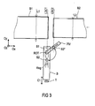
- Figure 3 shows an exemplary displacement device according to the invention adapted for a pre-step of cutting a tail and a band head (B1, B2) on said cutting lines (LDC1, LDC2), it is that is to say a cutting step preceding the welding step as performed by means of the displacement device presented to the figures 1 and 2 .
- the support (B) comprises at least one set of two cutting heads aligned in the Ox direction and spaced a distance equal to the distance from the cutting lines (LDC1, LDC2).
- the translator (T) by activating the translator (T) with a pass of the cutting heads over the full widths of the strips (B1, B2), it is possible to cut the tails and tape heads in order to guarantee any edge defects that could be detrimental to step subsequent welding.
- the displacement device according to the invention thus makes it possible to produce, in two successive passes, a step of cutting the two strips (B1, B2) (by two cutting heads under a first pass) and then a welding step (by the two welding heads S1, S2 under a second pass).
- the welding heads it is possible today for the welding heads to have, in addition to a welding mode, an alternative method of cutting the strip, ideally by laser means.
- the welding head (S1) fixed at the end of the support
- the welding head (S1) has such an alternative mode, it is therefore only necessary to add to the support a holding base of a single other cutting head according to the direction Ox and spaced apart from the distance between the cut lines (LDC1, LDC2).
- This embodiment is very advantageous because it does not require the addition of separate cutting heads on the support (B) in addition to the welding heads (S1, S2), the latter being activated in cutting mode.
- sub-module of displacement of the complementary head (S2) to the cutting line (LDC2) is a pivoting arm, but a person skilled in the art could of course consider any other form of submodule.
- the cutting is then simultaneously on head and tail bands in a single cutting pass of each of the cutting heads respectively on one of the cutting lines (LDC1, LDC2).
- the device according to the invention can provide that the welding heads are simply complemented by at least two tail cutting heads and tape head or switchable in a tail cutting mode and tape head, the cutting heads being they themselves coupled to the support so that, by moving the support in a cutting mode, each cutting head covers at least one width of the strips, namely the maximum width of the strips.
- the device according to the invention preferably provides that the welding and / or cutting heads comprise a laser output suitable for welding metal strips, said output being in particular coupled to a waveguide either optical fiber (so-called “asolide laser”) or aerial allowing a coupling of the guide to the laser output in synchronous displacement with the support when the translator (T), the submodule (PIV) and / or the adjustment (Reg) are activated.
- a laser supply of all the heads remains flexible even if the components of the displacement device according to the invention are moved to locking positions.
- the device according to the invention can also provide that the welding and / or cutting heads are coupled to their input to at least one laser source, via reduction of waveguides either to optical fiber (so-called “asolide laser”) or air.
- the welding and / or cutting heads are coupled to their input to at least one laser source, via reduction of waveguides either to optical fiber (so-called "asolide laser") or air.
- a welding method capable of welding a tail of a first metal strip with a second metal strip head can also be proposed, in particular very advantageous way for the two strips (B1, B2) running continuously (Def) in a metal treatment line comprising a band welder.
- the first and second strips are introduced into a welder comprising the displacement device according to the invention, and said device is activated in displacement for a minimum duration associated with a reduction of means for accumulating or unwinding strips, said means being located in accumulators located upstream and / or downstream of the welder, knowing that the welding time has been at least halved.
- the welding method provides that the device of displacement is coupled to successive phases of active welding to weld on discontinuous segments of bandwidth.
- the welding heads are activated only on said segments and inactivated between the segments.
- the displacement device then produces an acceleration of the translator so as to bring the welding heads more quickly to a next segment to be welded.
- a gain in welding time can be obtained.
- the welding method according to the invention also provides a cutting phase of the tail of the first metal strip and the head of the second metal strip being carried out before a welding phase by means of the displacement device.
- cutting heads are arranged on said device (support, sub-module).
- the welding method according to the invention can include cutting and welding phases which are done in only two passes, one go and one return above the band widths.
- the first "go" cutting pass is in the + Oy direction by means of cutting heads such as (S1, S2 ") according to figure 3
- the second "return” pass is made in the direction -Oy coming to arrange the complementary welding head (S2) in the middle of the band (B2) of minimum width and to arrange the welding head (S2) at the edge of the band (B2) at the top of the figure 3 .
- This arrangement of the welding heads can be performed when the tails and cut head of the two strips (B1, B2) are in the approach phase to finally allow welding.
- the same cycle can be repeated for all new bands in continuous scroll arriving in a welder governed by the method according to the invention.
Landscapes
- Physics & Mathematics (AREA)
- Optics & Photonics (AREA)
- Engineering & Computer Science (AREA)
- Plasma & Fusion (AREA)
- Mechanical Engineering (AREA)
- Laser Beam Processing (AREA)
Priority Applications (1)
| Application Number | Priority Date | Filing Date | Title |
|---|---|---|---|
| EP12290461.8A EP2745976A1 (de) | 2012-12-21 | 2012-12-21 | Vorrichtung zum Verschieben einer Anordnung zum Schweißen von Metallbändern |
Applications Claiming Priority (1)
| Application Number | Priority Date | Filing Date | Title |
|---|---|---|---|
| EP12290461.8A EP2745976A1 (de) | 2012-12-21 | 2012-12-21 | Vorrichtung zum Verschieben einer Anordnung zum Schweißen von Metallbändern |
Publications (1)
| Publication Number | Publication Date |
|---|---|
| EP2745976A1 true EP2745976A1 (de) | 2014-06-25 |
Family
ID=47603150
Family Applications (1)
| Application Number | Title | Priority Date | Filing Date |
|---|---|---|---|
| EP12290461.8A Withdrawn EP2745976A1 (de) | 2012-12-21 | 2012-12-21 | Vorrichtung zum Verschieben einer Anordnung zum Schweißen von Metallbändern |
Country Status (1)
| Country | Link |
|---|---|
| EP (1) | EP2745976A1 (de) |
Cited By (2)
| Publication number | Priority date | Publication date | Assignee | Title |
|---|---|---|---|---|
| CN111312786A (zh) * | 2020-02-28 | 2020-06-19 | 云谷(固安)科技有限公司 | 柔性显示面板及其制备方法 |
| CN119115969A (zh) * | 2024-11-15 | 2024-12-13 | 广州富士汽车整线集成有限公司 | 一种机器人动作控制方法和相关系统 |
Citations (2)
| Publication number | Priority date | Publication date | Assignee | Title |
|---|---|---|---|---|
| JPS60257983A (ja) * | 1984-06-04 | 1985-12-19 | Mitsubishi Electric Corp | レ−ザビ−ム溶接装置 |
| DE102007023017A1 (de) * | 2007-05-15 | 2008-11-20 | Thyssenkrupp Drauz Nothelfer Gmbh | Vorrichtung zum Herstellen von Tailored Blanks |
-
2012
- 2012-12-21 EP EP12290461.8A patent/EP2745976A1/de not_active Withdrawn
Patent Citations (2)
| Publication number | Priority date | Publication date | Assignee | Title |
|---|---|---|---|---|
| JPS60257983A (ja) * | 1984-06-04 | 1985-12-19 | Mitsubishi Electric Corp | レ−ザビ−ム溶接装置 |
| DE102007023017A1 (de) * | 2007-05-15 | 2008-11-20 | Thyssenkrupp Drauz Nothelfer Gmbh | Vorrichtung zum Herstellen von Tailored Blanks |
Cited By (3)
| Publication number | Priority date | Publication date | Assignee | Title |
|---|---|---|---|---|
| CN111312786A (zh) * | 2020-02-28 | 2020-06-19 | 云谷(固安)科技有限公司 | 柔性显示面板及其制备方法 |
| CN111312786B (zh) * | 2020-02-28 | 2022-11-15 | 云谷(固安)科技有限公司 | 柔性显示面板及其制备方法 |
| CN119115969A (zh) * | 2024-11-15 | 2024-12-13 | 广州富士汽车整线集成有限公司 | 一种机器人动作控制方法和相关系统 |
Similar Documents
| Publication | Publication Date | Title |
|---|---|---|
| EP3016776B1 (de) | Vorrichtung zum verschieben einer anordnung zum schneiden und schweissen von metallbändern ; verfahren zum schneiden und schweissen unter verwendeiner solchen vorrichtung | |
| FR2499033A1 (fr) | Procede et dispositif pour regulariser le transfert de produits solides identiques | |
| EP2205369B1 (de) | Vorrichtung zur prüfung eines blechstreifens | |
| FR2585486A1 (fr) | Appareil de commande de vitesses pour un appareillage de traitement en continu de toles d'acier | |
| EP2958687B1 (de) | Verfahren zum walzen eines blechstreifens | |
| EP2745976A1 (de) | Vorrichtung zum Verschieben einer Anordnung zum Schweißen von Metallbändern | |
| EP2013125B1 (de) | Verfahren und anlage zur inspektion eines gewickelten bands | |
| EP1591190A1 (de) | Verfahren zum Verschweissen zweier Metallbleche | |
| EP1917113B1 (de) | Überprüfungsverfahren | |
| FR2546378A1 (fr) | Procede et machine pour la fabrication simultanee de deux debits ou trains de cigarettes | |
| EP1577219B1 (de) | Vorrichtung zum Anbringen eines Tragegriffs | |
| EP1638708B1 (de) | Verfahren zur verwaltung einer endloslinienmetallbandverarbeitungsanlage und anlage zur durchführung dieses verfahrens | |
| EP1046606A1 (de) | Handlaufsvorrichtung eines beschleunigten Förderbands | |
| EP1375018B1 (de) | Bandführunsgvorichtung | |
| EP2664390B1 (de) | Ausgabeanlage und -verfahren einer Tandem-Walzstraße mit Haspelkarussell, gekoppelt mit einer Online-Inspektion | |
| FR3059655B1 (fr) | Distributeur d'adhesif et dispositif de raccordement de gaines comportant un tel distributeur | |
| WO2000073184A1 (fr) | Dispositif d'approvisionnement en papier, en particulier, pour une ligne de fabrication de carton | |
| EP3288880B1 (de) | Vorrichtung und verfahren zum einsetzen einer optischen faser in eine spule | |
| FR3081453A1 (fr) | Dispositif de transfert de produits, notamment pour le transfert de produits vers un poste recepteur a etages, et installation de manutention integrant un tel dispositif de transfert | |
| CA2861548A1 (fr) | Installation et procede de sortie de laminoir tandem avec carrousel de bobinage couplee avec une inspection en ligne | |
| FR3100006A1 (fr) | Système de dévidage d’un fil muni d’un dispositif de nettoyage dudit fil | |
| EP0820930B1 (de) | Umreifungsmaschine für Bandmaterialrollen | |
| WO2009150306A1 (fr) | Dispositif de cisaillage à la volée d'une bande d'acier pendant son défilement | |
| FR2901720A1 (fr) | Jeu de rouleaux tendeurs pour laminoir. | |
| FR2930463A1 (fr) | Dispositif de fabrication d'un tube helicoidal et procede associe |
Legal Events
| Date | Code | Title | Description |
|---|---|---|---|
| PUAI | Public reference made under article 153(3) epc to a published international application that has entered the european phase |
Free format text: ORIGINAL CODE: 0009012 |
|
| 17P | Request for examination filed |
Effective date: 20121221 |
|
| AK | Designated contracting states |
Kind code of ref document: A1 Designated state(s): AL AT BE BG CH CY CZ DE DK EE ES FI FR GB GR HR HU IE IS IT LI LT LU LV MC MK MT NL NO PL PT RO RS SE SI SK SM TR |
|
| AX | Request for extension of the european patent |
Extension state: BA ME |
|
| STAA | Information on the status of an ep patent application or granted ep patent |
Free format text: STATUS: THE APPLICATION IS DEEMED TO BE WITHDRAWN |
|
| 18D | Application deemed to be withdrawn |
Effective date: 20150106 |