EP2775536A2 - Panneau solaire et son procédé de fabrication - Google Patents
Panneau solaire et son procédé de fabrication Download PDFInfo
- Publication number
- EP2775536A2 EP2775536A2 EP14157762.7A EP14157762A EP2775536A2 EP 2775536 A2 EP2775536 A2 EP 2775536A2 EP 14157762 A EP14157762 A EP 14157762A EP 2775536 A2 EP2775536 A2 EP 2775536A2
- Authority
- EP
- European Patent Office
- Prior art keywords
- solar battery
- protection plate
- die
- back surface
- solar panel
- Prior art date
- Legal status (The legal status is an assumption and is not a legal conclusion. Google has not performed a legal analysis and makes no representation as to the accuracy of the status listed.)
- Granted
Links
Images



Classifications
-
- H—ELECTRICITY
- H10—SEMICONDUCTOR DEVICES; ELECTRIC SOLID-STATE DEVICES NOT OTHERWISE PROVIDED FOR
- H10F—INORGANIC SEMICONDUCTOR DEVICES SENSITIVE TO INFRARED RADIATION, LIGHT, ELECTROMAGNETIC RADIATION OF SHORTER WAVELENGTH OR CORPUSCULAR RADIATION
- H10F19/00—Integrated devices, or assemblies of multiple devices, comprising at least one photovoltaic cell covered by group H10F10/00, e.g. photovoltaic modules
- H10F19/80—Encapsulations or containers for integrated devices, or assemblies of multiple devices, having photovoltaic cells
-
- H—ELECTRICITY
- H10—SEMICONDUCTOR DEVICES; ELECTRIC SOLID-STATE DEVICES NOT OTHERWISE PROVIDED FOR
- H10F—INORGANIC SEMICONDUCTOR DEVICES SENSITIVE TO INFRARED RADIATION, LIGHT, ELECTROMAGNETIC RADIATION OF SHORTER WAVELENGTH OR CORPUSCULAR RADIATION
- H10F19/00—Integrated devices, or assemblies of multiple devices, comprising at least one photovoltaic cell covered by group H10F10/00, e.g. photovoltaic modules
- H10F19/80—Encapsulations or containers for integrated devices, or assemblies of multiple devices, having photovoltaic cells
- H10F19/807—Double-glass encapsulation, e.g. photovoltaic cells arranged between front and rear glass sheets
-
- B—PERFORMING OPERATIONS; TRANSPORTING
- B60—VEHICLES IN GENERAL
- B60K—ARRANGEMENT OR MOUNTING OF PROPULSION UNITS OR OF TRANSMISSIONS IN VEHICLES; ARRANGEMENT OR MOUNTING OF PLURAL DIVERSE PRIME-MOVERS IN VEHICLES; AUXILIARY DRIVES FOR VEHICLES; INSTRUMENTATION OR DASHBOARDS FOR VEHICLES; ARRANGEMENTS IN CONNECTION WITH COOLING, AIR INTAKE, GAS EXHAUST OR FUEL SUPPLY OF PROPULSION UNITS IN VEHICLES
- B60K16/00—Arrangements in connection with power supply of propulsion units in vehicles from forces of nature, e.g. sun or wind
- B60K2016/003—Arrangements in connection with power supply of propulsion units in vehicles from forces of nature, e.g. sun or wind solar power driven
-
- B—PERFORMING OPERATIONS; TRANSPORTING
- B62—LAND VEHICLES FOR TRAVELLING OTHERWISE THAN ON RAILS
- B62D—MOTOR VEHICLES; TRAILERS
- B62D25/00—Superstructure or monocoque structure sub-units; Parts or details thereof not otherwise provided for
- B62D25/06—Fixed roofs
-
- H—ELECTRICITY
- H02—GENERATION; CONVERSION OR DISTRIBUTION OF ELECTRIC POWER
- H02S—GENERATION OF ELECTRIC POWER BY CONVERSION OF INFRARED RADIATION, VISIBLE LIGHT OR ULTRAVIOLET LIGHT, e.g. USING PHOTOVOLTAIC [PV] MODULES
- H02S10/00—PV power plants; Combinations of PV energy systems with other systems for the generation of electric power
- H02S10/40—Mobile PV generator systems
-
- Y—GENERAL TAGGING OF NEW TECHNOLOGICAL DEVELOPMENTS; GENERAL TAGGING OF CROSS-SECTIONAL TECHNOLOGIES SPANNING OVER SEVERAL SECTIONS OF THE IPC; TECHNICAL SUBJECTS COVERED BY FORMER USPC CROSS-REFERENCE ART COLLECTIONS [XRACs] AND DIGESTS
- Y02—TECHNOLOGIES OR APPLICATIONS FOR MITIGATION OR ADAPTATION AGAINST CLIMATE CHANGE
- Y02E—REDUCTION OF GREENHOUSE GAS [GHG] EMISSIONS, RELATED TO ENERGY GENERATION, TRANSMISSION OR DISTRIBUTION
- Y02E10/00—Energy generation through renewable energy sources
- Y02E10/50—Photovoltaic [PV] energy
Definitions
- the present invention relates to a solar panel and a method for manufacturing the same.
- a known solar panel is disclosed in Toyota Motor Corporation website "toyota.jp PRIUS
- a solar panel 82 is used in a roof 81 of a vehicle 80.
- the solar panel 82 is composed of a protection plate 90, a plurality of solar battery cells 91, an encapsulant 92 and a film 93.
- the protection plate 90 is formed from inorganic glass having translucency from a front surface 90a that serves as a design surface to a back surface 90b.
- the respective solar battery cells 91 adopt crystalline silicon and are formed into flat plate shapes.
- the encapsulant 92 is integrally provided on the back surface 90b of the protection plate 90.
- the encapsulant 92 fixes the respective solar battery cells 91 to the back surface 90b of the protection plate 90 in sealed state.
- the film 93 is provided on a back surface of the encapsulant 92.
- the solar panel 82 forms a solar ventilation system in the vehicle 80.
- the solar panel 82 can supply, among other purposes, electric power for ventilating a vehicle interior while the vehicle 80 is parked, for example, in the summer season.
- the solar panel 82 is manufactured substantially as follows. First, inorganic glass in a flat plate shape is prepared. Subsequently, the inorganic glass is heated to be bent into the protection plate 90. In the protection plate 90, the front surface 90a serves as the design surface along the roof 81. Subsequently, an encapsulant 92a is disposed on the back surface 90b of the protection plate 90, the respective solar battery cells 91 are disposed next, and an encapsulant 92b is disposed on the back surfaces of the respective solar battery cells 91. In this manner, the encapsulant 92 is provided on the back surface 90b of the protection plate 90.
- the film 93 is provided on the back surface of the encapsulant 92b, and thereafter, the encapsulants 92a and 92b are brought into close contact with each other.
- the respective solar battery cells 91 are fixed to the back surface 90b in sealed state by the encapsulant 92.
- the protection plate 90 in the above solar panels may be difficult to form in the manufacturing process.
- the present invention has been made in the light of the conventional circumstances described above, and an object thereof is to provide a solar panel capable of exhibiting excellent aesthetics and power generation efficiency, and capable of easily forming in a manufacturing process.
- a solar panel of the present invention comprises a protection plate that has translucency from a front surface to a back surface, a solar battery cell, and an encapsulant that is integrally provided on the back surface and fixes the solar battery cell to the back surface in sealed state.
- the protection plate is formed from a resin.
- the front surface serves as a design surface.
- a portion of the back surface that faces the solar battery cell serves as an offset surface that is offset with respect to the solar battery cell, and differs from the design surface in shape.
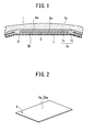
- a solar panel of embodiment 1 is composed of a protection plate 1, a plurality of solar battery cells 3, an encapsulant 5 and a film 7.
- the protection plate 1 has polycarbonate as a main component.
- the protection plate 1 has translucency from a front surface 1a that serves as a design surface to a back surface 1b.
- crystalline silicon is adopted as the respective solar battery cells 3.
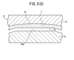
- cell surfaces 3a are flat surfaces in ordinary state.
- the encapsulant 5 is integrally provided on the back surface 1b of the protection plate 1.
- the encapsulant 5 fixes the respective solar battery cells 3 to the back surface 1b in sealed state.
- the film 7 is provided on a back surface of the encapsulant 5.
- the back surface 1b of the protection plate 1 is composed of offset surfaces 1c that face the respective solar battery cells 3, and bending surfaces 1d that connect the respective offset surfaces 1c.
- the offset surface 1c differs from the design surface of the front surface 1a of the protection plate 1, and forms flatness that is offset with respect to the cell surface 3a of the solar battery cell 3.
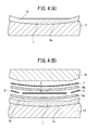
- the solar panel is manufactured as follows. First, as shown in FIG. 3(A) , as a preparation step, a molding die 11 is prepared.
- the molding die 11 has a first die 13 and a second die 15.
- a first molding surface 13a capable of molding the front surface 1a of the protection plate 1 is formed.
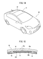
- the first molding surface 13a bends along a roof 81, as shown in FIG. 14 .
- a second molding surface 15a that faces the first molding surface 13a is formed.
- the second molding surface 15a is capable of molding the offset surface 1c and the curved surface 1d of the protection plate 1.
- a gate not illustrated communicates with the cavity C1.
- a molten resin P1 with polycarbonate as a main component is injected into the cavity C1.
- the molding die 11 is opened. In this manner, the protection plate 1 with polycarbonate as the main component is molded.
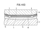
- a vacuum forming jig 17 and a force plunger 18 are prepared, in place of the molding die 11.
- the vacuum forming jig 17 holds the front surface 1a so as to cause the back surface 1b of the protection plate 1 to face upward.
- the sheet-shaped encapsulant 5a, the respective solar battery cells 3, a sheet-shaped encapsulant 5b, and a film 7 are disposed in sequence on the back surface 1b of the protection plate 1.
- the vacuum forming jig 17 and the force plunger 18 bring clearances between the respective members into vacuum state while pressing the respective members.
- the encapsulant 5 is softened by heating, and brings the respective members into close contact with the encapsulant 5.
- the respective solar battery cells 3 are fixed to the back surface 1b in the sealed state.
- the solar panel As shown in FIG. 5 , in the solar panel that is obtained in this manner, an entire structure and the front surface 1a (the design surface) of the protection plate 1 are formed into a dome shape, and all the offset surfaces 1c and the cell surfaces 3a are flat surfaces.
- the solar panel also forms a solar ventilation system in a vehicle similarly to the conventional solar panel.
- the solar panel also can supply electric power or the like for ventilating a vehicle interior while the vehicle is parked in the summer season or the like.
- the protection plate 1 is easily formed from a resin by injection molding.
- the front surface 1a serves as a design surface similarly to the conventional solar panel.
- portions of the back surface 1b that face the respective solar battery cells 3 are offset with respect to the solar battery cells 3, and serve as the flat offset surfaces 1c that differ from the design surface in shape. Therefore, a distance between the offset surface 1c and the solar battery cell 3 does not vary in a width direction of the solar battery cell 3. Therefore, when the encapsulant 5 is provided on the back surface 1b of the protection plate 1, adhesion between the protection plate 1 and the solar battery cell 3 is high, and the encapsulant 5 between the back surface 1b and the solar battery cell 3 is less likely to contain air bubbles.
- the solar battery cell 3 since in the sealed state, the solar battery cell 3 is pressed against the offset surface 1c of the protection plate 1, bending force is less likely to be applied to the solar battery cell 3. Therefore, the solar battery cell 3 is less likely to crack in despite of press by the force plunger 18, and power generation efficiency is less likely to be impaired.
- the solar panel is capable of exhibiting excellent aesthetics and power generation efficiency, and is capable of preventing cracking of the solar battery cell 3 in the manufacturing process.
- the respective offset surfaces 1c are connected by the bending surfaces 1d. Therefore, straight line portions that are formed when the respective offset surfaces 1c intersect one another to connect to one another are not visible from the solar panel, and the solar panel exhibits excellent outer appearance.
- a solar panel of embodiment 2 is composed of a protection plate 21, a plurality of solar battery cells 23, the encapsulant 5 and the film 7.
- the protection plate 21 has polycarbonate as a main component.
- the protection plate 21 has translucency from a front surface 21a that serves as a design surface to a back surface 21b.
- crystalline silicon is adopted.
- Each of the solar battery cells 23, which is flat in the cell surface 3a in ordinary state as shown in FIG. 2 has flexibility capable of bending in one direction.
- the cell surface that is bent to be a curved surface is assigned with reference sign 23a.
- the encapsulant 5 is integrally provided on the back surface 21b of the protection plate 21.
- the encapsulant 5 fixes the respective solar battery cells 23 to the back surface 21b in sealed state.
- the film 7 is provided on a back surface of the encapsulant 5.
- the back surface 21b of the protection plate 21 is composed of offset surfaces 21c that face the respective solar battery cells 23, and curved surfaces 21d that connect the respective offset surfaces 21c.
- the offset surface 21c differs from the front surface 21a of the protection plate 21, and forms a curved surface that is offset with respect to the cell surface 23a of the solar battery cell 23.
- the solar panel is manufactured as follows. First, as shown in FIG. 7(A) , a molding die 31 is prepared as a preparation step.
- the molding die 31 has a first die 33 and a second die 35.
- first molding surface 33a capable of molding the front surface 21a of the protection plate 21 is formed.
- second molding surface 35a that faces the first molding surface 33a is formed.
- the second molding surface 35a is capable of molding the offset surfaces 21c and the curved surfaces 21d of the protection plate 21.
- a molten resin P2 with polycarbonate as a main component is injected into the cavity C2.
- the molding die 31 is opened after the molten resin P2 is solidified.
- the protection plate 21 with polycarbonate as a main component is molded.
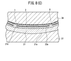
- a vacuum forming jig 37 and a force plunger 38 are prepared, as shown in FIGS. 8(A) to 8(C) .
- the vacuum forming jig 37 holds the front surface 21a so as to cause the back surface 21b of the protection plate 21 to face upward.
- a sheet-shaped encapsulant 5a, the respective solar battery cells 3, a sheet-shaped encapsulant 5b, and the film 7 are disposed in sequence on the back surface 21b of the protection plate 21.
- the vacuum forming jig 37 and the force plunger 38 bring clearances between the respective members into vacuum state while pressing the respective members.
- the encapsulants 5a and 5b are softened by heating to bring the respective members into close contact therewith.
- the respective solar battery cells 3 are fixed to the back surface 21b in sealed state.
- the respective solar battery cells 3 become the solar battery cells 23 that have the cell surfaces 23a that are the curved surfaces similarly to the back surface 21b by pressing by the force plunger 38.
- all the offset surfaces 21c and the cell surfaces 23a are curved surfaces as shown in FIG. 9 , and the entire structure and the front surface 21a (the design surface) of the protection plate 21 are in a dome shape.
- the solar panel is in the shape that more easily conforms to the ceiling surface of a vehicle than that of embodiment 1.
- the other operations and effects are similar to those in embodiment 1.
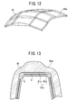
- a solar panel of embodiment 3 is composed of a protection plate 61, the plurality of solar battery cells 3, and the encapsulant 5.
- the protection plate 61 has a synthetic resin as a main component.
- the protection plate 61 has translucency from a front surface 61a that serves as a design surface to a back surface 61b.
- the respective solar battery cells 3 are formed into flat plate shapes.
- the encapsulant 5 is integrally provided on the back surface 61b of the protection plate 61. The encapsulant 5 fixes the respective solar battery cells 3 to the back surface 61b in sealed state.
- the back surface 61b of the protection plate 61 is also composed of flat offset surfaces 61c that face the respective solar battery cells 3 and differ from the front surface 61a, and curved surfaces 61d that connect the respective offset surfaces 61c.
- the front surface 61a that is the design surface has a three-dimensional shape that is more complicated than those in embodiments 1 and 2, but the solar panel provides the operation and effect similar to those of embodiments 1 and 2.
- a solar panel also can be composed of the cell surfaces 3a formed by flat surfaces and the cell surfaces 23a formed by curved surfaces.
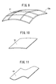
- the solar panel of the present invention may adopt a solar battery cell 33 that is formed into a curved surface shape in advance.
- the solar panel of the present invention may adopt a solar battery cell 43 that is formed in a ruffled shape in advance.
- the solar panel of the present invention may use a protection plate 51 that is formed by offset surfaces and cell surfaces 53a that are formed by various curved surfaces such as a part of a cylindrical surface, a part of a conical surface, a surface with a parabolic section, and a surface with a section in a ruffled shape, and has an entire structure and a front surface (a design surface) formed into a dome shape.
- the present invention is usable in a roof of a vehicle, or the like.
- the solar panel of the present invention comprises a protection plate 1 having translucency from a front surface 1a to a back surface, a solar battery cell, and an encapsulant that is integrally provided on the back surface, and fixes the solar battery cell to the back surface in sealed state.
- the protection plate is formed from a resin with polycarbonate as a main component by injection molding.
- the front surface serves as a design surface.
- a portion of the back surface that faces the solar battery cell serves as an offset surface that is offset with respect to the solar battery cell, and differs from the design surface in shape.
Landscapes
- Photovoltaic Devices (AREA)
- Laminated Bodies (AREA)
- Injection Moulding Of Plastics Or The Like (AREA)
Applications Claiming Priority (3)
| Application Number | Priority Date | Filing Date | Title |
|---|---|---|---|
| JP2013046903 | 2013-03-08 | ||
| JP2013099829 | 2013-05-10 | ||
| JP2014033202A JP5804106B2 (ja) | 2013-03-08 | 2014-02-24 | ソーラーパネル |
Publications (3)
| Publication Number | Publication Date |
|---|---|
| EP2775536A2 true EP2775536A2 (fr) | 2014-09-10 |
| EP2775536A3 EP2775536A3 (fr) | 2014-10-01 |
| EP2775536B1 EP2775536B1 (fr) | 2019-09-25 |
Family
ID=50235969
Family Applications (1)
| Application Number | Title | Priority Date | Filing Date |
|---|---|---|---|
| EP14157762.7A Active EP2775536B1 (fr) | 2013-03-08 | 2014-03-05 | Panneau solaire et son procédé de fabrication |
Country Status (3)
| Country | Link |
|---|---|
| US (1) | US9419163B2 (fr) |
| EP (1) | EP2775536B1 (fr) |
| JP (1) | JP5804106B2 (fr) |
Cited By (3)
| Publication number | Priority date | Publication date | Assignee | Title |
|---|---|---|---|---|
| EP3360762A1 (fr) * | 2017-02-08 | 2018-08-15 | Toyota Jidosha Kabushiki Kaisha | Structure supérieure de carrosserie de véhicule |
| EP3421333A4 (fr) * | 2017-03-24 | 2019-04-17 | Beijing Apollo Ding Rong Solar Technology Co., Ltd. | Ensemble film mince solaire pour toit de voiture et voiture solaire |
| NL2023851B1 (en) * | 2019-09-18 | 2021-05-18 | Atlas Technologies Holding Bv | Solar panel curved in two direction |
Families Citing this family (13)
| Publication number | Priority date | Publication date | Assignee | Title |
|---|---|---|---|---|
| JP5834201B2 (ja) * | 2013-04-10 | 2015-12-16 | パナソニックIpマネジメント株式会社 | 太陽電池装置およびその製造方法 |
| JP5835375B2 (ja) * | 2014-02-27 | 2015-12-24 | トヨタ自動車株式会社 | 太陽電池搭載構造 |
| JP6380181B2 (ja) * | 2015-03-18 | 2018-08-29 | トヨタ自動車株式会社 | 太陽電池モジュール |
| DK178881B1 (en) * | 2015-08-27 | 2017-04-24 | Axmetic-Engineering V/Jan Mahler | A method for manufacturing a solar cell panel and a solar cell panel manufactured using such a method |
| JP6434895B2 (ja) * | 2015-11-30 | 2018-12-05 | トヨタ自動車株式会社 | 太陽電池モジュール |
| ES2899362T3 (es) * | 2017-07-26 | 2022-03-11 | Sono Motors Gmbh | Parte de carrocería y procedimiento para fabricar una parte de carrocería |
| JP6779197B2 (ja) * | 2017-12-13 | 2020-11-04 | 株式会社豊田自動織機 | ソーラーパネルの製造方法 |
| KR102233877B1 (ko) * | 2019-04-01 | 2021-03-30 | 엘지전자 주식회사 | 태양 전지 패널 및 이의 제조 방법 |
| FR3131982B1 (fr) * | 2022-01-14 | 2025-05-02 | Commissariat Energie Atomique | Procédé de fabrication d’un module photovoltaïque et installation de fabrication correspondante |
| EP4394896A1 (fr) * | 2022-12-30 | 2024-07-03 | Sono Motors GmbH | Procédé et dispositif de fabrication d'un panneau photovoltaïque comprenant un agencement de cellules solaires par moulage par injection-compression |
| DE102023107284A1 (de) | 2023-03-23 | 2024-09-26 | Audi Aktiengesellschaft | Solarzellenmodul für ein Kraftfahrzeug, Kraftfahrzeug und Verfahren zum Herstellen eines Solarzellenmoduls |
| DE102023107283A1 (de) | 2023-03-23 | 2024-09-26 | Audi Aktiengesellschaft | Solarzellenmodul für ein Kraftfahrzeug, Kraftfahrzeug und Verfahren zum Herstellen eines Solarzellenmoduls |
| JP2025158540A (ja) * | 2024-04-05 | 2025-10-17 | トヨタ自動車株式会社 | 太陽電池モジュール、および太陽電池モジュールの製造方法 |
Family Cites Families (16)
| Publication number | Priority date | Publication date | Assignee | Title |
|---|---|---|---|---|
| US3565719A (en) * | 1967-05-17 | 1971-02-23 | Nasa | Solar panel fabrication |
| DE3538986C3 (de) * | 1985-11-02 | 1994-11-24 | Deutsche Aerospace | Verfahren zur Herstellung eines Solargenerators |
| JPH0610703Y2 (ja) | 1986-01-31 | 1994-03-16 | 京セラ株式会社 | 太陽電池モジユ−ル |
| DE68911201T2 (de) * | 1988-05-24 | 1994-06-16 | Asahi Glass Co Ltd | Methode für die Herstellung eines Solarzellenglassubstrates. |
| CH683730A5 (de) * | 1991-09-06 | 1994-04-29 | Troesch Glas Ag | Verfahren zum Herstellen eines photovoltaischen Solarmoduls. |
| JP2002270881A (ja) | 2001-03-08 | 2002-09-20 | Nissan Motor Co Ltd | 太陽電池パネルおよびその製造方法 |
| WO2002086977A1 (fr) * | 2001-04-23 | 2002-10-31 | Carmanah Technologies Inc. | Capsule d'enrobage en forme de dome pour panneau solaire et feux de signalisation routiere comportant ladite capsule |
| WO2003005457A1 (fr) * | 2001-07-04 | 2003-01-16 | Ebara Corporation | Module a piles solaires et procede permettant sa realisation |
| DE102004003328B4 (de) * | 2004-01-22 | 2006-11-09 | Webasto Ag | Verfahren zum Herstellen eines gewölbten Karosserieelements mit Solarzellen |
| WO2009108874A2 (fr) * | 2008-02-27 | 2009-09-03 | Solar Roofing Systems, Inc. | Procédé de fabrication de tuiles photovoltaïques et tuiles photovoltaïques |
| JP4986503B2 (ja) * | 2005-11-08 | 2012-07-25 | 富士通コンポーネント株式会社 | 熱可塑性樹脂筐体及びその製造方法 |
| DE102008038647B4 (de) * | 2008-08-12 | 2017-10-19 | Webasto SE | Fahrzeugflächenbauteil mit einer Solarzellenanordnung |
| DE102009035733A1 (de) * | 2009-08-01 | 2011-02-03 | Daimler Ag | Baukastensystem und Verfahren zum Herstellen eines Dachmoduls |
| US8633051B2 (en) * | 2009-08-24 | 2014-01-21 | Semiconductor Energy Laboratory Co., Ltd. | Semiconductor device and method for manufacturing semiconductor device |
| KR101085475B1 (ko) * | 2009-12-21 | 2011-11-21 | 삼성전기주식회사 | 태양전지모듈 및 그 제조방법 |
| US20130160824A1 (en) * | 2011-12-21 | 2013-06-27 | Solopower, Inc. | Roof integrated solar module assembly |
-
2014
- 2014-02-24 JP JP2014033202A patent/JP5804106B2/ja not_active Expired - Fee Related
- 2014-03-05 EP EP14157762.7A patent/EP2775536B1/fr active Active
- 2014-03-07 US US14/200,823 patent/US9419163B2/en not_active Expired - Fee Related
Non-Patent Citations (1)
| Title |
|---|
| "toyota.jp PRIUS |FUNCTION/MECHANISM BODY", TOYOTA MOTOR CORPORATION |
Cited By (4)
| Publication number | Priority date | Publication date | Assignee | Title |
|---|---|---|---|---|
| EP3360762A1 (fr) * | 2017-02-08 | 2018-08-15 | Toyota Jidosha Kabushiki Kaisha | Structure supérieure de carrosserie de véhicule |
| US10293867B2 (en) | 2017-02-08 | 2019-05-21 | Toyota Jidosha Kabushiki Kaisha | Vehicle body upper structure |
| EP3421333A4 (fr) * | 2017-03-24 | 2019-04-17 | Beijing Apollo Ding Rong Solar Technology Co., Ltd. | Ensemble film mince solaire pour toit de voiture et voiture solaire |
| NL2023851B1 (en) * | 2019-09-18 | 2021-05-18 | Atlas Technologies Holding Bv | Solar panel curved in two direction |
Also Published As
| Publication number | Publication date |
|---|---|
| US20140251415A1 (en) | 2014-09-11 |
| JP2014239206A (ja) | 2014-12-18 |
| EP2775536A3 (fr) | 2014-10-01 |
| US9419163B2 (en) | 2016-08-16 |
| EP2775536B1 (fr) | 2019-09-25 |
| JP5804106B2 (ja) | 2015-11-04 |
Similar Documents
| Publication | Publication Date | Title |
|---|---|---|
| EP2775536B1 (fr) | Panneau solaire et son procédé de fabrication | |
| EP3282489B1 (fr) | Module photovoltaïque | |
| RU2299808C2 (ru) | Способ производства пластикового оконного стекла с электропроводящей структурой и пластикового оконного стекла с заделанными проволоками | |
| EP3070749B1 (fr) | Panneau solaire | |
| CN113614927A (zh) | 一种用于制造光伏模块的方法 | |
| JP5914803B2 (ja) | インモールド成形方法、及びインモールド成形装置 | |
| US10615300B2 (en) | Method for manufacturing solar panel | |
| US20140193702A1 (en) | Housing for a Galvanic Element | |
| JPH03204979A (ja) | 太陽電池モジュール及びその製造方法 | |
| US20170092795A1 (en) | Interconnector and solar panel | |
| JP2019209614A (ja) | 樹脂枠体付き板状体の製造方法、および樹脂枠体付き板状体 | |
| CN102320135A (zh) | 设有嵌件的塑料体的制造方法 | |
| CN111845301A (zh) | 一种新型外水切亮条结构及其制造方法、车辆 | |
| JP7610793B2 (ja) | 車両窓用樹脂枠体付きガラス | |
| CN207449805U (zh) | 一种用于客车发动机舱门的消音隔热板 | |
| CN209096646U (zh) | 一种超声波焊接饰条 | |
| CN202391292U (zh) | 一种整体式注塑成型的玻璃门壳 | |
| CN220065457U (zh) | 一种操作元件 | |
| EP4394896A1 (fr) | Procédé et dispositif de fabrication d'un panneau photovoltaïque comprenant un agencement de cellules solaires par moulage par injection-compression | |
| US20090305001A1 (en) | Housing for electronic device and method for making the housing | |
| WO2013110380A1 (fr) | Photovoltaïque organique sur des surfaces à forme libre | |
| CN210429838U (zh) | 具有安装槽的光伏组件及光伏建筑幕墙 | |
| CN111988933A (zh) | 具有软硬材质的壳体、制作壳体的方法和电子装置 | |
| CN206012291U (zh) | 一种组件 | |
| CN106760410B (zh) | 装饰封板及其加工工艺 |
Legal Events
| Date | Code | Title | Description |
|---|---|---|---|
| PUAL | Search report despatched |
Free format text: ORIGINAL CODE: 0009013 |
|
| PUAI | Public reference made under article 153(3) epc to a published international application that has entered the european phase |
Free format text: ORIGINAL CODE: 0009012 |
|
| 17P | Request for examination filed |
Effective date: 20140305 |
|
| AK | Designated contracting states |
Kind code of ref document: A2 Designated state(s): AL AT BE BG CH CY CZ DE DK EE ES FI FR GB GR HR HU IE IS IT LI LT LU LV MC MK MT NL NO PL PT RO RS SE SI SK SM TR |
|
| AX | Request for extension of the european patent |
Extension state: BA ME |
|
| AK | Designated contracting states |
Kind code of ref document: A3 Designated state(s): AL AT BE BG CH CY CZ DE DK EE ES FI FR GB GR HR HU IE IS IT LI LT LU LV MC MK MT NL NO PL PT RO RS SE SI SK SM TR |
|
| AX | Request for extension of the european patent |
Extension state: BA ME |
|
| RIC1 | Information provided on ipc code assigned before grant |
Ipc: H01L 31/048 20140101AFI20140822BHEP Ipc: B62D 25/06 20060101ALI20140822BHEP Ipc: B60K 16/00 20060101ALN20140822BHEP Ipc: H01L 31/18 20060101ALI20140822BHEP |
|
| STAA | Information on the status of an ep patent application or granted ep patent |
Free format text: STATUS: EXAMINATION IS IN PROGRESS |
|
| 17Q | First examination report despatched |
Effective date: 20170203 |
|
| RIC1 | Information provided on ipc code assigned before grant |
Ipc: B60K 16/00 20060101ALN20190115BHEP Ipc: H01L 31/048 20140101AFI20190115BHEP Ipc: B62D 25/06 20060101ALI20190115BHEP Ipc: H01L 31/18 20060101ALI20190115BHEP |
|
| GRAP | Despatch of communication of intention to grant a patent |
Free format text: ORIGINAL CODE: EPIDOSNIGR1 |
|
| STAA | Information on the status of an ep patent application or granted ep patent |
Free format text: STATUS: GRANT OF PATENT IS INTENDED |
|
| INTG | Intention to grant announced |
Effective date: 20190412 |
|
| RIC1 | Information provided on ipc code assigned before grant |
Ipc: B60K 16/00 20060101ALN20190401BHEP Ipc: H01L 31/048 20140101AFI20190401BHEP Ipc: B62D 25/06 20060101ALI20190401BHEP Ipc: H01L 31/18 20060101ALI20190401BHEP |
|
| GRAS | Grant fee paid |
Free format text: ORIGINAL CODE: EPIDOSNIGR3 |
|
| GRAA | (expected) grant |
Free format text: ORIGINAL CODE: 0009210 |
|
| STAA | Information on the status of an ep patent application or granted ep patent |
Free format text: STATUS: THE PATENT HAS BEEN GRANTED |
|
| AK | Designated contracting states |
Kind code of ref document: B1 Designated state(s): AL AT BE BG CH CY CZ DE DK EE ES FI FR GB GR HR HU IE IS IT LI LT LU LV MC MK MT NL NO PL PT RO RS SE SI SK SM TR |
|
| REG | Reference to a national code |
Ref country code: GB Ref legal event code: FG4D |
|
| REG | Reference to a national code |
Ref country code: CH Ref legal event code: EP |
|
| REG | Reference to a national code |
Ref country code: AT Ref legal event code: REF Ref document number: 1184683 Country of ref document: AT Kind code of ref document: T Effective date: 20191015 |
|
| REG | Reference to a national code |
Ref country code: IE Ref legal event code: FG4D |
|
| REG | Reference to a national code |
Ref country code: DE Ref legal event code: R096 Ref document number: 602014054112 Country of ref document: DE |
|
| REG | Reference to a national code |
Ref country code: NL Ref legal event code: MP Effective date: 20190925 |
|
| PG25 | Lapsed in a contracting state [announced via postgrant information from national office to epo] |
Ref country code: NO Free format text: LAPSE BECAUSE OF FAILURE TO SUBMIT A TRANSLATION OF THE DESCRIPTION OR TO PAY THE FEE WITHIN THE PRESCRIBED TIME-LIMIT Effective date: 20191225 Ref country code: BG Free format text: LAPSE BECAUSE OF FAILURE TO SUBMIT A TRANSLATION OF THE DESCRIPTION OR TO PAY THE FEE WITHIN THE PRESCRIBED TIME-LIMIT Effective date: 20191225 Ref country code: SE Free format text: LAPSE BECAUSE OF FAILURE TO SUBMIT A TRANSLATION OF THE DESCRIPTION OR TO PAY THE FEE WITHIN THE PRESCRIBED TIME-LIMIT Effective date: 20190925 Ref country code: HR Free format text: LAPSE BECAUSE OF FAILURE TO SUBMIT A TRANSLATION OF THE DESCRIPTION OR TO PAY THE FEE WITHIN THE PRESCRIBED TIME-LIMIT Effective date: 20190925 Ref country code: FI Free format text: LAPSE BECAUSE OF FAILURE TO SUBMIT A TRANSLATION OF THE DESCRIPTION OR TO PAY THE FEE WITHIN THE PRESCRIBED TIME-LIMIT Effective date: 20190925 Ref country code: LT Free format text: LAPSE BECAUSE OF FAILURE TO SUBMIT A TRANSLATION OF THE DESCRIPTION OR TO PAY THE FEE WITHIN THE PRESCRIBED TIME-LIMIT Effective date: 20190925 |
|
| REG | Reference to a national code |
Ref country code: LT Ref legal event code: MG4D |
|
| PG25 | Lapsed in a contracting state [announced via postgrant information from national office to epo] |
Ref country code: LV Free format text: LAPSE BECAUSE OF FAILURE TO SUBMIT A TRANSLATION OF THE DESCRIPTION OR TO PAY THE FEE WITHIN THE PRESCRIBED TIME-LIMIT Effective date: 20190925 Ref country code: GR Free format text: LAPSE BECAUSE OF FAILURE TO SUBMIT A TRANSLATION OF THE DESCRIPTION OR TO PAY THE FEE WITHIN THE PRESCRIBED TIME-LIMIT Effective date: 20191226 Ref country code: RS Free format text: LAPSE BECAUSE OF FAILURE TO SUBMIT A TRANSLATION OF THE DESCRIPTION OR TO PAY THE FEE WITHIN THE PRESCRIBED TIME-LIMIT Effective date: 20190925 |
|
| REG | Reference to a national code |
Ref country code: AT Ref legal event code: MK05 Ref document number: 1184683 Country of ref document: AT Kind code of ref document: T Effective date: 20190925 |
|
| PG25 | Lapsed in a contracting state [announced via postgrant information from national office to epo] |
Ref country code: PT Free format text: LAPSE BECAUSE OF FAILURE TO SUBMIT A TRANSLATION OF THE DESCRIPTION OR TO PAY THE FEE WITHIN THE PRESCRIBED TIME-LIMIT Effective date: 20200127 Ref country code: ES Free format text: LAPSE BECAUSE OF FAILURE TO SUBMIT A TRANSLATION OF THE DESCRIPTION OR TO PAY THE FEE WITHIN THE PRESCRIBED TIME-LIMIT Effective date: 20190925 Ref country code: RO Free format text: LAPSE BECAUSE OF FAILURE TO SUBMIT A TRANSLATION OF THE DESCRIPTION OR TO PAY THE FEE WITHIN THE PRESCRIBED TIME-LIMIT Effective date: 20190925 Ref country code: NL Free format text: LAPSE BECAUSE OF FAILURE TO SUBMIT A TRANSLATION OF THE DESCRIPTION OR TO PAY THE FEE WITHIN THE PRESCRIBED TIME-LIMIT Effective date: 20190925 Ref country code: EE Free format text: LAPSE BECAUSE OF FAILURE TO SUBMIT A TRANSLATION OF THE DESCRIPTION OR TO PAY THE FEE WITHIN THE PRESCRIBED TIME-LIMIT Effective date: 20190925 Ref country code: AT Free format text: LAPSE BECAUSE OF FAILURE TO SUBMIT A TRANSLATION OF THE DESCRIPTION OR TO PAY THE FEE WITHIN THE PRESCRIBED TIME-LIMIT Effective date: 20190925 Ref country code: PL Free format text: LAPSE BECAUSE OF FAILURE TO SUBMIT A TRANSLATION OF THE DESCRIPTION OR TO PAY THE FEE WITHIN THE PRESCRIBED TIME-LIMIT Effective date: 20190925 Ref country code: AL Free format text: LAPSE BECAUSE OF FAILURE TO SUBMIT A TRANSLATION OF THE DESCRIPTION OR TO PAY THE FEE WITHIN THE PRESCRIBED TIME-LIMIT Effective date: 20190925 |
|
| PG25 | Lapsed in a contracting state [announced via postgrant information from national office to epo] |
Ref country code: IS Free format text: LAPSE BECAUSE OF FAILURE TO SUBMIT A TRANSLATION OF THE DESCRIPTION OR TO PAY THE FEE WITHIN THE PRESCRIBED TIME-LIMIT Effective date: 20200224 Ref country code: SM Free format text: LAPSE BECAUSE OF FAILURE TO SUBMIT A TRANSLATION OF THE DESCRIPTION OR TO PAY THE FEE WITHIN THE PRESCRIBED TIME-LIMIT Effective date: 20190925 Ref country code: SK Free format text: LAPSE BECAUSE OF FAILURE TO SUBMIT A TRANSLATION OF THE DESCRIPTION OR TO PAY THE FEE WITHIN THE PRESCRIBED TIME-LIMIT Effective date: 20190925 Ref country code: CZ Free format text: LAPSE BECAUSE OF FAILURE TO SUBMIT A TRANSLATION OF THE DESCRIPTION OR TO PAY THE FEE WITHIN THE PRESCRIBED TIME-LIMIT Effective date: 20190925 |
|
| REG | Reference to a national code |
Ref country code: DE Ref legal event code: R097 Ref document number: 602014054112 Country of ref document: DE |
|
| PG2D | Information on lapse in contracting state deleted |
Ref country code: IS |
|
| PG25 | Lapsed in a contracting state [announced via postgrant information from national office to epo] |
Ref country code: DK Free format text: LAPSE BECAUSE OF FAILURE TO SUBMIT A TRANSLATION OF THE DESCRIPTION OR TO PAY THE FEE WITHIN THE PRESCRIBED TIME-LIMIT Effective date: 20190925 Ref country code: IS Free format text: LAPSE BECAUSE OF FAILURE TO SUBMIT A TRANSLATION OF THE DESCRIPTION OR TO PAY THE FEE WITHIN THE PRESCRIBED TIME-LIMIT Effective date: 20200126 |
|
| PLBE | No opposition filed within time limit |
Free format text: ORIGINAL CODE: 0009261 |
|
| STAA | Information on the status of an ep patent application or granted ep patent |
Free format text: STATUS: NO OPPOSITION FILED WITHIN TIME LIMIT |
|
| 26N | No opposition filed |
Effective date: 20200626 |
|
| PG25 | Lapsed in a contracting state [announced via postgrant information from national office to epo] |
Ref country code: MC Free format text: LAPSE BECAUSE OF FAILURE TO SUBMIT A TRANSLATION OF THE DESCRIPTION OR TO PAY THE FEE WITHIN THE PRESCRIBED TIME-LIMIT Effective date: 20190925 |
|
| REG | Reference to a national code |
Ref country code: CH Ref legal event code: PL |
|
| PG25 | Lapsed in a contracting state [announced via postgrant information from national office to epo] |
Ref country code: SI Free format text: LAPSE BECAUSE OF FAILURE TO SUBMIT A TRANSLATION OF THE DESCRIPTION OR TO PAY THE FEE WITHIN THE PRESCRIBED TIME-LIMIT Effective date: 20190925 |
|
| REG | Reference to a national code |
Ref country code: BE Ref legal event code: MM Effective date: 20200331 |
|
| PG25 | Lapsed in a contracting state [announced via postgrant information from national office to epo] |
Ref country code: LU Free format text: LAPSE BECAUSE OF NON-PAYMENT OF DUE FEES Effective date: 20200305 |
|
| PG25 | Lapsed in a contracting state [announced via postgrant information from national office to epo] |
Ref country code: CH Free format text: LAPSE BECAUSE OF NON-PAYMENT OF DUE FEES Effective date: 20200331 Ref country code: IE Free format text: LAPSE BECAUSE OF NON-PAYMENT OF DUE FEES Effective date: 20200305 Ref country code: LI Free format text: LAPSE BECAUSE OF NON-PAYMENT OF DUE FEES Effective date: 20200331 |
|
| PG25 | Lapsed in a contracting state [announced via postgrant information from national office to epo] |
Ref country code: BE Free format text: LAPSE BECAUSE OF NON-PAYMENT OF DUE FEES Effective date: 20200331 |
|
| PG25 | Lapsed in a contracting state [announced via postgrant information from national office to epo] |
Ref country code: TR Free format text: LAPSE BECAUSE OF FAILURE TO SUBMIT A TRANSLATION OF THE DESCRIPTION OR TO PAY THE FEE WITHIN THE PRESCRIBED TIME-LIMIT Effective date: 20190925 Ref country code: MT Free format text: LAPSE BECAUSE OF FAILURE TO SUBMIT A TRANSLATION OF THE DESCRIPTION OR TO PAY THE FEE WITHIN THE PRESCRIBED TIME-LIMIT Effective date: 20190925 Ref country code: CY Free format text: LAPSE BECAUSE OF FAILURE TO SUBMIT A TRANSLATION OF THE DESCRIPTION OR TO PAY THE FEE WITHIN THE PRESCRIBED TIME-LIMIT Effective date: 20190925 |
|
| PG25 | Lapsed in a contracting state [announced via postgrant information from national office to epo] |
Ref country code: MK Free format text: LAPSE BECAUSE OF FAILURE TO SUBMIT A TRANSLATION OF THE DESCRIPTION OR TO PAY THE FEE WITHIN THE PRESCRIBED TIME-LIMIT Effective date: 20190925 |
|
| PGFP | Annual fee paid to national office [announced via postgrant information from national office to epo] |
Ref country code: FR Payment date: 20230208 Year of fee payment: 10 |
|
| PGFP | Annual fee paid to national office [announced via postgrant information from national office to epo] |
Ref country code: IT Payment date: 20230213 Year of fee payment: 10 Ref country code: GB Payment date: 20230202 Year of fee payment: 10 Ref country code: DE Payment date: 20230131 Year of fee payment: 10 |
|
| P01 | Opt-out of the competence of the unified patent court (upc) registered |
Effective date: 20230519 |
|
| REG | Reference to a national code |
Ref country code: DE Ref legal event code: R119 Ref document number: 602014054112 Country of ref document: DE |
|
| GBPC | Gb: european patent ceased through non-payment of renewal fee |
Effective date: 20240305 |
|
| PG25 | Lapsed in a contracting state [announced via postgrant information from national office to epo] |
Ref country code: DE Free format text: LAPSE BECAUSE OF NON-PAYMENT OF DUE FEES Effective date: 20241001 |
|
| PG25 | Lapsed in a contracting state [announced via postgrant information from national office to epo] |
Ref country code: GB Free format text: LAPSE BECAUSE OF NON-PAYMENT OF DUE FEES Effective date: 20240305 |
|
| PG25 | Lapsed in a contracting state [announced via postgrant information from national office to epo] |
Ref country code: FR Free format text: LAPSE BECAUSE OF NON-PAYMENT OF DUE FEES Effective date: 20240331 |
|
| PG25 | Lapsed in a contracting state [announced via postgrant information from national office to epo] |
Ref country code: GB Free format text: LAPSE BECAUSE OF NON-PAYMENT OF DUE FEES Effective date: 20240305 Ref country code: FR Free format text: LAPSE BECAUSE OF NON-PAYMENT OF DUE FEES Effective date: 20240331 Ref country code: DE Free format text: LAPSE BECAUSE OF NON-PAYMENT OF DUE FEES Effective date: 20241001 |
|
| PG25 | Lapsed in a contracting state [announced via postgrant information from national office to epo] |
Ref country code: IT Free format text: LAPSE BECAUSE OF NON-PAYMENT OF DUE FEES Effective date: 20240305 |