EP2809582B1 - Raumfahrzeug mit elektrischem und chemischem feststoffantrieb - Google Patents
Raumfahrzeug mit elektrischem und chemischem feststoffantrieb Download PDFInfo
- Publication number
- EP2809582B1 EP2809582B1 EP13706610.6A EP13706610A EP2809582B1 EP 2809582 B1 EP2809582 B1 EP 2809582B1 EP 13706610 A EP13706610 A EP 13706610A EP 2809582 B1 EP2809582 B1 EP 2809582B1
- Authority
- EP
- European Patent Office
- Prior art keywords
- thruster
- solid
- power supply
- thrusters
- electric
- Prior art date
- Legal status (The legal status is an assumption and is not a legal conclusion. Google has not performed a legal analysis and makes no representation as to the accuracy of the status listed.)
- Not-in-force
Links
Images

Classifications
-
- B—PERFORMING OPERATIONS; TRANSPORTING
- B64—AIRCRAFT; AVIATION; COSMONAUTICS
- B64G—COSMONAUTICS; VEHICLES OR EQUIPMENT THEREFOR
- B64G1/00—Cosmonautic vehicles
- B64G1/22—Parts of, or equipment specially adapted for fitting in or to, cosmonautic vehicles
- B64G1/40—Arrangements or adaptations of propulsion systems
- B64G1/403—Solid propellant rocket engines
-
- B—PERFORMING OPERATIONS; TRANSPORTING
- B64—AIRCRAFT; AVIATION; COSMONAUTICS
- B64G—COSMONAUTICS; VEHICLES OR EQUIPMENT THEREFOR
- B64G1/00—Cosmonautic vehicles
- B64G1/10—Artificial satellites; Systems of such satellites; Interplanetary vehicles
-
- B—PERFORMING OPERATIONS; TRANSPORTING
- B64—AIRCRAFT; AVIATION; COSMONAUTICS
- B64G—COSMONAUTICS; VEHICLES OR EQUIPMENT THEREFOR
- B64G1/00—Cosmonautic vehicles
- B64G1/22—Parts of, or equipment specially adapted for fitting in or to, cosmonautic vehicles
- B64G1/24—Guiding or controlling apparatus, e.g. for attitude control
- B64G1/244—Spacecraft control systems
-
- B—PERFORMING OPERATIONS; TRANSPORTING
- B64—AIRCRAFT; AVIATION; COSMONAUTICS
- B64G—COSMONAUTICS; VEHICLES OR EQUIPMENT THEREFOR
- B64G1/00—Cosmonautic vehicles
- B64G1/22—Parts of, or equipment specially adapted for fitting in or to, cosmonautic vehicles
- B64G1/24—Guiding or controlling apparatus, e.g. for attitude control
- B64G1/26—Guiding or controlling apparatus, e.g. for attitude control using jets
-
- B—PERFORMING OPERATIONS; TRANSPORTING
- B64—AIRCRAFT; AVIATION; COSMONAUTICS
- B64G—COSMONAUTICS; VEHICLES OR EQUIPMENT THEREFOR
- B64G1/00—Cosmonautic vehicles
- B64G1/22—Parts of, or equipment specially adapted for fitting in or to, cosmonautic vehicles
- B64G1/40—Arrangements or adaptations of propulsion systems
- B64G1/403—Solid propellant rocket engines
- B64G1/404—Hybrid rocket engines
-
- B—PERFORMING OPERATIONS; TRANSPORTING
- B64—AIRCRAFT; AVIATION; COSMONAUTICS
- B64G—COSMONAUTICS; VEHICLES OR EQUIPMENT THEREFOR
- B64G1/00—Cosmonautic vehicles
- B64G1/22—Parts of, or equipment specially adapted for fitting in or to, cosmonautic vehicles
- B64G1/40—Arrangements or adaptations of propulsion systems
- B64G1/411—Electric propulsion
- B64G1/415—Arcjets or resistojets
-
- B—PERFORMING OPERATIONS; TRANSPORTING
- B64—AIRCRAFT; AVIATION; COSMONAUTICS
- B64G—COSMONAUTICS; VEHICLES OR EQUIPMENT THEREFOR
- B64G1/00—Cosmonautic vehicles
- B64G1/22—Parts of, or equipment specially adapted for fitting in or to, cosmonautic vehicles
- B64G1/42—Arrangements or adaptations of power supply systems
- B64G1/428—Power distribution and management
-
- F—MECHANICAL ENGINEERING; LIGHTING; HEATING; WEAPONS; BLASTING
- F02—COMBUSTION ENGINES; HOT-GAS OR COMBUSTION-PRODUCT ENGINE PLANTS
- F02K—JET-PROPULSION PLANTS
- F02K9/00—Rocket-engine plants, i.e. plants carrying both fuel and oxidant therefor; Control thereof
- F02K9/08—Rocket-engine plants, i.e. plants carrying both fuel and oxidant therefor; Control thereof using solid propellants
- F02K9/10—Shape or structure of solid propellant charges
- F02K9/22—Shape or structure of solid propellant charges of the front-burning type
-
- F—MECHANICAL ENGINEERING; LIGHTING; HEATING; WEAPONS; BLASTING
- F03—MACHINES OR ENGINES FOR LIQUIDS; WIND, SPRING, OR WEIGHT MOTORS; PRODUCING MECHANICAL POWER OR A REACTIVE PROPULSIVE THRUST, NOT OTHERWISE PROVIDED FOR
- F03H—PRODUCING A REACTIVE PROPULSIVE THRUST, NOT OTHERWISE PROVIDED FOR
- F03H1/00—Using plasma to produce a reactive propulsive thrust
- F03H1/0006—Details applicable to different types of plasma thrusters
- F03H1/0018—Arrangements or adaptations of power supply systems
Definitions
- This presentation concerns a spacecraft.
- Such a spacecraft may be a satellite, a probe, or an upper stage of a rocket to name just these examples.
- Satellites and other spacecraft are usually equipped with thrusters for maneuvering into space.
- These are frequently liquid propellant chemical propellants: these chemical thrusters are capable of offering significant accelerations of the order of several g or tens of g but suffer from a rather weak specific pulse.
- the specific impulse (Isp) is proportional to the ratio between the thrust of the thruster and the mass flow rate of the ejected particles: it therefore in a certain way reflects the effectiveness of the thruster.
- known spacecraft are equipped with liquid propellant chemical propellants on the one hand, adapted to rapid maneuvers requiring high acceleration, and electric propellants on the other hand, suitable for maneuvers with little time constraints.
- liquid propulsion is expensive, complex and not robust.
- new environmental standards may soon restrict the use of certain liquid propellants frequently used today, including hydrazine.
- the present disclosure relates to a spacecraft according to claim 1 attached comprising at least one solid propellant chemical propellant, and at least one electric propellant.
- solid propellant chemical propellants also hereinafter referred to as solid propellants
- main thruster of a spacecraft They are thus advantageously used when the maneuvers must be quickly performed: it may be for example a planetary capture maneuver, an output maneuver of an environment harmful to the craft as radiation belts of Van Allen for example, or an emergency maneuver.
- solid propellants are less complex and therefore less expensive than their liquid counterparts.
- the storage, in particular, of a solid propellant is simplified: in particular, it does not require pressurized tanks, supply lines, or preheater. Nor does it impose a separate storage of two propellants or a device allowing their mixing before combustion.
- these solid boosters reduce the weight of equipment carried away increasing the available useful mass of the machine, which is another important economic advantage.
- the toxicity of solid propellants is generally lower than that of liquid propellants and is therefore less subject to environmental restrictions.
- the electric thrusters provide a much lower thrust but offer a more important Isp: they therefore advantageously replace the chemical thrusters for maneuvers with little durability in which the vehicle will see its speed vector significantly altered than at the end longer important. This may be, for example, an orbit transfer, a cargo mission or a satellite posting.
- the spacecraft thus combines the advantages of solid thrusters and electric thrusters while reducing the impact of their respective defects by taking advantage of the specificities of the various maneuvers to be performed.
- the solid propellant chemical propellant is of the electrically controllable type for turning on / off the propellant and modulating its thrust.
- This allows a great modularity of the solid propellant that can be turned on, off, and then turned on several times in the same mission; its thrust is adjustable in a certain range, which allows a great variety of different trajectories.
- the ignition and the power of the solid propellant are regulated by the characteristics of an electric control current transmitted to the thruster: it can be its voltage, its intensity and / or its polarity for example.
- An example of an electrically controlled solid propellant chemical propellant is described in the international patent application WO 2009/140635 .
- the electric thruster may be of the stationary plasma type, i.e. Hall effect. It may also be a Kaufmann-type gate-type ion thruster, a coaxial-type staged plasma thruster, or any other thruster in which charged particles are accelerated and then ejected.
- the spacecraft further comprises a pooled power supply and control system configured to supply electricity and to control the solid propellant chemical propellant on the one hand and the electric propellant on the other hand.
- a pooled power supply and control system configured to supply electricity and to control the solid propellant chemical propellant on the one hand and the electric propellant on the other hand.
- the shared power supply and control system comprises a power distribution device configured to provide a regulated power supply to from at least one source of electrical power, a power supply and control device configured to provide a plurality of different types of power supplies from the regulated power supply, and a switching device configured to selectively connect some of said power supplies to some of the thrusters.
- the solid propeller then integrates into a known architecture which limits the adaptations necessary for the use of a solid propellant and facilitates the transition to this technology.
- the power source includes solar panels and / or batteries. It may also include a nuclear power source associated with a thermoelectric conversion system or any other device capable of supplying electricity.
- the telemetry, the remote control and the control logic of the solid propellant chemical thruster and the electric thruster are shared in the supply and control device. This completes the pooling of equipment necessary for the operation of the two types of thrusters and thus further facilitates the integration of solid technology into the spacecraft architecture.
- This pooling and integration offer the solid propulsion system a simplicity and a great modularity: in this way, it can constitute an optional module on a standard platform.
- the power supply and control device provides at least one main power supply adapted to the operation of the electric thruster and at least one auxiliary power supply adapted to the operation of the solid propellant chemical thruster.
- the main power supply is advantageously of high power because almost all the energy used by the electric thruster to provide the thrust is of electrical origin.
- the auxiliary power supply can be of lower power because it is only used to maintain and modulate the combustion of the solid propellant: almost all of the energy used by the solid propellant to provide the thrust is indeed of chemical origin.
- the main power supply provides a DC voltage of between about 200 V and 1500 V with a power of between about 1kW and 10 kW
- the auxiliary power supply provides a DC voltage of between about 20 V and 350 V with a power of between about 50 W and 200 W.
- the auxiliary power may be that of the starting electrode of the electric thruster for example.
- the latter are at least partially folded when the solid propellant is in operation. This avoids excessive mechanical stress on the solar panels during maneuvers requiring a strong acceleration.
- the supply and control device is configured to permit simultaneous operation of a solid propellant chemical propellant and an electric propellant.
- the spacecraft comprises at least one main solid propellant chemical propellant and a plurality of small, lower propellant solid propellant chemical propellants.
- the power of these small solid propellants can be of the order of 2% of the power of the main solid propellant. They can be divided into different points of the spacecraft to ensure a three-axis attitude control of the spacecraft.
- the spacecraft comprises at least one main electric thruster and a plurality of smaller electric thrusters of lower power.
- the power of these small electric thrusters can be of the order of 2% of the power of the main electric thruster. They can be divided into different points of the spacecraft to ensure a three-axis attitude control of the spacecraft.
- the spacecraft comprises a main solid propellant chemical propellant disposed substantially on and oriented along an axis of inertia of the craft, a plurality of main electric thrusters arranged around the main solid propellant chemical propellant, and at least three small solid propellant chemical propellants or three small electric thrusters oriented in non-coplanar directions.
- the spacecraft comprises a plurality of main electric thrusters arranged on either side of the main solid propellant.
- these main electric thrusters are two in number.
- the spacecraft is substantially polyhedric and the small solid thrusters and / or small electric thrusters are disposed at some of the corners, or at each corner, of the spacecraft.
- a small solid propellant can be associated with each small electric thruster.
- the propulsion of the spacecraft is exclusively carried out using solid propellant chemical propellants and electric thrusters.
- the spacecraft does not include any liquid propellant chemical propellant.
- the spacecraft further comprises at least one thrust orientation device for controlling the thrust vector orientation of a solid thruster.
- this orientation device comprises electric cylinders.
- control and feeding of the thrust orientation device are provided by the shared power supply and electrical control system. More particularly, the supply and control device provides at least one power supply adapted to the operation of the thrust orientation device.
- the FIG 1 represents an embodiment of the spacecraft 1 seen from above.
- the spacecraft 1 is a satellite of substantially parallelepiped shape. It comprises a main solid propellant 10 and two main electric thrusters 20a and 20b. It also comprises at each of its corners (four corners are represented here) a small solid propellant 11, 12, 13 and 14 respectively and a small electric thruster 21, 22, 23 and 24 respectively.
- the power supply of the spacecraft is provided by solar panels 30a and 30b (folded over the FIG 1 ) on the one hand and by batteries 31 on the other hand.
- the spacecraft 1 also has a shared power supply and control system 40.
- the small thrusters 11-14 and 21-24 may be of the same nature, for example solid.
- the main solid propellant 1 is disposed in the center of the rear face of the spacecraft 10 and oriented along the axis of inertia of the machine 1.
- the two main electric thrusters 20a and 20b are arranged symmetrically. on both sides of the main solid propellant 10.
- the small solid thrusters 11-14, four in this example, are oriented so that their directions are not all included in a single plane to allow control of attitude of the machine 1 around its center of gravity in the three directions of space. The same goes for small 21-24 electric thrusters.
- the FIG 1 represents the spacecraft 1 executing a maneuver of the high thrust type.
- the main solid propellant 10 is on and provides Most of the thrust of the machine 1.
- Some of the small solid thrusters 11-14 can be ignited alone or in combination to control the attitude of the machine 1.
- the electric thrusters 20-24 are preferably extinguished.
- the solar panels 30a and 30b are folded.
- the shared power supply and control system 40, and therefore the control of the solid thrusters 10-14, is then powered by the batteries 31.
- the FIG 2 represents the spacecraft 1 executing a maneuver of the strong Isp type.
- the main electric thrusters 20a, 20b are on and provide most of the thrust of the machine 1. Some of the small electric thrusters 21-24 can be switched on alone or in combination to control the attitude of the machine 1.
- the solid thrusters 10-14 are preferably extinguished, but the small solid thrusters 11-14 may possibly be used for rescue or to urgently correct a dangerous trajectory, or an abnormal attitude in case of disorientation of the craft and its solar panels for example.
- the solar panels 30a and 30b are deployed and functional because the electric thrusters consume a large amount of electricity.
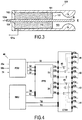
- solid propellant 100 is shown on the FIG 3 . It can be for example one of the small solid thrusters 11-14.
- the solid propellant 100 has a cylindrical body 101 and a base 102 closing a first end of the cylindrical body 101 and thus forming a cavity 103 inside the cylindrical body 101.
- a rod 104 passes through the base 102, enters the cavity 103 and extends substantially to the level of the second end of the cylindrical body 101.
- the cavity 103 is filled with a solid propellant 110.
- the cylindrical body 101 and the rod 104 are each formed of an electrically conductive material, not necessarily the same, while the base 102 is insulating.
- the cylindrical body 101 and the rod 104 thus constitute respectively a first and second electrode A and B, respectively connected to two terminals 101a and 104a.
- Solid propellant 110 is a solid propellant whose combustion is activated by an electric current or the presence of a field electric. It can be a monergol or a mixture of two or more chemical species.
- a voltage is applied between the electrodes A and B, the combustion of the solid propellant 110 is activated at its end surface 111 open on the outside and thus on the space E.
- the gases released during this combustion and ejected to the space E produce the thrust of the thruster 100.
- the adjustment of the voltage, current and / or polarity across the electrodes A and B affect the combustion and thus allow to modulate the thrust of the thruster 100
- the combustion stops and the thruster 100 thus turns off when the voltage across the electrodes A and B is canceled.
- the solid-state thrusters 10-14 and electrical thrusters 20-24 are powered and controlled by the shared power supply and control system 40.
- This comprises a PDU power distribution device, a PPU power supply and control device, and an ETSU switching device. It furthermore includes an on-board computer SMU. Its operation is best appreciated in the light of FIG 4 .
- the PDU power distribution device receives the electrical power from the solar panels 30a, 30b and the batteries 31, regulates it, and provides a regulated power supply, in the form of a power bus 32, for the other modules of the system. 40.
- This power bus 32 is regulated under 50V or 100V for example.
- the PPU and the ETSU might be able to accept unregulated voltage delivered directly from the solar panels or batteries and the PDU can be omitted.
- the power supply and control device PPU receives the electrical power from the power bus 32: it uses the latter that reconditions in different ways to provide several power supplies of different types together in several power interfaces 33, 34 It provides, in particular for each interface 33, 34, a main power supply 33a, 34a of high power and one or more auxiliary power supply (33b, 33c, 34b, 34c) of lower power.
- the main power supply 33a, 34a provides a modulable DC voltage of up to 1000 V with a power of several kW.
- Auxiliary power supplies 33b 33c, 34b, 34c here provide voltages of the order of 20 V to 350 V with a power of a few tens or a hundred W.
- Each interface 33, 34 thus comprises a plurality of supply channels 33a, 33b, 33c, respectively 34a, 34b, 34c (three are here represented for each thruster but there may be more) to feed a thruster 10-14 or 20-24 and control each of its functions.
- Each power supply 33a, 33b, 33c (respectively 34a, 34b, 34c) can be supplied in several copies at the output of the power supply and control device PPU, the latter being capable of controlling and modulating them individually. Additional power supplies of different types are naturally conceivable.
- the PPU typically incorporates a switching capability between two electric thrusters (output interfaces 33 and 34).
- the ETSU switching device makes it possible to drive more thrusters (here four) from the same PPU by splitting again the two power supply interfaces 33, 34 to the different thrusters 10-14 and 20-24. It receives as input the power supplies 33a-33c and 34a-34c of each interface 33, 34 and has at its output the electrical connection harnesses 41-44 of the thrusters 10-14, 20-24.
- Each harness 41-44 has a plurality of channels 41a-44c corresponding to the plurality of channels 33a-33c and 34a-34c of the power supply interfaces 33, 34.
- FIG 4 being primarily diagrammatic, the representation of the switching device ETSU has been greatly simplified to represent as input only three power supplies for each electric propulsion interface 33, 34 useful for the presentation and output that four electrical connection harnesses 41-44 despite a larger number of thrusters described so far.
- the ETSU switching device is powered by the power bus 32 and has a relay network 45 allowing the desired switching to direct the power and control of a given power interface 33, 34 to a thruster 10-14, 20 -24 to activate.
- a relay network 45 allowing the desired switching to direct the power and control of a given power interface 33, 34 to a thruster 10-14, 20 -24 to activate.
- all the channels 33a-33c of a given power interface 33 are switched to the channels 41a-41c of the same electrical connection harness 41 respecting their correspondences.
- the electrical connection harnesses 41 and 42 can feed two electric thrusters 20-24 while the connection harnesses 43 and 44 can feed two solid thrusters.
- the control device is then capable of connecting each power supply unit to the electric thrusters 20-24 via the connection interface 33 and the electrical connection harnesses 41 and 42 adapted for these thrusters, and capable of connecting this same set of connectors.
- solid-state power supplies 10-14 via the connection interface 34 and the connection harnesses 43 and 44 adapted for these other thrusters.
- the PPU-ETSU assembly may have an output adapted to a main electric thruster 20a or 20b, and four outputs adapted to the auxiliary thrusters 10-14 or 20-24.
- the second main electric thruster and the other four auxiliary thrusters are then powered by a second set of PPU-ETSU in order to have a better fault resistance.
- the on-board computer SMU exchanges data via telemetry TM / TC remote control with the power and control device PPU on the one hand and the switching device ETSU on the other hand.
- the latter sends them thrust instructions for given thrusters 10-14, 20-24.
- the PPU power and control device which integrates the thruster control logic, their telemetry and their remote control, modulates the power supplied by the power supplies concerned and transmits certain commands or adjustments for the thrusters concerned. -14, 20-24 via some of the channels 33a-34c of the power supply interfaces 33 or 34.
- the ETSU switching device then carries out the switching (s) necessary to connect the concerned power supplies to the thrusters 10-14, 20-24 concerned.
- the PPU power and control device further comprises an internal switching device that complements the external ETSU switching device and participates in the overall switching scheme.
- the device PPU can be simplified to have only one common motor supply interface 33, the external switching device ETSU assuring all the switching functions between the different thrusters to suitable interfaces.
Landscapes
- Engineering & Computer Science (AREA)
- Remote Sensing (AREA)
- Combustion & Propulsion (AREA)
- Chemical & Material Sciences (AREA)
- Aviation & Aerospace Engineering (AREA)
- Radar, Positioning & Navigation (AREA)
- Mechanical Engineering (AREA)
- General Engineering & Computer Science (AREA)
- Power Engineering (AREA)
- Automation & Control Theory (AREA)
- Physics & Mathematics (AREA)
- General Physics & Mathematics (AREA)
- Astronomy & Astrophysics (AREA)
- Control Of Position, Course, Altitude, Or Attitude Of Moving Bodies (AREA)
- Plasma & Fusion (AREA)
- Charge And Discharge Circuits For Batteries Or The Like (AREA)
Claims (11)
- Raumfahrzeug, umfassend
mindestens ein chemisches Feststoffantriebswerk (10 - 14) und mindestens ein elektrisches Antriebswerk (20 - 24), und
dadurch gekennzeichnet, dass es ferner ein gemeinsames Versorgungs- und Steuersystem (40) umfasst, das dazu ausgelegt ist, Strom zu liefern und das chemische Feststoffantriebswerk (10 - 14) einerseits und das elektrische Antriebswerk (20 - 24) andererseits zu steuern, wobei das gemeinsame Versorgungs- und Steuersystem (40) umfasst
eine Stromverteilungsvorrichtung (PDU), die dazu ausgelegt ist, eine geregelte Stromversorgung (32) von mindestens einer Stromquelle (30a, 30b, 31) bereitzustellen,
eine Versorgungs- und Steuerungseinheit (PPU), die dazu ausgelegt ist, eine Mehrzahl von Stromversorgungen (33a - 33c, 34a - 34c) verschiedener Typen von der geregelten Stromversorgung (32) aus bereitzustellen, und
eine Schaltvorrichtung (ETSU), die dazu ausgelegt ist, einige der Stromversorgungen (33a - 33c, 34a - 34c) selektiv mit einigen der Antriebswerke (10 - 14, 20 - 24) zu verbinden. - Raumfahrzeug gemäß Anspruch 1, dadurch gekennzeichnet, dass das chemische Feststoffantriebswerk (10-14) vom elektrisch steuerbaren Typ ist, um das Antriebswerk (10-14) ein- und auszuschalten und seinen Schub zu modulieren.
- Raumfahrzeug gemäß Anspruch 1 oder 2, dadurch gekennzeichnet, dass die Fernmessung, Fernsteuerung und Steuerlogik des chemischen Feststoffantriebswerks (10 - 14) und des elektrischen Antriebswerks (20 - 24) in der Versorgungs- und Steuerungseinheit (PPU) gemeinsam genutzt werden.
- Raumfahrzeug gemäß einem der Ansprüche 1 bis 3, dadurch gekennzeichnet, dass die Versorgungs- und Steuerungseinheit (PPU) mindestens eine Hauptstromversorgung (33a, 34a) für den Betrieb des elektrischen Antriebswerks (20-24) und mindestens eine Hilfsstromversorgung (33b, 33c, 34b, 34c) für den Betrieb des chemischen Feststoffantriebswerks (10-14) bereitstellt.
- Raumfahrzeug gemäß Anspruch 4, dadurch gekennzeichnet, dass die Hauptstromversorgung (33a, 34a) eine Gleichspannung zwischen etwa 200 V und 1500 V mit einer Leistung zwischen etwa 1 kW und 10 kW bereitstellt,
und dass die Hilfsstromversorgung (33b, 33c, 34b, 34c) eine Gleichspannung zwischen etwa 20 V und 350 V mit einer Leistung zwischen etwa 50 W und 200 W bereitstellt. - Raumfahrzeug gemäß einem der Ansprüche 1 bis 5, dadurch gekennzeichnet, dass die Versorgungs- und Steuerungseinheit (PPU) so ausgelegt ist, dass sie den gleichzeitigen Betrieb eines chemischen Feststoffantriebswerks (10 - 14) und eines elektrischen Antriebswerks (20 - 24) ermöglicht.
- Raumfahrzeug gemäß einem der Ansprüche 1 bis 6, dadurch gekennzeichnet, dass es mindestens ein chemisches Hauptfeststoffantriebswerk (10) und eine Mehrzahl von kleineren chemischen Feststoffantriebswerken (11 - 14) mit geringerer Leistung umfasst.
- Raumfahrzeug gemäß einem der Ansprüche 1 bis 7, dadurch gekennzeichnet, dass es mindestens ein elektrisches Hauptantriebswerk (20a, 20b) und eine Mehrzahl von kleineren elektrischen Antriebswerken (21 - 24) mit geringerer Leistung umfasst.
- Raumfahrzeug gemäß Anspruch 7 oder 8, dadurch gekennzeichnet, dass es umfasst:ein chemisches Hauptfeststoffantriebswerk (10), das im Wesentlichen auf einer Trägheitsachse des Fahrzeugs (1) angeordnet und entlang dieser ausgerichtet ist,eine Mehrzahl von elektrischen Hauptantriebswerken (20a, 20b), die um das chemische Hauptfeststoffantriebswerk (10) herum angeordnet sind, undmindestens drei kleinere chemische Feststoffantriebswerke (11 - 14) oder drei kleinere elektrische Antriebswerke (21 - 24), die in nicht koplanare Richtungen ausgerichtet sind.
- Raumfahrzeug gemäß einem der Ansprüche 1 bis 9, dadurch gekennzeichnet, dass sein Antrieb ausschließlich mittels chemischer Feststoffantriebswerke (10 - 14) und elektrischer Antriebswerke (20 - 24) erfolgt.
- Raumfahrzeug gemäß einem der Ansprüche 1 bis 10, dadurch gekennzeichnet, dass es ferner mindestens eine Schuborientierungsvorrichtung umfasst, mit der sich die Orientierung des Schubvektors eines Feststoffantriebswerks steuern lässt, und dass die Versorgungs- und Steuerungsvorrichtung (PPU) mindestens eine Stromversorgung für den Betrieb der mindestens einen Schuborientierungsvorrichtung bereitstellt.
Applications Claiming Priority (2)
| Application Number | Priority Date | Filing Date | Title |
|---|---|---|---|
| FR1250945A FR2986213B1 (fr) | 2012-02-01 | 2012-02-01 | Engin spatial a propulsion electrique et chimique a propergol solide |
| PCT/FR2013/050208 WO2013114049A1 (fr) | 2012-02-01 | 2013-01-31 | Engin spatial a propulsion electrique et chimique a propergol solide. |
Publications (2)
| Publication Number | Publication Date |
|---|---|
| EP2809582A1 EP2809582A1 (de) | 2014-12-10 |
| EP2809582B1 true EP2809582B1 (de) | 2018-10-24 |
Family
ID=47754801
Family Applications (1)
| Application Number | Title | Priority Date | Filing Date |
|---|---|---|---|
| EP13706610.6A Not-in-force EP2809582B1 (de) | 2012-02-01 | 2013-01-31 | Raumfahrzeug mit elektrischem und chemischem feststoffantrieb |
Country Status (4)
| Country | Link |
|---|---|
| US (1) | US10442558B2 (de) |
| EP (1) | EP2809582B1 (de) |
| FR (1) | FR2986213B1 (de) |
| WO (1) | WO2013114049A1 (de) |
Families Citing this family (28)
| Publication number | Priority date | Publication date | Assignee | Title |
|---|---|---|---|---|
| FR2986213B1 (fr) * | 2012-02-01 | 2014-10-10 | Snecma | Engin spatial a propulsion electrique et chimique a propergol solide |
| US20130327015A1 (en) * | 2012-06-12 | 2013-12-12 | Pamela Pollet | Dual use hydrazine propulsion thruster system |
| FR3002594B1 (fr) | 2013-02-26 | 2016-09-30 | Snecma | Module de propulsion spatiale a propulsion electrique et chimique a propergol solide |
| FR3021301B1 (fr) * | 2014-05-21 | 2017-12-29 | Snecma | Moteur pour engin spatial, et engin spatial comprenant un tel moteur |
| FR3024436B1 (fr) * | 2014-07-30 | 2018-01-05 | Safran Aircraft Engines | Systeme et procede de propulsion spatiale |
| CN104260901B (zh) * | 2014-09-11 | 2016-08-24 | 上海卫星工程研究所 | 模块化的双组元推进系统 |
| US10428806B2 (en) | 2016-01-22 | 2019-10-01 | The Boeing Company | Structural Propellant for ion rockets (SPIR) |
| DE102016110965B4 (de) | 2016-06-15 | 2019-03-14 | Helmholtz-Zentrum Berlin Für Materialien Und Energie Gmbh | Halbleiter-Bauelement mit vorder- und rückseitiger Elektrode und Verfahren zu dessen Herstellung |
| US10954005B1 (en) * | 2016-07-25 | 2021-03-23 | Space Systems/Loral, Llc | Power train for deep space solar electric propulsion |
| FR3065202B1 (fr) * | 2017-04-18 | 2020-07-17 | Centre National D'etudes Spatiales | Propulseur spatial |
| WO2019195782A1 (en) | 2018-04-05 | 2019-10-10 | Michigan Technological University | On-board propulsion testing apparatus |
| US11203447B1 (en) * | 2018-05-14 | 2021-12-21 | United States Of America As Represented By The Secretary Of The Air Force | Propulsion system for space vehicles |
| EP3620394A1 (de) * | 2018-09-06 | 2020-03-11 | Airbus Defence and Space Limited | Antriebssystem |
| US11346306B1 (en) | 2019-01-03 | 2022-05-31 | Ball Aerospace & Technologies Corp. | Chemical and cold gas propellant systems and methods |
| US11498705B1 (en) | 2019-05-09 | 2022-11-15 | Ball Aerospace & Technology Corp. | On orbit fluid propellant dispensing systems and methods |
| IT201900012498A1 (it) * | 2019-07-22 | 2021-01-22 | D Orbit S P A | Modulo satellitare per la determinazione di assetto |
| CN113767220B (zh) | 2020-04-02 | 2024-11-29 | 奥比恩空间技术公司 | 霍尔效应推力器 |
| WO2021225620A1 (en) * | 2020-05-08 | 2021-11-11 | Orbion Space Technology, Inc. | Propulsion system for spacecraft |
| CN111891393B (zh) * | 2020-08-11 | 2022-03-15 | 中国科学院微小卫星创新研究院 | 小型高轨卫星公用平台的混合推进舱 |
| CN114313309B (zh) * | 2020-08-12 | 2023-08-04 | 中国科学院微小卫星创新研究院 | 小型高轨卫星的自主变轨方法 |
| CN112160849A (zh) * | 2020-09-30 | 2021-01-01 | 内蒙动力机械研究所 | 一种用于电控固体火箭发动机的电极装置 |
| US12012233B2 (en) | 2021-05-10 | 2024-06-18 | Ball Aerospace & Technologies Corp. | Active on orbit fluid propellant management and refueling systems and methods |
| FR3122861A1 (fr) * | 2021-05-12 | 2022-11-18 | Centre National d'Études Spatiales | Engin spatial de distribution électrique, et procédé associé |
| US11945606B1 (en) | 2021-10-19 | 2024-04-02 | Ball Aerospace & Technologies Corp. | Electric propulsion based spacecraft propulsion systems and methods utilizing multiple propellants |
| CN115142983B (zh) * | 2022-06-16 | 2024-08-27 | 中国人民解放军战略支援部队航天工程大学 | 一种基于化-电深度融合的航天器混合动力推力器 |
| DE102022130071A1 (de) * | 2022-11-14 | 2024-05-16 | Gate Space Innovation Gmbh | Auf dem Rückstoßprinzip basierende Antriebseinheit für eine Nutzlast im Weltall |
| WO2025041118A1 (en) * | 2023-08-21 | 2025-02-27 | Saguirel Michael | Rotational drive |
| CN118479062B (zh) * | 2024-05-20 | 2024-12-24 | 中国人民解放军战略支援部队航天工程大学 | 区域协同式两相混合空间推进系统及推进方法 |
Family Cites Families (52)
| Publication number | Priority date | Publication date | Assignee | Title |
|---|---|---|---|---|
| US4069664A (en) * | 1974-01-24 | 1978-01-24 | Hughes Aircraft Company | Monopropellant thruster |
| FR2669887B1 (fr) * | 1990-11-30 | 1995-06-02 | Aerospatiale | Procede de controle d'attitude en tangage d'un satellite grace a la pression de radiation solaire et satellite adapte a sa mise en óoeuvre. |
| US5170623A (en) * | 1991-01-28 | 1992-12-15 | Trw Inc. | Hybrid chemical/electromagnetic propulsion system |
| US5651515A (en) * | 1995-01-30 | 1997-07-29 | Agence Spatiale Europeenne | Method for re-orbiting a dual-mode propulsion geostationary spacecraft |
| US5711348A (en) * | 1996-08-14 | 1998-01-27 | Moog Inc. | Hot gas control valve |
| US6032904A (en) * | 1998-02-23 | 2000-03-07 | Space Systems/Loral, Inc. | Multiple usage thruster mounting configuration |
| US6269629B1 (en) * | 1998-08-17 | 2001-08-07 | The United States Of America As Represented By The Secretary Of The Air Force | Micro-pulsed plasma thruster having coaxial cable segment propellant modules |
| US6216445B1 (en) * | 1999-05-19 | 2001-04-17 | Trw Inc. | Micro pulsed plasma thruster and method of operating same |
| US7113851B1 (en) * | 1999-06-09 | 2006-09-26 | Walter Gelon | Practical orbit raising system and method for geosynchronous satellites |
| US6445981B1 (en) * | 2000-03-02 | 2002-09-03 | Space Systems/Loral, Inc. | Controller and control method for satellite orbit-keeping maneuvers |
| US6439507B1 (en) * | 2000-05-05 | 2002-08-27 | Space Systems/Loral, Inc. | Closed-loop spacecraft orbit control |
| US6464174B1 (en) * | 2000-06-21 | 2002-10-15 | Space Systems/Loral, Inc. | Round-trip orbital operation of a spacecraft |
| US6481672B1 (en) * | 2001-01-18 | 2002-11-19 | Lockheed Martin Corporation | Gimbaled thruster control system |
| US6541916B2 (en) * | 2001-01-30 | 2003-04-01 | Trw Inc. | Method for providing discharge power to electric propulsion thrusters |
| US6543723B1 (en) * | 2001-09-04 | 2003-04-08 | Space Systems/Loral, Inc. | Electric orbit raising with variable thrust |
| US6581880B2 (en) * | 2001-10-15 | 2003-06-24 | Space Systems/Loral, Inc. | Energy managed electric propulsion methods and systems for stationkeeping satellites |
| US6565043B1 (en) * | 2001-12-21 | 2003-05-20 | The Boeing Company | Redundant system for satellite inclination control with electric thrusters |
| US6732977B1 (en) * | 2002-02-11 | 2004-05-11 | Lockheed Martin Corporation | System for on-orbit correction of spacecraft payload pointing errors |
| US6695263B1 (en) * | 2002-02-12 | 2004-02-24 | Lockheed Martin Corporation | System for geosynchronous spacecraft rapid earth reacquisition |
| US7051980B2 (en) * | 2002-02-26 | 2006-05-30 | Lockheed Martin Corporation | Efficient orbit sparing system for space vehicle constellations |
| US6702234B1 (en) * | 2002-03-29 | 2004-03-09 | Lockheed Martin Corporation | Fault tolerant attitude control system for zero momentum spacecraft |
| US6637701B1 (en) * | 2002-04-03 | 2003-10-28 | Lockheed Martin Corporation | Gimbaled ion thruster arrangement for high efficiency stationkeeping |
| US7530219B1 (en) * | 2002-06-14 | 2009-05-12 | Cu Aerospace, Llc | Advanced pulsed plasma thruster with high electromagnetic thrust |
| AU2003304728A1 (en) * | 2002-11-01 | 2009-05-28 | W.E. Research, Llc | Dual-mode chemical-electric thrusters for spacecraft |
| US7149611B2 (en) * | 2003-02-21 | 2006-12-12 | Lockheed Martin Corporation | Virtual sensor mast |
| US7059571B2 (en) * | 2003-02-21 | 2006-06-13 | The Boeing Company | Deployable spacecraft mount for electric propulsion |
| US7118075B2 (en) * | 2003-06-13 | 2006-10-10 | Schubert Peter J | System and method for attitude control and station keeping |
| WO2005003557A1 (en) * | 2003-06-25 | 2005-01-13 | Design Net Engineering, Llc | Laser propulsion thruster |
| US6948305B2 (en) * | 2003-07-09 | 2005-09-27 | The Boeing Company | Method and apparatus for balancing the emission current of neutralizers in ion thruster arrays |
| US6945500B2 (en) * | 2003-08-15 | 2005-09-20 | Skycorp, Inc. | Apparatus for a geosynchronous life extension spacecraft |
| WO2005037646A2 (en) * | 2003-10-14 | 2005-04-28 | Lockheed Martin Corporation | Precision attitude control system for gimbaled thruster |
| US7665695B2 (en) * | 2003-12-03 | 2010-02-23 | The Boeing Company | Unified attitude control for spacecraft transfer orbit operations |
| US6996972B2 (en) * | 2004-05-18 | 2006-02-14 | The Boeing Company | Method of ionizing a liquid propellant and an electric thruster implementing such a method |
| US7530218B2 (en) * | 2004-07-14 | 2009-05-12 | The Johns Hopkins University | Pulsed plasma thruster using vapor |
| US7958823B2 (en) * | 2004-12-17 | 2011-06-14 | Sawka Wayne N | Controllable digital solid state cluster thrusters for rocket propulsion and gas generation |
| US7872848B2 (en) * | 2005-08-11 | 2011-01-18 | The Boeing Company | Method of ionizing a liquid and an electrostatic colloid thruster implementing such a method |
| US9101898B2 (en) * | 2006-03-29 | 2015-08-11 | Robert M. Zubrin | Portable gas generating device |
| US7736751B2 (en) * | 2006-09-20 | 2010-06-15 | The Boeing Company | Coating for components requiring hydrogen peroxide compatibility |
| US7690187B2 (en) * | 2006-09-26 | 2010-04-06 | The Aerospace Corporation | Modular micropropulsion device and system |
| DE102007006444B4 (de) * | 2007-02-05 | 2015-05-13 | Airbus Defence and Space GmbH | Mikrotriebwerk, insbesondere zur Verwendung als Lageregelungstriebwerk, Kleintriebwerk sowie Verfahren zum Herstellen eines Mikrotriebwerks |
| US8016240B2 (en) * | 2007-03-29 | 2011-09-13 | The Boeing Company | Satellites and satellite fleet implementation methods and apparatus |
| US8236441B2 (en) * | 2007-07-24 | 2012-08-07 | A123 Systems, Inc. | Battery cell design and methods of its construction |
| US8613188B2 (en) * | 2008-05-14 | 2013-12-24 | Purdue Research Foundation | Method of enhancing microthruster performance |
| US8857338B2 (en) * | 2008-05-16 | 2014-10-14 | Digital Solid State Propulsion Llc | Electrode ignition and control of electrically ignitable materials |
| US8550405B2 (en) * | 2009-09-29 | 2013-10-08 | Busek Company, Inc. | Solar powered spacecraft power system for a hall effect thruster |
| US9145216B2 (en) * | 2011-08-31 | 2015-09-29 | Space Systems/Loral, Llc | Unified chemical electric propulsion system |
| FR2986213B1 (fr) * | 2012-02-01 | 2014-10-10 | Snecma | Engin spatial a propulsion electrique et chimique a propergol solide |
| US8763957B1 (en) * | 2012-10-08 | 2014-07-01 | Space Systems/Loral, Llc | Spacecraft transfer orbit techniques |
| US8998146B2 (en) * | 2012-11-21 | 2015-04-07 | Space Systems/Loral, Llc | Spacecraft momentum unload and station-keeping techniques |
| US10183765B2 (en) * | 2014-03-12 | 2019-01-22 | Lockheed Martin Corporation | Thruster arrangement for geosynchronous orbit spacecraft |
| FR3022530B1 (fr) * | 2014-06-19 | 2018-03-02 | Airbus Defence And Space Sas | Procede de controle d'orbite d'un satellite en orbite terrestre, satellite et systeme de controle d'orbite d'un tel satellite |
| US10336475B1 (en) * | 2015-11-10 | 2019-07-02 | Space Systems/Loral, Llc | Flexible propulsion system |
-
2012
- 2012-02-01 FR FR1250945A patent/FR2986213B1/fr active Active
-
2013
- 2013-01-31 WO PCT/FR2013/050208 patent/WO2013114049A1/fr not_active Ceased
- 2013-01-31 US US14/375,615 patent/US10442558B2/en active Active
- 2013-01-31 EP EP13706610.6A patent/EP2809582B1/de not_active Not-in-force
Non-Patent Citations (1)
| Title |
|---|
| None * |
Also Published As
| Publication number | Publication date |
|---|---|
| US10442558B2 (en) | 2019-10-15 |
| US20150021439A1 (en) | 2015-01-22 |
| EP2809582A1 (de) | 2014-12-10 |
| FR2986213A1 (fr) | 2013-08-02 |
| WO2013114049A1 (fr) | 2013-08-08 |
| FR2986213B1 (fr) | 2014-10-10 |
Similar Documents
| Publication | Publication Date | Title |
|---|---|---|
| EP2809582B1 (de) | Raumfahrzeug mit elektrischem und chemischem feststoffantrieb | |
| EP3201090B1 (de) | Satellit mit elektrischer antriebsvorrichtung, verfahren zur platzierung solch eines satelliten in einer station und verfahren zum halten des besagten satelliten in seiner station | |
| EP3083406B1 (de) | Verfahren und system zur übertragung eines satelliten aus einer ersten umlaufbahn in eine missionsumlaufbahn | |
| EP2666723B1 (de) | Antriebssystem für die Kontrolle der Umlaufbahn und der Lage von Satelliten | |
| EP2961656B1 (de) | Weltraumantriebsmodul mit elektrischem und chemischem feststoffantrieb | |
| EP2810875B1 (de) | Bimodulares Antriebssystem für Orbit- und Fluglageregelung eines Satelliten | |
| EP2660154B1 (de) | Antriebssystem für die Kontrolle der Umlaufbahn und der Lageregelung eines Satelliten | |
| EP2810876B1 (de) | Viermodulares Antriebssystem für Orbit- und Fluglageregelung eines Satelliten | |
| EP2690020A2 (de) | Verfahren zur Reduzierung des Drehimpulses und zur Fluglageregelung eines Raumfahrzeugs | |
| EP2878539B1 (de) | Düsensystem und verfahren zur kontrolle der umlaufbahn und des verhaltens für geostationären satelliten | |
| WO1992009479A2 (fr) | Procede de controle d'attitude en tangage d'un satellite grace a la pression de radiation solaire et satellite adapte a sa mise en ×uvre | |
| CA2964672A1 (fr) | Systeme propulsif hybride d'un aeronef multi-moteur | |
| FR2975481A1 (fr) | Systeme pour le pilotage en force et le controle d'attitude en vol d'un vehicule et engin comportant un tel systeme | |
| EP0047211B1 (de) | Verfahren zum Verändern der Umlaufbahn eines Satelliten, insbesondere zur Injektion in eine geostationäre Umlaufbahn, und für dieses Verfahren geeigneter Satellit | |
| FR3024709A1 (fr) | Procede et systeme pour le transfert d'un satellite d'une orbite initiale dans une orbite de mission | |
| FR3115769A1 (fr) | Vaisseau spatial équipé de propulseur à antimatière. | |
| FR2761339A1 (fr) | Appareil et procede de commande d'attitude pour engin spatial utilisant un sous-systeme d'alimentation electrique | |
| EP4337536B1 (de) | Raumfahrzeug zur stromverteilung und zugehöriges verfahren | |
| FR3131907A1 (fr) | Module de déploiement orbital avec un système de propulsion spatial à trois points |
Legal Events
| Date | Code | Title | Description |
|---|---|---|---|
| PUAI | Public reference made under article 153(3) epc to a published international application that has entered the european phase |
Free format text: ORIGINAL CODE: 0009012 |
|
| 17P | Request for examination filed |
Effective date: 20140828 |
|
| AK | Designated contracting states |
Kind code of ref document: A1 Designated state(s): AL AT BE BG CH CY CZ DE DK EE ES FI FR GB GR HR HU IE IS IT LI LT LU LV MC MK MT NL NO PL PT RO RS SE SI SK SM TR |
|
| AX | Request for extension of the european patent |
Extension state: BA ME |
|
| RBV | Designated contracting states (corrected) |
Designated state(s): AL AT BE BG CH CY CZ DE DK EE ES FI GB GR HR HU IE IS IT LI LT LU LV MC MK MT NL NO PL PT RO RS SE SI SK SM TR |
|
| DAX | Request for extension of the european patent (deleted) | ||
| RAP1 | Party data changed (applicant data changed or rights of an application transferred) |
Owner name: SAFRAN CERAMICS |
|
| GRAP | Despatch of communication of intention to grant a patent |
Free format text: ORIGINAL CODE: EPIDOSNIGR1 |
|
| RIC1 | Information provided on ipc code assigned before grant |
Ipc: F02K 9/22 20060101ALI20180710BHEP Ipc: B64G 1/40 20060101AFI20180710BHEP Ipc: B64G 1/24 20060101ALI20180710BHEP Ipc: B64G 1/42 20060101ALI20180710BHEP |
|
| STAA | Information on the status of an ep patent application or granted ep patent |
Free format text: STATUS: GRANT OF PATENT IS INTENDED |
|
| INTG | Intention to grant announced |
Effective date: 20180816 |
|
| RIN1 | Information on inventor provided before grant (corrected) |
Inventor name: YVART, PIERRE, MARCEL Inventor name: DUCHEMIN, OLIVIER |
|
| GRAS | Grant fee paid |
Free format text: ORIGINAL CODE: EPIDOSNIGR3 |
|
| GRAA | (expected) grant |
Free format text: ORIGINAL CODE: 0009210 |
|
| STAA | Information on the status of an ep patent application or granted ep patent |
Free format text: STATUS: THE PATENT HAS BEEN GRANTED |
|
| AK | Designated contracting states |
Kind code of ref document: B1 Designated state(s): AL AT BE BG CH CY CZ DE DK EE ES FI GB GR HR HU IE IS IT LI LT LU LV MC MK MT NL NO PL PT RO RS SE SI SK SM TR |
|
| REG | Reference to a national code |
Ref country code: CH Ref legal event code: EP |
|
| REG | Reference to a national code |
Ref country code: IE Ref legal event code: FG4D Free format text: LANGUAGE OF EP DOCUMENT: FRENCH |
|
| REG | Reference to a national code |
Ref country code: AT Ref legal event code: REF Ref document number: 1056383 Country of ref document: AT Kind code of ref document: T Effective date: 20181115 |
|
| REG | Reference to a national code |
Ref country code: DE Ref legal event code: R096 Ref document number: 602013045501 Country of ref document: DE |
|
| REG | Reference to a national code |
Ref country code: SE Ref legal event code: TRGR |
|
| REG | Reference to a national code |
Ref country code: NL Ref legal event code: MP Effective date: 20181024 |
|
| REG | Reference to a national code |
Ref country code: LT Ref legal event code: MG4D |
|
| REG | Reference to a national code |
Ref country code: AT Ref legal event code: MK05 Ref document number: 1056383 Country of ref document: AT Kind code of ref document: T Effective date: 20181024 |
|
| PG25 | Lapsed in a contracting state [announced via postgrant information from national office to epo] |
Ref country code: NL Free format text: LAPSE BECAUSE OF FAILURE TO SUBMIT A TRANSLATION OF THE DESCRIPTION OR TO PAY THE FEE WITHIN THE PRESCRIBED TIME-LIMIT Effective date: 20181024 |
|
| PG25 | Lapsed in a contracting state [announced via postgrant information from national office to epo] |
Ref country code: BG Free format text: LAPSE BECAUSE OF FAILURE TO SUBMIT A TRANSLATION OF THE DESCRIPTION OR TO PAY THE FEE WITHIN THE PRESCRIBED TIME-LIMIT Effective date: 20190124 Ref country code: NO Free format text: LAPSE BECAUSE OF FAILURE TO SUBMIT A TRANSLATION OF THE DESCRIPTION OR TO PAY THE FEE WITHIN THE PRESCRIBED TIME-LIMIT Effective date: 20190124 Ref country code: PL Free format text: LAPSE BECAUSE OF FAILURE TO SUBMIT A TRANSLATION OF THE DESCRIPTION OR TO PAY THE FEE WITHIN THE PRESCRIBED TIME-LIMIT Effective date: 20181024 Ref country code: HR Free format text: LAPSE BECAUSE OF FAILURE TO SUBMIT A TRANSLATION OF THE DESCRIPTION OR TO PAY THE FEE WITHIN THE PRESCRIBED TIME-LIMIT Effective date: 20181024 Ref country code: LV Free format text: LAPSE BECAUSE OF FAILURE TO SUBMIT A TRANSLATION OF THE DESCRIPTION OR TO PAY THE FEE WITHIN THE PRESCRIBED TIME-LIMIT Effective date: 20181024 Ref country code: FI Free format text: LAPSE BECAUSE OF FAILURE TO SUBMIT A TRANSLATION OF THE DESCRIPTION OR TO PAY THE FEE WITHIN THE PRESCRIBED TIME-LIMIT Effective date: 20181024 Ref country code: AT Free format text: LAPSE BECAUSE OF FAILURE TO SUBMIT A TRANSLATION OF THE DESCRIPTION OR TO PAY THE FEE WITHIN THE PRESCRIBED TIME-LIMIT Effective date: 20181024 Ref country code: IS Free format text: LAPSE BECAUSE OF FAILURE TO SUBMIT A TRANSLATION OF THE DESCRIPTION OR TO PAY THE FEE WITHIN THE PRESCRIBED TIME-LIMIT Effective date: 20190224 Ref country code: ES Free format text: LAPSE BECAUSE OF FAILURE TO SUBMIT A TRANSLATION OF THE DESCRIPTION OR TO PAY THE FEE WITHIN THE PRESCRIBED TIME-LIMIT Effective date: 20181024 Ref country code: LT Free format text: LAPSE BECAUSE OF FAILURE TO SUBMIT A TRANSLATION OF THE DESCRIPTION OR TO PAY THE FEE WITHIN THE PRESCRIBED TIME-LIMIT Effective date: 20181024 |
|
| PG25 | Lapsed in a contracting state [announced via postgrant information from national office to epo] |
Ref country code: GR Free format text: LAPSE BECAUSE OF FAILURE TO SUBMIT A TRANSLATION OF THE DESCRIPTION OR TO PAY THE FEE WITHIN THE PRESCRIBED TIME-LIMIT Effective date: 20190125 Ref country code: PT Free format text: LAPSE BECAUSE OF FAILURE TO SUBMIT A TRANSLATION OF THE DESCRIPTION OR TO PAY THE FEE WITHIN THE PRESCRIBED TIME-LIMIT Effective date: 20190224 Ref country code: RS Free format text: LAPSE BECAUSE OF FAILURE TO SUBMIT A TRANSLATION OF THE DESCRIPTION OR TO PAY THE FEE WITHIN THE PRESCRIBED TIME-LIMIT Effective date: 20181024 Ref country code: AL Free format text: LAPSE BECAUSE OF FAILURE TO SUBMIT A TRANSLATION OF THE DESCRIPTION OR TO PAY THE FEE WITHIN THE PRESCRIBED TIME-LIMIT Effective date: 20181024 |
|
| REG | Reference to a national code |
Ref country code: DE Ref legal event code: R097 Ref document number: 602013045501 Country of ref document: DE |
|
| PG25 | Lapsed in a contracting state [announced via postgrant information from national office to epo] |
Ref country code: CZ Free format text: LAPSE BECAUSE OF FAILURE TO SUBMIT A TRANSLATION OF THE DESCRIPTION OR TO PAY THE FEE WITHIN THE PRESCRIBED TIME-LIMIT Effective date: 20181024 Ref country code: DK Free format text: LAPSE BECAUSE OF FAILURE TO SUBMIT A TRANSLATION OF THE DESCRIPTION OR TO PAY THE FEE WITHIN THE PRESCRIBED TIME-LIMIT Effective date: 20181024 |
|
| PG25 | Lapsed in a contracting state [announced via postgrant information from national office to epo] |
Ref country code: MC Free format text: LAPSE BECAUSE OF FAILURE TO SUBMIT A TRANSLATION OF THE DESCRIPTION OR TO PAY THE FEE WITHIN THE PRESCRIBED TIME-LIMIT Effective date: 20181024 Ref country code: SK Free format text: LAPSE BECAUSE OF FAILURE TO SUBMIT A TRANSLATION OF THE DESCRIPTION OR TO PAY THE FEE WITHIN THE PRESCRIBED TIME-LIMIT Effective date: 20181024 Ref country code: SM Free format text: LAPSE BECAUSE OF FAILURE TO SUBMIT A TRANSLATION OF THE DESCRIPTION OR TO PAY THE FEE WITHIN THE PRESCRIBED TIME-LIMIT Effective date: 20181024 Ref country code: EE Free format text: LAPSE BECAUSE OF FAILURE TO SUBMIT A TRANSLATION OF THE DESCRIPTION OR TO PAY THE FEE WITHIN THE PRESCRIBED TIME-LIMIT Effective date: 20181024 Ref country code: RO Free format text: LAPSE BECAUSE OF FAILURE TO SUBMIT A TRANSLATION OF THE DESCRIPTION OR TO PAY THE FEE WITHIN THE PRESCRIBED TIME-LIMIT Effective date: 20181024 |
|
| PLBE | No opposition filed within time limit |
Free format text: ORIGINAL CODE: 0009261 |
|
| REG | Reference to a national code |
Ref country code: CH Ref legal event code: PL |
|
| STAA | Information on the status of an ep patent application or granted ep patent |
Free format text: STATUS: NO OPPOSITION FILED WITHIN TIME LIMIT |
|
| PG25 | Lapsed in a contracting state [announced via postgrant information from national office to epo] |
Ref country code: LU Free format text: LAPSE BECAUSE OF NON-PAYMENT OF DUE FEES Effective date: 20190131 |
|
| 26N | No opposition filed |
Effective date: 20190725 |
|
| REG | Reference to a national code |
Ref country code: BE Ref legal event code: MM Effective date: 20190131 |
|
| REG | Reference to a national code |
Ref country code: IE Ref legal event code: MM4A |
|
| PG25 | Lapsed in a contracting state [announced via postgrant information from national office to epo] |
Ref country code: SI Free format text: LAPSE BECAUSE OF FAILURE TO SUBMIT A TRANSLATION OF THE DESCRIPTION OR TO PAY THE FEE WITHIN THE PRESCRIBED TIME-LIMIT Effective date: 20181024 |
|
| PG25 | Lapsed in a contracting state [announced via postgrant information from national office to epo] |
Ref country code: BE Free format text: LAPSE BECAUSE OF NON-PAYMENT OF DUE FEES Effective date: 20190131 |
|
| PG25 | Lapsed in a contracting state [announced via postgrant information from national office to epo] |
Ref country code: CH Free format text: LAPSE BECAUSE OF NON-PAYMENT OF DUE FEES Effective date: 20190131 Ref country code: LI Free format text: LAPSE BECAUSE OF NON-PAYMENT OF DUE FEES Effective date: 20190131 |
|
| PG25 | Lapsed in a contracting state [announced via postgrant information from national office to epo] |
Ref country code: IE Free format text: LAPSE BECAUSE OF NON-PAYMENT OF DUE FEES Effective date: 20190131 |
|
| PG25 | Lapsed in a contracting state [announced via postgrant information from national office to epo] |
Ref country code: TR Free format text: LAPSE BECAUSE OF FAILURE TO SUBMIT A TRANSLATION OF THE DESCRIPTION OR TO PAY THE FEE WITHIN THE PRESCRIBED TIME-LIMIT Effective date: 20181024 |
|
| PG25 | Lapsed in a contracting state [announced via postgrant information from national office to epo] |
Ref country code: MT Free format text: LAPSE BECAUSE OF FAILURE TO SUBMIT A TRANSLATION OF THE DESCRIPTION OR TO PAY THE FEE WITHIN THE PRESCRIBED TIME-LIMIT Effective date: 20181024 |
|
| PG25 | Lapsed in a contracting state [announced via postgrant information from national office to epo] |
Ref country code: CY Free format text: LAPSE BECAUSE OF FAILURE TO SUBMIT A TRANSLATION OF THE DESCRIPTION OR TO PAY THE FEE WITHIN THE PRESCRIBED TIME-LIMIT Effective date: 20181024 |
|
| PG25 | Lapsed in a contracting state [announced via postgrant information from national office to epo] |
Ref country code: HU Free format text: LAPSE BECAUSE OF FAILURE TO SUBMIT A TRANSLATION OF THE DESCRIPTION OR TO PAY THE FEE WITHIN THE PRESCRIBED TIME-LIMIT; INVALID AB INITIO Effective date: 20130131 |
|
| PG25 | Lapsed in a contracting state [announced via postgrant information from national office to epo] |
Ref country code: MK Free format text: LAPSE BECAUSE OF FAILURE TO SUBMIT A TRANSLATION OF THE DESCRIPTION OR TO PAY THE FEE WITHIN THE PRESCRIBED TIME-LIMIT Effective date: 20181024 |
|
| PGFP | Annual fee paid to national office [announced via postgrant information from national office to epo] |
Ref country code: SE Payment date: 20221222 Year of fee payment: 11 Ref country code: GB Payment date: 20221221 Year of fee payment: 11 |
|
| PGFP | Annual fee paid to national office [announced via postgrant information from national office to epo] |
Ref country code: IT Payment date: 20230103 Year of fee payment: 11 Ref country code: DE Payment date: 20221220 Year of fee payment: 11 |
|
| REG | Reference to a national code |
Ref country code: DE Ref legal event code: R119 Ref document number: 602013045501 Country of ref document: DE |
|
| GBPC | Gb: european patent ceased through non-payment of renewal fee |
Effective date: 20240131 |
|
| REG | Reference to a national code |
Ref country code: SE Ref legal event code: EUG |
|
| PG25 | Lapsed in a contracting state [announced via postgrant information from national office to epo] |
Ref country code: DE Free format text: LAPSE BECAUSE OF NON-PAYMENT OF DUE FEES Effective date: 20240801 |
|
| PG25 | Lapsed in a contracting state [announced via postgrant information from national office to epo] |
Ref country code: GB Free format text: LAPSE BECAUSE OF NON-PAYMENT OF DUE FEES Effective date: 20240131 |
|
| PG25 | Lapsed in a contracting state [announced via postgrant information from national office to epo] |
Ref country code: GB Free format text: LAPSE BECAUSE OF NON-PAYMENT OF DUE FEES Effective date: 20240131 Ref country code: DE Free format text: LAPSE BECAUSE OF NON-PAYMENT OF DUE FEES Effective date: 20240801 |
|
| PG25 | Lapsed in a contracting state [announced via postgrant information from national office to epo] |
Ref country code: IT Free format text: LAPSE BECAUSE OF NON-PAYMENT OF DUE FEES Effective date: 20240131 |
|
| PG25 | Lapsed in a contracting state [announced via postgrant information from national office to epo] |
Ref country code: SE Free format text: LAPSE BECAUSE OF NON-PAYMENT OF DUE FEES Effective date: 20240201 |