EP2811192B1 - Ensemble de roues pivotantes pour fauteuil roulant - Google Patents
Ensemble de roues pivotantes pour fauteuil roulant Download PDFInfo
- Publication number
- EP2811192B1 EP2811192B1 EP14170070.8A EP14170070A EP2811192B1 EP 2811192 B1 EP2811192 B1 EP 2811192B1 EP 14170070 A EP14170070 A EP 14170070A EP 2811192 B1 EP2811192 B1 EP 2811192B1
- Authority
- EP
- European Patent Office
- Prior art keywords
- bearing
- axis
- rotation
- caster wheel
- caster
- Prior art date
- Legal status (The legal status is an assumption and is not a legal conclusion. Google has not performed a legal analysis and makes no representation as to the accuracy of the status listed.)
- Active
Links
Images

Classifications
-
- A—HUMAN NECESSITIES
- A61—MEDICAL OR VETERINARY SCIENCE; HYGIENE
- A61G—TRANSPORT, PERSONAL CONVEYANCES, OR ACCOMMODATION SPECIALLY ADAPTED FOR PATIENTS OR DISABLED PERSONS; OPERATING TABLES OR CHAIRS; CHAIRS FOR DENTISTRY; FUNERAL DEVICES
- A61G5/00—Chairs or personal conveyances specially adapted for patients or disabled persons, e.g. wheelchairs
- A61G5/10—Parts, details or accessories
-
- A—HUMAN NECESSITIES
- A61—MEDICAL OR VETERINARY SCIENCE; HYGIENE
- A61G—TRANSPORT, PERSONAL CONVEYANCES, OR ACCOMMODATION SPECIALLY ADAPTED FOR PATIENTS OR DISABLED PERSONS; OPERATING TABLES OR CHAIRS; CHAIRS FOR DENTISTRY; FUNERAL DEVICES
- A61G5/00—Chairs or personal conveyances specially adapted for patients or disabled persons, e.g. wheelchairs
- A61G5/10—Parts, details or accessories
- A61G5/1051—Arrangements for steering
-
- B—PERFORMING OPERATIONS; TRANSPORTING
- B60—VEHICLES IN GENERAL
- B60B—VEHICLE WHEELS; CASTORS; AXLES FOR WHEELS OR CASTORS; INCREASING WHEEL ADHESION
- B60B33/00—Castors in general ; Anti-clogging castors
- B60B33/0028—Construction of wheels; methods of assembling on axle
-
- B—PERFORMING OPERATIONS; TRANSPORTING
- B60—VEHICLES IN GENERAL
- B60B—VEHICLE WHEELS; CASTORS; AXLES FOR WHEELS OR CASTORS; INCREASING WHEEL ADHESION
- B60B33/00—Castors in general ; Anti-clogging castors
- B60B33/04—Castors in general ; Anti-clogging castors adjustable, e.g. in height; linearly shifting castors
-
- B—PERFORMING OPERATIONS; TRANSPORTING
- B60—VEHICLES IN GENERAL
- B60B—VEHICLE WHEELS; CASTORS; AXLES FOR WHEELS OR CASTORS; INCREASING WHEEL ADHESION
- B60B2900/00—Purpose of invention
- B60B2900/10—Reduction of
- B60B2900/131—Vibrations
-
- B—PERFORMING OPERATIONS; TRANSPORTING
- B60—VEHICLES IN GENERAL
- B60B—VEHICLE WHEELS; CASTORS; AXLES FOR WHEELS OR CASTORS; INCREASING WHEEL ADHESION
- B60B33/00—Castors in general ; Anti-clogging castors
- B60B33/0036—Castors in general ; Anti-clogging castors characterised by type of wheels
- B60B33/0039—Single wheels
-
- B—PERFORMING OPERATIONS; TRANSPORTING
- B60—VEHICLES IN GENERAL
- B60B—VEHICLE WHEELS; CASTORS; AXLES FOR WHEELS OR CASTORS; INCREASING WHEEL ADHESION
- B60B33/00—Castors in general ; Anti-clogging castors
- B60B33/0047—Castors in general ; Anti-clogging castors characterised by details of the rolling axle
- B60B33/0049—Castors in general ; Anti-clogging castors characterised by details of the rolling axle the rolling axle being horizontal
-
- B—PERFORMING OPERATIONS; TRANSPORTING
- B60—VEHICLES IN GENERAL
- B60B—VEHICLE WHEELS; CASTORS; AXLES FOR WHEELS OR CASTORS; INCREASING WHEEL ADHESION
- B60B33/00—Castors in general ; Anti-clogging castors
- B60B33/0047—Castors in general ; Anti-clogging castors characterised by details of the rolling axle
- B60B33/0057—Castors in general ; Anti-clogging castors characterised by details of the rolling axle the rolling axle being offset from swivel axis
-
- B—PERFORMING OPERATIONS; TRANSPORTING
- B60—VEHICLES IN GENERAL
- B60B—VEHICLE WHEELS; CASTORS; AXLES FOR WHEELS OR CASTORS; INCREASING WHEEL ADHESION
- B60B33/00—Castors in general ; Anti-clogging castors
- B60B33/006—Castors in general ; Anti-clogging castors characterised by details of the swivel mechanism
- B60B33/0065—Castors in general ; Anti-clogging castors characterised by details of the swivel mechanism characterised by details of the swivel axis
- B60B33/0068—Castors in general ; Anti-clogging castors characterised by details of the swivel mechanism characterised by details of the swivel axis the swivel axis being vertical
-
- B—PERFORMING OPERATIONS; TRANSPORTING
- B60—VEHICLES IN GENERAL
- B60B—VEHICLE WHEELS; CASTORS; AXLES FOR WHEELS OR CASTORS; INCREASING WHEEL ADHESION
- B60B33/00—Castors in general ; Anti-clogging castors
- B60B33/006—Castors in general ; Anti-clogging castors characterised by details of the swivel mechanism
- B60B33/0065—Castors in general ; Anti-clogging castors characterised by details of the swivel mechanism characterised by details of the swivel axis
- B60B33/0073—Castors in general ; Anti-clogging castors characterised by details of the swivel mechanism characterised by details of the swivel axis the swivel axis being symmetrical to wheel or wheels
-
- B—PERFORMING OPERATIONS; TRANSPORTING
- B60—VEHICLES IN GENERAL
- B60Y—INDEXING SCHEME RELATING TO ASPECTS CROSS-CUTTING VEHICLE TECHNOLOGY
- B60Y2200/00—Type of vehicle
- B60Y2200/80—Other vehicles not covered by groups B60Y2200/10 - B60Y2200/60
- B60Y2200/84—Wheelchairs
-
- F—MECHANICAL ENGINEERING; LIGHTING; HEATING; WEAPONS; BLASTING
- F16—ENGINEERING ELEMENTS AND UNITS; GENERAL MEASURES FOR PRODUCING AND MAINTAINING EFFECTIVE FUNCTIONING OF MACHINES OR INSTALLATIONS; THERMAL INSULATION IN GENERAL
- F16C—SHAFTS; FLEXIBLE SHAFTS; ELEMENTS OR CRANKSHAFT MECHANISMS; ROTARY BODIES OTHER THAN GEARING ELEMENTS; BEARINGS
- F16C2326/00—Articles relating to transporting
- F16C2326/43—Aeroplanes; Helicopters
Definitions
- the present invention relates to a caster wheel assembly for a wheelchair comprising a pivot post pivotable about a first axis of rotation within a wheelchair frame housing, a caster support pivotable with the pivot post about the first axis of rotation and relative to the pivot post about a second axis perpendicular to the first axis of rotation extending rotational axis A3, A3 'is rotatable with the interposition of a bearing, and a pivot roller which is rotatably supported by a third, parallel to the first axis of rotation axis of rotation of the caster bracket.
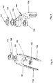
- FIGS. 1 and 2 show a caster assembly 10 having a caster bracket in the form of a caster fork 12, a caster 14, a pivot post 16, a bearing 18, and a cylinder housing 20 connectable to a wheelchair frame, not shown.
- the caster 14 is rotatably supported about a caster roller shaft 22 by the caster fork 12, while the caster fork 12 is rotatable about a first axis of rotation A1, thanks to the bearing 18, relative to the pivot post 16.
- the bearing 18 includes a raceway 18 a, communicates with a spacer ring 24 in connection and has various bearing elements, which are separated by a disc 26 on.
- the pivot post 16 in turn comprises a shaft 28 a, which is adapted to the raceway 18 a of the bearing 18, and a bolt 28 with which the pivot post 16 is screwed into a rotary sleeve 30 within the cylinder housing 20.
- the rotary sleeve 30 has a through hole 30a for a pivot pin 32, the pivot pin 32 further passing through the cylinder housing 20 and a second rotation axis A2 determines around which the pivot post 16 is pivotable together with the pivot roller fork 12.
- a Rad Wegnanpassung In wheelchairs, it is advantageous to be able to make a Rad Wegnanpassung that requires the need for a precise adjustment of the pivot angle of the pivot post 16.
- the angular position can in turn be fixed by a profile arrangement 34, which in turn has an upper profile 36 with a gap 36a and a tooth profile 36b, which in a tooth profile 38b of a lower profile 38, as in the context of EP 1 532 007 B1 described, engages.
- the EP 1 812 250 B1 as well as the parallel US 2005/0028319 A1 deals with the adjustability of the angular position of the pivot post 16 and suggests in this context the use of screws. More specifically, there is an adjusting screw used, which is screwed into an upper end of the rotary sleeve 30 so that it can be brought into engagement with the pivot pin 32.
- a disadvantage of the known arrangements is that the swivel forks tend to flutter during a driving operation.
- the US 5,167,048 describes a caster retainer wherein stiffening is effected by a spring washer which can apply pressure perpendicular to the axis of rotation of a caster bracket relative to a pivot post and thus parallel to a bearing of the pivot post.
- an adjustable caster assembly in which a bearing with interlocking members is used between a caster bracket and a pivot post to reduce flutter.
- the EP 2 505 384 A1 relates to a wheelchair in which the angular position of a rotation axis of a roller with respect to the frame of the wheelchair is continuously and continuously adjustable.
- a castor wheel assembly may be connected by a transverse axis with a frame portion.
- An adjustable locking mechanism prevents the Swivel castor pivoted by the Lenkrollenanordnug is blocked in the desired angular position.
- a steering roller holding device which prevents flapping of a steering roller and is easily adjustable.
- the device comprises a shaft receiving chamber, in which a bushing is arranged with bearing elements.
- An adjustable locking device secures the shaft assembly in the socket and is positioned at an opening of the receiving chamber.
- the device may include first and second collars for adjusting a preload of the bearings.
- a steering roller device has a U-shaped cap with an upper web portion and two adjacent downwardly extending leg portions to define a castor receiving space.
- a steering roller is rotatably mounted in space, the cap partially covers the castor.
- the cap includes a colloidal bearing cup integrally formed to receive and support a bearing assembly and attaching one end of a structural support shaft.
- a pivot head with a hole in the middle is placed on the cap and allows an opposite end of the shaft to protrude.
- a brake mechanism supported by the cap may be operated to inhibit rotation of the steering roller.
- a front fork that carries a wheel is, according to the GB 2 292 776 A formed by two separate parts. Each part has a leg section and a body section. The two parts are clamped together by means of screws or bolts and receive a bearing ring in which a support element of a part is attached to which the wheel is to be attached. The two parts may alternatively be fastened by means of a sleeve or cap.
- the US 2008/0209673 describes a caster assembly having a caster mount attachable to a frame of a mobile device and engaging a caster fork, and a biasing device that restricts the rotation of a caster shaft and thereby prevents flapping and drifting so that the mobile device is in its lane remains.
- the biasing means may be such that the roller shaft defines at least one vertical notch therein and a spring piston is located in the roller support.
- the spring piston has an internal spring and a movable ball member on the spring corresponding to the spring Castor shaft faces so that the ball is biased against the roller shaft and is in the roller shaft notch when the roller shaft is in a desired rotational position.
- the biasing device can also use magnets on the roller shaft and the roller holder are aligned with opposite Anziehungspolen when the roller is in a desired position.
- Other roller arrangements are from the GB 402,156 and the US 4,432,116 known.
- Object of the present invention is to develop the generic caster assembly such that the disadvantages of the prior art are overcome, in particular that structurally simple flutter of the caster is avoided.
- the bearing between the pivot post and the caster bracket can be directly wedged, so that a force acts on the wedged bearing perpendicular to the axis of rotation of the pivot post relative to the caster support, which inhibits and thus avoidance, at least reduction, causes a flutter of the caster.
- by deliberately screwing in at least one threaded pin, e.g. in the form of a grub screw targeted inhibition allows.
- pivot roller assembly comprises in a conventional manner a caster support in the form of a pivot roller fork 112, a bearing with two bearing elements 118, 148 between the pivot roller fork 112 and a pivot post, not shown, wherein between the bearing elements 118, 148 a disc 126 is arranged.
- the caster fork 112 further comprises two caster roller support arms in the form of Schwenkrollengabelarme 112 a, 112 b, between which a pivot roller, not shown, is rotatably arrangeable.
- a threaded pin 200 is used which can be screwed into the swivel roller assembly 10 so as to clamp it to the upper bearing element 113 for bracing attacks. More precisely, wedging results in wedging, which results in a force being built up perpendicular to the axis of rotation A3 which causes an obstruction.
- FIG. 4 which in turn has a caster bracket 112 'with only one caster support arm 112'a, two bearing members 118', 148 'and a pulley 126' will wobble the caster bracket 112 'when rotated about the axis A3' (second pivot axis) by screwing a Threaded pin 200 'in the caster bracket 112' for the purpose of engaging the upper bearing element 118 'avoided by targeted bracing thereof.
Landscapes
- Health & Medical Sciences (AREA)
- Life Sciences & Earth Sciences (AREA)
- Animal Behavior & Ethology (AREA)
- General Health & Medical Sciences (AREA)
- Public Health (AREA)
- Veterinary Medicine (AREA)
- Engineering & Computer Science (AREA)
- Mechanical Engineering (AREA)
- Handcart (AREA)
Claims (5)
- Ensemble de roulettes pivotantes pour un fauteuil roulant, comprenant
une tige de pivotement qui peut pivoter autour d'un premier axe de rotation à l'intérieur d'un boîtier de châssis de fauteuil roulant,
une fourche de roulette pivotante (112, 112') qui peut pivoter avec la tige de pivotement autour du premier axe de rotation et qui est rotative par rapport à la tige de pivotement autour d'un deuxième axe de rotation A3, A3' s'étendant perpendiculairement au premier axe de rotation avec interposition d'un palier (118, 118', 148, 148'), et
une roulette pivotante qui est supportée par la fourche de roulette pivotante de façon rotative autour d'un troisième axe de rotation s'étendant parallèlement au premier axe, caractérisé par
au moins un élément de serrage sous la forme d'au moins une tige filetée (200, 200') pour le serrage du palier (118, 118', 148, 148'), dans lequel une première tige filetée (200) engage le palier (118, 148) par le bas dans la direction du boîtier de châssis de fauteuil roulant et bloque spécifiquement le palier par vissage unidirectionnel, et/ou
une deuxième tige filetée (200') engage le palier (118', 148') à travers un support de roulette pivotante du boîtier de châssis de fauteuil roulant sous la forme de la fourche de roulette pivotante (112') et bloque spécifiquement le palier par vissage unidirectionnel. - Ensemble de roulettes pivotantes selon la revendication 1, caractérisé en ce que le palier a un élément de palier supérieur (118') tourné à l'opposé de la roulette pivotante et un élément de palier inférieur (148') tourné vers la roulette pivotante, et la deuxième tige filetée (200') engage l'élément de palier supérieur (118'), dans lequel de préférence un disque ou une entretoise (126') est disposé(e) entre les éléments de palier (118', 148').
- Ensemble de roulettes pivotantes selon la revendication 1 ou 2, caractérisé en ce que la première tige filetée (200) engage le palier (118, 148) par le bas dans la direction du boîtier de châssis de fauteuil roulant parallèlement au deuxième axe de rotation A3, A3'.
- Ensemble de roulettes pivotantes selon l'une quelconque des revendications précédentes, caractérisé en ce que
la deuxième tige filetée (200') engage le palier (118', 148') à travers le boîtier de châssis de fauteuil roulant perpendiculairement au deuxième axe de rotation A3, A3'. - Ensemble de roulettes pivotantes selon l'une quelconque des revendications précédentes, caractérisé en ce que
la première et/ou la deuxième tige filetée (200, 200') est formée comme vis sans tête.
Applications Claiming Priority (1)
| Application Number | Priority Date | Filing Date | Title |
|---|---|---|---|
| DE202013102319U DE202013102319U1 (de) | 2013-05-28 | 2013-05-28 | Schwenkrollenbaugruppe für einen Rollstuhl |
Publications (2)
| Publication Number | Publication Date |
|---|---|
| EP2811192A1 EP2811192A1 (fr) | 2014-12-10 |
| EP2811192B1 true EP2811192B1 (fr) | 2019-08-07 |
Family
ID=48784277
Family Applications (1)
| Application Number | Title | Priority Date | Filing Date |
|---|---|---|---|
| EP14170070.8A Active EP2811192B1 (fr) | 2013-05-28 | 2014-05-27 | Ensemble de roues pivotantes pour fauteuil roulant |
Country Status (2)
| Country | Link |
|---|---|
| EP (1) | EP2811192B1 (fr) |
| DE (1) | DE202013102319U1 (fr) |
Families Citing this family (1)
| Publication number | Priority date | Publication date | Assignee | Title |
|---|---|---|---|---|
| CN109291736B (zh) * | 2018-11-02 | 2023-09-29 | 济南大学 | 一种纺织机械用防阻塞车轮 |
Family Cites Families (13)
| Publication number | Priority date | Publication date | Assignee | Title |
|---|---|---|---|---|
| GB402156A (en) * | 1932-06-02 | 1933-11-30 | Whitfields Bedsteads Ltd | Improvements relating to castors |
| US4432116A (en) * | 1981-04-06 | 1984-02-21 | Houdaille Industries, Inc. | Caster shimmy damper including a viscous damping medium |
| US4969232A (en) | 1989-08-03 | 1990-11-13 | Everest & Jennings, Inc. | Adjustable caster wheel assembly |
| US5167048A (en) | 1991-05-10 | 1992-12-01 | Medical Composite Technology | Caster wheel retention device |
| US5390393A (en) * | 1993-01-22 | 1995-02-21 | Metro Industries, Inc. | Caster with a fouling-resistant bearing cup feature |
| GB2292776A (en) * | 1994-09-01 | 1996-03-06 | Colson Castors Uk | Castor fork |
| DE10106688A1 (de) * | 2001-02-14 | 2002-09-26 | Rolli Mobil Gmbh | Lagerung einer Lenkgabel |
| US6796568B2 (en) * | 2002-05-01 | 2004-09-28 | Pride Mobility Products Corporation | Suspension system for a wheelchair |
| US7231689B2 (en) | 2002-06-05 | 2007-06-19 | Sunrise Medical Hhg Inc. | Adjustable wheel assembly |
| US7353566B2 (en) * | 2002-06-05 | 2008-04-08 | Sunrise Medical Hhg Inc. | Adjustable wheel assembly |
| US6944910B2 (en) * | 2002-07-03 | 2005-09-20 | Sunrise Medical Hhg Inc. | Caster wheel assembly with anti-flutter control |
| US20080209673A1 (en) * | 2007-02-23 | 2008-09-04 | Cooper Rory A | Caster and system for mobile device |
| EP2505384A1 (fr) * | 2011-04-01 | 2012-10-03 | Invacare International Sàrl | Fauteuil roulant doté d'un réglage de l'axe de pivotement de la roue pivotante |
-
2013
- 2013-05-28 DE DE202013102319U patent/DE202013102319U1/de not_active Expired - Lifetime
-
2014
- 2014-05-27 EP EP14170070.8A patent/EP2811192B1/fr active Active
Also Published As
| Publication number | Publication date |
|---|---|
| EP2811192A1 (fr) | 2014-12-10 |
| DE202013102319U1 (de) | 2013-06-11 |
Similar Documents
| Publication | Publication Date | Title |
|---|---|---|
| EP3271538B1 (fr) | Charnière pour porte ou fenêtre | |
| EP2612053B1 (fr) | Poulie de tension à excentrique | |
| EP2423151B2 (fr) | Dispositif de capteur angulaire de rotation à équilibrage de jeu radial | |
| DE10229740A1 (de) | Einstellbare Vorderachs- und Bremsträgerkonstruktion | |
| DE10320639A1 (de) | Nockerwellenversteller für Fahrzeuge, vorzugsweise für Kraftfahrzeuge | |
| DE2914844C2 (de) | Schnellspannvorrichtung, insbesondere für Auswuchtmaschinen zum Auswuchten von Fahrzeugrädern | |
| DE102014118583A1 (de) | Fahrzeugzylindereinspannvorrichtung und Einspanngruppenelement | |
| EP0195973B1 (fr) | Dispositif à chaînes centrifugées pour véhicules automobiles | |
| EP2811192B1 (fr) | Ensemble de roues pivotantes pour fauteuil roulant | |
| DE202015101929U1 (de) | Bremsscheiben-Abdeckeinheit | |
| DE10316190A1 (de) | Klemmvorrichtung zur Lagefixierung einer Lenksäule | |
| EP0215281A2 (fr) | Palier pour un battant de fenêtre, porte ou similaire | |
| EP0992226A2 (fr) | Fauteuil roulant | |
| DE69614840T2 (de) | Lösbare nabe für die montage eines drehenden teils auf einer antriebswelle und mit einer lösbaren nabe dieser art versehendes drehendes teil | |
| DE29614386U1 (de) | Mit einem aushängbaren Türscharnier baulich vereinigter Türfeststeller | |
| EP3334636B1 (fr) | Dispositif de serrage pour une colonne de direction pour un véhicule à moteur | |
| DE102004026286B4 (de) | Motorradständer | |
| CH688896A5 (de) | Zaun, insbesondere Maschinenschutzzaun. | |
| DE202004008553U1 (de) | Motorradständer | |
| DE9116993U1 (de) | Rollapparat für daran insbesondere hängegelagerte Schiebetüren o.dgl. | |
| DE202010001441U1 (de) | Justiersystem für Bauelemente | |
| DE202016106025U1 (de) | Vorrichtung zur stufenlosen Einstellung des Endanschlags | |
| DE29804596U1 (de) | Haltevorrichtung für Rollstuhlfahrräder | |
| DE102004027396B3 (de) | Bohrkronenrohr | |
| DE102011111695B4 (de) | Hinterradschwinge für ein Motorrad |
Legal Events
| Date | Code | Title | Description |
|---|---|---|---|
| PUAI | Public reference made under article 153(3) epc to a published international application that has entered the european phase |
Free format text: ORIGINAL CODE: 0009012 |
|
| 17P | Request for examination filed |
Effective date: 20140527 |
|
| AK | Designated contracting states |
Kind code of ref document: A1 Designated state(s): AL AT BE BG CH CY CZ DE DK EE ES FI FR GB GR HR HU IE IS IT LI LT LU LV MC MK MT NL NO PL PT RO RS SE SI SK SM TR |
|
| AX | Request for extension of the european patent |
Extension state: BA ME |
|
| R17P | Request for examination filed (corrected) |
Effective date: 20150528 |
|
| RBV | Designated contracting states (corrected) |
Designated state(s): AL AT BE BG CH CY CZ DE DK EE ES FI FR GB GR HR HU IE IS IT LI LT LU LV MC MK MT NL NO PL PT RO RS SE SI SK SM TR |
|
| RAP1 | Party data changed (applicant data changed or rights of an application transferred) |
Owner name: SUNRISE MEDICAL GMBH |
|
| GRAP | Despatch of communication of intention to grant a patent |
Free format text: ORIGINAL CODE: EPIDOSNIGR1 |
|
| STAA | Information on the status of an ep patent application or granted ep patent |
Free format text: STATUS: GRANT OF PATENT IS INTENDED |
|
| INTG | Intention to grant announced |
Effective date: 20190307 |
|
| GRAS | Grant fee paid |
Free format text: ORIGINAL CODE: EPIDOSNIGR3 |
|
| GRAA | (expected) grant |
Free format text: ORIGINAL CODE: 0009210 |
|
| STAA | Information on the status of an ep patent application or granted ep patent |
Free format text: STATUS: THE PATENT HAS BEEN GRANTED |
|
| AK | Designated contracting states |
Kind code of ref document: B1 Designated state(s): AL AT BE BG CH CY CZ DE DK EE ES FI FR GB GR HR HU IE IS IT LI LT LU LV MC MK MT NL NO PL PT RO RS SE SI SK SM TR |
|
| REG | Reference to a national code |
Ref country code: GB Ref legal event code: FG4D Free format text: NOT ENGLISH |
|
| REG | Reference to a national code |
Ref country code: CH Ref legal event code: EP Ref country code: AT Ref legal event code: REF Ref document number: 1164351 Country of ref document: AT Kind code of ref document: T Effective date: 20190815 |
|
| REG | Reference to a national code |
Ref country code: DE Ref legal event code: R096 Ref document number: 502014012355 Country of ref document: DE |
|
| REG | Reference to a national code |
Ref country code: IE Ref legal event code: FG4D Free format text: LANGUAGE OF EP DOCUMENT: GERMAN |
|
| REG | Reference to a national code |
Ref country code: NL Ref legal event code: MP Effective date: 20190807 |
|
| REG | Reference to a national code |
Ref country code: LT Ref legal event code: MG4D |
|
| PG25 | Lapsed in a contracting state [announced via postgrant information from national office to epo] |
Ref country code: LT Free format text: LAPSE BECAUSE OF FAILURE TO SUBMIT A TRANSLATION OF THE DESCRIPTION OR TO PAY THE FEE WITHIN THE PRESCRIBED TIME-LIMIT Effective date: 20190807 Ref country code: HR Free format text: LAPSE BECAUSE OF FAILURE TO SUBMIT A TRANSLATION OF THE DESCRIPTION OR TO PAY THE FEE WITHIN THE PRESCRIBED TIME-LIMIT Effective date: 20190807 Ref country code: NL Free format text: LAPSE BECAUSE OF FAILURE TO SUBMIT A TRANSLATION OF THE DESCRIPTION OR TO PAY THE FEE WITHIN THE PRESCRIBED TIME-LIMIT Effective date: 20190807 Ref country code: NO Free format text: LAPSE BECAUSE OF FAILURE TO SUBMIT A TRANSLATION OF THE DESCRIPTION OR TO PAY THE FEE WITHIN THE PRESCRIBED TIME-LIMIT Effective date: 20191107 Ref country code: BG Free format text: LAPSE BECAUSE OF FAILURE TO SUBMIT A TRANSLATION OF THE DESCRIPTION OR TO PAY THE FEE WITHIN THE PRESCRIBED TIME-LIMIT Effective date: 20191107 Ref country code: PT Free format text: LAPSE BECAUSE OF FAILURE TO SUBMIT A TRANSLATION OF THE DESCRIPTION OR TO PAY THE FEE WITHIN THE PRESCRIBED TIME-LIMIT Effective date: 20191209 Ref country code: SE Free format text: LAPSE BECAUSE OF FAILURE TO SUBMIT A TRANSLATION OF THE DESCRIPTION OR TO PAY THE FEE WITHIN THE PRESCRIBED TIME-LIMIT Effective date: 20190807 Ref country code: FI Free format text: LAPSE BECAUSE OF FAILURE TO SUBMIT A TRANSLATION OF THE DESCRIPTION OR TO PAY THE FEE WITHIN THE PRESCRIBED TIME-LIMIT Effective date: 20190807 |
|
| PG25 | Lapsed in a contracting state [announced via postgrant information from national office to epo] |
Ref country code: IS Free format text: LAPSE BECAUSE OF FAILURE TO SUBMIT A TRANSLATION OF THE DESCRIPTION OR TO PAY THE FEE WITHIN THE PRESCRIBED TIME-LIMIT Effective date: 20191207 Ref country code: ES Free format text: LAPSE BECAUSE OF FAILURE TO SUBMIT A TRANSLATION OF THE DESCRIPTION OR TO PAY THE FEE WITHIN THE PRESCRIBED TIME-LIMIT Effective date: 20190807 Ref country code: GR Free format text: LAPSE BECAUSE OF FAILURE TO SUBMIT A TRANSLATION OF THE DESCRIPTION OR TO PAY THE FEE WITHIN THE PRESCRIBED TIME-LIMIT Effective date: 20191108 Ref country code: RS Free format text: LAPSE BECAUSE OF FAILURE TO SUBMIT A TRANSLATION OF THE DESCRIPTION OR TO PAY THE FEE WITHIN THE PRESCRIBED TIME-LIMIT Effective date: 20190807 Ref country code: AL Free format text: LAPSE BECAUSE OF FAILURE TO SUBMIT A TRANSLATION OF THE DESCRIPTION OR TO PAY THE FEE WITHIN THE PRESCRIBED TIME-LIMIT Effective date: 20190807 Ref country code: LV Free format text: LAPSE BECAUSE OF FAILURE TO SUBMIT A TRANSLATION OF THE DESCRIPTION OR TO PAY THE FEE WITHIN THE PRESCRIBED TIME-LIMIT Effective date: 20190807 |
|
| PG25 | Lapsed in a contracting state [announced via postgrant information from national office to epo] |
Ref country code: TR Free format text: LAPSE BECAUSE OF FAILURE TO SUBMIT A TRANSLATION OF THE DESCRIPTION OR TO PAY THE FEE WITHIN THE PRESCRIBED TIME-LIMIT Effective date: 20190807 |
|
| PG25 | Lapsed in a contracting state [announced via postgrant information from national office to epo] |
Ref country code: IT Free format text: LAPSE BECAUSE OF FAILURE TO SUBMIT A TRANSLATION OF THE DESCRIPTION OR TO PAY THE FEE WITHIN THE PRESCRIBED TIME-LIMIT Effective date: 20190807 Ref country code: RO Free format text: LAPSE BECAUSE OF FAILURE TO SUBMIT A TRANSLATION OF THE DESCRIPTION OR TO PAY THE FEE WITHIN THE PRESCRIBED TIME-LIMIT Effective date: 20190807 Ref country code: DK Free format text: LAPSE BECAUSE OF FAILURE TO SUBMIT A TRANSLATION OF THE DESCRIPTION OR TO PAY THE FEE WITHIN THE PRESCRIBED TIME-LIMIT Effective date: 20190807 Ref country code: EE Free format text: LAPSE BECAUSE OF FAILURE TO SUBMIT A TRANSLATION OF THE DESCRIPTION OR TO PAY THE FEE WITHIN THE PRESCRIBED TIME-LIMIT Effective date: 20190807 Ref country code: PL Free format text: LAPSE BECAUSE OF FAILURE TO SUBMIT A TRANSLATION OF THE DESCRIPTION OR TO PAY THE FEE WITHIN THE PRESCRIBED TIME-LIMIT Effective date: 20190807 |
|
| PG25 | Lapsed in a contracting state [announced via postgrant information from national office to epo] |
Ref country code: SK Free format text: LAPSE BECAUSE OF FAILURE TO SUBMIT A TRANSLATION OF THE DESCRIPTION OR TO PAY THE FEE WITHIN THE PRESCRIBED TIME-LIMIT Effective date: 20190807 Ref country code: SM Free format text: LAPSE BECAUSE OF FAILURE TO SUBMIT A TRANSLATION OF THE DESCRIPTION OR TO PAY THE FEE WITHIN THE PRESCRIBED TIME-LIMIT Effective date: 20190807 Ref country code: CZ Free format text: LAPSE BECAUSE OF FAILURE TO SUBMIT A TRANSLATION OF THE DESCRIPTION OR TO PAY THE FEE WITHIN THE PRESCRIBED TIME-LIMIT Effective date: 20190807 Ref country code: IS Free format text: LAPSE BECAUSE OF FAILURE TO SUBMIT A TRANSLATION OF THE DESCRIPTION OR TO PAY THE FEE WITHIN THE PRESCRIBED TIME-LIMIT Effective date: 20200224 |
|
| REG | Reference to a national code |
Ref country code: DE Ref legal event code: R097 Ref document number: 502014012355 Country of ref document: DE |
|
| PLBE | No opposition filed within time limit |
Free format text: ORIGINAL CODE: 0009261 |
|
| STAA | Information on the status of an ep patent application or granted ep patent |
Free format text: STATUS: NO OPPOSITION FILED WITHIN TIME LIMIT |
|
| PG2D | Information on lapse in contracting state deleted |
Ref country code: IS |
|
| 26N | No opposition filed |
Effective date: 20200603 |
|
| PG25 | Lapsed in a contracting state [announced via postgrant information from national office to epo] |
Ref country code: SI Free format text: LAPSE BECAUSE OF FAILURE TO SUBMIT A TRANSLATION OF THE DESCRIPTION OR TO PAY THE FEE WITHIN THE PRESCRIBED TIME-LIMIT Effective date: 20190807 |
|
| PG25 | Lapsed in a contracting state [announced via postgrant information from national office to epo] |
Ref country code: CH Free format text: LAPSE BECAUSE OF NON-PAYMENT OF DUE FEES Effective date: 20200531 Ref country code: LI Free format text: LAPSE BECAUSE OF NON-PAYMENT OF DUE FEES Effective date: 20200531 Ref country code: MC Free format text: LAPSE BECAUSE OF FAILURE TO SUBMIT A TRANSLATION OF THE DESCRIPTION OR TO PAY THE FEE WITHIN THE PRESCRIBED TIME-LIMIT Effective date: 20190807 |
|
| REG | Reference to a national code |
Ref country code: BE Ref legal event code: MM Effective date: 20200531 |
|
| GBPC | Gb: european patent ceased through non-payment of renewal fee |
Effective date: 20200527 |
|
| PG25 | Lapsed in a contracting state [announced via postgrant information from national office to epo] |
Ref country code: LU Free format text: LAPSE BECAUSE OF NON-PAYMENT OF DUE FEES Effective date: 20200527 |
|
| PG25 | Lapsed in a contracting state [announced via postgrant information from national office to epo] |
Ref country code: GB Free format text: LAPSE BECAUSE OF NON-PAYMENT OF DUE FEES Effective date: 20200527 Ref country code: IE Free format text: LAPSE BECAUSE OF NON-PAYMENT OF DUE FEES Effective date: 20200527 Ref country code: FR Free format text: LAPSE BECAUSE OF NON-PAYMENT OF DUE FEES Effective date: 20200531 |
|
| PG25 | Lapsed in a contracting state [announced via postgrant information from national office to epo] |
Ref country code: BE Free format text: LAPSE BECAUSE OF NON-PAYMENT OF DUE FEES Effective date: 20200531 |
|
| REG | Reference to a national code |
Ref country code: AT Ref legal event code: MM01 Ref document number: 1164351 Country of ref document: AT Kind code of ref document: T Effective date: 20200527 |
|
| PG25 | Lapsed in a contracting state [announced via postgrant information from national office to epo] |
Ref country code: AT Free format text: LAPSE BECAUSE OF NON-PAYMENT OF DUE FEES Effective date: 20200527 |
|
| PG25 | Lapsed in a contracting state [announced via postgrant information from national office to epo] |
Ref country code: MT Free format text: LAPSE BECAUSE OF FAILURE TO SUBMIT A TRANSLATION OF THE DESCRIPTION OR TO PAY THE FEE WITHIN THE PRESCRIBED TIME-LIMIT Effective date: 20190807 Ref country code: CY Free format text: LAPSE BECAUSE OF FAILURE TO SUBMIT A TRANSLATION OF THE DESCRIPTION OR TO PAY THE FEE WITHIN THE PRESCRIBED TIME-LIMIT Effective date: 20190807 |
|
| PG25 | Lapsed in a contracting state [announced via postgrant information from national office to epo] |
Ref country code: MK Free format text: LAPSE BECAUSE OF FAILURE TO SUBMIT A TRANSLATION OF THE DESCRIPTION OR TO PAY THE FEE WITHIN THE PRESCRIBED TIME-LIMIT Effective date: 20190807 |
|
| P01 | Opt-out of the competence of the unified patent court (upc) registered |
Effective date: 20230619 |
|
| PGFP | Annual fee paid to national office [announced via postgrant information from national office to epo] |
Ref country code: DE Payment date: 20250519 Year of fee payment: 12 |