EP2811594B1 - Vorrichtung zur Durchführung oder Befestigung von Leitungen in einem Verteilerschrank - Google Patents
Vorrichtung zur Durchführung oder Befestigung von Leitungen in einem Verteilerschrank Download PDFInfo
- Publication number
- EP2811594B1 EP2811594B1 EP14170870.1A EP14170870A EP2811594B1 EP 2811594 B1 EP2811594 B1 EP 2811594B1 EP 14170870 A EP14170870 A EP 14170870A EP 2811594 B1 EP2811594 B1 EP 2811594B1
- Authority
- EP
- European Patent Office
- Prior art keywords
- cables
- distribution device
- pipes
- distribution cabinet
- fixation
- Prior art date
- Legal status (The legal status is an assumption and is not a legal conclusion. Google has not performed a legal analysis and makes no representation as to the accuracy of the status listed.)
- Active
Links
Images



Classifications
-
- H—ELECTRICITY
- H02—GENERATION; CONVERSION OR DISTRIBUTION OF ELECTRIC POWER
- H02B—BOARDS, SUBSTATIONS OR SWITCHING ARRANGEMENTS FOR THE SUPPLY OR DISTRIBUTION OF ELECTRIC POWER
- H02B1/00—Frameworks, boards, panels, desks, casings; Details of substations or switching arrangements
- H02B1/26—Casings; Parts thereof or accessories therefor
- H02B1/30—Cabinet-type casings; Parts thereof or accessories therefor
- H02B1/305—Cable entries
-
- H—ELECTRICITY
- H02—GENERATION; CONVERSION OR DISTRIBUTION OF ELECTRIC POWER
- H02G—INSTALLATION OF ELECTRIC CABLES OR LINES, OR OF COMBINED OPTICAL AND ELECTRIC CABLES OR LINES
- H02G3/00—Installations of electric cables or lines or protective tubing therefor in or on buildings, equivalent structures or vehicles
- H02G3/02—Details
- H02G3/08—Distribution boxes; Connection or junction boxes
- H02G3/081—Bases, casings or covers
- H02G3/083—Inlets
-
- H—ELECTRICITY
- H02—GENERATION; CONVERSION OR DISTRIBUTION OF ELECTRIC POWER
- H02G—INSTALLATION OF ELECTRIC CABLES OR LINES, OR OF COMBINED OPTICAL AND ELECTRIC CABLES OR LINES
- H02G3/00—Installations of electric cables or lines or protective tubing therefor in or on buildings, equivalent structures or vehicles
- H02G3/30—Installations of cables or lines on walls, floors or ceilings
- H02G3/32—Installations of cables or lines on walls, floors or ceilings using mounting clamps
Definitions
- the invention relates to a device for guiding lines, in particular cables or pipes, through the wall of a distribution cabinet for telecommunications.
- distribution cabinets can in particular also be used outdoors and are used to connect local distribution networks to underground cables, in particular to optical waveguides laid by means of underground cables.
- the distribution cabinets have components such as splice modules, by means of which the corresponding fiber connections can be established. For this it is necessary to lead the lines into the interior of the distribution cabinet after they exit the ground.
- appropriate holes are either drilled on site at a suitable point in the wall of the cabinet or prefabricated plastic or rubber elements with predetermined breakout points are used. What both variants have in common is the comparatively complex production of suitable openings for the lines on site.
- U.S. 5,422,436 with a cabinet in which cables are inserted through rail-like inserts in the bottom of the cabinet, whereby various inserts for different types of cables can be accommodated in the rails.
- DE 198 51 952 C1 a control cabinet with various rail-like inserts in its base for the sealed entry of cables of different thicknesses.
- the German utility model 77 18 935 shows a cable distribution cabinet for construction sites, campsites and festival areas, under the floor of which an inclined plate with a strain relief rail is attached.
- DE 199 61 244 C1 shows a housing for receiving electrical elements, which has cable entry elements with seals in a side wall. Finally shows the JP S63 198308 U a cabinet with plate-like elements apparently intended for the cable duct.
- the WO 2005/107028 A1 shows an installation distributor housing, for example as a feeder box, for power cables, with at least one side wall with an entry plate for the cables rotated by about 45 ° against the direction of a busbar system in the box with regard to cables with a particularly thick cross section. This can also affect two such side walls.
- the preamble of claim 1 is based on this document.
- the DE 103 46 742 A1 a feed-through device for passing cables or lines through a wall, wherein an outlet side of this device can be at an angle between 70 ° and 120 ° to its wall-parallel and thus vertical inlet side.
- the object of the present invention is to specify a distributor device which enables a simple implementation of lines through a wall of the device, which is advantageous compared to the prior art.
- the distribution device is a distribution cabinet.
- a lead-through or fastening of lines, in particular of pipes or cables, in a distribution cabinet can be designed as a so-called change element.
- a V-shaped entry shaft for the passage of lines which has the interchangeable element, is formed in a wall surface of the distribution cabinet.
- This wall surface represents a center piece of the distribution cabinet.
- An interchangeable element designed as an interchangeable plate for the passage of lines, in particular cables or pipes, which can have different radii of passage openings, is particularly advantageous here. Furthermore, passage openings of only a certain radius can also be present on such a removable plate, which can vary from removable plate to removable plate. Due to the flexibility gained in this way and the associated provision of a wide variety of interchangeable plates with the most varied of diameter of the passage openings, the previous drilling of plates or walls on site in the field is no longer necessary.
- the removable plate can in particular be formed using a steel sheet of suitable thickness.
- the passage openings can be provided with seals, in particular with rubber seals. It is advantageous if the removable plates have a rectangular basic shape.
- the side length of the rectangle can be selected to be constant for all radii of passage openings, so that the removable plates can easily be interchanged.
- Distribution cabinets can also be provided with appropriate openings for the removable plates practically at the factory, so that only the appropriate removable plate has to be used on site and there is no need to drill through or otherwise break through walls. Unused receiving openings can be closed with dummy plates, i.e. removable plates without passage openings.
- the interchangeable element which is used to fasten lines, is designed as a cross rail and, for example is connected to a C-profile rail via fastening straps.
- the cross rail can also be used as a flat element be trained.
- a cross rail described above has a longitudinal slot and a plurality of bores, in particular threaded bores.
- This makes it possible to attach a large number of cable routing elements, such as hammer head pipe clamps, busbars or so-called combs, these cable routing elements being displaceable along the cross rail as well as together with the cross rail along the C-profile rail, thus providing a high level of flexibility in arrangement is.
- the cross rail for fastening cables or pipes is designed vertically or horizontally to the plane formed by the C-profile rails, so that there is also a high degree of flexibility with regard to the spatial arrangement of cable routing elements.
- the distribution cabinet can also be constructed in two parts in such a way that an upper part is accessible separately from a lower part.
- the upper part can in particular contain splice modules, whereas the lower part stands on the ground and, for example - in the case of a cabinet for the outside area - receives cables emerging from the ground. This is particularly advantageous, as it can be ensured that any contamination caused by working on the lines laid in the lower part of the cabinet does not contaminate the upper part.
- Figure 1 shows schematically a distribution cabinet in which the invention can be implemented.
- the distribution cabinet 1 shows a two-part structure with a splice and patch area 2 in the upper part and a lower part for cable entry 3.
- the splice and patch area 2 shows, in a manner known per se, splice modules and components for routing cables.
- a V-shaped entry shaft 4 is formed, through which the cables, not shown here, can be guided from the lower part 3 into the splice and patch area 2.
- conventional cable bushings 15 in the flat bottom surface of a distribution cabinet 1.
- the doors of the lower part 3, not shown here are accessible separately from the upper part 2. This enables any “dirty” work to take place only in the lower part 3 of the distribution cabinet 1 without contaminating the upper part, the splice and patch area 2.
- FIG. 2 shows a conventional cable bushing 5, as it is in particular in the lower part of the splice and patch area 2 for the implementation of Optical fibers or the like can be used.
- the cable bushing 5 is formed from an elastic material such as a hard rubber and has an essentially cuboid basic shape as well as a plurality of prepared passage areas 6 for cables, which can be opened by means of a suitable tool if necessary.
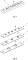
- FIG 3 three removable disks 7 according to the invention are shown as examples.
- the removable plates 7 have a metallic, rectangular base body which is provided with prefabricated through openings 8.
- the interchangeable plates 7 shown here show, by way of example, passage openings 8 with three different radii in order to illustrate that a large number of such interchangeable plates 7 with appropriately prepared passage openings 8 can be kept.
- the removable plates 7 with regard to their dimensions, in particular the edge length of the base support according to the in Figure 2 conventional cable bushing 5 shown in particular are designed according to the dimensions of the base area of the cable bushing 5. This way it becomes possible to get that out Figure 2 known elements against the in Figure 3 to replace shown removable plates 7 or vice versa or to use combinations of the elements shown.
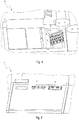
- FIG. 5 Another embodiment is in Figure 5 shown where different removable plates 7 or, if the openings are not in use, so-called dummy plates 7 'are integrated in the flat bottom surface of a distribution cabinet 1.
- FIG 6 shows another advantageous way of making cable routing more flexible in distribution cabinets.
- C-profile rails 9 arranged in the bottom area of a distribution cabinet 1 are shown, on which cross rails 10 for fastening guide elements 11 for
- the transverse rails 10 can be displaced practically continuously along the C-profile rails 9 and thus enable an extremely flexible arrangement of cable routing elements 11.
- FIG 7 an exemplary transverse rail 10 'is shown, which is referred to below as a horizontal rail. It has two fastening tabs 12 with screws for fastening to the C-profile rails 9 mentioned above, as well as a longitudinal slot 13 and a plurality of bores 14, in particular threaded bores.
- the rail 10 ′′ shown is designed as a vertical rail, which runs essentially vertically to the plane formed by the C-profile rails 9. What is common to the rails 10 ′ and 10 ′′ is as shown in FIG Figure 8 It can be seen, the longitudinal slot 13 as well as the threaded holes 14 and the fastening tabs 12. In the Figures 9 to 11 it can be seen what degree of flexibility with regard to the fastening and arrangement of cable guide elements 11 is offered by the modular rail system shown. So is in figure 9 Shown as an example, how hammer head pipe clamps 11 'are connected to a cross rail 10' and can be used for guiding individual cables or bundles of cables.
- the pipe clamps 11 ' can be displaced along the cross rail 10' as well as together with the cross rail along the C-profile rails 9, so that practically every point in the plane formed from the C-profile rails can be approached with a pipe clamp.
- Figure 11 shows a variant in which so-called combs 11 '′′ for guiding tubes, in which cables can even be guided, are fastened to a vertical cross rail 10 ′′ by screwing them into the threaded bores 14.
- combs 11 '′′ for guiding tubes in which cables can even be guided, are fastened to a vertical cross rail 10 ′′ by screwing them into the threaded bores 14.
Landscapes
- Engineering & Computer Science (AREA)
- Power Engineering (AREA)
- Light Guides In General And Applications Therefor (AREA)
- Installation Of Indoor Wiring (AREA)
Description
- Die Erfindung betrifft eine Vorrichtung zur Durchführung von Leitungen, insbesondere Kabel oder Rohre, durch die Wandung eines Verteilerschrankes für die Telekommunikation. Derartige Verteilerschränke können insbesondere auch im Außenbereich Anwendung finden und dienen dem Anschluss lokaler Verteilernetze an Erdkabel, insbesondere an mittels Erdkabel verlegter Lichtwellenleiter. Dazu weisen die Verteilerschränke Komponenten wie beispielsweise Spleißmodule auf, mittels welcher die entsprechenden Faserverbindungen hergestellt werden können. Hierzu ist es erforderlich, die Leitungen nach ihrem Austritt aus dem Erdreich in das Innere des Verteilerschrankes zu führen. Nach dem Stand der Technik werden zu diesem Zweck entweder vor Ort entsprechende Löcher an passender Stelle in die Wandung des Schrankes gebohrt oder vorgefertigte Kunststoff- oder Gummielemente mit Solldurchbruchstellen verwendet. Beiden Varianten gemeinsam ist die vergleichsweise aufwendige Herstellung passender Durchbrüche für die Leitungen vor Ort.
- Zum Stand der Technik wird zunächst verwiesen auf die
US 5,422,436 mit einem Schrank, in den Kabel durch schienenartige Einsätze im Boden des Schranks eingeführt werden, wobei in den Schienen verschiedene Einsätze für verschiedene Kabeltypen untergebracht werden können. Ferner zeigt dieDE 198 51 952 C1 einen Schaltschrank mit verschiedenen schienenartigen Einsätzen in seinem Boden zur abgedichteten Einführung von unterschiedlich dicken Kabeln. Das deutsche Gebrauchsmuster 77 18 935 zeigt einen Kabelverteilerschrank für Baustellen, Campingplätze und Festplätze, unter dessen Boden eine schräg gestellte Platte mit einer Zugentlastungsschiene angebracht ist. Die -
DE 199 61 244 C1 zeigt ein Gehäuse zur Aufnahme elektrischer Elemente, das Kabeleinführungselemente mit Abdichtungen in einer Seitenwandung aufweist. Schließlich zeigt dieJP S63 198308 U - Die
WO 2005/107028 A1 zeigt ein Installationsverteilergehäuse, etwa als Einspeisekasten, für Stromkabel, wobei mit Rücksicht auf Kabel besonders dicken Querschnitts mindestens eine Seitenwand mit einer Einführungsplatte für die Kabel um etwa 45° gegen die Richtung eines Stromschienensystems in dem Kasten gedreht ist. Dies kann auch zwei solche Seitenwände betreffen. Auf diesem Dokument beruht der Oberbegriff des Anspruchs 1. - Ferner zeigt die
DE 103 46 742 A1 eine Durchführungsvorrichtung zum Durchführen von Kabeln oder Leitungen durch eine Wand, wobei eine Auslassseite dieser Vorrichtung zu deren wandparalleler und damit vertikaler Einlassseite in einem Winkel zwischen 70° und 120° liegen kann. - Aufgabe der vorliegenden Erfindung ist es, eine Verteilervorrichtung anzugeben, welche eine einfache und gegenüber dem Stand der Technik vorteilhafte Realisierung von Durchführungen von Leitungen durch eine Wandung der Vorrichtung ermöglicht.
- Diese Aufgabe wird durch die Verteilervorrichtung nach Anspruch 1 gelöst. Die Unteransprüche betreffen vorteilhafte Ausführungsformen und Varianten der Erfindung. Erfindungsgemäß ist die Verteilervorrichtung ein Verteilerschrank.
- Gemäß der vorliegenden Erfindung kann eine Durchführung oder Befestigung von Leitungen, insbesondere von Rohren oder Kabeln, in einem Verteilerschrank als sogenanntes Wechselelement ausgebildet sein.
- Dabei ist erfindungsgemäß in einer Wandungsfläche des Verteilerschranks ein V-förmiger Eintrittsschacht zur Durchführung von Leitungen ausgebildet, der das Wechselelement aufweist. Diese Wandungsfläche stellt ein Mittelstück des Verteilerschrankes dar. Durch eine derartige V-förmige Ausbildung des Eintrittsschachts wird der Biegeradius der durchgeführten Leitungen vergrößert und somit eventueller Schädigung durch zu starkes Biegen vorgebeugt.
- Besonders vorteilhaft ist hier ein als Wechselplatte ausgebildetes Wechselelement zur Durchführung von Leitungen, insbesondere von Kabeln oder Rohren, welche verschiedene Radien von Durchtrittsöffnungen aufweisen kann. Weiterhin können auf einer solchen Wechselplatte auch Durchtrittsöffnungen von nur einem bestimmten Radius vorhanden sein, wobei dieser von Wechselplatte zu Wechselplatte variieren kann. Durch die so gewonnene Flexibilität und damit verbundene Bereitstellung verschiedenster Wechselplatten mit verschiedensten Durchmessern der Durchtrittsöffnungen entfällt das bisherige Durchbohren von Platten oder Wandungen vor Ort im Feld. Die Wechselplatte kann dabei insbesondere unter Verwendung eines Stahlbleches geeigneter Dicke ausgebildet sein. Die Durchtrittsöffnungen können dabei mit Dichtungen, insbesondere mit Gummidichtungen, versehen sein. Vorteilhaft ist es, wenn die Wechselplatten eine rechteckige Grundform aufweisen. Dabei kann die Seitenlänge des Rechtecks für alle Radien von Durchtrittsöffnungen konstant gewählt werden, so dass die Wechselplatten leicht gegeneinander ausgetauscht werden können. Ebenso können Verteilerschränke praktisch ab Werk mit entsprechenden Aufnahmeöffnungen für die Wechselplatten versehen werden, so dass vor Ort lediglich noch die passende Wechselplatte eingesetzt werden muss und ein Durchbohren oder sonstiges Durchbrechen von Wandungen entfällt. Nicht benötigte Aufnahmeöffnungen können mit Blindplatten, also Wechselplatten ohne Durchtrittsöffnungen, verschlossen werden.
- Ebenso von Vorteil ist es, wenn das Wechselelement, welches zum Befestigen von Leitungen dient, als Querschiene ausgebildet und beispielsweise über Befestigungslaschen mit einer C-Profilschiene verbunden ist. Die Querschiene kann dabei ebenfalls als flächiges Element ausgebildet sein. Insbesondere können zwei C-Profilschienen vorhanden sein, welche parallel beispielsweise im unteren Bereich des Verteilerschrankes angeordnet sind. Durch eine derartige Verbindung kann gewährleistet werden, dass die Querschiene auf den C-Profilschienen stufenlos verfahrbar ist.
- In einer vorteilhaften Ausführung einer oben beschriebenen Querschiene weist diese einen Längsschlitz sowie eine Mehrzahl von Bohrungen, insbesondere Gewindebohrungen, auf. Dadurch ist es möglich, eine Vielzahl von Kabelführungselementen, wie zum Beispiel Hammerkopf-Rohrschellen, Sammelhalter oder sogenannte Kämme zu befestigen, wobei diese Kabelführungselemente sowohl längs der Querschiene wie auch zusammen mit der Querschiene längs der C-Profilsschiene verschiebbar sind und somit eine hohe Anordnungsflexibilität gegeben ist. Vorteilhafterweise ist die Querschiene zum Befestigen von Kabeln oder Rohren senkrecht oder waagerecht zur durch die C-Profilschienen gebildeten Ebene ausgebildet, so dass hier ebenfalls eine hohe Flexibilität in Bezug auf die räumliche Anordnung von Kabelführungselementen gegeben ist.
- Der Verteilerschrank kann weiterhin zweiteilig in der Weise aufgebaut sein, dass ein oberer von einem unteren Teil separat zugänglich ist. Dabei kann der obere Teil insbesondere Spleißmodule enthalten, wohingegen der untere Teil auf dem Untergrund steht und beispielsweise - im Falle eines Schrankes für den Außenbereich - aus dem Erdreich austretende Kabel aufnimmt. Dies ist besonders vorteilhaft, da so gewährleistet werden kann, dass eventuelle Verschmutzungen durch Arbeiten an den im unteren Teil des Schrankes verlegten Leitungen den oberen Teil nicht verunreinigen.
- Nachfolgend wird die Erfindung anhand der Zeichnung näher erläutert.
-
- Figur 1
- schematisch einen Verteilerschrank,
- Figur2
- eine konventionelle Kabeldurchführung,
- Figur 3
- exemplarisch drei erfindungsgemäße Wechselplatten,
- Figur 4
- eine Kombination unterschiedlicher Wechselplatten,
- Figur 5
- die Verwendung von Blindplatten,
- Figur 6
- eine weitere vorteilhafte Möglichkeit zur Flexibilisierung der Kabelführung,
- Figur 7
- eine exemplarische Querschiene,
- Figur 8
- eine weitere exemplarische Querschiene,
- Figur 9
- die Verwendung von Hammerkopf-Rohrschellen,
- Figur 10
- die Verwendung von Sammelhaltern; und
- Figur 11
- eine Variante, bei welcher sogenannte Kämme zur Anwendung kommen.
-
Figur 1 zeigt schematisch einen Verteilerschrank, in welchem die Erfindung verwirklicht werden kann. - Der Verteilerschrank 1 zeigt im dargestellten Beispiel einen zweiteiligen Aufbau mit einem Spleiß- und Patchbereich 2 im oberen Teil sowie einem Unterteil zur Kabeleinführung 3. Der Spleiß- und Patchbereich 2 zeigt in an sich bekannter Weise Spleißmodule sowie Komponenten zur Führung von Kabeln. Im unteren Teil des Spleiß- und Patchbereiches 2 ist ein V-förmiger Eintrittsschacht 4 ausgebildet, durch welchen die Kabel, hier nicht dargestellt, aus dem Unterteil 3 in den Spleiß- und Patchbereich 2 geführt werden können. Ebenfalls gezeigt sind herkömmliche Kabel-Durchführungen 15 in der ebenen Bodenfläche eines Verteilerschrankes 1. Weiterhin sind die hier nicht dargestellten Türen des unteren Teils 3 separat vom oberen Teil 2 zugänglich. So wird ermöglicht, dass eventuell "schmutzige" Arbeiten lediglich im unteren Teil 3 des Verteilerschrankes 1 stattfinden können, ohne den oberen Teil, den Spleiß- und Patchbereich 2, zu verunreinigen.
-
Figur 2 zeigt eine konventionelle Kabeldurchführung 5, wie sie insbesondere im Unterteil des Spleiß- und Patchbereichs 2 zur Durchführung von Lichtwellenleitern oder ähnlichem verwendet werden kann. Die Kabeldurchführung 5 ist aus einem elastischen Material wie beispielsweise einem Hartgummi gebildet und zeigt eine im Wesentlichen quaderförmige Grundform sowie eine Vielzahl von vorbereiteten Durchtrittsbereichen 6 für Kabel, welche bei Bedarf mittels eines geeigneten Werkzeugs geöffnet werden können. - In
Figur 3 sind exemplarisch drei erfindungsgemäße Wechselplatten 7 dargestellt. Die Wechselplatten 7 zeigen im dargestellten Beispiel einen metallischen, rechteckigen Grundkörper, welcher mit vorgefertigten Durchtrittsöffnungen 8 versehen ist. Die inFigur 3 gezeigten Wechselplatten 7 zeigen dabei exemplarisch Durchtrittsöffnungen 8 mit drei verschiedenen Radien, um zu verdeutlichen, dass eine Vielzahl derartiger Wechselplatten 7 mit entsprechend vorbereiteten Durchtrittsöffnungen 8 vorgehalten werden kann. Ebenfalls gut erkennbar inFigur 3 ist, dass die Wechselplatten 7 im Hinblick auf ihre Abmessungen, insbesondere auf die Kantenlänge des Grundträgers entsprechend der inFigur 2 gezeigten konventionellen Kabeldurchführung 5, insbesondere entsprechend den Abmessungen der Grundfläche der Kabeldurchführung 5 gestaltet sind. Auf diese Weise wird es möglich, die ausFigur 2 bekannten Elemente gegen die inFigur 3 gezeigten Wechselplatten 7 auszutauschen oder umgekehrt oder auch Kombinationen der gezeigten Elemente zu verwenden. - Rein exemplarisch ist eine derartige Kombination in
Figur 4 gezeigt; hier wird erkennbar, dass unterschiedliche Wechselplatten 7 bzw. Durchführungen 5 in der V-förmigen Ausnehmung 4 angeordnet werden können. - Eine weitere Ausführungsform ist in
Figur 5 gezeigt, wo unterschiedliche Wechselplatten 7 oder bei Nichtgebrauch der Öffnungen auch sogenannte Blindplatten 7', in der ebenen Bodenfläche eines Verteilerschrankes 1 integriert sind. -
Figur 6 zeigt eine weitere vorteilhafte Möglichkeit zur Flexibilisierung der Kabelführung in Verteilerschränken. Hier sind im Bodenbereich eines Verteilerschrankes 1 angeordnete C-Profilschienen 9 gezeigt, auf welchen Querschienen 10 zur Befestigung von Führungselementen 11 für - Kabel angeordnet sind. Die Querschienen 10 können dabei längs der C-Profilschienen 9 praktisch stufenlos verschoben werden und ermöglichen so eine ausgesprochen flexible Anordnung von Kabelführungselementen 11.
- In
Figur 7 ist eine exemplarische Querschiene 10' gezeigt, welche im Folgenden als waagrechte Schiene bezeichnet wird. Sie weist zwei Befestigungslaschen 12 mit Schrauben zur Befestigung an den weiter vorne genannten C-Profilschienen 9 sowie einen Längsschlitz 13 und eine Mehrzahl von Bohrungen 14, insbesondere Gewindebohrungen auf. - Im Unterschied hierzu ist die in
Figur 8 gezeigte Schiene 10" als senkrechte Schiene ausgebildet, welche im Wesentlichen vertikal zur durch die C-Profilschienen 9 gebildeten Ebene verläuft. Bei den Schienen 10' und 10" gemeinsam ist, wie ausFigur 8 erkennbar wird, der Längsschlitz 13 wie auch die Gewindebohrungen 14 und die Befestigungslaschen 12. In denFiguren 9 bis 11 wird erkennbar, welches Ausmaß an Flexibilität im Hinblick auf die Befestigung und Anordnung von Kabelführungselementen 11 das gezeigte modulare Schienensystem bietet. So ist inFigur 9 exemplarisch dargestellt, wie Hammerkopf-Rohrschellen 11' mit einer Querschiene 10' verbunden sind und jeweils zur Führung von einzelnen Kabeln oder auch Bündeln von Kabeln verwendet werden können. Dabei sind die Rohrschellen 11' sowohl längs der Querschiene 10' verschiebbar wie auch zusammen mit der Querschiene längs der C-Profilschienen 9, sodass in der Ebene, welche aus den C-Profilschienen gebildet wird, praktisch jeder Punkt mit einer Rohrschelle angefahren werden kann. Ähnliches gilt für die inFigur 10 dargestellten Sammelhalter 11", welche ebenfalls auf ausgesprochen einfache Weise auf die Querschiene 10' aufgeschraubt werden können. -
Figur 11 zeigt eine Variante, in welcher sogenannte Kämme 11'" zur Führung von Röhren, in den selbst Kabel geführt werden können, an einer vertikalen Querschiene 10" durch Verschraubung in den Gewindebohrungen 14 befestigt sind. Auch hier wird unmittelbar die einfache und effiziente Führung der Rohre bzw. Kabel deutlich. - Es versteht sich von selbst, dass die gezeigten Konzepte nicht zwingend in Kombination zur Anwendung kommen müssen. Es ist ebenso denkbar, jede der gezeigten erfinderischen Lösungen für sich oder in Unterkombinationen zu verwenden, wie in den beigefügten Ansprüchen definiert.
Claims (8)
- Verteilervorrichtung (1) mit einer Vorrichtung zur Durchführung oder zum Befestigen von Leitungen, insbesondere Rohren oder Kabeln darin, wobei in einer Wandungsfläche der Verteilervorrichtung (1) ein V-förmiger Eintrittsschacht (4) ausgebildet ist, in dem mindestens ein Wechselelement (7, 10) zur Durchführung von Leitungen angeordnet
ist,
dadurch gekennzeichnet, dass die Verteilervorrichtung ein Verteilerschrank (1) ist und die Wandungsfläche mit dem V-förmigen Eintrittsschacht (4) ein Mittelstück des Verteilerschranks darstellt. - Verteilervorrichtung (1) nach Anspruch 1
dadurch gekennzeichnet, dass das Wechselelement als Wechselplatte (7) ausgebildet ist und zur Durchführung von Kabeln oder Rohren mindestens eine Durchtrittsöffnung (8) mit einem definierten Radius aufweist. - Verteilervorrichtung (1) nach Anspruch 1
dadurch gekennzeichnet, dass das Wechselelement (0) zum Befestigen von Kabeln oder Rohren als Querschiene (10' und 10") zum Befestigen in C-Profilschienen (9) ausgebildet ist. - Verteilervorrichtung nach Anspruch 3
dadurch gekennzeichnet, dass die Querschienen (10' und 10") über Befestigungslaschen (12) mit den C-Profilschienen (9) verbindbar sind. - Verteilervorrichtung nach Anspruch 3 oder 4
dadurch gekennzeichnet, dass die Querschienen (10' und 10") zum Befestigen von Kabeln oder Rohren einen Längsschlitz (13) aufweisen. - Verteilervorrichtung nach einem der vorangegangenen Ansprüche 3-5
dadurch gekennzeichnet, dass die Querschienen (10' und 10") zum Befestigen von Kabeln oder Rohren eine Mehrzahl von Bohrungen (14), insbesondere Gewindebohrungen aufweisen. - Verteilervorrichtung nach einem der vorangegangenen Ansprüche 3-6
dadurch gekennzeichnet, dass die Querschienen (10' und 10") zum Befestigen von Kabeln oder Rohren senkrecht (10") oder waagerecht (10') zur durch die C-Profilschienen (9) gebildeten Ebene ausgebildet sind. - Verteilervorrichtung nach Anspruch 7
dadurch gekennzeichnet, dass ein oberer (2) und ein unterer (3) Bereich der Verteilervorrichtung (1) separat voneinander durch Türen zugänglich ist.
Priority Applications (1)
| Application Number | Priority Date | Filing Date | Title |
|---|---|---|---|
| PL14170870T PL2811594T3 (pl) | 2013-06-03 | 2014-06-03 | Urządzenie do przeprowadzania lub mocowania przewodów w szafie rozdzielczej |
Applications Claiming Priority (1)
| Application Number | Priority Date | Filing Date | Title |
|---|---|---|---|
| DE202013102386U DE202013102386U1 (de) | 2013-06-03 | 2013-06-03 | Vorrichtung zur Durchführung oder Befestigung von Leitungen und Verteilerschrank |
Publications (2)
| Publication Number | Publication Date |
|---|---|
| EP2811594A1 EP2811594A1 (de) | 2014-12-10 |
| EP2811594B1 true EP2811594B1 (de) | 2021-02-24 |
Family
ID=48784292
Family Applications (1)
| Application Number | Title | Priority Date | Filing Date |
|---|---|---|---|
| EP14170870.1A Active EP2811594B1 (de) | 2013-06-03 | 2014-06-03 | Vorrichtung zur Durchführung oder Befestigung von Leitungen in einem Verteilerschrank |
Country Status (4)
| Country | Link |
|---|---|
| EP (1) | EP2811594B1 (de) |
| DE (1) | DE202013102386U1 (de) |
| DK (1) | DK2811594T3 (de) |
| PL (1) | PL2811594T3 (de) |
Families Citing this family (2)
| Publication number | Priority date | Publication date | Assignee | Title |
|---|---|---|---|---|
| CN106025825A (zh) * | 2016-06-27 | 2016-10-12 | 国网江苏省电力公司盐城供电公司 | 一种防窃电配电柜 |
| WO2019195109A1 (en) * | 2018-04-04 | 2019-10-10 | Corning Research & Development Corporation | Variable size seal and method |
Citations (2)
| Publication number | Priority date | Publication date | Assignee | Title |
|---|---|---|---|---|
| DE10346742A1 (de) * | 2003-07-25 | 2005-02-17 | Bruno Ehmann | Vorrichtung zum Durchführen von Kabeln oder Leitungen durch Öffnungen |
| WO2005107028A1 (de) * | 2004-04-30 | 2005-11-10 | Siemens Aktiengesellschaft | Installationsverteilergehäuse |
Family Cites Families (5)
| Publication number | Priority date | Publication date | Assignee | Title |
|---|---|---|---|---|
| DE7718935U1 (de) * | 1977-06-16 | 1977-09-22 | Karl Pfisterer Elektrotechnische Spezialartikel Gmbh & Co Kg, 7000 Stuttgart | Sockel eines Kabelverteilerschrankes |
| JPH0343765Y2 (de) * | 1987-06-05 | 1991-09-13 | ||
| DE4207281C1 (de) * | 1992-03-07 | 1993-04-29 | Rittal-Werk Rudolf Loh Gmbh & Co Kg, 6348 Herborn, De | |
| DE19851952C1 (de) * | 1998-11-11 | 2000-03-30 | Loh Kg Rittal Werk | Schaltschrank mit einer Kabeleinführung |
| DE19961244C1 (de) * | 1999-12-18 | 2001-01-25 | Loh Kg Rittal Werk | Gehäuse |
-
2013
- 2013-06-03 DE DE202013102386U patent/DE202013102386U1/de not_active Expired - Lifetime
-
2014
- 2014-06-03 EP EP14170870.1A patent/EP2811594B1/de active Active
- 2014-06-03 DK DK14170870.1T patent/DK2811594T3/da active
- 2014-06-03 PL PL14170870T patent/PL2811594T3/pl unknown
Patent Citations (2)
| Publication number | Priority date | Publication date | Assignee | Title |
|---|---|---|---|---|
| DE10346742A1 (de) * | 2003-07-25 | 2005-02-17 | Bruno Ehmann | Vorrichtung zum Durchführen von Kabeln oder Leitungen durch Öffnungen |
| WO2005107028A1 (de) * | 2004-04-30 | 2005-11-10 | Siemens Aktiengesellschaft | Installationsverteilergehäuse |
Also Published As
| Publication number | Publication date |
|---|---|
| DK2811594T3 (da) | 2021-05-17 |
| DE202013102386U1 (de) | 2013-06-12 |
| PL2811594T3 (pl) | 2021-08-09 |
| EP2811594A1 (de) | 2014-12-10 |
Similar Documents
| Publication | Publication Date | Title |
|---|---|---|
| EP2901195B1 (de) | Kabelkontaktierungswitterungsschutz | |
| DE60127760T2 (de) | Glasfaserverteilungssystem | |
| EP2124302A1 (de) | Rahmengestell für eine Prüfzelle | |
| EP3285105B1 (de) | Glasfaser-netzverteiler | |
| EP1336065B1 (de) | Stativkopf, insbesondere für eine medizinische überwachungs- und versorgungseinrichtung, trägerprofil für einen solchen und gerätewagen | |
| EP3965240A1 (de) | Vorrichtung zur befestigung und verdrahtung von elektrischen einheiten in einem schaltschrank | |
| DE202015101776U1 (de) | Rangierwabe | |
| DE102005056215B4 (de) | Vorrichtung zum Führen von Kabeln oder Leitungen | |
| EP2811594A1 (de) | Vorrichtung zur Durchführung oder Befestigung von Leitungen in einem Verteilerschrank | |
| DE102011053523A1 (de) | Wechselrichter | |
| DE19961244C1 (de) | Gehäuse | |
| DE102015105548A1 (de) | Rangierwabe | |
| EP3217494A1 (de) | Bride zur halterung von kabeln, vorzugsweise hochspannungs-kabel | |
| DE10325938B4 (de) | Kleinverteiler | |
| CH712434A2 (de) | Verteilermodul mit einer Leitungsführungsanordnung. | |
| DE102008060361B4 (de) | Anordnung zur Führung elektrischer Leitungen | |
| EP4350409B1 (de) | Modulbaugruppe, trägereinheit und trägeranordnung für die faseroptische verteilertechnik | |
| EP3499660B1 (de) | Anordnung, die eine erste und eine zweite tragschiene, eine abdeckung und eine erste und eine zweite halteeinrichtung umfasst, sowie verteilerkasten | |
| DE102015017351B4 (de) | Verteilerschrank | |
| EP2134214B1 (de) | Kabelführungssystem | |
| DE202006006183U1 (de) | Möbel | |
| DE2949716C2 (de) | Vorrichtung zum Befestigen der Bündel vonKabeln, mit denen einzelne in einem Gestellschrank angeordnete elektrische Geräte der Mess- oder Nachrichtentechnik elektrisch mit einander verbunden sind | |
| EP4266101A1 (de) | Netzverteilerschrank | |
| AT528636A2 (de) | Halterung für ein Kabel in einem Gehäuse, beispielsweise für ein Führungsrohr für Glasfasern in einem Glasfaser-Netzverteiler oder einem Anschlusskasten | |
| WO2005032229A2 (de) | Basisrahmen eines verteilers |
Legal Events
| Date | Code | Title | Description |
|---|---|---|---|
| PUAI | Public reference made under article 153(3) epc to a published international application that has entered the european phase |
Free format text: ORIGINAL CODE: 0009012 |
|
| 17P | Request for examination filed |
Effective date: 20140603 |
|
| AK | Designated contracting states |
Kind code of ref document: A1 Designated state(s): AL AT BE BG CH CY CZ DE DK EE ES FI FR GB GR HR HU IE IS IT LI LT LU LV MC MK MT NL NO PL PT RO RS SE SI SK SM TR |
|
| AX | Request for extension of the european patent |
Extension state: BA ME |
|
| R17P | Request for examination filed (corrected) |
Effective date: 20150520 |
|
| RBV | Designated contracting states (corrected) |
Designated state(s): AL AT BE BG CH CY CZ DE DK EE ES FI FR GB GR HR HU IE IS IT LI LT LU LV MC MK MT NL NO PL PT RO RS SE SI SK SM TR |
|
| RAP1 | Party data changed (applicant data changed or rights of an application transferred) |
Owner name: ZWEICOM GMBH |
|
| RAP1 | Party data changed (applicant data changed or rights of an application transferred) |
Owner name: ZWEICOM-HAUFF GMBH |
|
| STAA | Information on the status of an ep patent application or granted ep patent |
Free format text: STATUS: EXAMINATION IS IN PROGRESS |
|
| 17Q | First examination report despatched |
Effective date: 20180606 |
|
| GRAP | Despatch of communication of intention to grant a patent |
Free format text: ORIGINAL CODE: EPIDOSNIGR1 |
|
| STAA | Information on the status of an ep patent application or granted ep patent |
Free format text: STATUS: GRANT OF PATENT IS INTENDED |
|
| INTG | Intention to grant announced |
Effective date: 20200626 |
|
| GRAJ | Information related to disapproval of communication of intention to grant by the applicant or resumption of examination proceedings by the epo deleted |
Free format text: ORIGINAL CODE: EPIDOSDIGR1 |
|
| STAA | Information on the status of an ep patent application or granted ep patent |
Free format text: STATUS: EXAMINATION IS IN PROGRESS |
|
| GRAP | Despatch of communication of intention to grant a patent |
Free format text: ORIGINAL CODE: EPIDOSNIGR1 |
|
| STAA | Information on the status of an ep patent application or granted ep patent |
Free format text: STATUS: GRANT OF PATENT IS INTENDED |
|
| INTC | Intention to grant announced (deleted) | ||
| INTG | Intention to grant announced |
Effective date: 20201013 |
|
| GRAS | Grant fee paid |
Free format text: ORIGINAL CODE: EPIDOSNIGR3 |
|
| GRAA | (expected) grant |
Free format text: ORIGINAL CODE: 0009210 |
|
| STAA | Information on the status of an ep patent application or granted ep patent |
Free format text: STATUS: THE PATENT HAS BEEN GRANTED |
|
| AK | Designated contracting states |
Kind code of ref document: B1 Designated state(s): AL AT BE BG CH CY CZ DE DK EE ES FI FR GB GR HR HU IE IS IT LI LT LU LV MC MK MT NL NO PL PT RO RS SE SI SK SM TR |
|
| REG | Reference to a national code |
Ref country code: GB Ref legal event code: FG4D Free format text: NOT ENGLISH |
|
| REG | Reference to a national code |
Ref country code: CH Ref legal event code: EP |
|
| REG | Reference to a national code |
Ref country code: DE Ref legal event code: R096 Ref document number: 502014015283 Country of ref document: DE |
|
| REG | Reference to a national code |
Ref country code: AT Ref legal event code: REF Ref document number: 1365682 Country of ref document: AT Kind code of ref document: T Effective date: 20210315 |
|
| REG | Reference to a national code |
Ref country code: IE Ref legal event code: FG4D Free format text: LANGUAGE OF EP DOCUMENT: GERMAN |
|
| REG | Reference to a national code |
Ref country code: CH Ref legal event code: NV Representative=s name: TR-IP CONSULTING LLC, CH |
|
| REG | Reference to a national code |
Ref country code: DK Ref legal event code: T3 Effective date: 20210510 |
|
| REG | Reference to a national code |
Ref country code: SE Ref legal event code: TRGR |
|
| REG | Reference to a national code |
Ref country code: NL Ref legal event code: FP |
|
| REG | Reference to a national code |
Ref country code: GR Ref legal event code: EP Ref document number: 20210401163 Country of ref document: GR Effective date: 20210614 |
|
| REG | Reference to a national code |
Ref country code: LT Ref legal event code: MG9D |
|
| PG25 | Lapsed in a contracting state [announced via postgrant information from national office to epo] |
Ref country code: PT Free format text: LAPSE BECAUSE OF FAILURE TO SUBMIT A TRANSLATION OF THE DESCRIPTION OR TO PAY THE FEE WITHIN THE PRESCRIBED TIME-LIMIT Effective date: 20210624 Ref country code: LT Free format text: LAPSE BECAUSE OF FAILURE TO SUBMIT A TRANSLATION OF THE DESCRIPTION OR TO PAY THE FEE WITHIN THE PRESCRIBED TIME-LIMIT Effective date: 20210224 Ref country code: HR Free format text: LAPSE BECAUSE OF FAILURE TO SUBMIT A TRANSLATION OF THE DESCRIPTION OR TO PAY THE FEE WITHIN THE PRESCRIBED TIME-LIMIT Effective date: 20210224 Ref country code: FI Free format text: LAPSE BECAUSE OF FAILURE TO SUBMIT A TRANSLATION OF THE DESCRIPTION OR TO PAY THE FEE WITHIN THE PRESCRIBED TIME-LIMIT Effective date: 20210224 Ref country code: BG Free format text: LAPSE BECAUSE OF FAILURE TO SUBMIT A TRANSLATION OF THE DESCRIPTION OR TO PAY THE FEE WITHIN THE PRESCRIBED TIME-LIMIT Effective date: 20210524 Ref country code: NO Free format text: LAPSE BECAUSE OF FAILURE TO SUBMIT A TRANSLATION OF THE DESCRIPTION OR TO PAY THE FEE WITHIN THE PRESCRIBED TIME-LIMIT Effective date: 20210524 |
|
| PG25 | Lapsed in a contracting state [announced via postgrant information from national office to epo] |
Ref country code: RS Free format text: LAPSE BECAUSE OF FAILURE TO SUBMIT A TRANSLATION OF THE DESCRIPTION OR TO PAY THE FEE WITHIN THE PRESCRIBED TIME-LIMIT Effective date: 20210224 Ref country code: LV Free format text: LAPSE BECAUSE OF FAILURE TO SUBMIT A TRANSLATION OF THE DESCRIPTION OR TO PAY THE FEE WITHIN THE PRESCRIBED TIME-LIMIT Effective date: 20210224 |
|
| PG25 | Lapsed in a contracting state [announced via postgrant information from national office to epo] |
Ref country code: IS Free format text: LAPSE BECAUSE OF FAILURE TO SUBMIT A TRANSLATION OF THE DESCRIPTION OR TO PAY THE FEE WITHIN THE PRESCRIBED TIME-LIMIT Effective date: 20210624 |
|
| PG25 | Lapsed in a contracting state [announced via postgrant information from national office to epo] |
Ref country code: SM Free format text: LAPSE BECAUSE OF FAILURE TO SUBMIT A TRANSLATION OF THE DESCRIPTION OR TO PAY THE FEE WITHIN THE PRESCRIBED TIME-LIMIT Effective date: 20210224 Ref country code: EE Free format text: LAPSE BECAUSE OF FAILURE TO SUBMIT A TRANSLATION OF THE DESCRIPTION OR TO PAY THE FEE WITHIN THE PRESCRIBED TIME-LIMIT Effective date: 20210224 |
|
| REG | Reference to a national code |
Ref country code: DE Ref legal event code: R097 Ref document number: 502014015283 Country of ref document: DE |
|
| PG25 | Lapsed in a contracting state [announced via postgrant information from national office to epo] |
Ref country code: ES Free format text: LAPSE BECAUSE OF FAILURE TO SUBMIT A TRANSLATION OF THE DESCRIPTION OR TO PAY THE FEE WITHIN THE PRESCRIBED TIME-LIMIT Effective date: 20210224 Ref country code: RO Free format text: LAPSE BECAUSE OF FAILURE TO SUBMIT A TRANSLATION OF THE DESCRIPTION OR TO PAY THE FEE WITHIN THE PRESCRIBED TIME-LIMIT Effective date: 20210224 Ref country code: SK Free format text: LAPSE BECAUSE OF FAILURE TO SUBMIT A TRANSLATION OF THE DESCRIPTION OR TO PAY THE FEE WITHIN THE PRESCRIBED TIME-LIMIT Effective date: 20210224 |
|
| PLBE | No opposition filed within time limit |
Free format text: ORIGINAL CODE: 0009261 |
|
| STAA | Information on the status of an ep patent application or granted ep patent |
Free format text: STATUS: NO OPPOSITION FILED WITHIN TIME LIMIT |
|
| PG25 | Lapsed in a contracting state [announced via postgrant information from national office to epo] |
Ref country code: MC Free format text: LAPSE BECAUSE OF FAILURE TO SUBMIT A TRANSLATION OF THE DESCRIPTION OR TO PAY THE FEE WITHIN THE PRESCRIBED TIME-LIMIT Effective date: 20210224 Ref country code: AL Free format text: LAPSE BECAUSE OF FAILURE TO SUBMIT A TRANSLATION OF THE DESCRIPTION OR TO PAY THE FEE WITHIN THE PRESCRIBED TIME-LIMIT Effective date: 20210224 |
|
| 26N | No opposition filed |
Effective date: 20211125 |
|
| PG25 | Lapsed in a contracting state [announced via postgrant information from national office to epo] |
Ref country code: SI Free format text: LAPSE BECAUSE OF FAILURE TO SUBMIT A TRANSLATION OF THE DESCRIPTION OR TO PAY THE FEE WITHIN THE PRESCRIBED TIME-LIMIT Effective date: 20210224 |
|
| REG | Reference to a national code |
Ref country code: BE Ref legal event code: MM Effective date: 20210630 |
|
| PG25 | Lapsed in a contracting state [announced via postgrant information from national office to epo] |
Ref country code: LU Free format text: LAPSE BECAUSE OF NON-PAYMENT OF DUE FEES Effective date: 20210603 |
|
| PG25 | Lapsed in a contracting state [announced via postgrant information from national office to epo] |
Ref country code: IT Free format text: LAPSE BECAUSE OF FAILURE TO SUBMIT A TRANSLATION OF THE DESCRIPTION OR TO PAY THE FEE WITHIN THE PRESCRIBED TIME-LIMIT Effective date: 20210224 Ref country code: IE Free format text: LAPSE BECAUSE OF NON-PAYMENT OF DUE FEES Effective date: 20210603 |
|
| PG25 | Lapsed in a contracting state [announced via postgrant information from national office to epo] |
Ref country code: IS Free format text: LAPSE BECAUSE OF FAILURE TO SUBMIT A TRANSLATION OF THE DESCRIPTION OR TO PAY THE FEE WITHIN THE PRESCRIBED TIME-LIMIT Effective date: 20210624 Ref country code: FR Free format text: LAPSE BECAUSE OF NON-PAYMENT OF DUE FEES Effective date: 20210630 |
|
| PG25 | Lapsed in a contracting state [announced via postgrant information from national office to epo] |
Ref country code: BE Free format text: LAPSE BECAUSE OF NON-PAYMENT OF DUE FEES Effective date: 20210630 |
|
| REG | Reference to a national code |
Ref country code: NL Ref legal event code: HC Owner name: HAUFF-TECHNIK GRIDCOM GMBH; DE Free format text: DETAILS ASSIGNMENT: CHANGE OF OWNER(S), CHANGE OF OWNER(S) NAME; FORMER OWNER NAME: ZWEICOM-HAUFF GMBH Effective date: 20220803 |
|
| PG25 | Lapsed in a contracting state [announced via postgrant information from national office to epo] |
Ref country code: HU Free format text: LAPSE BECAUSE OF FAILURE TO SUBMIT A TRANSLATION OF THE DESCRIPTION OR TO PAY THE FEE WITHIN THE PRESCRIBED TIME-LIMIT; INVALID AB INITIO Effective date: 20140603 |
|
| P01 | Opt-out of the competence of the unified patent court (upc) registered |
Effective date: 20230512 |
|
| PG25 | Lapsed in a contracting state [announced via postgrant information from national office to epo] |
Ref country code: CY Free format text: LAPSE BECAUSE OF FAILURE TO SUBMIT A TRANSLATION OF THE DESCRIPTION OR TO PAY THE FEE WITHIN THE PRESCRIBED TIME-LIMIT Effective date: 20210224 |
|
| PG25 | Lapsed in a contracting state [announced via postgrant information from national office to epo] |
Ref country code: MK Free format text: LAPSE BECAUSE OF FAILURE TO SUBMIT A TRANSLATION OF THE DESCRIPTION OR TO PAY THE FEE WITHIN THE PRESCRIBED TIME-LIMIT Effective date: 20210224 |
|
| PG25 | Lapsed in a contracting state [announced via postgrant information from national office to epo] |
Ref country code: MT Free format text: LAPSE BECAUSE OF FAILURE TO SUBMIT A TRANSLATION OF THE DESCRIPTION OR TO PAY THE FEE WITHIN THE PRESCRIBED TIME-LIMIT Effective date: 20210224 |
|
| REG | Reference to a national code |
Ref country code: DE Ref legal event code: R082 Ref document number: 502014015283 Country of ref document: DE Representative=s name: SZYNKA SMORODIN PATENTANWAELTE PARTNERSCHAFT M, DE |
|
| PGFP | Annual fee paid to national office [announced via postgrant information from national office to epo] |
Ref country code: PL Payment date: 20250529 Year of fee payment: 12 |
|
| PGFP | Annual fee paid to national office [announced via postgrant information from national office to epo] |
Ref country code: GB Payment date: 20250620 Year of fee payment: 12 Ref country code: DK Payment date: 20250618 Year of fee payment: 12 |
|
| PGFP | Annual fee paid to national office [announced via postgrant information from national office to epo] |
Ref country code: NL Payment date: 20250618 Year of fee payment: 12 |
|
| PGFP | Annual fee paid to national office [announced via postgrant information from national office to epo] |
Ref country code: GR Payment date: 20250616 Year of fee payment: 12 |
|
| PGFP | Annual fee paid to national office [announced via postgrant information from national office to epo] |
Ref country code: TR Payment date: 20250530 Year of fee payment: 12 |
|
| PGFP | Annual fee paid to national office [announced via postgrant information from national office to epo] |
Ref country code: CZ Payment date: 20250526 Year of fee payment: 12 |
|
| PGFP | Annual fee paid to national office [announced via postgrant information from national office to epo] |
Ref country code: SE Payment date: 20250618 Year of fee payment: 12 |
|
| PGFP | Annual fee paid to national office [announced via postgrant information from national office to epo] |
Ref country code: CH Payment date: 20250701 Year of fee payment: 12 |
|
| REG | Reference to a national code |
Ref country code: CH Ref legal event code: R17 Free format text: ST27 STATUS EVENT CODE: U-0-0-R10-R17 (AS PROVIDED BY THE NATIONAL OFFICE) Effective date: 20251024 |
|
| REG | Reference to a national code |
Ref country code: CH Ref legal event code: U11 Free format text: ST27 STATUS EVENT CODE: U-0-0-U10-U11 (AS PROVIDED BY THE NATIONAL OFFICE) Effective date: 20260701 |
|
| PGFP | Annual fee paid to national office [announced via postgrant information from national office to epo] |
Ref country code: DE Payment date: 20260623 Year of fee payment: 13 |
|
| PGFP | Annual fee paid to national office [announced via postgrant information from national office to epo] |
Ref country code: AT Payment date: 20260618 Year of fee payment: 13 |