EP2816537B1 - Système de caisse et procédé de fonctionnement d'un système de caisse - Google Patents
Système de caisse et procédé de fonctionnement d'un système de caisse Download PDFInfo
- Publication number
- EP2816537B1 EP2816537B1 EP13173379.2A EP13173379A EP2816537B1 EP 2816537 B1 EP2816537 B1 EP 2816537B1 EP 13173379 A EP13173379 A EP 13173379A EP 2816537 B1 EP2816537 B1 EP 2816537B1
- Authority
- EP
- European Patent Office
- Prior art keywords
- cash
- cash drawer
- signal
- control device
- drawer
- Prior art date
- Legal status (The legal status is an assumption and is not a legal conclusion. Google has not performed a legal analysis and makes no representation as to the accuracy of the status listed.)
- Active
Links
Images
Classifications
-
- G—PHYSICS
- G07—CHECKING-DEVICES
- G07G—REGISTERING THE RECEIPT OF CASH, VALUABLES, OR TOKENS
- G07G1/00—Cash registers
- G07G1/12—Cash registers electronically operated
-
- G—PHYSICS
- G06—COMPUTING OR CALCULATING; COUNTING
- G06Q—INFORMATION AND COMMUNICATION TECHNOLOGY [ICT] SPECIALLY ADAPTED FOR ADMINISTRATIVE, COMMERCIAL, FINANCIAL, MANAGERIAL OR SUPERVISORY PURPOSES; SYSTEMS OR METHODS SPECIALLY ADAPTED FOR ADMINISTRATIVE, COMMERCIAL, FINANCIAL, MANAGERIAL OR SUPERVISORY PURPOSES, NOT OTHERWISE PROVIDED FOR
- G06Q20/00—Payment architectures, schemes or protocols
- G06Q20/08—Payment architectures
- G06Q20/20—Point-of-sale [POS] network systems
- G06Q20/206—Point-of-sale [POS] network systems comprising security or operator identification provisions, e.g. password entry
-
- G—PHYSICS
- G07—CHECKING-DEVICES
- G07G—REGISTERING THE RECEIPT OF CASH, VALUABLES, OR TOKENS
- G07G1/00—Cash registers
- G07G1/0018—Constructional details, e.g. of drawer, printing means, input means
- G07G1/0027—Details of drawer or money-box
-
- G—PHYSICS
- G07—CHECKING-DEVICES
- G07G—REGISTERING THE RECEIPT OF CASH, VALUABLES, OR TOKENS
- G07G3/00—Alarm indicators, e.g. bells
-
- G—PHYSICS
- G07—CHECKING-DEVICES
- G07G—REGISTERING THE RECEIPT OF CASH, VALUABLES, OR TOKENS
- G07G3/00—Alarm indicators, e.g. bells
- G07G3/003—Anti-theft control
Definitions
- the invention relates to a cash register system according to the preamble of claim 1 and a method for operating a cash register system.
- Such a cash register system comprises a cash register device for carrying out a payment transaction and a cash drawer with a storage compartment for storing money.
- the storage compartment When the cash drawer is open, the storage compartment is open so that money can be put into the storage compartment or taken out of the storage compartment.
- the cash drawer When the cash drawer is closed, the storage compartment is closed so that access to money in the storage compartment is not possible.
- a control device is provided to control the cash drawer in that the control device generates a control signal for opening the cash drawer, in particular when predetermined conditions exist.
- a sensor device can then be used to detect whether the cash drawer is open, the sensor device being designed to generate an opening signal which indicates whether the cash drawer is in its open state.
- a control device in the form of a central processing unit (CPU) is provided, which issues a command to a drive for automatically opening a cash drawer.
- the control device is designed to initiate an opening process when, after goods have been registered, a payment process is to be carried out, during which an operator, for example, takes cash from the cash drawer and hands it over to a customer. The cash drawer is then manually closed by the operator.
- a payment process usually involves an operator registering goods and, for example, reading barcodes attached to goods using a suitable reader or manually entering product identifiers into an input device in the cash register system.
- the control device After the goods have been registered, the control device generates a control signal to open the cash drawer, which then opens automatically so that the operator can put money in the cash drawer's storage compartment or take money out of the storage compartment.
- the cash drawer is closed manually by the operator so that another payment process can be initiated.
- a sensor device In conventional cash register systems, a sensor device is used to detect whether the cash drawer has been closed correctly after a payment transaction has been completed.
- the sensor device can, for example, generate an opening signal in the form of an increased sensor signal level that remains as long as the cash drawer is open. If the opening signal drops, it can be concluded that the cash drawer has been closed.
- the US2009/299866 A1 describes a cash register system in which a control device electronically controls the opening of a cash drawer. This is done via a pin, which can be used to control an electromagnetic switch to open the cash drawer.
- the US2009/299866 A1 This concerns a system in which the opening state of the cash drawer is to be detected by sensor.
- An XOR gate is used here, which is connected to a MOS transistor and a microswitch. When the cash drawer is closed, the MOS transistor is switched on and the microswitch is opened, so that an output connection of the XOR gate is at a logical one ("logic Hi"). If the cash drawer is open, however, the output connection of the XOR gate is at zero ("logic Lo”). In this way, it can be detected whether the cash drawer is open or closed.
- the JP H10 143761 A describes a system that checks whether a cash drawer is opened as a result of a "registering job" or by a "key operation", i.e. by using a key independently of a registration process. If the opening is done by a key operation, a warning is generated.
- the DE 198 39 977 A1 describes a cashbox arrangement in which a cash register sends an actuation signal after a closing of accounts to open a cashbox cover.
- the cashbox cover is thereby unlocked and a Switching element sends a "cash box opened" signal to a monitoring device, which was expecting this signal within a certain period of time and therefore does not trigger an alarm.
- the object of the present invention is to provide a cash register system and a method for operating a cash register system which enable the detection of a manipulation process when opening and/or closing a cash drawer in a simple, cost-effective manner.
- control device is designed to evaluate whether or not an opening signal was preceded by a control signal with a predetermined time interval in order to detect a manipulation process when opening and/or closing the cash drawer on the basis of the evaluation.
- the present invention is based on the knowledge that the cash drawer is usually opened within a predetermined time after a control signal from the control device, with which the control device controls the cash drawer to open the storage compartment.
- the control signal is used to actuate a drive of the cash drawer, for example to extend a drawer that contains the storage compartment or to open a flap that covers the storage compartment, whereby the drive can be an electric motor drive or a mechanical spring drive, for example.
- the control device emits a control signal to the cash drawer, the cash drawer is typically opened within a predetermined time after being controlled by the control signal, so that the opening signal is present within this predetermined time.
- an opening signal that is detected too early or too late after a control signal or completely independently of a control signal can indicate a manipulation process in which the cash drawer is opened or kept open with possible criminal intent. Accordingly, an evaluation of whether an opening signal was preceded by a control signal with a predetermined time interval can be used to determine whether a manipulation process has taken place.
- the control signal is usually in the form of a control pulse that the control device emits to cause the cash drawer to open.
- the opening signal corresponds to a signal that the sensor device generates when the cash drawer is open and is, for example, an increased signal level of a sensor signal generated by the sensor device. If the opening signal is present, this indicates that the cash drawer is open. If the signal level of the sensor signal drops and the opening signal is no longer present, this indicates that the cash drawer is closed (or that the sensor device has been manipulated).
- a predetermined time interval is to be understood in particular as a reference time (+/a tolerance) by which the opening signal typically follows a control signal. If the time interval between the control signal and the start of the opening signal deviates from a reference time interval or if an opening signal occurs independently of a control signal, this indicates a manipulation process.
- the control device is designed to detect a time period between a generated control signal and an opening signal generated by the sensor device and to compare it with a predetermined reference time period in order to detect a manipulation process. If the detected time period is outside a tolerance range around this reference time period, this may indicate a manipulation process, which can be indicated accordingly.
- the opening signal follows the control signal. However, if it comes too early or too late after a control signal and deviates in an inadmissible way from the reference time period (which indicates the time period typically required to open the cash drawer), this is assessed as a manipulation process and indicated accordingly.
- the control device is designed to measure the time period between a rising edge of the control signal and a rising edge of the opening signal. By determining the time interval between the control signal and the opening signal based on the rising edges of the control signal and the opening signal, the time interval between defined points in time is measured.
- the control device can also be designed to indicate a manipulation process if an opening signal was not immediately preceded by a control signal.
- the evaluation of the time interval between a control signal and an opening signal makes it possible to detect any manipulation process in that an operator who has, for example, brought a foreign object close to the sensor device in order to operate a microswitch or microcontact and thereby simulate a closed cash drawer will remove this foreign object independently of a control signal or at least at a time different from the reference time interval after the control signal. If a user has manipulated the sensor device and then removes a manipulation state, this generates an opening signal that occurs independently of a control signal or at a time different from the reference time interval after a control signal, so that by checking whether or not the opening signal was preceded by a control signal with a predetermined time interval, a manipulation process can be detected.
- the control device is designed to be self-learning. To do this, the control device adjusts the reference time period and/or a tolerance range around the reference time period if it detects that, for example, the time between the control signal and the opening signal when opening the cash drawer changes, e.g. due to age-related changes, for example due to wear or the like. If it is determined that when the cash drawer is opened as intended, initiated by a control signal, more time is required to open the cash drawer or if the time until the cash drawer is opened after the control signal is sent changes in general, the reference time period or the permissible tolerance around the reference time period can be adjusted accordingly so that such age-related changes, for example, can be taken into account.
- the control device can consider such temporal changes over a period of time, e.g. over a predetermined number of opening processes, in order to adjust the reference time period or the tolerance range if a temporal change in the opening time is recognized as recurring and therefore inherent in the system.
- the detection of a possible manipulation process can be carried out in the manner described using the methods that are already conventional in a cash register system. existing means, in particular a sensor device and a control device. Manipulation detection can thus be implemented simply and inexpensively and enables reliable detection of a manipulation process.
- the cash drawer is preferably removable from the cash register and can therefore be inserted into a slot in the cash register together with the storage compartment arranged therein in a modular manner and then removed again.
- Each cashier can be assigned a cash drawer, which he can remove from the cash register after use and store in a safe, for example.
- the cash drawer is preferably connected to the cash register device via an electrical data line.
- the control device can, for example, transmit a control signal to the cash drawer via the electrical data line and also query the opening signal of the sensor device arranged on the cash drawer.
- the electrical data line can, for example, be formed by a multi-core data line, whereby the cash drawer can be electrically connected to the cash register device, for example, by a plug connection, for example using an RJ11 or RJ12 plug.
- control device can, for example, log the manipulation process, whereby a person logged on to the cash register device can be assigned to the manipulation process using cash register software.
- the control device can also be designed to trigger an alarm (silent or loud) by sounding an acoustic alarm signal or alerting a suitable body, for example security personnel inside a store or a security service outside a store.
- an alarm sounding an acoustic alarm signal or alerting a suitable body, for example security personnel inside a store or a security service outside a store.
- the control device can also be designed to control an alarm system to generate an alarm when a manipulation process is detected.
- the control device works together with an alarm system within a store, for example, which can emit an acoustic alarm signal or alert security personnel inside or outside a store via a suitable telecommunications connection.
- the control device can also be designed to work together with a monitoring device in order to activate the monitoring device to monitor the cash register system when a manipulation process is detected.
- the monitoring device which can be formed by one or more cameras within a store, for example, can thus record the cash register system and any operators working on it in order to capture a manipulation process in image form if necessary.
- the object is also achieved by a method for operating a cash register system, which has a cash register device for carrying out a payment transaction and a cash drawer with a storage compartment for storing money.
- a cash register device for carrying out a payment transaction
- a cash drawer with a storage compartment for storing money.
- the storage compartment is open for access.
- the storage compartment is closed so that money within the storage compartment cannot be accessed.
- a control device generates a control signal for opening the cash drawer
- a sensor device generates an opening signal that indicates whether the cash drawer is in its open state.
- the control device evaluates whether or not an opening signal was preceded by a control signal with a predetermined time interval in order to detect a manipulation process when opening and/or closing the cash drawer based on the evaluation, wherein the control device detects a time period between a rising edge of an opening signal generated by the sensor device and a rising edge of a preceding control signal for opening the cash drawer and compares it with a predetermined reference time period in order to detect a manipulation process, wherein the control device indicates a manipulation process if a detected time period between an opening signal generated by the sensor device and a preceding control signal for opening the cash drawer lies outside a permissible tolerance range around the reference time period and the control device is designed to be self-learning and to adapt the reference time period and/or a tolerance range if it detects a change in a proper opening process of the cash drawer over a period of time.
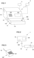
- Fig. 1 shows in a schematic view a cash register system 1 which has a cash register device 10 and a cash drawer 11 arranged on the cash register device 10 with an adjustable drawer 111 and a storage compartment 112 arranged therein for storing cash.
- the cash register device 10 has, for example, a (in Fig. 2 schematically shown) registration device 101 for scanning barcodes of goods, an input device 102 for typing in a product identifier and a display device 103 in the form of a screen for displaying product-related information, an amount to be paid or the like.
- a registration device 101 for scanning barcodes of goods
- an input device 102 for typing in a product identifier
- a display device 103 in the form of a screen for displaying product-related information, an amount to be paid or the like.
- the cash register device 10 has a control device 14 which is designed to control a payment process and also to control the cash drawer 11, in particular to automatically open the drawer 111 of the cash drawer 11.
- a sensor device 13 is provided on the cash drawer 11, which is designed, for example, as a microswitch or microcontact and serves to detect whether the drawer 111 of the cash drawer 11 is in an open state in which access to the storage compartment 112 located in the drawer 11 is possible. or in a closed state in which the drawer 111 is retracted into a housing 110 of the cash drawer 11.
- the cash drawer 11 is preferably designed as a modular unit and its housing 110 is releasably inserted into a receiving slot 100 of the cash register device 10.
- the cash drawer 11 is, as shown schematically in Fig. 2 shown, is connected to the cash register device 10 via an electronic data line 12 and a plug connection 120, for example using an RJ11 or RJ12 plug, and is thus connected to the cash register device 10 for electrical communication.
- Fig. 3 shows a schematic of a plug of the plug connection 120.
- the plug has six pins 121, via which a supply voltage is transmitted to the cash drawer 11, control signals of the control device 14 are passed to the cash drawer 11 and sensor signals of the sensor device 13 can be queried.
- a normal payment transaction using a cash register system 1 in Fig. 1 and 2 The type shown is, for example, as follows.
- the barcodes of a number of goods are read using the registration device 101 and the goods are registered in this way.
- product identifiers can also be entered using the input device 102.
- the cash register device 10 stores the registered goods, adds the individual amounts assigned to the goods to a total amount and, if necessary, outputs product-related information and a total amount via the display device 103.
- a payment process is to be completed and the registered goods are to be paid for, this can be done, for example, by means of a suitable input via the input device 102, whereupon the cash register device 10 displays the final amount via the display device 103 and generates a control signal in the form of a control pulse via the control device 14, which is transmitted to the cash drawer 11 and causes the drawer 111 of the cash drawer 11 to open automatically.
- the drawer 111 is open, cash can then be placed in the storage compartment 112 of the cash drawer 11 and change can be given to a customer.
- an operator closes the drawer 111 manually so that the next payment process, during which goods are again read and registered, can begin.
- the automatic opening of the drawer 111 is effected by a control signal from the control device 14.
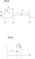
- a control signal P is shown schematically in Fig. 4 together with an opening signal A from the sensor device 13.
- the reference symbol S1 here designates a signal output by the control device 14, while the reference symbol S2 indicates a sensor signal emitted by the sensor device 13.
- the control signal P corresponds to a pulse-shaped increased signal level of the signal S1 from the control device 14, while the opening signal A corresponds to an increased signal level of the signal S2 from the sensor device 13.
- the automatic opening process of the drawer 111 is initiated by means of the control signal P. If the drawer 111 is opened, the sensor device 13 outputs an increased signal level and thus generates the sensor signal A.
- the control device 14 generates the control signal P at a time t1 (reference is made to the rising edge of the control signal P).
- the drawer 111 is opened during a proper opening process, so that the opening signal A is present from time t2 (corresponding to the rising edge of the opening signal A).
- the drawer 111 is closed again, so that the signal level of the signal S2 of the sensor device 13 drops and thus no more opening signal A is emitted.
- the time period T is approximately equal to a reference time period T0 (see Fig. 5 ) so that by comparing the time period T with the predetermined reference time period T0 it can be determined whether an opening operation is carried out correctly or not.
- a measured time period T' as also in Fig. 5 shown, but deviates significantly from the reference time period T0 and in particular lies outside the tolerance range B around the reference time period T0, this may indicate that the sensor device 13 has been manipulated, for example to simulate the closing of the drawer 111 after a payment transaction has taken place. This can be done, for example, by an operator bringing a foreign object, for example a microswitch or microcontact of the sensor device 13, close to and thus activating it, so that the sensor device 13 no longer emits an opening signal A and the control device 14 thus falsely assumes that the drawer 111 has been closed.
- a foreign object for example a microswitch or microcontact of the sensor device 13
- an opening signal A is again present, but this appears at a time t1 that differs from the reference time period T0 or, if necessary, completely independently of a control signal P.
- the reference time period T0 with its tolerance range can also be specified by limits of an acceptable range. For example, a time period T that is within an acceptable range can be considered to be correct, while a time period that is outside the acceptable range indicates a manipulation process.
- the actual time between a control signal P and the start of the opening signal A can, in a real system, be in a range between 15 ms and 100 ms, in particular between 25 ms and 75 ms, e.g. around 50 ms.
- the reference time period T0 can be selected accordingly, and it can be concluded, for example, that a manipulation process has taken place if the time period T is, for example, less than 15 ms, preferably less than 10 ms, and greater than 100 ms, preferably greater than 250 ms.
- a corresponding countermeasure can be initiated by the control device 14.
- the card device 10 can be connected to a monitoring device 2 (see Fig. 1 ) which can be controlled by the control device 14 when a manipulation process is detected in order to record the cash register system 1 and its surroundings if necessary and to record a manipulation process in this way.
- the cash register device 10 can also work together with an alarm system 3 which generates an acoustic alarm or alerts security personnel can raise alarm silently or loudly inside or outside a store.
- control device 14 in cooperation with a cash register software of the cash register device 10, to assign a detected manipulation process to an operator logged on to the cash register device 10 and in this way to log the manipulation process.
- the cash register system 1 can also have a self-learning function.
- the control device 14 can thus detect in a self-learning manner if the time required to open the cash drawer 1 during a normal opening process changes, for example due to age-related wear and tear and due to age-related stiffness.
- the control device 14 adapts the reference time period T0 or a permissible tolerance range B around the reference time period T0 in a self-learning manner, e.g. if it recognizes that the time required to open the cash drawer increases over a period of time during normal, normal opening processes, so that a false alarm due to wear or age-related stiffness can be avoided if possible.
- the cash drawer can also be designed in a completely different way, for example with a flap that closes a storage compartment or the like.
- the sensor device can in principle be designed in any way and is not necessarily implemented by a microswitch or microcontact.
- the drive for opening the cash drawer is basically arbitrary and can in particular be designed as an electric motor or mechanically using a mechanical energy storage device, e.g. a spring or the like.
Landscapes
- Physics & Mathematics (AREA)
- General Physics & Mathematics (AREA)
- Business, Economics & Management (AREA)
- Engineering & Computer Science (AREA)
- Accounting & Taxation (AREA)
- Computer Security & Cryptography (AREA)
- Finance (AREA)
- Strategic Management (AREA)
- General Business, Economics & Management (AREA)
- Theoretical Computer Science (AREA)
- Cash Registers Or Receiving Machines (AREA)
Claims (8)
- Système de caisse (1) comprenant- un dispositif de caisse (10) destiné à réaliser une opération de paiement,- un tiroir de caisse (11), qui possède un compartiment de conservation (112) destiné à conserver de l'argent, le compartiment de conservation (112) étant ouvert pour un accès dans un état ouvert du tiroir de caisse (11) et le compartiment de conservation (112) étant fermé dans un état fermé du tiroir de caisse (11),- un dispositif de commande (14) destiné à commander le tiroir de caisse (11), le dispositif de commande (14) étant configuré pour générer un signal de commande (P) servant à ouvrir le tiroir de caisse (11), et- un dispositif capteur (13) destiné à générer un signal d'ouverture (A), lequel indique si le tiroir de caisse (11) se trouve dans son état ouvert,caractérisé en ce
que le dispositif de commande (14) est configuré pour évaluer si un signal de commande (P) a précédé ou non un signal d'ouverture (A) avec un intervalle de temps (T0) prédéterminé, afin de reconnaître, à l'aide de l'évaluation, une opération de manipulation lors de l'ouverture et/ou de la fermeture du tiroir de caisse (11), le dispositif de commande (14) étant configuré pour détecter une durée (T) entre un front montant d'un signal d'ouverture (A) généré par le dispositif capteur (13) et un front montant d'un signal de commande (P) précédent destiné à l'ouverture du tiroir de caisse (11) et le comparer avec une durée de référence (T0) prédéterminée en vue de détecter une opération de manipulation, le dispositif de commande (14) étant configuré à autoapprentissage pour signaler une opération de manipulation lorsqu'une durée (T) détectée entre un signal d'ouverture (A) généré par le dispositif capteur (13) et un signal de commande (P) précédent destiné à l'ouverture du tiroir de caisse (11) se trouve en dehors d'une plage de tolérance (B) admissible autour de la durée de référence (T0), et pour adapter la durée de référence (T0) et/ou une plage de tolérance (B) lorsqu'il reconnaît, sur une période donnée, une modification dans une opération d'ouverture du tiroir de caisse (1) conforme à l'usage prévu. - Système de caisse (1) selon la revendication 1, caractérisé en ce que le dispositif de commande (14) est configuré pour signaler une opération de manipulation lorsqu'aucun signal de commande (P) n'a précédé directement un signal d'ouverture (A).
- Système de caisse (1) selon la revendication 1 ou 2, caractérisé en ce que le tiroir de caisse (11) peut être retiré du dispositif de caisse (10).
- Système de caisse (1) selon l'une des revendications précédentes, caractérisé en ce que le tiroir de caisse (11) est relié au dispositif de caisse (10) par le biais d'une ligne de données électrique (12).
- Système de caisse (1) selon la revendication 5, caractérisé en ce que le dispositif de commande (14) est configuré pour, par le biais de la ligne de données électrique (12), envoyer un signal de commande (P) au tiroir de caisse (11) et interroger un signal d'ouverture (A) .
- Système de caisse (1) selon l'une des revendications précédentes, caractérisé en ce que le dispositif de commande (14) est configuré pour interagir avec un dispositif de surveillance (2) et, en cas de reconnaissance d'une opération de manipulation, commander le dispositif de surveillance (2) en vue d'initier une opération de surveillance.
- Système de caisse (1) selon l'une des revendications précédentes, caractérisé en ce que le dispositif de commande (14) est configuré pour, en cas de reconnaissance d'une opération de manipulation, commander un système d'alarme (3) en vue de générer une alarme.
- Procédé pour faire fonctionner un système de caisse (1), qui comporte- un dispositif de caisse (10) destiné à réaliser une opération de paiement et- un tiroir de caisse (11), qui possède un compartiment de conservation (112) destiné à conserver de l'argent, le compartiment de conservation (112) étant ouvert pour un accès dans un état ouvert du tiroir de caisse (11) et le compartiment de conservation (112) étant fermé dans un état fermé du tiroir de caisse (11), un dispositif de commande (14) générant un signal de commande (P) servant à ouvrir le tiroir de caisse (11) et un dispositif capteur (13) générant un signal d'ouverture (A), lequel indique si le tiroir de caisse (11) se trouve dans son état ouvert,caractérisé en ce
que le dispositif de commande (14) évalue si un signal de commande (P) a précédé ou non un signal d'ouverture (A) avec un intervalle de temps (T0) prédéterminé, afin de reconnaître, à l'aide de l'évaluation, une opération de manipulation lors de l'ouverture et/ou de la fermeture du tiroir de caisse (11), le dispositif de commande (14) détectant une durée (T) entre un front montant d'un signal d'ouverture (A) généré par le dispositif capteur (13) et un front montant d'un signal de commande (P) précédent destiné à l'ouverture du tiroir de caisse (11) et le comparant avec une durée de référence (T0) prédéterminée en vue de détecter une opération de manipulation, le dispositif de commande (14) signalant une opération de manipulation lorsqu'une durée (T) détectée entre un signal d'ouverture (A) généré par le dispositif capteur (13) et un signal de commande (P) précédent destiné à l'ouverture du tiroir de caisse (11) se trouve en dehors d'une plage de tolérance (B) admissible autour de la durée de référence (T0) et le dispositif de commande étant configuré à autoapprentissage pour adapter la durée de référence (T0) et/ou une plage de tolérance (B) lorsqu'il reconnaît, sur une période donnée, une modification dans une opération d'ouverture du tiroir de caisse (1) conforme à l'usage prévu.
Priority Applications (3)
| Application Number | Priority Date | Filing Date | Title |
|---|---|---|---|
| EP13173379.2A EP2816537B1 (fr) | 2013-06-21 | 2013-06-24 | Système de caisse et procédé de fonctionnement d'un système de caisse |
| US14/311,100 US9715794B2 (en) | 2013-06-21 | 2014-06-20 | POS system and method for operating a POS system |
| CN201410283327.4A CN104240410B (zh) | 2013-06-21 | 2014-06-23 | 结算系统和用于运行结算系统的方法 |
Applications Claiming Priority (2)
| Application Number | Priority Date | Filing Date | Title |
|---|---|---|---|
| EP13173301 | 2013-06-21 | ||
| EP13173379.2A EP2816537B1 (fr) | 2013-06-21 | 2013-06-24 | Système de caisse et procédé de fonctionnement d'un système de caisse |
Publications (2)
| Publication Number | Publication Date |
|---|---|
| EP2816537A1 EP2816537A1 (fr) | 2014-12-24 |
| EP2816537B1 true EP2816537B1 (fr) | 2024-10-09 |
Family
ID=48692295
Family Applications (1)
| Application Number | Title | Priority Date | Filing Date |
|---|---|---|---|
| EP13173379.2A Active EP2816537B1 (fr) | 2013-06-21 | 2013-06-24 | Système de caisse et procédé de fonctionnement d'un système de caisse |
Country Status (4)
| Country | Link |
|---|---|
| US (1) | US9715794B2 (fr) |
| EP (1) | EP2816537B1 (fr) |
| CN (1) | CN104240410B (fr) |
| HK (1) | HK1204129A1 (fr) |
Families Citing this family (4)
| Publication number | Priority date | Publication date | Assignee | Title |
|---|---|---|---|---|
| EP3580663A4 (fr) * | 2017-02-07 | 2020-10-14 | Hewlett-Packard Development Company, L.P. | Détermination d'accès à un tiroir-caisse |
| DE102019117963A1 (de) * | 2019-07-03 | 2021-01-07 | Wincor Nixdorf International Gmbh | Geldlade für ein elektronisches kassensystem, kassensystem und verfahren zum betreiben einer geldlade |
| JP7691810B2 (ja) * | 2020-02-25 | 2025-06-12 | 東芝テック株式会社 | 商品販売データ処理装置およびプログラム |
| JP7633489B2 (ja) * | 2020-12-28 | 2025-02-20 | スター精密株式会社 | ドロワ制御装置、ドロワ制御方法およびドロワ制御システム |
Citations (3)
| Publication number | Priority date | Publication date | Assignee | Title |
|---|---|---|---|---|
| US4595985A (en) * | 1982-08-25 | 1986-06-17 | Omron Tateisi Electronics Co. | Electronic cash register |
| DE19839977A1 (de) * | 1998-09-02 | 2000-03-09 | Siemens Nixdorf Inf Syst | Geldkassettenanordnung |
| US20150034398A1 (en) * | 2012-03-23 | 2015-02-05 | Peter G. Charij | Cash registers and other cash holding devices |
Family Cites Families (10)
| Publication number | Priority date | Publication date | Assignee | Title |
|---|---|---|---|---|
| JPS57100556A (en) * | 1980-12-13 | 1982-06-22 | Casio Comput Co Ltd | Detecting system for drawer opening time |
| JPH079678B2 (ja) | 1983-03-01 | 1995-02-01 | オムロン株式会社 | 電子式キヤツシユ・レジスタ |
| JPH09171590A (ja) * | 1995-12-20 | 1997-06-30 | Fujitsu General Ltd | 電子キャッシュレジスタ |
| JPH09319963A (ja) * | 1996-05-31 | 1997-12-12 | Tec Corp | 商品販売登録データ処理装置 |
| JPH10143761A (ja) * | 1996-11-15 | 1998-05-29 | Tec Corp | 商品販売登録データ処理装置 |
| JP2001126143A (ja) * | 1999-10-22 | 2001-05-11 | Teraoka Seiko Co Ltd | キャッシュレジスタ |
| JP4369502B2 (ja) * | 2007-07-26 | 2009-11-25 | 東芝テック株式会社 | 商品販売データ処理装置 |
| US8224701B2 (en) * | 2008-06-02 | 2012-07-17 | Universal Scientific Industrial (Shanghai) Co., Ltd. | Detecting device for a cash drawer and a point of sales system |
| JP5311239B2 (ja) * | 2011-06-17 | 2013-10-09 | カシオ計算機株式会社 | 売上データ処理装置及びプログラム |
| US20140088760A1 (en) * | 2012-09-25 | 2014-03-27 | Hewlett-Packard Development Company, L.P. | Computer connected cash drawer status and control |
-
2013
- 2013-06-24 EP EP13173379.2A patent/EP2816537B1/fr active Active
-
2014
- 2014-06-20 US US14/311,100 patent/US9715794B2/en active Active
- 2014-06-23 CN CN201410283327.4A patent/CN104240410B/zh active Active
-
2015
- 2015-05-06 HK HK15104303.7A patent/HK1204129A1/xx unknown
Patent Citations (3)
| Publication number | Priority date | Publication date | Assignee | Title |
|---|---|---|---|---|
| US4595985A (en) * | 1982-08-25 | 1986-06-17 | Omron Tateisi Electronics Co. | Electronic cash register |
| DE19839977A1 (de) * | 1998-09-02 | 2000-03-09 | Siemens Nixdorf Inf Syst | Geldkassettenanordnung |
| US20150034398A1 (en) * | 2012-03-23 | 2015-02-05 | Peter G. Charij | Cash registers and other cash holding devices |
Non-Patent Citations (2)
| Title |
|---|
| ANONYMOUS: "Messabweichung - Wikipedia", 27 March 2013 (2013-03-27), XP055710265, Retrieved from the Internet <URL:https://de.wikipedia.org/w/index.php?title=Messabweichung&oldid=115959867> [retrieved on 20200630] * |
| H UNBEHAUEN: "Regelungs-und Steuerungstechnik / Regelungstechnik, 13 Weitere Reglerentwurfsverfahren", H�TTE - DAS INGENIEURWISSEN, 7 December 2012 (2012-12-07), pages 1443 - 1449, XP055710553, ISBN: 978-3-642-22850-6, Retrieved from the Internet <URL:http://ebookcentral.proquest.com/lib/epo-ebooks/detail.action?docID=994223> [retrieved on 20200701] * |
Also Published As
| Publication number | Publication date |
|---|---|
| HK1204129A1 (en) | 2015-11-06 |
| EP2816537A1 (fr) | 2014-12-24 |
| CN104240410A (zh) | 2014-12-24 |
| US9715794B2 (en) | 2017-07-25 |
| CN104240410B (zh) | 2018-12-21 |
| US20140379501A1 (en) | 2014-12-25 |
Similar Documents
| Publication | Publication Date | Title |
|---|---|---|
| DE3205620C2 (fr) | ||
| DE2760486C2 (fr) | ||
| DE102004035224B4 (de) | Selbstbedienungsgerät mit Manipulationserkennung | |
| EP2816537B1 (fr) | Système de caisse et procédé de fonctionnement d'un système de caisse | |
| EP2286390B1 (fr) | Système de reconnaissance de manipulation pour des coffres amovibles utilisés dans des guichets automatiques bancaires | |
| DE102009019708B4 (de) | Vorrichtung zum Schutz einer Kartenleseeinrichtung, Automat hiermit | |
| WO2009126984A1 (fr) | Procédé d’utilisation d’un équipement technique commandable électriquement et dispositif de commande correspondant | |
| EP0007579A1 (fr) | Circuit de surveillance de l'état de systèmes de signalisation, spécialement de systèmes lumineux de signalisation de circulation routière | |
| DE60108459T2 (de) | Türüberwachung in einem Spielautomat | |
| DE2627981B2 (de) | Identifizierungssystem mittels Fingerabdrucken | |
| EP3113122B1 (fr) | Systeme de reprise de produits jetables a valoriser et dispositif et procede de reconnaissance de manipulation de ces derniers | |
| DE102011010737A1 (de) | Verfahren zur Verbesserung des Manipulationsschutzes von Geldautomaten, sowie Geldautomat zur Durchführung des Verfahrens | |
| DE102013110385A1 (de) | Distributionsautomat für die Verteilung, Übergabe, temporäre Aufbewahrung oder den automatisierten Verkauf von Gegenständen | |
| EP3347880B1 (fr) | Procédé et dispositif de détermination de l'intégrité d'un dispositif lecteur de carte et terminal de distribution automatique en étant équipé | |
| EP2603905B1 (fr) | Procédé et dispositif de détection et de vérification de tentatives de manipulation sur un terminal de distribution automatique | |
| EP2722788A1 (fr) | Dispositif de lecture d'une carte à puce et procédé de détection d'un module de skimming | |
| EP1839276B1 (fr) | Systeme et procede pour enregistrer l'ouverture de verrous d'espaces a securiser | |
| EP1389257B1 (fr) | Systeme de securite pour coffrets | |
| DE112019001977T5 (de) | Steuerungseinrichtung für ein Öffnungs- und Schließelement und Steuerungsverfahren für ein Öffnungs- und Schließelement | |
| EP2722784B1 (fr) | Dispositif électronique | |
| DE69706399T2 (de) | Zustandssensor für schalter | |
| WO2008034653A1 (fr) | Procédé et arrangement pour constater une manipulation non autorisée d'un équipement électrique | |
| DE102020107110A1 (de) | Robotersteuersystem | |
| EP1760558B2 (fr) | Dispositif et procédé destinés à examiner la sécurité d'un dispositif technique | |
| EP3065112A1 (fr) | Système de reprise d'articles consignés doté d'une unité de détection par le son destinée à reconnaître la destruction de l'article à usage unique |
Legal Events
| Date | Code | Title | Description |
|---|---|---|---|
| PUAI | Public reference made under article 153(3) epc to a published international application that has entered the european phase |
Free format text: ORIGINAL CODE: 0009012 |
|
| 17P | Request for examination filed |
Effective date: 20130624 |
|
| AK | Designated contracting states |
Kind code of ref document: A1 Designated state(s): AL AT BE BG CH CY CZ DE DK EE ES FI FR GB GR HR HU IE IS IT LI LT LU LV MC MK MT NL NO PL PT RO RS SE SI SK SM TR |
|
| AX | Request for extension of the european patent |
Extension state: BA ME |
|
| R17P | Request for examination filed (corrected) |
Effective date: 20150518 |
|
| RBV | Designated contracting states (corrected) |
Designated state(s): AL AT BE BG CH CY CZ DE DK EE ES FI FR GB GR HR HU IE IS IT LI LT LU LV MC MK MT NL NO PL PT RO RS SE SI SK SM TR |
|
| REG | Reference to a national code |
Ref country code: HK Ref legal event code: DE Ref document number: 1204129 Country of ref document: HK |
|
| STAA | Information on the status of an ep patent application or granted ep patent |
Free format text: STATUS: EXAMINATION IS IN PROGRESS |
|
| 17Q | First examination report despatched |
Effective date: 20180122 |
|
| APBK | Appeal reference recorded |
Free format text: ORIGINAL CODE: EPIDOSNREFNE |
|
| APBN | Date of receipt of notice of appeal recorded |
Free format text: ORIGINAL CODE: EPIDOSNNOA2E |
|
| APBR | Date of receipt of statement of grounds of appeal recorded |
Free format text: ORIGINAL CODE: EPIDOSNNOA3E |
|
| APAF | Appeal reference modified |
Free format text: ORIGINAL CODE: EPIDOSCREFNE |
|
| REG | Reference to a national code |
Ref country code: HK Ref legal event code: WD Ref document number: 1204129 Country of ref document: HK |
|
| RAP1 | Party data changed (applicant data changed or rights of an application transferred) |
Owner name: DIEBOLD NIXDORF SYSTEMS GMBH |
|
| APBT | Appeal procedure closed |
Free format text: ORIGINAL CODE: EPIDOSNNOA9E |
|
| GRAP | Despatch of communication of intention to grant a patent |
Free format text: ORIGINAL CODE: EPIDOSNIGR1 |
|
| STAA | Information on the status of an ep patent application or granted ep patent |
Free format text: STATUS: GRANT OF PATENT IS INTENDED |
|
| INTG | Intention to grant announced |
Effective date: 20240503 |
|
| GRAS | Grant fee paid |
Free format text: ORIGINAL CODE: EPIDOSNIGR3 |
|
| GRAA | (expected) grant |
Free format text: ORIGINAL CODE: 0009210 |
|
| STAA | Information on the status of an ep patent application or granted ep patent |
Free format text: STATUS: THE PATENT HAS BEEN GRANTED |
|
| AK | Designated contracting states |
Kind code of ref document: B1 Designated state(s): AL AT BE BG CH CY CZ DE DK EE ES FI FR GB GR HR HU IE IS IT LI LT LU LV MC MK MT NL NO PL PT RO RS SE SI SK SM TR |
|
| REG | Reference to a national code |
Ref country code: GB Ref legal event code: FG4D Free format text: NOT ENGLISH |
|
| REG | Reference to a national code |
Ref country code: CH Ref legal event code: EP |
|
| REG | Reference to a national code |
Ref country code: DE Ref legal event code: R096 Ref document number: 502013016545 Country of ref document: DE |
|
| REG | Reference to a national code |
Ref country code: IE Ref legal event code: FG4D Free format text: LANGUAGE OF EP DOCUMENT: GERMAN |
|
| REG | Reference to a national code |
Ref country code: LT Ref legal event code: MG9D |
|
| REG | Reference to a national code |
Ref country code: NL Ref legal event code: MP Effective date: 20241009 |
|
| PG25 | Lapsed in a contracting state [announced via postgrant information from national office to epo] |
Ref country code: NL Free format text: LAPSE BECAUSE OF FAILURE TO SUBMIT A TRANSLATION OF THE DESCRIPTION OR TO PAY THE FEE WITHIN THE PRESCRIBED TIME-LIMIT Effective date: 20241009 |
|
| PG25 | Lapsed in a contracting state [announced via postgrant information from national office to epo] |
Ref country code: NL Free format text: LAPSE BECAUSE OF FAILURE TO SUBMIT A TRANSLATION OF THE DESCRIPTION OR TO PAY THE FEE WITHIN THE PRESCRIBED TIME-LIMIT Effective date: 20241009 |
|
| PG25 | Lapsed in a contracting state [announced via postgrant information from national office to epo] |
Ref country code: PT Free format text: LAPSE BECAUSE OF FAILURE TO SUBMIT A TRANSLATION OF THE DESCRIPTION OR TO PAY THE FEE WITHIN THE PRESCRIBED TIME-LIMIT Effective date: 20250210 Ref country code: HR Free format text: LAPSE BECAUSE OF FAILURE TO SUBMIT A TRANSLATION OF THE DESCRIPTION OR TO PAY THE FEE WITHIN THE PRESCRIBED TIME-LIMIT Effective date: 20241009 Ref country code: IS Free format text: LAPSE BECAUSE OF FAILURE TO SUBMIT A TRANSLATION OF THE DESCRIPTION OR TO PAY THE FEE WITHIN THE PRESCRIBED TIME-LIMIT Effective date: 20250209 |
|
| PG25 | Lapsed in a contracting state [announced via postgrant information from national office to epo] |
Ref country code: FI Free format text: LAPSE BECAUSE OF FAILURE TO SUBMIT A TRANSLATION OF THE DESCRIPTION OR TO PAY THE FEE WITHIN THE PRESCRIBED TIME-LIMIT Effective date: 20241009 |
|
| PG25 | Lapsed in a contracting state [announced via postgrant information from national office to epo] |
Ref country code: BG Free format text: LAPSE BECAUSE OF FAILURE TO SUBMIT A TRANSLATION OF THE DESCRIPTION OR TO PAY THE FEE WITHIN THE PRESCRIBED TIME-LIMIT Effective date: 20241009 |
|
| PG25 | Lapsed in a contracting state [announced via postgrant information from national office to epo] |
Ref country code: ES Free format text: LAPSE BECAUSE OF FAILURE TO SUBMIT A TRANSLATION OF THE DESCRIPTION OR TO PAY THE FEE WITHIN THE PRESCRIBED TIME-LIMIT Effective date: 20241009 |
|
| PG25 | Lapsed in a contracting state [announced via postgrant information from national office to epo] |
Ref country code: NO Free format text: LAPSE BECAUSE OF FAILURE TO SUBMIT A TRANSLATION OF THE DESCRIPTION OR TO PAY THE FEE WITHIN THE PRESCRIBED TIME-LIMIT Effective date: 20250109 |
|
| PG25 | Lapsed in a contracting state [announced via postgrant information from national office to epo] |
Ref country code: LV Free format text: LAPSE BECAUSE OF FAILURE TO SUBMIT A TRANSLATION OF THE DESCRIPTION OR TO PAY THE FEE WITHIN THE PRESCRIBED TIME-LIMIT Effective date: 20241009 Ref country code: GR Free format text: LAPSE BECAUSE OF FAILURE TO SUBMIT A TRANSLATION OF THE DESCRIPTION OR TO PAY THE FEE WITHIN THE PRESCRIBED TIME-LIMIT Effective date: 20250110 |
|
| PG25 | Lapsed in a contracting state [announced via postgrant information from national office to epo] |
Ref country code: PL Free format text: LAPSE BECAUSE OF FAILURE TO SUBMIT A TRANSLATION OF THE DESCRIPTION OR TO PAY THE FEE WITHIN THE PRESCRIBED TIME-LIMIT Effective date: 20241009 |
|
| PG25 | Lapsed in a contracting state [announced via postgrant information from national office to epo] |
Ref country code: RS Free format text: LAPSE BECAUSE OF FAILURE TO SUBMIT A TRANSLATION OF THE DESCRIPTION OR TO PAY THE FEE WITHIN THE PRESCRIBED TIME-LIMIT Effective date: 20250109 |
|
| PG25 | Lapsed in a contracting state [announced via postgrant information from national office to epo] |
Ref country code: SM Free format text: LAPSE BECAUSE OF FAILURE TO SUBMIT A TRANSLATION OF THE DESCRIPTION OR TO PAY THE FEE WITHIN THE PRESCRIBED TIME-LIMIT Effective date: 20241009 |
|
| PGFP | Annual fee paid to national office [announced via postgrant information from national office to epo] |
Ref country code: DE Payment date: 20250520 Year of fee payment: 13 |
|
| PG25 | Lapsed in a contracting state [announced via postgrant information from national office to epo] |
Ref country code: DK Free format text: LAPSE BECAUSE OF FAILURE TO SUBMIT A TRANSLATION OF THE DESCRIPTION OR TO PAY THE FEE WITHIN THE PRESCRIBED TIME-LIMIT Effective date: 20241009 |
|
| PGFP | Annual fee paid to national office [announced via postgrant information from national office to epo] |
Ref country code: GB Payment date: 20250520 Year of fee payment: 13 |
|
| REG | Reference to a national code |
Ref country code: DE Ref legal event code: R097 Ref document number: 502013016545 Country of ref document: DE |
|
| PG25 | Lapsed in a contracting state [announced via postgrant information from national office to epo] |
Ref country code: EE Free format text: LAPSE BECAUSE OF FAILURE TO SUBMIT A TRANSLATION OF THE DESCRIPTION OR TO PAY THE FEE WITHIN THE PRESCRIBED TIME-LIMIT Effective date: 20241009 |
|
| PGFP | Annual fee paid to national office [announced via postgrant information from national office to epo] |
Ref country code: FR Payment date: 20250520 Year of fee payment: 13 |
|
| PG25 | Lapsed in a contracting state [announced via postgrant information from national office to epo] |
Ref country code: RO Free format text: LAPSE BECAUSE OF FAILURE TO SUBMIT A TRANSLATION OF THE DESCRIPTION OR TO PAY THE FEE WITHIN THE PRESCRIBED TIME-LIMIT Effective date: 20241009 |
|
| PG25 | Lapsed in a contracting state [announced via postgrant information from national office to epo] |
Ref country code: SK Free format text: LAPSE BECAUSE OF FAILURE TO SUBMIT A TRANSLATION OF THE DESCRIPTION OR TO PAY THE FEE WITHIN THE PRESCRIBED TIME-LIMIT Effective date: 20241009 |
|
| PG25 | Lapsed in a contracting state [announced via postgrant information from national office to epo] |
Ref country code: CZ Free format text: LAPSE BECAUSE OF FAILURE TO SUBMIT A TRANSLATION OF THE DESCRIPTION OR TO PAY THE FEE WITHIN THE PRESCRIBED TIME-LIMIT Effective date: 20241009 |
|
| PG25 | Lapsed in a contracting state [announced via postgrant information from national office to epo] |
Ref country code: IT Free format text: LAPSE BECAUSE OF FAILURE TO SUBMIT A TRANSLATION OF THE DESCRIPTION OR TO PAY THE FEE WITHIN THE PRESCRIBED TIME-LIMIT Effective date: 20241009 |
|
| PLBE | No opposition filed within time limit |
Free format text: ORIGINAL CODE: 0009261 |
|
| STAA | Information on the status of an ep patent application or granted ep patent |
Free format text: STATUS: NO OPPOSITION FILED WITHIN TIME LIMIT |
|
| PG25 | Lapsed in a contracting state [announced via postgrant information from national office to epo] |
Ref country code: SE Free format text: LAPSE BECAUSE OF FAILURE TO SUBMIT A TRANSLATION OF THE DESCRIPTION OR TO PAY THE FEE WITHIN THE PRESCRIBED TIME-LIMIT Effective date: 20241009 |
|
| 26N | No opposition filed |
Effective date: 20250710 |
|
| REG | Reference to a national code |
Ref country code: CH Ref legal event code: H13 Free format text: ST27 STATUS EVENT CODE: U-0-0-H10-H13 (AS PROVIDED BY THE NATIONAL OFFICE) Effective date: 20260127 |
|
| PG25 | Lapsed in a contracting state [announced via postgrant information from national office to epo] |
Ref country code: MC Free format text: LAPSE BECAUSE OF FAILURE TO SUBMIT A TRANSLATION OF THE DESCRIPTION OR TO PAY THE FEE WITHIN THE PRESCRIBED TIME-LIMIT Effective date: 20241009 |
|
| PG25 | Lapsed in a contracting state [announced via postgrant information from national office to epo] |
Ref country code: LU Free format text: LAPSE BECAUSE OF NON-PAYMENT OF DUE FEES Effective date: 20250624 |
|
| REG | Reference to a national code |
Ref country code: BE Ref legal event code: MM Effective date: 20250630 |
|
| PG25 | Lapsed in a contracting state [announced via postgrant information from national office to epo] |
Ref country code: IE Free format text: LAPSE BECAUSE OF NON-PAYMENT OF DUE FEES Effective date: 20250624 |
|
| PG25 | Lapsed in a contracting state [announced via postgrant information from national office to epo] |
Ref country code: BE Free format text: LAPSE BECAUSE OF NON-PAYMENT OF DUE FEES Effective date: 20250630 |
|
| PG25 | Lapsed in a contracting state [announced via postgrant information from national office to epo] |
Ref country code: CH Free format text: LAPSE BECAUSE OF NON-PAYMENT OF DUE FEES Effective date: 20250630 |