EP2845733A1 - Dispositif de formation d'image - Google Patents
Dispositif de formation d'image Download PDFInfo
- Publication number
- EP2845733A1 EP2845733A1 EP13784124.3A EP13784124A EP2845733A1 EP 2845733 A1 EP2845733 A1 EP 2845733A1 EP 13784124 A EP13784124 A EP 13784124A EP 2845733 A1 EP2845733 A1 EP 2845733A1
- Authority
- EP
- European Patent Office
- Prior art keywords
- image formation
- recording medium
- drum
- ink
- formation drum
- Prior art date
- Legal status (The legal status is an assumption and is not a legal conclusion. Google has not performed a legal analysis and makes no representation as to the accuracy of the status listed.)
- Granted
Links
Images



Classifications
-
- B—PERFORMING OPERATIONS; TRANSPORTING
- B41—PRINTING; LINING MACHINES; TYPEWRITERS; STAMPS
- B41J—TYPEWRITERS; SELECTIVE PRINTING MECHANISMS, i.e. MECHANISMS PRINTING OTHERWISE THAN FROM A FORME; CORRECTION OF TYPOGRAPHICAL ERRORS
- B41J11/00—Devices or arrangements of selective printing mechanisms, e.g. ink-jet printers or thermal printers, for supporting or handling copy material in sheet or web form
- B41J11/0015—Devices or arrangements of selective printing mechanisms, e.g. ink-jet printers or thermal printers, for supporting or handling copy material in sheet or web form for treating before, during or after printing or for uniform coating or laminating the copy material before or after printing
- B41J11/002—Curing or drying the ink on the copy materials, e.g. by heating or irradiating
- B41J11/0021—Curing or drying the ink on the copy materials, e.g. by heating or irradiating using irradiation
- B41J11/00214—Curing or drying the ink on the copy materials, e.g. by heating or irradiating using irradiation using UV radiation
-
- B—PERFORMING OPERATIONS; TRANSPORTING
- B41—PRINTING; LINING MACHINES; TYPEWRITERS; STAMPS
- B41J—TYPEWRITERS; SELECTIVE PRINTING MECHANISMS, i.e. MECHANISMS PRINTING OTHERWISE THAN FROM A FORME; CORRECTION OF TYPOGRAPHICAL ERRORS
- B41J11/00—Devices or arrangements of selective printing mechanisms, e.g. ink-jet printers or thermal printers, for supporting or handling copy material in sheet or web form
- B41J11/0015—Devices or arrangements of selective printing mechanisms, e.g. ink-jet printers or thermal printers, for supporting or handling copy material in sheet or web form for treating before, during or after printing or for uniform coating or laminating the copy material before or after printing
- B41J11/002—Curing or drying the ink on the copy materials, e.g. by heating or irradiating
- B41J11/0022—Curing or drying the ink on the copy materials, e.g. by heating or irradiating using convection means, e.g. by using a fan for blowing or sucking air
-
- B—PERFORMING OPERATIONS; TRANSPORTING
- B41—PRINTING; LINING MACHINES; TYPEWRITERS; STAMPS
- B41J—TYPEWRITERS; SELECTIVE PRINTING MECHANISMS, i.e. MECHANISMS PRINTING OTHERWISE THAN FROM A FORME; CORRECTION OF TYPOGRAPHICAL ERRORS
- B41J11/00—Devices or arrangements of selective printing mechanisms, e.g. ink-jet printers or thermal printers, for supporting or handling copy material in sheet or web form
- B41J11/0015—Devices or arrangements of selective printing mechanisms, e.g. ink-jet printers or thermal printers, for supporting or handling copy material in sheet or web form for treating before, during or after printing or for uniform coating or laminating the copy material before or after printing
- B41J11/002—Curing or drying the ink on the copy materials, e.g. by heating or irradiating
- B41J11/0024—Curing or drying the ink on the copy materials, e.g. by heating or irradiating using conduction means, e.g. by using a heated platen
-
- B—PERFORMING OPERATIONS; TRANSPORTING
- B41—PRINTING; LINING MACHINES; TYPEWRITERS; STAMPS
- B41J—TYPEWRITERS; SELECTIVE PRINTING MECHANISMS, i.e. MECHANISMS PRINTING OTHERWISE THAN FROM A FORME; CORRECTION OF TYPOGRAPHICAL ERRORS
- B41J11/00—Devices or arrangements of selective printing mechanisms, e.g. ink-jet printers or thermal printers, for supporting or handling copy material in sheet or web form
- B41J11/007—Conveyor belts or like feeding devices
-
- B—PERFORMING OPERATIONS; TRANSPORTING
- B41—PRINTING; LINING MACHINES; TYPEWRITERS; STAMPS
- B41J—TYPEWRITERS; SELECTIVE PRINTING MECHANISMS, i.e. MECHANISMS PRINTING OTHERWISE THAN FROM A FORME; CORRECTION OF TYPOGRAPHICAL ERRORS
- B41J13/00—Devices or arrangements of selective printing mechanisms, e.g. ink-jet printers or thermal printers, specially adapted for supporting or handling copy material in short lengths, e.g. sheets
- B41J13/10—Sheet holders, retainers, movable guides, or stationary guides
- B41J13/22—Clamps or grippers
- B41J13/223—Clamps or grippers on rotatable drums
-
- B—PERFORMING OPERATIONS; TRANSPORTING
- B41—PRINTING; LINING MACHINES; TYPEWRITERS; STAMPS
- B41J—TYPEWRITERS; SELECTIVE PRINTING MECHANISMS, i.e. MECHANISMS PRINTING OTHERWISE THAN FROM A FORME; CORRECTION OF TYPOGRAPHICAL ERRORS
- B41J2/00—Typewriters or selective printing mechanisms characterised by the printing or marking process for which they are designed
- B41J2/005—Typewriters or selective printing mechanisms characterised by the printing or marking process for which they are designed characterised by bringing liquid or particles selectively into contact with a printing material
- B41J2/01—Ink jet
- B41J2/135—Nozzles
- B41J2/165—Prevention or detection of nozzle clogging, e.g. cleaning, capping or moistening for nozzles
- B41J2/16517—Cleaning of print head nozzles
-
- B—PERFORMING OPERATIONS; TRANSPORTING
- B41—PRINTING; LINING MACHINES; TYPEWRITERS; STAMPS
- B41J—TYPEWRITERS; SELECTIVE PRINTING MECHANISMS, i.e. MECHANISMS PRINTING OTHERWISE THAN FROM A FORME; CORRECTION OF TYPOGRAPHICAL ERRORS
- B41J2/00—Typewriters or selective printing mechanisms characterised by the printing or marking process for which they are designed
- B41J2/005—Typewriters or selective printing mechanisms characterised by the printing or marking process for which they are designed characterised by bringing liquid or particles selectively into contact with a printing material
- B41J2/01—Ink jet
- B41J2/135—Nozzles
- B41J2/165—Prevention or detection of nozzle clogging, e.g. cleaning, capping or moistening for nozzles
- B41J2/16585—Prevention or detection of nozzle clogging, e.g. cleaning, capping or moistening for nozzles for paper-width or non-reciprocating print heads
- B41J2/16588—Print heads movable towards the cleaning unit
-
- B—PERFORMING OPERATIONS; TRANSPORTING
- B41—PRINTING; LINING MACHINES; TYPEWRITERS; STAMPS
- B41J—TYPEWRITERS; SELECTIVE PRINTING MECHANISMS, i.e. MECHANISMS PRINTING OTHERWISE THAN FROM A FORME; CORRECTION OF TYPOGRAPHICAL ERRORS
- B41J2/00—Typewriters or selective printing mechanisms characterised by the printing or marking process for which they are designed
- B41J2/005—Typewriters or selective printing mechanisms characterised by the printing or marking process for which they are designed characterised by bringing liquid or particles selectively into contact with a printing material
- B41J2/01—Ink jet
- B41J2/17—Ink jet characterised by ink handling
- B41J2/175—Ink supply systems ; Circuit parts therefor
- B41J2/17593—Supplying ink in a solid state
-
- B—PERFORMING OPERATIONS; TRANSPORTING
- B41—PRINTING; LINING MACHINES; TYPEWRITERS; STAMPS
- B41J—TYPEWRITERS; SELECTIVE PRINTING MECHANISMS, i.e. MECHANISMS PRINTING OTHERWISE THAN FROM A FORME; CORRECTION OF TYPOGRAPHICAL ERRORS
- B41J25/00—Actions or mechanisms not otherwise provided for
- B41J25/001—Mechanisms for bodily moving print heads or carriages parallel to the paper surface
-
- B—PERFORMING OPERATIONS; TRANSPORTING
- B41—PRINTING; LINING MACHINES; TYPEWRITERS; STAMPS
- B41J—TYPEWRITERS; SELECTIVE PRINTING MECHANISMS, i.e. MECHANISMS PRINTING OTHERWISE THAN FROM A FORME; CORRECTION OF TYPOGRAPHICAL ERRORS
- B41J3/00—Typewriters or selective printing or marking mechanisms characterised by the purpose for which they are constructed
- B41J3/60—Typewriters or selective printing or marking mechanisms characterised by the purpose for which they are constructed for printing on both faces of the printing material
-
- B—PERFORMING OPERATIONS; TRANSPORTING
- B41—PRINTING; LINING MACHINES; TYPEWRITERS; STAMPS
- B41J—TYPEWRITERS; SELECTIVE PRINTING MECHANISMS, i.e. MECHANISMS PRINTING OTHERWISE THAN FROM A FORME; CORRECTION OF TYPOGRAPHICAL ERRORS
- B41J25/00—Actions or mechanisms not otherwise provided for
- B41J2025/008—Actions or mechanisms not otherwise provided for comprising a plurality of print heads placed around a drum
Definitions
- the region from the output part to the supply part of the outer periphery of the image formation drum is not used to convey a recording medium.
- a heater may be disposed over this region to heat the surface of the image formation drum.
- An object of the present invention is to allow temperature management by heating the surface of an image formation drum while performing image formation on both sides of a recording medium through inkjet recording.
- the present invention is an image form device to eject ink to perform recording on a recording medium
- the image form device including: an image formation drum which rotates in a predetermined direction to convey the recording medium held on an outer periphery of the image formation drum; a recording medium supplying unit which supplies the recording medium to the image formation drum at a predetermined supply position; a recording head including a plurality of nozzles to individually eject the ink onto the recording medium which has been supplied to the image formation drum, the nozzles being arranged in a direction perpendicular to a conveyance direction of the recording medium; and a conveying mechanism which receives the recording medium, onto which the ink has been ejected, from the image formation drum at a reception position downstream of the recording head in the conveyance direction, and conveys the recording medium selectively either to a paper output path for outputting the recording medium or to an inversion path for turning over the recording medium, wherein the conveying mechanism returns the turned-over recording medium to the image formation drum at a return position downstream of the
- the ink may have a property of curing when irradiated with energy rays; and an energy-ray irradiator may be provided which irradiates the recording medium on the image formation drum with the energy rays at a position downstream of the recording head in the conveyance direction and and upstream of the reception position in the conveyance direction.
- an ink heater may be provided which heats the ink to be supplied to the recording head before the ink is ejected.
- the ink may have a property of changing phase depending on a temperature of the ink.
- the drum heater may heat the image formation drum by non-contact heating or may heat the image formation drum by contact heating.
- a medium heater may be provided which heats a recording surface of the recording medium at a position downstream of the supply position in the conveyance direction and and upstream of the recording head in the conveyance direction.
- the present invention heats an image formation drum with a drum heater, supplies a recording medium at a supply position on the image formation drum, and performs image formation on the front side of the recording medium with a recording head.
- a conveying mechanism receives the recording medium from the image formation drum at a reception position, turns over the recording medium in an inversion path, and returns the recording medium to the image formation drum at a return position. Image formation is then performed on the back side of the recording medium. After the conveying mechanism receives the recording medium from the image formation drum at the reception position, the recording medium is sent to a paper output path to be output. The image formation on both sides of the recording medium is thus completed.
- a recording medium does not exist in the region from the reception position to the return position, at which the conveying mechanism receives and returns the recording medium, respectively, on the outer periphery of the image formation drum at any time.
- the drum heater heats the image formation drum using this region.
- the image formation device for both-side image formation having such a configuration achieves efficient heating of the image formation drum with no recording medium between the drum heater and the drum.
- the ink having the property of curing when irradiated with energy rays is often subject to effects of temperature. If the ink having such a curing property is used, the drum heater that enables a proper temperature of the image formation drum achieves excellent image formation with stable quality.
- An ink heater to heat the ink to be supplied to a recording head enables a proper temperature of ink before being ejected and thereby enables the ink to be ejected at a proper viscosity. This configuration enables image formation with more stable quality and enhances the reliability of the recording head.
- the ink has the property of changing phase depending on its temperature, a proper temperature of the image formation drum leads to proper change in phase, enabling excellent image formation with more stable quality.
- a medium heater to heat the recording surface of a recording medium eliminates the influence on the ejected ink by the temperature of the recording medium before being supplied, enabling excellent image formation with more stable quality.
- An image formation device 1 which is an embodiment of the present invention, will now be described in detail with reference to the drawings.
- the embodiment is an example of the present invention, and the invention is not limited to the embodiment.
- the paper feeding unit 10 includes a paper feeding tray 11 to store recording media P, and a conveying unit 12 to convey recording media P from the paper feeding tray 11 to the image formation unit 20.
- the paper feeding tray 11 is a plate member on which a stack of recording media P, which have been cut into a standardized size, can be placed.
- the paper feeding tray 11 moves up and down in accordance with the number of recording media P placed on the paper feeding tray 11, and is held at a position to allow the conveying unit 12 to convey the topmost recording medium P, with respect to the up-and-down motion direction.
- the conveying unit 12 includes a conveying mechanism to drive a looped belt 123, whose inner face is supported by a plurality of (e.g., two) rollers 121 and 122, to convey recording media P on the belt 123; and a supplying unit (not shown) to deliver the topmost recording medium P, placed over the paper feeding tray 11, to the belt 123.
- the conveying unit 12 conveys a recording medium P, which has been delivered by the supplying unit to the belt 123, along the belt 123.
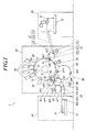
- the image formation unit 20 includes an image formation drum 50 to hold a recording medium P on its cylindrical outer periphery; a delivering unit 22 to deliver a recording medium, which has been conveyed by the conveying unit 12 of the paper feeding unit 10, to the image formation drum 50; a first heater 91 as a medium heater which heats a recording medium P held on the image formation drum 50; head units 70 to eject ink onto a recording medium P held on the image formation drum 50 to form an image; a cleaning unit 60 (see FIG.
- an irradiating unit 93 as an energy-ray irradiator which emits energy rays for curing ink ejected onto a recording medium P
- a conveying mechanism 80 which receives a recording medium P, which has been irradiated by the irradiating unit 93, from the image formation drum 50 and selects and performs either conveying the received recording medium P to the paper output unit 30 or turning over the received recording medium P to return it to the image formation drum 50
- a second heater 94 as a drum heater which directly heats the outer periphery of the image formation drum 50 with no recording medium P between the second heater 94 and the drum 50.
- the image formation drum 50 includes nail parts 51 and a suction part 212 to hold a recording medium P on the outer periphery of the image formation drum 50.
- a drum rotation motor 53 (see FIG. 5 ) is provided to rotate the image formation drum 50 in a predetermined conveyance direction F (counterclockwise direction in FIG. 1 ).
- the image formation drum 50 has three equal recording medium P holding areas, into which the outer periphery of the image formation drum 50 is divided. In other words, a maximum of three recording media P can be held on the image formation drum 50.
- the nail parts 51 are disposed at the boundaries of the three recording medium P holding areas, i.e., disposed at intervals of 120° about the rotation axis of the image formation drum 50.
- Each of the three nail parts 51 includes a plurality of nails arranged in a row in the direction of the rotation axis (X direction) on the outer periphery of the cylindrical image formation drum 50.
- the position at which a nail part 51 allows transfer of a recording medium P from the delivering unit 22 to the image formation drum 50 by the rotation of the image formation drum 50 is referred to as a supply position m1
- the positon at which a nail part 51 allows transfer of a recording medium P from the image formation drum 50 to the conveying mechanism 80 is referred to as a reception position m2.
- the image formation drum 50 is provided with a cam mechanism (not shown) to provide an opening motion for the nails of the nail parts 51 to be released when the nail parts 51 come to the supply position m1 and the reception position m2.
- the nail parts 51 come to the supply position m1 with their nails open.
- the nail parts 51 close their nails to catch the end of a recording medium P.
- the nail parts 51 thus receive the recording medium P from the delivering unit 22 and start conveying the recording medium P.
- the nails of the nail parts 51 are opened to release a recording medium P which has been conveyed.
- the nails are closed when the nail parts 51 leave the reception position m2, and then the empty holding area moves downstream.
- the reception position m2 is equivalent to "reception position downstream of the recording head in the conveyance direction)".
- the suction part 52 includes a plurality of suction holes and a suction generating part (e.g. , an air pump, fan, or injector).
- the suction holes are disposed in the outer periphery of the image formation drum 50, on which a recording medium P is to lie while an end of the recording medium P is caught by a nail part 51.
- the suction generating part generates suction force to suck gas into the image formation drum 50 through the suction holes.
- the suction part 52 allows a recording medium P to stick to the outer periphery of the image formation drum 50 so as to lie along the outer periphery with the suction force generated by suction through the suction holes.
- the internal space of the image formation drum 50 is divided into three compartments corresponding to the three recording medium P holding areas, respectively.
- a suction circuit 54 (see FIG. 5 ) is provided that selects the suction part 52 for an individual holding area to give suction force to the selected holding area. This configuration can operate the suction part 52 not to give suction force to a holding area that is not holding a recording medium P, preventing the reduction of suction force of the suction part 52 for a holding area that is not holding a recording medium P. Such reduction of suction force would occur if the internal space of the image formation drum 50 is not divided into compartments.
- FIG. 2 a part of the recording medium P is turned up from the outer periphery of the image formation drum 50 for the purpose of showing the suction holes. In reality, however, an entire recording medium P is held on the outer periphery of the image formation drum 50 so as to lie along the outer periphery at the time of image formation by the image formation unit 20.
- the delivering drum 222 has one nail part 223 to tightly hold one end of a recording medium P with the same structure as that of the nail parts 51 of the image formation drum 50.
- the delivering drum 222 is provided with a cam mechanism that opens and closes the multiple nails constituting the nail part 223 to allow the nails to receive and deliver a recording medium P.
- the cam mechanism closes the nails of the nail part 223 to catch a recording medium when the nail part 223 comes to the transfer position m3 where the nail part 223 is close to and faces the delivering nail part 221.
- the cam mechanism opens the nails of the nail part 223 to allow a recording medium to be transferred to the image formation drum 50 when the nail part 223 comes to the supply position m1 where the nail part 223 is close to and faces a nail part 51 of the image formation drum 50.
- a gear mechanism (not shown) allows the linkage of the delivering drum 222 and the image formation drum 50 in such a way that the rotation of the image formation drum 50 by one recording medium P holding area (i.e., 120°) makes a full revolution of the delivering drum 222 in the direction opposite to that of the image formation drum 50.
- each head unit 70 includes a plurality of recording heads 71, an ink tank 72 to store ink to be supplied to the recording heads 71, and an ink heater 73 to heat the ink before being ejected in ink paths (not shown) connecting the ink tank 72 and the recording heads 71 for temperature regulation of the ink.
- the conveying mechanism 80 includes a first conveyance drum 81 to receive a recording medium P from the image formation drum 50, a second conveyance drum 82 to receive a recording medium P from the first conveyance drum 81, a paper output drum 83 to receive a recording medium P from the second conveyance drum 82, a paper output belt mechanism 84 to receive a recording medium P from the paper output drum 83 to deliver the recording medium P to the paper output unit 30, an inversion drum 85 to receive a recording medium P from the second conveyance drum 82, and an inversion arm 86 to pull a recording medium P away from the inversion drum 85 and give the recording medium P to a nail part 51 of the image formation drum 50.
- the first conveyance drum 81 has one nail part 811 to tightly hold one end of a recording medium P with the same structure as that of the nail parts 51 of the image formation drum 50.
- a cam mechanism is provided that opens and closes the multiple nails constituting the nail part 811 to allow the nails to receive and deliver a recording medium P when the nail part 811 of the first conveyance drum 81 is at the reception position m2 and the transfer position m4.
- the reception position m2 is the position at which a recording medium P is transferred from the formation drum 50 to the first conveyance drum 81.
- the transfer position m4 is the position at which a recording medium P is transferred from the first conveyance drum 81 to the second conveyance drum 82.
- a gear mechanism (not shown) allows the linkage of the first conveyance drum 81 and the image formation drum 50 in such a way that the rotation of the image formation drum 50 by one recording medium P holding area (i.e., 120°) makes a full revolution of the first conveyance drum 81 in the direction opposite to that of the image formation drum 50.
- the second conveyance drum 82 has one nail part 821 to tightly hold one end of a recording medium P with the same structure as that of the nail parts 51 of the image formation drum 50.
- a cam mechanism is provided that opens and closes the multiple nails constituting the nail part 821 to allow the nails to receive and deliver a recording medium P when the nail part 821 of the second conveyance drum 82 is at (1) the transfer position m4 at which a recording medium P is transferred from the first conveyance drum 81 to the second conveyance drum 82, (2) the transfer position m5 at which a recording medium P is transferred from the second conveyance drum 82 to the paper output drum 83, and (3) the transfer position m6 at which a recording medium P is transferred from the second conveyance drum 82 to the inversion drum 85.
- the cam mechanism can switch between two operation states under the control of the control unit 40, as described later.
- the image formation device 1 can select one of image formation on only the front side of a recording medium P and image formation on both of the front and back sides.
- image formation on only the front side is performed in succession, a recording medium P is transferred from the second conveyance drum 82 to the paper output drum 83 each time to be output.
- the control unit 40 controls an actuator to switch the operation of the cam mechanism so that the nail part 821 operates in the states of (1) and (2) described above. In the state of (3) described above, the nail part 821 operates with no recording medium P held.
- the three recording medium holding areas of the image formation drum 50 alternately receive a recording medium P from the delivering unit 22. Accordingly, the second conveyance drum 82 alternately receives a recording medium P from the first conveyance drum 81 to deliver it to the inversion drum 85 and receives a recording medium P from the first conveyance drum 81 to deliver it to the paper output drum 83.
- every other holding area of the recording medium holding areas on the image formation drum 50 is empty at the beginning of image formation, but the recording media P passing the inversion drum 85 and turned over are returned to the empty areas.
- a recording medium P with its front side facing outward and a recording medium P with its back side facing outward are arranged alternately on the image formation drum 50.
- the recording medium P on which image formation has been performed with its back side facing outward is output, whereas the recording medium P on which image formation has been performed with its front side facing outward is turned over to be returned to the image formation drum 50.
- the inversion drum 85 which has a diameter about twice as large as the diameter of the second conveyance drum 82, is rotated by a later-described inversion motor 861 (see FIG. 5 ), which is an independent drive source.
- the inversion arm 86 has a nail at its tip to catch an end of a recording medium P.
- the tip of the inversion arm 86 can swing between the position at which the tip of the inversion arm 86 is in contact with the outer periphery of the inversion drum 85 and the positon at which the tip of the inversion arm 86 is in contact with the outer periphery of the image formation drum 50.
- the transfer of a recording medium P from the inversion drum 85 to the inversion arm 86 is performed as follows: the nail part 851 of the inversion drum 85 conveying a recording medium P passes the position close to and facing the inversion arm 86; when the nail part 851 comes to the transfer position m8 at which the end, not held by the nail part 851, of the recording medium P (i.e., the end on the upstream side in the conveyance direction) is close to the inversion arm 86, the nail of the inversion arm 86 catches the end of the recording medium P (i.e., the end not held by the nail part 851); and at the same time, the nail part 851 releases the recording medium P with the cam mechanism.
- the return position m9 is equivalent to "return position downstream of the reception position in the conveyance direction and upstream of the supply position in the conveyance direction".
- Each of the first conveyance drum 81, the second conveyance drum 82, the paper output drum 83, and the paper output belt mechanism 84 of the conveying mechanism 80 rotates in conjunction with the image formation drum 50 with a gear mechanism (not shown); and the inversion arm 86 swings in conjunction with the image formation drum 50. Only the inversion drum 85 is rotated by the inversion motor 861 (see FIG. 5 ) because the length of a recording medium P in the conveyance direction varies depending on the size of the recording medium P.
- the rotation speed needs to be controlled according to the size of the recording medium P so that the end, not held by the nail part 851, of the recording medium P reaches the position close to and facing the inversion arm 86. For this reason, the rotation speed of the inversion motor 861 is controlled independently of the rotation of the image formation drum 50.
- the second heater 94 is a lamp heater, such as a non-contact halogen lamp for infrared irradiation, and includes a reflector, having the same configuration as that of the first heater 91, to efficiently irradiate and heat the outer periphery of the image formation drum 50.
- the conveying mechanism 80 is required to pull a recording medium P away from the image formation drum 50 at the reception position m2 to turn over the recording medium P, and is required to return the recording medium P to the return position m9 of the image formation drum 50, to achieve the function of turning over recording media P. Accordingly, a recording medium P does not exist on the region from the reception position m2 to the return position m9 of the image formation drum 50 in the conveyance direction F. In the case of image formation on only the front side, a recording medium P is pulled away from the image formation drum 50 at the reception position m2 to be output. In this case, too, therefore, a recording medium P does not exist on the region from the reception position m2 to the return position m9 of the image formation drum 50 in the conveyance direction F.
- the second heater 94 is disposed to face the region from the reception position m2 to the return position m9 of the image formation drum 50 in the conveyance direction F. Thus, the second heater 94 can heat the outer periphery of the image formation drum 50 without a recording medium P between the second heater 94 and the image formation drum 50 at any time.
- a temperature sensor 95 to detect the temperature of the outer periphery of the image formation drum 50 is disposed near the second heater 94 and downstream of the second heater 94 in the conveyance direction.
- a contact temperature detection element such as a thermocouple and a thermistor, may be used as the temperature sensor 95, but a non-contact temperature detection element, such as a thermopile, is more preferable.
- the control unit 40 controls the heating operation of the second heater 94 on the basis of the temperature detected by the temperature sensor 95 so that the outer periphery of the image formation drum 50 passing near the second heater 94 becomes a predetermined temperature.
- the paper output unit 30 includes a plate paper output tray 31 on which recording media P sent from the image formation unit 20 by the conveying mechanism 80 are placed. Recording media P on which images have been formed are held in the paper output unit 30 until picked up by a user.
- the ink used in the present invention is an activating beam curable ink which is cured by being irradiated with energy rays (activating beams).
- the ink has the property of changing phase between gel or solid and liquid depending on the temperature of the ink.
- gelation used in the present invention refers to a solidified, semi-solidified, or thickened state accompanied by sharp increases in viscosity and elasticity; for example, a lamella structure, a polymer network formed by non-covalent bonds or hydrogen bonds, a polymer network formed by physical aggregation, and an aggregated structure composed of substances each immobilized by interactions between fine particles or between deposited fine crystals.
- the term “solation” refers to a liquid state in which the interactions formed during the gelation are released.
- solation temperature used in the present invention refers to an elevated temperature at which a gel ink is transformed into a sol state having fluidity.
- gelation temperature refers to a cooled temperature at which a sol ink is transformed into a gel state having reduced fluidity.
- the activating beam curable ink which exhibits such so-gel phase transition, is transformed into a liquid state at an elevated temperature, and thus can be ejected from recording heads.
- ink drops on a recording medium are spontaneously cooled and rapidly solidified by a temperature difference between the ink drops and the recording medium. This can prevents poor quality of an image due to integration of adjacent dots.
- ink drops that are readily solidified may be isolated from each other to form a rough image. The roughness may lead to inhomogeneous gloss such as extremely low gloss and unnatural glitter.
- printing or image formation with the ink which contains a gelling agent in an amount ranging of 0.1 percent by mass or more but less than 10 percent by mass and has a viscosity of 10 2 mPa ⁇ s or higher but lower than 10 5 mPa ⁇ s at 25°C under the control of the difference between the gelation temperature (T gel ) of ink with the gelling agent and the surface temperature (T s ) of the recording medium within the range of 5 to 15°C can prevent integration of the ink drops and thus simultaneously achieve high image quality and natural gloss on an image.
- the temperature of the recording medium is controlled within the range of 42 to 48°C.
- the ink containing a gelling agent in an amount of 0.1 percent by mass or more but less than 10 percent by mass and exhibiting a viscosity of 10 2 mPa ⁇ s or higher but lower than 10 5 mPa ⁇ s at 25°C allows the viscosity of the ink to be controlled within the temperature range of substrate. This control can simultaneously achieve high image quality and natural gloss on an image. Such a finding is based on the following assumption: the ink having viscosity lower than 10 2 mPa ⁇ s at 25°C cannot sufficiently prevent the integration of ink drops, and thus causes poor image quality within the above-described temperature range.
- the ink having viscosity of 10 5 mPa ⁇ s or higher at 25°C may exhibit high viscosity after gelation and cause a noticeable increase in viscosity during a cooling process.
- the viscosity of such an ink is barely controlled to an extent to be properly leveled within the above-described temperature range, which may reduce the gloss of an image.
- the ink of the present invention which is transformed into a viscous gel having proper viscosity after gelation, can effectively inhibit the solidification of the dots, and thus achieve image quality exhibiting relatively natural gloss.
- homogeneous gloss in the present invention does not define an absolute gloss, e.g., a specular reflection gloss at 60 degree. It, however, refers to entirely homogeneous gloss of an image (in particular, a solid image) without partially inhomogeneous gloss of the image, e.g., unnatural glitter, undesirable decreases in gloss, and stripe inconsistencies in gloss on the image, due to microscopic differences in gloss.
- the activating beam curable ink described in the present invention under the control of the difference between the gelation temperature (T gel ) of the ink and the surface temperature (T s ) of the recording medium within the range of 5 to 15°C can prevent poor image quality, and achieve high image quality exhibiting high sharpness of fine lines in characters and natural gloss.
- the temperature of the recording medium is preferably controlled within the range of 5 to 10°C.
- composition of the activating beam curable ink used in the present invention will now be described in sequence.
- gelation refers to a solidified, semi-solidified, or thickened state accompanied by sharp increases in viscosity and elasticity; for example, a lamella structure, a polymer network formed by non-covalent bonds or hydrogen bonds, a polymer network formed by physical aggregation, and an aggregate structure composed of substances each immobilized by interactions between fine particles or between deposited fine crystals.
- Typical examples of gels include a thermoreversible gel and a non-thermoreversible gel.
- the thermoreversible gel is transformed into a fluid solution (also referred to as "sol") when heated, while it is reversibly transformed into gel when cooled.
- the non-thermoreversible gel is not reversibly transformed into a fluid solution when heated once it gelates.
- the gel of the present invention which contains an oil gelling agent, is preferably a thermoreversible gel to prevent clogging of the heads.
- the gelation temperature (phase transition temperature) of the activating beam curable ink of the present invention is preferably 40°C or higher but lower than 100°C, and more preferably, 45°C or higher but 70°C or lower.
- an ink exhibiting a phase transition at a temperature of 40°C or higher can be stably ejected from recording heads regardless of the environment temperature during printing or image formation.
- An ink exhibiting a phase transition at a temperature lower than 90°C eliminates the need for heating of the image formation device 1 to an extremely high temperature, which can reduce load on the recording heads 71 of and the components of the ink supply system of the image formation device 1.
- a gelation temperature of ink in the present invention is calculated from a viscosity curve and a viscoelasticity curve observed with, for example, a rheometer (e.g., a stress controlled rheometer having a cone-plate, PhysicaMCR, Anton Paar Ltd.).
- the viscosity curve is observed during a temperature change in a sol ink at an elevated temperature under a low shear rate, whereas the viscoelasticity curve is observed during a measurement of a temperature change dependent on dynamic viscoelasticity.
- One example technique to obtain a gelation temperature involves placing a small piece of iron sealed in a glass tube into a dilatometer.
- a temperature at which the piece of iron in the ink liquid stops free-falling is determined to be a phase transition point ( J.Polym.Sci., 21, 57 (1956 )).
- Another example technique involves placing an aluminum cylinder on an ink to be subjected to a temperature change for gelation. A temperature at which the aluminum cylinder begins free-falling is determined to be a gelation temperature ( Nihon Reoroj i Gakkaishi (Journal of the Society of Rheology, Japan), Vol.17, 86(1989 )).
- An example simple technique involves placing a specimen in a gel state on a heat plate to be heated. A temperature at which the shape of the specimen collapses is determined to be a gelation temperature.
- Such a gelation temperature (phase transition temperature) of an ink can be controlled depending on the type of the gelling agent, the amount of the added gelling agent, and the type of the activating beam curable monomer.
- the ink applied to the present invention preferably has a viscosity of 10 2 mPa ⁇ s or higher but lower than 10 5 mPa ⁇ s at 25°C, and more preferably, of 10 3 mPa ⁇ s or higher but lower than 10 4 mPa ⁇ s.
- Ink having a viscosity of 10 2 mPa ⁇ s or higher can prevent poor image quality due to the integration of dots, while ink having a viscosity of lower than 10 5 mPa ⁇ s can be properly leveled after being ejected onto a recording medium under a controlled surface temperature of the recording medium, and thus can provide homogeneous gloss.
- the viscosity of the ink can be appropriately controlled depending on the type of the gelling agent, the amount of the added gelling agent, and the type of the activating beam curable monomer.
- the viscosity of the ink in the present invention is observed with a stress controlled rheometer including a cone-plate (PhysicaMCR, Anton Paar, Ltd.), at a shear rate of 11.7 s -1 .
- Non-limiting specific examples of the gelling agents which can be formulated in the ink according to the present invention are listed below.
- high-molecular compounds preferably used in the present invention include fatty acids with inulin, such as inulin stearate; dextrins of fatty acids, such as dextrin palmitate and dextrin myristate (Rheopearl, available from Chiba Flour Milling Co., Ltd.); glyceryl behenate/eicosadioate; and polyglyceryl behenate/eicosadioate (Nom Coat, available from The Nisshin Oillio Group, Ltd.).
- low-molecular compounds preferably used in the present invention include oil gelling agents having low molecular weight; amid compounds, such as N-lauroyl-L-glutamic acid dibutylamide and N-2-ethylhexanoyl-L-glutamic acid dibutylamide (availablefrom Ajinomoto Fine-Techno Co.
- the ink used in the present invention which contains the gelling agent, is transformed into a gel state immediately after being ejected from a recording head 71 onto a recording medium. This prevents the mixing and integration of dots and thus can provide high quality image during high-speed printing or image formation.
- the ink dots are then cured by activating beams to be fixed on the recording medium, forming a firm image film.
- the amount of the gelling agent included in the ink is preferably 1 percent by mass or more but less than 10 percent by mass, and more preferably, 2 percent by mass or more but less than 7 percent by mass.
- the ink containing the gelling agent in an amount of 1 percent by mass or more can be subj ected to sufficient gelation and thus can prevent poor image quality due to the integration of the dots.
- the ink of the present invention contains a gelling agent, coloring material, and an activating beam curable composition to be cured by activating beams.
- Examples of the activating beams used in the present invention include electron beams, ultraviolet rays, ⁇ beams, ⁇ beams, and x-rays; however, ultraviolet rays and electron beams are preferred that are less damaging the human body, easy to handle, and industrially widespread. In the present invention, ultraviolet rays are particularly preferred.
- aromatic epoxides include di- or poly-glycidyl ethers prepared by the reaction of polyhydric phenol having at least one aromatic nucleus or an alkylene oxide adduct thereof with epichlorohydrin, such as diglycidyl or polyglycidyl ethers of bisphenol A or an alkylene oxide adduct thereof, diglycidyl or polyglycidyl ethers of hydrogenated bisphenol A or an alkylene oxide adduct thereof, and novolac epoxy resin.
- alkylene oxides include ethylene oxide and propylene oxide.
- Preferred examples of alicyclic epoxides include a cyclohexene oxide-containing compound and a cyclopentane oxide-containing compound that are prepared by epoxidizing a compound having at least one cycloalkane ring such as a cyclohexene ring and a cyclopentene ring with a proper oxidant, such as hydrogen peroxide and a peracid.
- aliphatic epoxides include diglycidyl or polyglycidyl ethers of aliphatic polyhydric alcohols or alkylene oxide adducts thereof.
- Representative examples of the diglycidyl or polyglycidyl ethers include diglycidyl ethers of alkylene glycols, such as diglycidyl ether of ethylene glycol, diglycidyl ether of propylene glycol, and diglycidyl ether of 1,6-hexanediol; polyglycidyl ethers of polyhydric alcohols, such as diglycidyl ether or triglycidyl ether of glycerine or alkylene oxide adducts thereof; and diglycidyl ethers of polyalkylene glycols, such as diglycidyl ethers of polyethylene glycol or alkylene oxide adducts thereof, and diglycidyl ethers of polypropylene glycol or alky
- Preferred epoxides among these epoxides are aromatic epoxides and alicyclic epoxides, and more preferred are alicyclic epoxides because of their rapid curability.
- the above-described epoxides may be used alone or in combination as appropriate.
- oxetane compound used in the present invention refers to a compound having one or more oxetane rings. Any known oxetane compound may be used, for example, described in Japanese Unexamined Patent Application Publication Nos. 2001-220526 and 2001-310937 .
- an oxetane compound having five or more oxetane rings in the present invention may lead to an increase in viscosity of the ink composition.
- Such an ink composition is hard to handle, has a high glass transition temperature, and thus exhibits low adhesion after curing.
- the oxetane compound used in the present invention thus is preferably a compound having one to four oxetane rings.
- oxetane compounds include example compounds 1 to 6 described in paragraphs [0104] to [0119], and compounds described in paragraph [0121] of Japanese Unexamined Patent Application Publication No. 2005-255821 .
- any known radically polymerizable monomers may be used as photo-radically polymerizable monomers.
- Example of the known radically polymerizable monomers include photo-curable material prepared using photo-polymerizable compounds, and cationically polymerizable photo-curable resin, which are described in Japanese Unexamined Patent Application Publication No. 7-159983 , Japanese Examined Patent Application Publication No. 7-31399 , and Japanese Unexamined Patent Application Publication Nos. 8-224982 and 10-863 .
- photo-cationically polymerizable photo-curable resin that is sensitized to light having wavelengths longer than those of visible light may also be used, the resin being described in Japanese Unexamined Patent Application Publication Nos. 6-43633 and No. 8-324137 , for example.
- Radically polymerizable compounds have radically polymerizable ethylenically unsaturated bonds. Any radically polymerizable compound that has at least one radically polymerizable ethylenically unsaturated bond in a molecule may be used that has a chemical form such as a monomer, oligomer, or polymer. Such radically polymerizable compounds may be used alone or in combination in any proportion to improve target properties.
- Examples of the compounds having the radically polymerizable ethylenically unsaturated bond(s) include unsaturated carboxylic acids, such as acrylic acid, methacrylic acid, itaconic acid, crotonic acid, isocrotonic acid, and maleic acid, and salts, esters, urethanes, amides, anhydrides thereof; acrylonitrile; styrene; and radically polymerizable compounds such as various unsaturated polyesters, unsaturated polyethers, unsaturated polyamides, and unsaturated urethanes.
- unsaturated carboxylic acids such as acrylic acid, methacrylic acid, itaconic acid, crotonic acid, isocrotonic acid, and maleic acid
- salts, esters, urethanes, amides, anhydrides thereof acrylonitrile; styrene
- radically polymerizable compounds such as various unsaturated polyesters, unsaturated polyethers, unsaturated polyamides
- any known (meth)acrylate monomers and/or oligomers may be used as radically polymerizable compounds for the present invention.
- the term "and/or” used in the present invention means that the radically polymerizable compound may be a monomer, oligomer, or combination thereof. The same is applied to the term "and/or" in the following description.
- Example compounds having (meth)acrylate groups include monofunctional monomers, such as isoamyl acrylate, stearyl acrylate, lauryl acrylate, octyl acrylate, decyl acrylate, isomyristyl acrylate, isostearyl acrylate, 2-ethylhexyl diglycol acrylate, 2-hydroxybutyl acrylate, 2-acryloyloxyethyl hexahydrophthalate, butoxyethyl acrylate, ethoxydiethylene glycolacrylate, methoxydiethylene glycolacrylate, methoxypolyethylene glycolacrylate, methoxypropylene glycolacrylate, phenoxyethyl acrylate, tetrahydrofurfuryl acrylate, isobornyl acrylate, 2-hydroxyethyl acrylate, 2-hydroxypropyl acrylate, 2-hydroxy 3-phenoxypropyl acrylate, 2-acryloyloxy ethy
- polymerizable oligomers may be used as well.
- examples of the polymerizable oligomers include epoxy acrylates, aliphatic urethane acrylates, aromatic urethane acrylates, polyester acrylates, linear acylic oligomers.
- the preferred monomers include isoamyl acrylate, stearyl acrylate, lauryl acrylate, octyl acrylate, decyl acrylate, isomyristyl acrylate, isostearyl acrylate, ethoxydiethylene glycol acrylate, methoxypolyethylene glycol acrylate, methoxypropylene glycol acrylate, isobornyl acrylate, lactone-modified flexible acrylate, tetraethylene glycol diacrylate, polyethylene glycol diacrylate, polypropylene glycol diacrylate, dipentaerythritol hexaacrylate, di(trimethylolpropane) tetraacrylate, glycerine propoxy triacrylate, caprolactone-modified trimethylolpropane triacrylate, pentaerythritol ethoxy tetraacrylate, and caprolactam-modified dipentaerythritol
- more preferred monomers among these monomers are stearyl acrylate, lauryl acrylate, isostearyl acrylate, ethoxydiethylene glycol acrylate, isobornyl acrylate, tetraethylene glycol diacrylate, glyceryl propoxy triacrylate, caprolactone-modified trimethylolpropane triacrylate, and caprolactam-modified dipentaerythritol hexaacrylate.
- the polymerizable compound of the present invention may be combinations of vinyl ether monomer and/or oligomer and (meth) acrylate monomer and/or oligomer.
- the vinyl ether monomers include di- or tri-vinyl ether compounds, such as ethylene glycol divinyl ether, diethylene glycol divinyl ether, triethylene glycol divinyl ether, propylene glycol divinyl ether, dipropylene glycol divinyl ether, butanediol divinyl ether, hexanediol divinyl ether, cyclohexane dimethanol divinyl ether, and trimethylolpropane trivinyl ether; and monovinyl ether compounds, such as ethyl vinyl ether, n-butyl vinyl ether, isobutyl vinyl ether, octadecyl vinyl ether, cyclohexyl vinyl ether, hydroxybutyl vinyl ether, 2-ethy
- the polymerizable compound of the present invention may be combinations of various vinyl ether compounds and maleimide compounds.
- the maleimide compounds include N-methylmaleimide, N-propylmaleimide, N-hexylmaleimide, N-laurylmaleimide, N-cyclohexylmaleimide, N-phenylmaleimide, N,N'-methylenebismaleimide, polypropylene glycol bis(3-maleimidepropyl) ether, tetraethylene glycol bis(3-maleimidepropyl) ether, bis(2-maleimide ethyl) carbonate, N,N'-(4,4'-diphenylmethane) bismaleimide, N,N'-2,4-tolylene bismaleimide, and multifunctional maleimide compounds which are ester compounds containing maleimide carboxylic acids and various polyols, the multifunctional maleimide compound being described in Japanese Unexamined Patent Application Publication No. 11-124403 .
- the amount of added cationic polymerizable compound or radically polymerizable compound described above is preferably within a range of 1 to 97 percent by mass, and more preferably, of 30 to 95 percent by mass.
- the ink of the present invention may contain any dye or pigment as a color material.
- the preferred materials are pigments with stable dispersion in the ink components and weatherability.
- Examples of pigments according to the invention include, but not limited to, organic and inorganic pigments represented by the following color index numbers, which can be used in accordance with the purpose.
- Red or magenta pigments Pigment Reds 3, 5, 19, 22, 31, 38, 43, 48:1, 48:2, 48:3, 48:4, 48:5, 49:1, 53:1, 57:1, 57:2, 58:4, 63:1, 81, 81:1, 81:2, 81:3, 81:4, 88, 104, 108, 112, 122, 123, 144, 146, 149, 166, 168, 169, 170, 177, 178, 179, 184, 185, 208, 216, 226, and 257; Pigment Violets 3, 19, 23, 29, 30, 37, 50, and 88; and Pigment Oranges 13, 16, 20, and 36.
- Green pigments Pigment Greens 7, 26, 36, and 50.
- Yellow pigments Pigment Yellows 1, 3, 12, 13, 14, 17, 34, 35, 37, 55, 74, 81, 83, 93, 94, 95, 97, 108, 109, 110, 137, 138, 139, 153, 154, 155, 157, 166, 167, 168, 180, 185, and 193.
- Black pigments Pigment Blacks 7, 28, and 26.
- KET Yellows 401, 402, 403, 404, 405, 406, 416, and 424 KET Orange 501; KET Reds 301, 302, 303, 304, 305, 306, 307, 308, 309, 310, 336, 337, 338, and 346; KET Blues 101, 102, 103, 104, 105, 106, 111, 118, and 124; KET Green 201 (DIC Corporation), Colortex Yellows 301, 314, 315, 316, P-624, 314, U10GN, U3GN, UNN, UA-414, and U263; Finecol Yellows T-13 and T-05; Pigment Yellow 1705; Colortex Orange 202, Colortex Reds 101, 103, 115, 116, D3B, P-625, 102, H-1024, 105C, UFN, UCN, UBN, U3BN, URN, UGN, UG276, U456, U457, 105C, and
- the pigments may be dispersed, for example, with a ball mill, a sand mill, an attritor, a roll mill, an agitator, a Henschel mixer, a colloid mill, an ultrasonic homogenizer, a pearl mill, a wet jet mill, or a paint shaker.
- a dispersant may be added for dispersion of the pigments.
- the preferred dispersant is a polymer dispersant.
- polymer dispersants include Solsperse® series by Avecia Inc., PB series by Ajinomoto Fine-Techno Co., Inc., and the following materials.
- Pigment dispersants hydroxyl-containing carboxylic acid esters, salts of long-chain polyaminoamides and high-molecular-weight acid esters, salts of high-molecular-weight polycarboxylic acids, salts of long-chain polyaminoamides and polar acid esters, high-molecular-weight unsaturated acid esters, copolymers, modified polyurethanes, modified polyacrylates, polyether-ester anionic surfactants, salts of naphthalenesulfonic acid-formalin condensates, salts of aromatic sulfonic acid-formalin condensates, polyoxyethylene alkyl phosphate esters, polyoxyethylene nonylphenyl ethers, stearylamine acetates, and pigment derivatives.
- Still further examples include: DEMOLs RN, N (sodium naphthalene sulfonate-formaldehyde condensates), MS, C, SN-B (sodium aromatic sulfonate-formaldehyde condensates), and EP, HOMOGENOL L-18 (polycarboxylic polymer), EMULGENs920, 930, 931, 935, 950, and 985 (polyoxyethylene nonylphenyl ethers), ACETAMINs 24 (coconut amine acetate), and 86 (stearyl amine acetate) by Kao Corporation; SOLSPERSEs 5000 (phthalocyanine ammonium salt), 13240, 13940 (polyester amines), 17000 (aliphatic amine), 24000, and 32000 by AstraZeneca plc; and NIKKOL T106 (polyoxyethylene sorbitan monooleate), MYS-IEX (polyoxyethylene monostealate
- the ink preferably contains a pigment dispersant in an amount of 0.1 to 20 percent by mass. Synergists dedicated to the respective pigments may be used as dispersion aids. The dispersant and dispersion aids are preferably added in amounts of 1 to 50 parts by mass for 100 parts by mass of pigments.
- a dispersion medium may be a solvent or a polymerizable compound.
- the ink of the present invention which is subjected to reaction and curing after printing or image formation, contains no solvent. Residual solvent in cured-ink images causes a decrease in solvent resistance and problems of remaining volatile organic compound (VOC).
- the preferred dispersion media are therefore polymerizable compounds, especially a monomer with the lowest viscosity rather than a solvent, in view of dispersion characteristics.
- the pigment preferably has an average particle diameter in the range of 0.08 to 0.5 ⁇ m and a maximum diameter of 0.3 to 10 ⁇ m, more preferably 0.3 to 3 ⁇ m in view of dispersion of the pigment. These diameters are appropriately determined depending on the types of the pigment itself, dispersant, and dispersion medium, dispersion conditions, and filtration conditions. Such size control prevents nozzle clogging in the nozzles of the recording heads and leads to high storage stability, transparency, and curing sensitivity of the ink.
- MS Magenta VP, MS Magenta HM-1450, and MS Magenta HSo-147 Mitsubishi Chemicals, Inc.
- AIZENSOT Red-1, AIZEN SOT Red-2, AIZEN SOT Red-3, AIZEN SOT Pink-1, and SPIRON Red GEH SPECIAL Hodogaya Chemical Co., Ltd.
- RESOLIN Red FB 200%, MACROLEX Red Violet R, and MACROLEX ROT5B (Bayer) ; KAYASET Red B, KAYASET Red 130, and KAYASET Red 802 Nippon Kayaku Co.
- DAIWA Blue 7000 and Oleosol Fast Blue GL (Daiwa Kasei Co., Ltd.); DIARESIN Blue P (Mitsubishi Chemical Corporation); and SUDAN Blue 670, NEOPEN Blue 808, and ZAPON Blue 806 (BASF Japan Ltd.).
- MS Black VPC Mitsubishi Chemicals, Inc.
- AIZEN SOT Black-1 and AIZEN SOT Black-5 Hodogaya Chemical Co., Ltd.
- RESORIN Black GSN 200% and RESOLIN BlackBS Bayer
- KAYASET Black A-N Nippon Kayaku Co., Ltd.
- DAIWA Black MSC Daiwa Kasei Co., Ltd.
- HSB-202 Mitsubishi Chemical Corporation
- NEPTUNE Black X60 and NEOPEN Black X58 BASF Japan Ltd.
- the pigments or oil-soluble dyes are preferably added in amounts of 0.1 to 20 percent by mass, more preferably 0.4 to 10 percent by mass. Addition of 0.1 percent by mass or more yields desirable image quality, and addition of 20 percent by mass or less provides appropriate ink viscosity during ejection of ink. Two or more colorants may be appropriately used for color adjustment.
- the ink of the present invention preferably contains at least one photopolymerization initiator when ultraviolet rays, for example, are used as activating beams.
- at least one photopolymerization initiator when ultraviolet rays, for example, are used as activating beams.
- no photopolymerization initiator is necessary in many cases.
- Photopolymerization initiators are broadly categorized into two types: an intramolecular bonding cleavage type and an intramolecular hydrogen abstraction type.
- Photopolymerization initiators of the intramolecular bonding cleavage type include acetophenones, such as diethoxyacetophenone, 2-hydroxy-2-methyl-1-phenylpropan-1-one, benzyl dimethyl ketal, 1-(4-isopropylphenyl)-2-hydroxy-2-methylpropan-1-one, 4-(2-hydroxyethoxy)phenyl 2-hydroxy-2-propyl ketone, 1-hydroxycyclohexyl phenyl ketone, 2-methyl-2-morpholino(4-thiomethylphenyl)propan-1-one, and 2-benzyl-2-dimethylamino-1-(4-morpholinophenyl)-butanone; benzoins, such as benzoin, benzoin methyl ethers, and benzoin isopropyl ethers; acylphosphine oxides, such as 2,4,6-trimethyl benzoin diphenylphosphine oxide; benzyl; and methyl phen
- Photopolymerization initiators of the intramolecular hydrogen abstraction type include benzophenones, such as benzophenone, methyl-o-benzoylbenzoate-4-phenyl benzophenone, 4,4'-dichlorobenzophenone, hydroxybenzophenone, 4-benzoyl-4' -methyl diphenyl sulfide, acrylated benzophenone, 3,3',4,4'-tetra(t-butylperoxycarbonyl)benzophenone, and 3,3'-dimethyl-4-methoxy benzophenone; thioxanthones, such as 2-isopropylthioxanthone, 2,4-dimethylthioxanthone, 2,4-diethylthioxanthone, and 2,4-dichlorothioxanthone; aminobenzophenones, such as Michler's ketone and 4,4'-diethylamino benzophenone; 10-butyl-2-chloroa
- the preferred amount of a photopolymerization initiator, if used, is 0.01 to 10 percent by mass of an activating beam curable composition.
- radical polymerization initiators examples include triazine derivatives disclosed in documents, such as Japanese Examined Patent Application Publication Nos. S59-1281 and S61-9621 , and Japanese Unexamined Patent Application Publication No. S60-60104 ; organic peroxides disclosed in documents, such as Japanese Unexamined Patent Application Publication Nos. S59-1504 and S61-243807 ; diazonium compounds disclosed in documents, such as Japanese Examined Patent Application Publication Nos. S43-23684 , S44-6413 , S44-6413 , and S47-1604 and U. S. Patent No. 3, 567, 453 ; organic azide compounds disclosed in documents, such as U.S. Patent Nos.
- orthoquinonediazides disclosed in documents such as Japanese Examined Patent Application Publication Nos. S36-22062 , S37-13109 , S38-18015 , and S45-9610 ; onium compounds disclosed in documents, such as Japanese Examined Patent Application Publication No. S55-39162 and Japanese Unexamined Patent Application Publication No. S59-14023 and Macromolecules, 10, P. 1307, 1977 ; azo compounds disclosed in Japanese Unexamined Patent Application Publication No. S59-142205 ; metal allene complexes disclosed in documents, such as Japanese Unexamined Patent Application Publication No. H1-54440 , EP patent Nos.
- the preferred amount of a polymerization initiator ranges from 0.01 to 10 parts by mass for 100 parts by mass of a compound containing a radically polymerizable ethylenically unsaturated bond.
- the ink of the present invention may contain a photoacid generator serving as a photopolymerization initiator.
- photoacid generators compounds that are used, for example, for a chemically amplified photoresist or photo cationic polymerization are used (The Japanese Research Association for Organic Electronics Materials (ed.), Organic materials for imaging, pp. 187-192, BUNSHIN, 1993 ). Examples of such a compound suitable for the present invention are as follows.
- Second group salts of aromatic onium compounds, such as diazonium, ammonium, iodonium, sulfonium, and phosphonium with B(C 6 F 5 ) 4 - , PF 6 - , AsF 6 - , SbF 6 - , or CF 3 SO 3 - .
- aromatic onium compounds such as diazonium, ammonium, iodonium, sulfonium, and phosphonium with B(C 6 F 5 ) 4 - , PF 6 - , AsF 6 - , SbF 6 - , or CF 3 SO 3 - .
- Second group sulfonated compounds generating sulfonic acid. Specific examples of such a sulfonated compound are disclosed in paragraph [0136] of Japanese Unexamined Patent Publication No. 2005-255821 .
- Pigment dispersion elements for the following ink composition are obtained by heating and stirring a mixture of 5 parts by mass of SOLSPERSE 32000 (Lubrizol Corporation) and 80 parts by mass of HD-N (1,6-hexanediol dimethacrylate: Shin-Nakamura Chemical Co., Ltd.) in a stainless steel beaker to dissolve the mixture, cooling the mixture to room temperature, adding 15 parts by mass of Carbon Black #56 (Mitsubishi Chemical Corporation) to the mixture, putting the mixture and zirconia beads of 0.5 mm in a sealed glass vial, performing dispersion of the mixture with a paint shaker for 10 hours, and removing the zirconia beads therefrom.
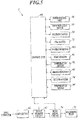
- FIG. 5 is a block diagram showing the main control configuration of the image formation device 1.
- the control unit 40 of the image formation device 1 is electrically connected to the paper feeding unit 10 to convey a recording medium P to the image formation unit 20, the drum rotation motor 53 to rotate the image formation drum 50, the suction circuit 54 for air suction for the drum 50, the ink heater 73 to heat the ink to be supplied to the heads 71, the inversion motor 861 to allow the rotation of the inversion drum 85, the first heater 91 to heat a recording medium P on the outer periphery of the image formation drum 50 before image formation, the temperature sensor 92 to detect the temperature of a recording medium P heated by the first heater 91, the irradiating unit 93 to irradiate with UV rays an ink image formed on a recording medium P, the second heater 94 to directly heat the outer periphery of the image formation drum 50 with no recording medium P between the second heater 94 and the image formation drum 50, the temperature sensor 95 to detect the temperature of the outer
- an image memory circuit 42 to store the data of image to be formed inputted from a host computer, a higher-level device, via an interface circuit 41 is provided in addition to the control unit 40.
- the CPU of the control unit 40 performs computing on the basis of image data stored in the image memory circuit 42 and the program, and sends a control signal to each component on the basis of the computing results.
- the image formation drum 50 is rotated by the drum rotation motor 53, the second heater 94 is turned on, and the outer periphery of the image formation drum 50 is heated to a target temperature on the basis of the temperature detected by the temperature sensor 95.
- the control unit 40 controls the paper feeding unit 10 to intermittently convey a recording medium P to every other recording medium holding area on the image formation drum 50 which is being rotated.
- the downstream end, in the conveyance direction, of the recording medium P supplied from the delivering unit 22 is caught with a nail part 51 of the image formation drum 50 at the supply position m1, and the recording medium P sticks to a holding area.
- the recording medium P that starts to be conveyed by the image formation drum 50 is heated to a predetermined target temperature by the first heater 91 controlled on the basis of the temperature detected by the temperature sensor 92.
- a plurality of heads 71 of each head unit 70 are then driven to form an image based on image data.
- the recording medium P is transferred to the first conveyance drum 81.
- the front side, on which an image has been formed, of the recording medium P comes into close contact with the outer periphery of the first conveyance drum 81, and the back side of the recording medium P is facing outward.
- the nail part 811 holding the downstream end, in the conveyance direction, of the recording medium P comes to the transfer position m4, the recording medium P is transferred to the second conveyance drum 82.
- the back side of the recording medium P comes into close contact with the outer periphery of the second conveyance drum 82, and the front side of the recording medium P is facing outward.
- the cam mechanism operates the nail part 821 so that the recording medium P goes forward without being transferred from the second conveyance drum 82 to the paper output drum 83. Further, when the nail part 821 holding the upstream end, in the conveyance direction, of the recording medium P comes to the transfer position m6, the recording medium P is transferred to the inversion drum 85. At this time, the front side of the recording medium P comes into close contact with the outer periphery of the inversion drum 85, and the back side of the recording medium P is facing outward.
- the nail part 851 holding the downstream end, in the conveyance direction, of the recording medium P comes to the transfer position m8, the upstream end, in the conveyance direction, of the recording medium P (i.e. , the end of the recording medium P opposite to the end held by the nail part 851) is close to and facing the tip of the of the inversion arm 86.
- the nail part 851 then cancels the holding state, and the upstream end, in the conveyance direction, of the recording medium P is caught by the tip of the inversion arm 86.
- the inversion arm 86 then swings to the image formation drum 50, and the end of the recording medium P, which is on the upstream side on the inversion drum 85 in the conveyance direction, is pulled to the return position m9, with the back side of the recording medium P remaining facing outward.
- the image formation drum 50 is controlled so that a nail part 51 of an empty recording medium holding area comes to the return position m9 at the same time as the end of the recording medium P being pulled to the return position m9.
- the end of the recording medium P which was originally on the upstream side in the conveyance direction, is caught by the nail part 51 with the back side of the recording medium P facing outward.
- the recording medium P is turned over, comes into close contact with the outer periphery of the image formation drum 50, and passes the supply position m1.
- Image formation then is performed on the back side through the same process as that in the image formation on the front side.
- the recording medium P is transferred from the image formation drum 50 to the first conveyance drum 81 at the reception position m2.
- the front side of the recording medium P is facing outward.
- the recording medium P is transferred from the first conveyance drum 81 to the second conveyance drum 82 at the transfer position m4. On the second conveyance drum 82, the back side of the recording medium P is facing outward.
- the recording medium P is then transferred from the paper output drum 83 to the paper output belt mechanism 84 at the transfer position m7, and the recording medium P is output to the paper output unit 30 with its back side facing outward.
- the present invention is applicable to the field of image formation devices to perform image formation on both sides of a recording medium where there is demand for image formation at a proper temperature.
Landscapes
- Health & Medical Sciences (AREA)
- General Health & Medical Sciences (AREA)
- Toxicology (AREA)
- Ink Jet (AREA)
- Particle Formation And Scattering Control In Inkjet Printers (AREA)
- Ink Jet Recording Methods And Recording Media Thereof (AREA)
Applications Claiming Priority (2)
| Application Number | Priority Date | Filing Date | Title |
|---|---|---|---|
| JP2012104619 | 2012-05-01 | ||
| PCT/JP2013/062643 WO2013165003A1 (fr) | 2012-05-01 | 2013-04-30 | Dispositif de formation d'image |
Publications (3)
| Publication Number | Publication Date |
|---|---|
| EP2845733A1 true EP2845733A1 (fr) | 2015-03-11 |
| EP2845733A4 EP2845733A4 (fr) | 2016-07-20 |
| EP2845733B1 EP2845733B1 (fr) | 2017-06-21 |
Family
ID=49514402
Family Applications (1)
| Application Number | Title | Priority Date | Filing Date |
|---|---|---|---|
| EP13784124.3A Active EP2845733B1 (fr) | 2012-05-01 | 2013-04-30 | Dispositif de formation d'image |
Country Status (5)
| Country | Link |
|---|---|
| US (1) | US9090080B2 (fr) |
| EP (1) | EP2845733B1 (fr) |
| JP (1) | JP6013461B2 (fr) |
| CN (1) | CN104284779B (fr) |
| WO (1) | WO2013165003A1 (fr) |
Cited By (4)
| Publication number | Priority date | Publication date | Assignee | Title |
|---|---|---|---|---|
| CN107709016A (zh) * | 2015-06-30 | 2018-02-16 | 小森公司 | 印刷设备 |
| EP3406452A1 (fr) * | 2017-05-24 | 2018-11-28 | OCE Holding B.V. | Imprimante couleur |
| DE102017218403A1 (de) * | 2017-10-13 | 2019-04-18 | Koenig & Bauer Ag | Bogendruckmaschine |
| US10882307B2 (en) | 2017-10-13 | 2021-01-05 | Koenig & Bauer Ag | Sheet-fed printing press |
Families Citing this family (14)
| Publication number | Priority date | Publication date | Assignee | Title |
|---|---|---|---|---|
| JP6874290B2 (ja) * | 2016-07-07 | 2021-05-19 | 株式会社リコー | 2次元又は3次元の像形成方法 |
| DE102017214689A1 (de) * | 2016-09-13 | 2018-03-15 | Heidelberger Druckmaschinen Ag | Digitaldruckmaschine |
| JP2018140784A (ja) * | 2017-02-27 | 2018-09-13 | 株式会社タケトモ | ブリスターパック包装体の蓋材用包装シートの製造方法 |
| CN107962881B (zh) * | 2017-12-28 | 2020-04-07 | 广东易美图影像科技股份有限公司 | 一种自动裁纸鼓式连续旋转喷墨打印机 |
| CN108215489B (zh) * | 2017-12-28 | 2020-01-07 | 广东易美图影像科技股份有限公司 | 一种便于喷头调节的鼓式连续旋转喷墨打印机 |
| CN108189578B (zh) * | 2017-12-28 | 2020-04-10 | 广东易美图影像科技股份有限公司 | 一种鼓式连续旋转喷墨打印方法 |
| CN108189558B (zh) * | 2017-12-28 | 2020-04-14 | 广东易美图影像科技股份有限公司 | 一种鼓式连续旋转喷墨打印机 |
| WO2020026244A1 (fr) | 2018-08-03 | 2020-02-06 | Scodix Ltd | Système d'impression à amélioration multiple modulaire |
| JP7187416B2 (ja) * | 2019-09-26 | 2022-12-12 | 富士フイルム株式会社 | インクジェット印刷装置 |
| JP7443731B2 (ja) * | 2019-11-27 | 2024-03-06 | コニカミノルタ株式会社 | 画像形成装置および画像形成制御方法 |
| JP7532956B2 (ja) | 2020-07-01 | 2024-08-14 | コニカミノルタ株式会社 | インクジェット記録装置及び記録媒体温度制御方法 |
| JP7567413B2 (ja) | 2020-12-03 | 2024-10-16 | コニカミノルタ株式会社 | 画像形成装置、及び画像形成装置の加熱方法 |
| JP2023082826A (ja) * | 2021-12-03 | 2023-06-15 | コニカミノルタ株式会社 | 画像形成装置、画像形成装置の制御方法および画像形成装置の制御プログラム |
| JP2024033684A (ja) * | 2022-08-31 | 2024-03-13 | コニカミノルタ株式会社 | インクジェット記録システム及び記録方法 |
Family Cites Families (64)
| Publication number | Priority date | Publication date | Assignee | Title |
|---|---|---|---|---|
| GB763288A (en) | 1954-06-16 | 1956-12-12 | Kodak Ltd | Improvements in photo mechanical processes and materials therefor |
| US2852379A (en) | 1955-05-04 | 1958-09-16 | Eastman Kodak Co | Azide resin photolithographic composition |
| US2940853A (en) | 1958-08-21 | 1960-06-14 | Eastman Kodak Co | Azide sensitized resin photographic resist |
| JPS3622062B1 (fr) | 1960-01-14 | 1961-11-15 | ||
| JPS3713109B1 (fr) | 1960-01-14 | 1962-09-06 | ||
| JPS3818015B1 (fr) | 1960-11-11 | 1963-09-12 | ||
| JPS4323684B1 (fr) | 1965-04-01 | 1968-10-12 | ||
| DE1550705B2 (de) | 1965-06-28 | 1975-05-22 | Caterpillar Tractor Co., (N.D.Ges. D.Staates Kalifornien), San Leandro, Calif. (V.St.A.) | Hydrodynamisch-mechanisches Wechselgetriebe |
| JPS459610B1 (fr) | 1965-07-19 | 1970-04-07 | ||
| US3567453A (en) | 1967-12-26 | 1971-03-02 | Eastman Kodak Co | Light sensitive compositions for photoresists and lithography |
| JPS471604B1 (fr) | 1968-12-06 | 1972-01-17 | ||
| US3987037A (en) | 1971-09-03 | 1976-10-19 | Minnesota Mining And Manufacturing Company | Chromophore-substituted vinyl-halomethyl-s-triazines |
| US4026705A (en) | 1975-05-02 | 1977-05-31 | General Electric Company | Photocurable compositions and methods |
| JPS54151024A (en) | 1978-05-18 | 1979-11-27 | Fuji Photo Film Co Ltd | Photopolymerizable composition |
| JPS591504A (ja) | 1982-06-26 | 1984-01-06 | Nippon Oil & Fats Co Ltd | 光重合開始剤組成物 |
| JPS5914023A (ja) | 1982-07-15 | 1984-01-24 | Chugoku Denki Seizo Kk | フリツカ抑制装置の制御方式 |
| US5089536A (en) | 1982-11-22 | 1992-02-18 | Minnesota Mining And Manufacturing Company | Energy polmerizable compositions containing organometallic initiators |
| JPS59107344A (ja) | 1982-12-13 | 1984-06-21 | Hitachi Chem Co Ltd | 感光性樹脂組成物 |
| JPS59142205A (ja) | 1983-02-02 | 1984-08-15 | Nippon Oil & Fats Co Ltd | 高感度光開始剤組成物 |
| US5073476A (en) | 1983-05-18 | 1991-12-17 | Ciba-Geigy Corporation | Curable composition and the use thereof |
| JPS6060104A (ja) | 1983-09-12 | 1985-04-06 | Fuji Photo Film Co Ltd | 光重合性組成物 |
| US4713401A (en) | 1984-12-20 | 1987-12-15 | Martin Riediker | Titanocenes and a radiation-polymerizable composition containing these titanocenes |
| JPH0731399B2 (ja) | 1984-12-21 | 1995-04-10 | 三菱化学株式会社 | 光重合性組成物 |
| JPH0757765B2 (ja) | 1985-04-23 | 1995-06-21 | 日本油脂株式会社 | 光重合開始剤 |
| JPS6454440A (en) | 1987-08-24 | 1989-03-01 | Toyo Boseki | Photopolymerizable composition |
| US4954414A (en) | 1988-11-08 | 1990-09-04 | The Mead Corporation | Photosensitive composition containing a transition metal coordination complex cation and a borate anion and photosensitive materials employing the same |
| JP2775649B2 (ja) | 1989-10-13 | 1998-07-16 | 富士写真フイルム株式会社 | アルミナート錯体からなる光重合開始剤及び光重合性組成物 |
| JPH05169649A (ja) * | 1991-12-18 | 1993-07-09 | Ricoh Co Ltd | インクジェット記録装置 |
| JP2711491B2 (ja) | 1992-02-07 | 1998-02-10 | 東洋インキ製造株式会社 | スルホニウム錯体またはオキソスルホニウム錯体 |
| JP2803454B2 (ja) | 1992-03-13 | 1998-09-24 | 東洋インキ製造株式会社 | スルホニウム錯体またはオキソスルホニウム錯体 |
| JP3283329B2 (ja) | 1992-05-06 | 2002-05-20 | 協和醗酵工業株式会社 | 化学増幅型レジスト組成物 |
| JP3178091B2 (ja) | 1992-06-29 | 2001-06-18 | 住友化学工業株式会社 | 光重合性組成物及び光制御板の製造方法 |
| JPH0756462A (ja) * | 1993-06-30 | 1995-03-03 | Ricoh Co Ltd | 画像形成装置 |
| JP3223222B2 (ja) | 1993-12-03 | 2001-10-29 | 富士写真フイルム株式会社 | 感光性印刷版 |
| JPH08224982A (ja) | 1995-02-22 | 1996-09-03 | Konica Corp | 転写箔及びそれを用いたidカード |
| KR970058945A (ko) * | 1996-01-17 | 1997-08-12 | 김광호 | 열전사 프린터 |
| EP0800114B1 (fr) * | 1996-03-11 | 2003-11-05 | Fuji Photo Film Co., Ltd. | Procédé de formation d'image et système |
| JP3498279B2 (ja) | 1996-06-12 | 2004-02-16 | コニカミノルタホールディングス株式会社 | 熱転写シート及びそれを用いて形成した画像要素 |
| JP3040716B2 (ja) | 1996-07-01 | 2000-05-15 | コニカ株式会社 | 画像記録体およびその製造方法 |
| JPH10138526A (ja) * | 1996-11-11 | 1998-05-26 | Tec Corp | インクジェットプリンタ |
| JP3599160B2 (ja) | 1997-05-16 | 2004-12-08 | 大日本インキ化学工業株式会社 | マレイミド誘導体を含有する活性エネルギー線硬化性組成物及び該活性エネルギー線硬化性組成物の硬化方法 |
| JP2002517016A (ja) * | 1998-05-24 | 2002-06-11 | インデイゴ ナムローゼ フェンノートシャップ | プリントシステム |
| JP2000275937A (ja) * | 1999-03-24 | 2000-10-06 | Minolta Co Ltd | 潜像形成方法及び潜像形成装置 |
| JP3726568B2 (ja) | 1999-07-23 | 2005-12-14 | 東洋インキ製造株式会社 | 紫外線硬化型塗料組成物及びその利用 |
| JP2001040068A (ja) | 1999-07-27 | 2001-02-13 | Asahi Denka Kogyo Kk | 光重合性組成物 |
| JP4358375B2 (ja) | 1999-08-19 | 2009-11-04 | 関西ペイント株式会社 | 活性エネルギー線硬化性組成物およびその被膜形成方法 |
| JP3893833B2 (ja) | 2000-02-09 | 2007-03-14 | ブラザー工業株式会社 | インクジェット記録方式用エネルギー線硬化型組成物 |
| JP2001310937A (ja) | 2000-04-27 | 2001-11-06 | Hitachi Chem Co Ltd | 硬化性オキセタン組成物およびその硬化方法ならびにその方法により得られる硬化物 |
| JP2001310938A (ja) | 2000-04-28 | 2001-11-06 | Showa Denko Kk | 重合性組成物、その硬化物と製造方法 |
| JP2004082689A (ja) * | 2002-06-28 | 2004-03-18 | Fuji Photo Film Co Ltd | インクジェット記録装置 |
| JP4556414B2 (ja) | 2003-10-22 | 2010-10-06 | コニカミノルタホールディングス株式会社 | インクジェット用インク及びそれを用いたインクジェット記録方法 |
| JP4765256B2 (ja) | 2004-03-11 | 2011-09-07 | コニカミノルタホールディングス株式会社 | 活性光線硬化型インクジェットインクとそれを用いたインクジェット記録方法 |
| JP2006213415A (ja) * | 2005-02-01 | 2006-08-17 | Fuji Photo Film Co Ltd | インクジェット画像形成装置および方法 |
| JP2006232512A (ja) | 2005-02-28 | 2006-09-07 | Ricoh Co Ltd | 画像形成装置 |
| JP2008044235A (ja) * | 2006-08-16 | 2008-02-28 | Fujifilm Corp | インクジェット記録方法及び装置 |
| JP5195365B2 (ja) | 2008-01-23 | 2013-05-08 | セイコーエプソン株式会社 | インク吐出装置 |
| JP5335282B2 (ja) * | 2008-05-20 | 2013-11-06 | 富士フイルム株式会社 | インクジェット記録装置 |
| US7874664B2 (en) * | 2008-07-23 | 2011-01-25 | Xerox Corporation | Electrically conductive pressure roll surfaces for phase-change ink-jet printer for direct on paper printing |
| JP2010111790A (ja) | 2008-11-07 | 2010-05-20 | Konica Minolta Holdings Inc | 活性光線硬化型インクジェット用インクとそれを用いたインクジェット記録方法 |
| JP5276558B2 (ja) * | 2009-09-18 | 2013-08-28 | 富士フイルム株式会社 | 画像形成装置 |
| US8534826B2 (en) * | 2010-02-22 | 2013-09-17 | Fujifilm Corporation | Inkjet recording apparatus and method |
| JP5475528B2 (ja) * | 2010-04-09 | 2014-04-16 | 株式会社ミヤコシ | インクジェット記録装置 |
| US20120092431A1 (en) * | 2010-10-13 | 2012-04-19 | Toshiba Tec Kabushiki Kaisha | Recording medium carrying device, image forming apparatus, and recording medium carrying method |
| WO2012077736A1 (fr) * | 2010-12-10 | 2012-06-14 | コニカミノルタホールディングス株式会社 | Dispositif d'impression à jet d'encre |
-
2013
- 2013-04-30 EP EP13784124.3A patent/EP2845733B1/fr active Active
- 2013-04-30 CN CN201380022988.5A patent/CN104284779B/zh active Active
- 2013-04-30 US US14/398,694 patent/US9090080B2/en active Active
- 2013-04-30 WO PCT/JP2013/062643 patent/WO2013165003A1/fr not_active Ceased
- 2013-04-30 JP JP2014513400A patent/JP6013461B2/ja active Active
Cited By (9)
| Publication number | Priority date | Publication date | Assignee | Title |
|---|---|---|---|---|
| CN107709016A (zh) * | 2015-06-30 | 2018-02-16 | 小森公司 | 印刷设备 |
| EP3318404A4 (fr) * | 2015-06-30 | 2019-02-20 | Komori Corporation | Dispositif d'impression |
| US10265946B2 (en) | 2015-06-30 | 2019-04-23 | Komori Corporation | Printing apparatus |
| EP3620302A1 (fr) * | 2015-06-30 | 2020-03-11 | Komori Corporation | Appareil d'impression |
| EP3406452A1 (fr) * | 2017-05-24 | 2018-11-28 | OCE Holding B.V. | Imprimante couleur |
| US10518554B2 (en) | 2017-05-24 | 2019-12-31 | Océ Holding B.V. | Color printer |
| DE102017218403A1 (de) * | 2017-10-13 | 2019-04-18 | Koenig & Bauer Ag | Bogendruckmaschine |
| US10882307B2 (en) | 2017-10-13 | 2021-01-05 | Koenig & Bauer Ag | Sheet-fed printing press |
| DE102017218403B4 (de) | 2017-10-13 | 2023-04-06 | Koenig & Bauer Ag | Bogendruckmaschine |
Also Published As
| Publication number | Publication date |
|---|---|
| CN104284779A (zh) | 2015-01-14 |
| CN104284779B (zh) | 2016-03-09 |
| US9090080B2 (en) | 2015-07-28 |
| WO2013165003A1 (fr) | 2013-11-07 |
| JP6013461B2 (ja) | 2016-10-25 |
| US20150124029A1 (en) | 2015-05-07 |
| EP2845733B1 (fr) | 2017-06-21 |
| JPWO2013165003A1 (ja) | 2015-12-24 |
| EP2845733A4 (fr) | 2016-07-20 |
Similar Documents
| Publication | Publication Date | Title |
|---|---|---|
| EP2845733B1 (fr) | Dispositif de formation d'image | |
| US8814347B2 (en) | Inkjet recording device | |
| JP5867585B2 (ja) | インクジェット記録方法 | |
| US9340693B2 (en) | Actinic ray curable inkjet ink and image recording method using same | |
| EP2703173A1 (fr) | Dispositif d'impression à jet d'encre | |
| WO2012023368A1 (fr) | Encre durcissable par rayonnement actif et procédé d'enregistrement à jet d'encre durcissable par rayonnement actif | |
| JP5888145B2 (ja) | 画像形成装置 | |
| JP5867277B2 (ja) | インクジェット記録装置 | |
| JP5605199B2 (ja) | インクジェット記録装置及びインクジェット記録方法 | |
| JP5703954B2 (ja) | インクジェット記録方法 | |
| EP2979878B1 (fr) | Dispositif de formation d'image | |
| WO2015012364A1 (fr) | Unité de tête d'enregistrement et dispositif de formation d'image | |
| JP5811101B2 (ja) | インクジェット記録装置 | |
| JP5874518B2 (ja) | インクジェット記録装置 | |
| JP5673055B2 (ja) | インクジェット記録装置 | |
| JP2013230630A (ja) | インクジェット記録装置 | |
| JP2013230632A (ja) | インク供給ユニット | |
| JP2012121286A (ja) | インクジェット用画像形成ドラム及びインクジェット記録装置 |
Legal Events
| Date | Code | Title | Description |
|---|---|---|---|
| PUAI | Public reference made under article 153(3) epc to a published international application that has entered the european phase |
Free format text: ORIGINAL CODE: 0009012 |
|
| 17P | Request for examination filed |
Effective date: 20141030 |
|
| AK | Designated contracting states |
Kind code of ref document: A1 Designated state(s): AL AT BE BG CH CY CZ DE DK EE ES FI FR GB GR HR HU IE IS IT LI LT LU LV MC MK MT NL NO PL PT RO RS SE SI SK SM TR |
|
| AX | Request for extension of the european patent |
Extension state: BA ME |
|
| DAX | Request for extension of the european patent (deleted) | ||
| RA4 | Supplementary search report drawn up and despatched (corrected) |
Effective date: 20160622 |
|
| RIC1 | Information provided on ipc code assigned before grant |
Ipc: B41J 2/01 20060101AFI20160616BHEP Ipc: B41J 2/015 20060101ALI20160616BHEP Ipc: B41J 11/00 20060101ALI20160616BHEP Ipc: B41J 3/60 20060101ALI20160616BHEP Ipc: B41J 13/22 20060101ALI20160616BHEP Ipc: B41M 5/00 20060101ALI20160616BHEP |
|
| REG | Reference to a national code |
Ref country code: DE Ref legal event code: R079 Ref document number: 602013022618 Country of ref document: DE Free format text: PREVIOUS MAIN CLASS: B41J0002010000 Ipc: B41J0002175000 |
|
| GRAP | Despatch of communication of intention to grant a patent |
Free format text: ORIGINAL CODE: EPIDOSNIGR1 |
|
| RIC1 | Information provided on ipc code assigned before grant |
Ipc: B41J 13/22 20060101ALI20161108BHEP Ipc: B41J 2/175 20060101AFI20161108BHEP Ipc: B41J 3/60 20060101ALI20161108BHEP Ipc: B41J 11/00 20060101ALI20161108BHEP |
|
| INTG | Intention to grant announced |
Effective date: 20161128 |
|
| GRAS | Grant fee paid |
Free format text: ORIGINAL CODE: EPIDOSNIGR3 |
|
| GRAJ | Information related to disapproval of communication of intention to grant by the applicant or resumption of examination proceedings by the epo deleted |
Free format text: ORIGINAL CODE: EPIDOSDIGR1 |
|
| GRAL | Information related to payment of fee for publishing/printing deleted |
Free format text: ORIGINAL CODE: EPIDOSDIGR3 |
|
| GRAP | Despatch of communication of intention to grant a patent |
Free format text: ORIGINAL CODE: EPIDOSNIGR1 |
|
| INTC | Intention to grant announced (deleted) | ||
| GRAA | (expected) grant |
Free format text: ORIGINAL CODE: 0009210 |
|
| INTG | Intention to grant announced |
Effective date: 20170426 |
|
| AK | Designated contracting states |
Kind code of ref document: B1 Designated state(s): AL AT BE BG CH CY CZ DE DK EE ES FI FR GB GR HR HU IE IS IT LI LT LU LV MC MK MT NL NO PL PT RO RS SE SI SK SM TR |
|
| REG | Reference to a national code |
Ref country code: GB Ref legal event code: FG4D |
|
| REG | Reference to a national code |
Ref country code: CH Ref legal event code: EP |
|
| REG | Reference to a national code |
Ref country code: IE Ref legal event code: FG4D |
|
| REG | Reference to a national code |
Ref country code: AT Ref legal event code: REF Ref document number: 902575 Country of ref document: AT Kind code of ref document: T Effective date: 20170715 |
|
| REG | Reference to a national code |
Ref country code: DE Ref legal event code: R096 Ref document number: 602013022618 Country of ref document: DE |
|
| REG | Reference to a national code |
Ref country code: NL Ref legal event code: MP Effective date: 20170621 |
|
| PG25 | Lapsed in a contracting state [announced via postgrant information from national office to epo] |
Ref country code: LT Free format text: LAPSE BECAUSE OF FAILURE TO SUBMIT A TRANSLATION OF THE DESCRIPTION OR TO PAY THE FEE WITHIN THE PRESCRIBED TIME-LIMIT Effective date: 20170621 Ref country code: GR Free format text: LAPSE BECAUSE OF FAILURE TO SUBMIT A TRANSLATION OF THE DESCRIPTION OR TO PAY THE FEE WITHIN THE PRESCRIBED TIME-LIMIT Effective date: 20170922 Ref country code: HR Free format text: LAPSE BECAUSE OF FAILURE TO SUBMIT A TRANSLATION OF THE DESCRIPTION OR TO PAY THE FEE WITHIN THE PRESCRIBED TIME-LIMIT Effective date: 20170621 Ref country code: FI Free format text: LAPSE BECAUSE OF FAILURE TO SUBMIT A TRANSLATION OF THE DESCRIPTION OR TO PAY THE FEE WITHIN THE PRESCRIBED TIME-LIMIT Effective date: 20170621 Ref country code: NO Free format text: LAPSE BECAUSE OF FAILURE TO SUBMIT A TRANSLATION OF THE DESCRIPTION OR TO PAY THE FEE WITHIN THE PRESCRIBED TIME-LIMIT Effective date: 20170921 |
|
| REG | Reference to a national code |
Ref country code: LT Ref legal event code: MG4D |
|
| REG | Reference to a national code |
Ref country code: AT Ref legal event code: MK05 Ref document number: 902575 Country of ref document: AT Kind code of ref document: T Effective date: 20170621 |
|
| PG25 | Lapsed in a contracting state [announced via postgrant information from national office to epo] |
Ref country code: BG Free format text: LAPSE BECAUSE OF FAILURE TO SUBMIT A TRANSLATION OF THE DESCRIPTION OR TO PAY THE FEE WITHIN THE PRESCRIBED TIME-LIMIT Effective date: 20170921 Ref country code: NL Free format text: LAPSE BECAUSE OF FAILURE TO SUBMIT A TRANSLATION OF THE DESCRIPTION OR TO PAY THE FEE WITHIN THE PRESCRIBED TIME-LIMIT Effective date: 20170621 Ref country code: RS Free format text: LAPSE BECAUSE OF FAILURE TO SUBMIT A TRANSLATION OF THE DESCRIPTION OR TO PAY THE FEE WITHIN THE PRESCRIBED TIME-LIMIT Effective date: 20170621 Ref country code: SE Free format text: LAPSE BECAUSE OF FAILURE TO SUBMIT A TRANSLATION OF THE DESCRIPTION OR TO PAY THE FEE WITHIN THE PRESCRIBED TIME-LIMIT Effective date: 20170621 Ref country code: LV Free format text: LAPSE BECAUSE OF FAILURE TO SUBMIT A TRANSLATION OF THE DESCRIPTION OR TO PAY THE FEE WITHIN THE PRESCRIBED TIME-LIMIT Effective date: 20170621 |
|
| PG25 | Lapsed in a contracting state [announced via postgrant information from national office to epo] |
Ref country code: CZ Free format text: LAPSE BECAUSE OF FAILURE TO SUBMIT A TRANSLATION OF THE DESCRIPTION OR TO PAY THE FEE WITHIN THE PRESCRIBED TIME-LIMIT Effective date: 20170621 Ref country code: SK Free format text: LAPSE BECAUSE OF FAILURE TO SUBMIT A TRANSLATION OF THE DESCRIPTION OR TO PAY THE FEE WITHIN THE PRESCRIBED TIME-LIMIT Effective date: 20170621 Ref country code: AT Free format text: LAPSE BECAUSE OF FAILURE TO SUBMIT A TRANSLATION OF THE DESCRIPTION OR TO PAY THE FEE WITHIN THE PRESCRIBED TIME-LIMIT Effective date: 20170621 Ref country code: EE Free format text: LAPSE BECAUSE OF FAILURE TO SUBMIT A TRANSLATION OF THE DESCRIPTION OR TO PAY THE FEE WITHIN THE PRESCRIBED TIME-LIMIT Effective date: 20170621 Ref country code: RO Free format text: LAPSE BECAUSE OF FAILURE TO SUBMIT A TRANSLATION OF THE DESCRIPTION OR TO PAY THE FEE WITHIN THE PRESCRIBED TIME-LIMIT Effective date: 20170621 |
|
| PG25 | Lapsed in a contracting state [announced via postgrant information from national office to epo] |
Ref country code: ES Free format text: LAPSE BECAUSE OF FAILURE TO SUBMIT A TRANSLATION OF THE DESCRIPTION OR TO PAY THE FEE WITHIN THE PRESCRIBED TIME-LIMIT Effective date: 20170621 Ref country code: SM Free format text: LAPSE BECAUSE OF FAILURE TO SUBMIT A TRANSLATION OF THE DESCRIPTION OR TO PAY THE FEE WITHIN THE PRESCRIBED TIME-LIMIT Effective date: 20170621 Ref country code: PL Free format text: LAPSE BECAUSE OF FAILURE TO SUBMIT A TRANSLATION OF THE DESCRIPTION OR TO PAY THE FEE WITHIN THE PRESCRIBED TIME-LIMIT Effective date: 20170621 Ref country code: IS Free format text: LAPSE BECAUSE OF FAILURE TO SUBMIT A TRANSLATION OF THE DESCRIPTION OR TO PAY THE FEE WITHIN THE PRESCRIBED TIME-LIMIT Effective date: 20171021 Ref country code: IT Free format text: LAPSE BECAUSE OF FAILURE TO SUBMIT A TRANSLATION OF THE DESCRIPTION OR TO PAY THE FEE WITHIN THE PRESCRIBED TIME-LIMIT Effective date: 20170621 |
|
| REG | Reference to a national code |
Ref country code: DE Ref legal event code: R097 Ref document number: 602013022618 Country of ref document: DE |
|
| REG | Reference to a national code |
Ref country code: FR Ref legal event code: PLFP Year of fee payment: 6 |
|
| PLBE | No opposition filed within time limit |
Free format text: ORIGINAL CODE: 0009261 |
|
| STAA | Information on the status of an ep patent application or granted ep patent |
Free format text: STATUS: NO OPPOSITION FILED WITHIN TIME LIMIT |
|
| PG25 | Lapsed in a contracting state [announced via postgrant information from national office to epo] |
Ref country code: DK Free format text: LAPSE BECAUSE OF FAILURE TO SUBMIT A TRANSLATION OF THE DESCRIPTION OR TO PAY THE FEE WITHIN THE PRESCRIBED TIME-LIMIT Effective date: 20170621 |
|
| 26N | No opposition filed |
Effective date: 20180322 |
|
| PG25 | Lapsed in a contracting state [announced via postgrant information from national office to epo] |
Ref country code: SI Free format text: LAPSE BECAUSE OF FAILURE TO SUBMIT A TRANSLATION OF THE DESCRIPTION OR TO PAY THE FEE WITHIN THE PRESCRIBED TIME-LIMIT Effective date: 20170621 |
|
| PG25 | Lapsed in a contracting state [announced via postgrant information from national office to epo] |
Ref country code: MC Free format text: LAPSE BECAUSE OF FAILURE TO SUBMIT A TRANSLATION OF THE DESCRIPTION OR TO PAY THE FEE WITHIN THE PRESCRIBED TIME-LIMIT Effective date: 20170621 |
|
| REG | Reference to a national code |
Ref country code: CH Ref legal event code: PL |
|
| REG | Reference to a national code |
Ref country code: BE Ref legal event code: MM Effective date: 20180430 |
|
| REG | Reference to a national code |
Ref country code: IE Ref legal event code: MM4A |
|
| PG25 | Lapsed in a contracting state [announced via postgrant information from national office to epo] |
Ref country code: LU Free format text: LAPSE BECAUSE OF NON-PAYMENT OF DUE FEES Effective date: 20180430 |
|
| PG25 | Lapsed in a contracting state [announced via postgrant information from national office to epo] |
Ref country code: CH Free format text: LAPSE BECAUSE OF NON-PAYMENT OF DUE FEES Effective date: 20180430 Ref country code: LI Free format text: LAPSE BECAUSE OF NON-PAYMENT OF DUE FEES Effective date: 20180430 Ref country code: BE Free format text: LAPSE BECAUSE OF NON-PAYMENT OF DUE FEES Effective date: 20180430 |
|
| PG25 | Lapsed in a contracting state [announced via postgrant information from national office to epo] |
Ref country code: IE Free format text: LAPSE BECAUSE OF NON-PAYMENT OF DUE FEES Effective date: 20180430 |
|
| PG25 | Lapsed in a contracting state [announced via postgrant information from national office to epo] |
Ref country code: MT Free format text: LAPSE BECAUSE OF NON-PAYMENT OF DUE FEES Effective date: 20180430 |
|
| PG25 | Lapsed in a contracting state [announced via postgrant information from national office to epo] |
Ref country code: TR Free format text: LAPSE BECAUSE OF FAILURE TO SUBMIT A TRANSLATION OF THE DESCRIPTION OR TO PAY THE FEE WITHIN THE PRESCRIBED TIME-LIMIT Effective date: 20170621 |
|
| PG25 | Lapsed in a contracting state [announced via postgrant information from national office to epo] |
Ref country code: HU Free format text: LAPSE BECAUSE OF FAILURE TO SUBMIT A TRANSLATION OF THE DESCRIPTION OR TO PAY THE FEE WITHIN THE PRESCRIBED TIME-LIMIT; INVALID AB INITIO Effective date: 20130430 Ref country code: PT Free format text: LAPSE BECAUSE OF FAILURE TO SUBMIT A TRANSLATION OF THE DESCRIPTION OR TO PAY THE FEE WITHIN THE PRESCRIBED TIME-LIMIT Effective date: 20170621 |
|
| PG25 | Lapsed in a contracting state [announced via postgrant information from national office to epo] |
Ref country code: MK Free format text: LAPSE BECAUSE OF NON-PAYMENT OF DUE FEES Effective date: 20170621 Ref country code: CY Free format text: LAPSE BECAUSE OF FAILURE TO SUBMIT A TRANSLATION OF THE DESCRIPTION OR TO PAY THE FEE WITHIN THE PRESCRIBED TIME-LIMIT Effective date: 20170621 |
|
| PG25 | Lapsed in a contracting state [announced via postgrant information from national office to epo] |
Ref country code: AL Free format text: LAPSE BECAUSE OF FAILURE TO SUBMIT A TRANSLATION OF THE DESCRIPTION OR TO PAY THE FEE WITHIN THE PRESCRIBED TIME-LIMIT Effective date: 20170621 |
|
| REG | Reference to a national code |
Ref country code: FR Ref legal event code: PLFP Year of fee payment: 11 |
|
| PGFP | Annual fee paid to national office [announced via postgrant information from national office to epo] |
Ref country code: DE Payment date: 20250428 Year of fee payment: 13 |
|
| PGFP | Annual fee paid to national office [announced via postgrant information from national office to epo] |
Ref country code: GB Payment date: 20260218 Year of fee payment: 14 |
|
| PGFP | Annual fee paid to national office [announced via postgrant information from national office to epo] |
Ref country code: FR Payment date: 20260218 Year of fee payment: 14 |