EP2848892B1 - Verfahren zur Korrektur von digitalisierten Kartendaten - Google Patents
Verfahren zur Korrektur von digitalisierten Kartendaten Download PDFInfo
- Publication number
- EP2848892B1 EP2848892B1 EP13004489.4A EP13004489A EP2848892B1 EP 2848892 B1 EP2848892 B1 EP 2848892B1 EP 13004489 A EP13004489 A EP 13004489A EP 2848892 B1 EP2848892 B1 EP 2848892B1
- Authority
- EP
- European Patent Office
- Prior art keywords
- data
- shape
- screen
- map
- road
- Prior art date
- Legal status (The legal status is an assumption and is not a legal conclusion. Google has not performed a legal analysis and makes no representation as to the accuracy of the status listed.)
- Active
Links
Images


Classifications
-
- G—PHYSICS
- G01—MEASURING; TESTING
- G01C—MEASURING DISTANCES, LEVELS OR BEARINGS; SURVEYING; NAVIGATION; GYROSCOPIC INSTRUMENTS; PHOTOGRAMMETRY OR VIDEOGRAMMETRY
- G01C21/00—Navigation; Navigational instruments not provided for in groups G01C1/00 - G01C19/00
- G01C21/38—Electronic maps specially adapted for navigation; Updating thereof
- G01C21/3804—Creation or updating of map data
- G01C21/3807—Creation or updating of map data characterised by the type of data
- G01C21/3815—Road data
-
- G—PHYSICS
- G01—MEASURING; TESTING
- G01C—MEASURING DISTANCES, LEVELS OR BEARINGS; SURVEYING; NAVIGATION; GYROSCOPIC INSTRUMENTS; PHOTOGRAMMETRY OR VIDEOGRAMMETRY
- G01C21/00—Navigation; Navigational instruments not provided for in groups G01C1/00 - G01C19/00
- G01C21/26—Navigation; Navigational instruments not provided for in groups G01C1/00 - G01C19/00 specially adapted for navigation in a road network
- G01C21/34—Route searching; Route guidance
- G01C21/36—Input/output arrangements for on-board computers
-
- G—PHYSICS
- G01—MEASURING; TESTING
- G01C—MEASURING DISTANCES, LEVELS OR BEARINGS; SURVEYING; NAVIGATION; GYROSCOPIC INSTRUMENTS; PHOTOGRAMMETRY OR VIDEOGRAMMETRY
- G01C21/00—Navigation; Navigational instruments not provided for in groups G01C1/00 - G01C19/00
- G01C21/38—Electronic maps specially adapted for navigation; Updating thereof
- G01C21/3863—Structures of map data
- G01C21/3867—Geometry of map features, e.g. shape points, polygons or for simplified maps
Definitions
- the present disclosure generally relates to navigation-related aspects.
- the disclosure relates to a technique for correcting digitized map data stored in a map database of a navigation device.
- Modern navigation devices including smart phones and tablet PCs, implement a variety of navigation functionalities, such as route calculation between predetermined geographic positions, provision and visualization of digital maps, visualization of road networks and calculated routes, location and visualization of Point of Interests, or POIs, search functionalities for POIs, street names and location names, route guidance functionalities, provisioning of traffic information data, and so on. All these functionalities require large amounts of navigation information in digitized form that has to be appropriately organized and connected with each other. For this purpose, at least routing data representing a real road network along with associated attributes is organized in relational databases and stored onboard of the device (for instance, on an SD card). Other information associated with, for instance, traffic information may be also provided online.
- navigation functionalities such as route calculation between predetermined geographic positions, provision and visualization of digital maps, visualization of road networks and calculated routes, location and visualization of Point of Interests, or POIs, search functionalities for POIs, street names and location names, route guidance functionalities, provisioning of traffic information data, and so on. All these functionalities require large amounts of
- routing data provided by map data suppliers comprises route link data and route node data.
- Route node data represents junctions of the road network and comprises pairs of longitude (long) and latitude (lat) coordinate data.
- Route node data further comprises junction attributes defining the type and shape of junctions or intersection as well as how route links joining a node have to be connected with each other.
- route node data mediates connections between adjacent links joining the node.
- Route link data represents road segments between consecutive intersections. It comprises a plurality of road segment attribute information, like the road type, road shape, road classification, lane information, travel direction, predefined travel velocity, and so on.
- the shape (i.e., course) of a road segment can be described by a sequence of shape points associated with the corresponding route link.
- Each shape point comprises longitude and latitude coordinates and represents the shape of a portion of the corresponding road segment. Distances between consecutive shape points may amount to several tenths of meters (for instance, 10 to 20 meters for winding road sections and approximately 40 meters for straight road portions). Adjacent shape points may be connected by shape lines to form a so called road geometry line in form of a polyline.
- each route link is associated with a sequence of shape points and shape lines in between.
- the road network may be subjected to continuous changes.
- continuous changes may, for instance, comprise the straightening of winding road portions, the transformation of cross-like intersections into roundabouts, the relocation of roads or intersections, and so on. Such changes are usually taken into account by future database updates.
- Deviations in the road network geometry between the digitalized map data and the real road network may cause problems during route guidance, in map displaying and map matching (map matching defines a technique in which a currently measured geographic position (e.g., GPS or Galileo position) is adjusted with the geographic position of a visualized map on the navigation device screen). For instance, when travelling along a pre-calculated route comprising a street being inaccurately digitized, it may occur that during route guidance the navigation device erroneously assigns a measured user position to another street which deviates from the pre-calculated route. In such a case the routing algorithm may perform a re-routing and, as a consequence, maneuver instructions may be generated and outputted that are not compatible with the course of the pre-calculated route the user is currently following.
- map matching defines a technique in which a currently measured geographic position (e.g., GPS or Galileo position) is adjusted with the geographic position of a visualized map on the navigation device screen). For instance, when travelling along a pre-calcul
- map share In addition, “map share”allows a user to correct attributes associated with route links such as the correction of velocity limitations or the correction of street names or the change in the turning behavior. Such a correction can be performed by marking the concerned road on the display and by inputting corrections following a displayed menu structures. The corrected data are then sent to a provider which approves the correction and provides the approved corrections to other users.
- map share the course (shape) of road networks is not correctable.
- US 2010/0179755 A1 teaches a map information processing apparatus that is designed to detect new road data, to edit the detected new road data and to incorporate the edited data into an existing map database.
- the editing of newly collected road data comprises a selection of a road to be edited from a road list and a graphical manipulation of the new road before the road is incorporated to the existing map database.
- DE 10 2011 007 267 A1 teaches a technique of implementing newly collected road data into an existing map database. According to one implementation end points of a new road can be manually adjusted to an existing road network. Similarly, WO 2013/042072 A1 teaches a map managing technique which enables a user to graphically draw and adjust new road data before incorporating it in an existing database.
- US 2012/0331009 A1 discloses a semi-automatic map editor that is designed to allow a user to add features (like new roads) to an existing map database with a minimum of effort.
- digitized road data are automatically calculated on basis of a user input setting a start point and an end point for the new road and on basis of existing aerial or satellite photographs showing a real road.
- the digitized map data can be manually refined by graphically manipulating the generated path data before storing it to the map database.
- the invention provides a method of correcting digitized map data according to claim 1.
- the described correction technique may be applicable to any map data standard organizing routing data for a road network in form of route links, shape points and route nodes.
- the technique presented herein may be implemented in the context of the Navigation Data Standard, or NDS, format representing a navigation system independent physical storage format for map data.
- NDS Navigation Data Standard
- road segments are further divided into route links and base links.
- Base link data are associated with road segments lying within a geographic tile
- route link data are associated with road segments extending over two or more tiles (note NDS partitions the map database into map data sub-structures, wherein each sub-structure represents map data associated with a geographic tile of pre-defined dimensions). Both link types are associated with the same attributes and are described by sequences of shape points.
- the sequence of shape points associated with a route link may define a road geometry line in form of a polyline that fully represents the course of a road segment.
- adjacent shape points of the sequence may be connected by shape lines.
- the shape lines may represent, in a first order approximation, linear connections between adjacent shape points.
- the direction of the road geometry line is defined by the sequence of these points and may correspond to the direction of the route link to which it belongs.
- the first user input operation comprises a selection operation of one or more displayed road network elements, such as road segments, junction nodes and displayed shape points.
- the selection operation may be a graphical selection operation by touching (when a touch screen is implemented) or selecting via mouse cursor the displayed element to be selected.
- the at least one second user input operation is at least one graphical displacement operation (for instance, a drag and drop operation, a rotation operation, a stretching operation, a compression operation, etc.) applied to the selected element.
- the operation may be performed by touch operations (for instance, by moving a finger or stylus over the screen surface in case a touch screen is used) or by moving a mouse cursor.
- the graphical manipulation of the course of the selected road segment by the at least one second user input comprises a position displacement of at least one shape point of the sequence of shape points associated with the selected route segment.
- the graphical manipulation consists in a positional variation (displacement) of the screen position of the at least one displayed shape point.
- the positional displacement of the at least one shape point can be performed in any direction on the screen.
- the graphical manipulation of the course of the selected road segment by the at least one second user input may comprise a position displacement of an individual shape point displayed on the screen by shifting the shape point from the displayed screen position to a new screen position. Each displayed shape point may be shifted individually in order to change the local course defined by the corresponding shape point of the selected route segment.
- the graphical manipulation of the course of the selected road segment may comprise a common positional displacement of two or more (neighboring) shape points or of a plurality of shape points that are grouped together (manually, by a user input which selects and marks the shape points to be displaced together).
- the displacement of two or more neighboring shape points may be associated with shifting displayed shape lines connecting the two or more shape points from the displayed screen position to a new screen position.
- the graphical manipulation of the course of the selected road segment on the screen may comprise collectively displacing all shape points associated with the selected road segment.
- Collectively displacing all shape points of a route segment may mean that all shape points of the selected route segment are subjected to substantially the same singular displacement operation applied to the road segment as a whole.
- the singular displacement operation may comprise at least one of a road segment translation, road segment rotation, a road segment stretching or road segment compression on the screen.
- a collective displacement may be indicated by grouping together (manually by the user) all shape points of the shape point sequence.
- Such a collective displacement of the displayed road segment may be advantageous in case the geographic position rather the shape of the segment is incorrectly or improperly reflected by the digitized data.
- the at least one second user input may be detected by tracing the displacement of each shape point of the selected route segment and detecting a new screen position for each displaced shape point.
- the movement of each shape point relative to its initially displayed position on the screen may be tracked.
- the second user input may comprise a touch input performed on the screen and the displacement is derived from a screen trace detected by sensing the movement of a finger or stylus on the screen.
- the second user input may comprise detecting a mouse cursor shift on the display.
- the detected new screen position of each traced displaced shape point may be converted into new geographic position coordinates for each displaced shape point.
- the conversion step may comprise determining on basis of the displayed map (portion) a unique relationship between each screen position and the corresponding map position of the displayed map (portion).
- Each map position of the displayed map is associated with a pair of geographic coordinates (longitude and latitude) retrievable from the stored corresponding map data.
- the conversion step comprises determining a unique relationship between a screen coordinate system describing a two-dimensional position of each screen point and a (global or local) geographic coordinate system defined by the geographic coordinates of the displayed map (road network). The determined relationship between both coordinate systems may allow a unique assignment of each detected screen position to a corresponding geographic position of the displayed map.
- the correcting of inaccurate digitized map data may comprise initially switching to an editing mode for activating the displayed road segments (and junction nodes) for graphically manipulations.
- the editing mode can be activated in response to a further user input indicating that the editing mode should be activated. Only when the editing mode is active graphical manipulations on the displayed navigation data may be performable. Otherwise the data may be locked for user manipulation in order to avoid unwanted manipulations by arbitrary user inputs.
- the editing mode may be accessible at any time. Especially, the editing mode may be accessible while a route guidance or other navigation functions are active.
- the shape points of those displayed road segments may be visualized that are selected by the first user inputs.
- the shape points of all displayed route segments may be visualized on the screen signaling the user that the displayed road segments are editable.
- the shape points support the user in fixing a wrongly digitized course of a road segment. The user can easily correct the course by simply moving the displayed shape points on the screen. As such course corrections and road segment position corrections can be simply performed by using the existing shape points and without requiring a generation of new road segment data (i.e., shape point and shape line data).
- a correction of wrongly digitized map data may require a correction reference which signals the correct course of road segments.
- the current user position as detected by a position sensor may be displayed on the screen (in the editing mode) in conjunction with the displayed road network.
- the user position on the screen may be displayed without matching it to nearest neighboring road segments of the displayed road network (map matching as discussed in the introductory part). In such a case, deviations in the geometry between the displayed road segments on basis of digitized routing data and the real course of the road segments may become visible.
- the evolution of the detected unmatched user position i.e., the trace defined by unmatched user positions
- the user can then use the recorded trace to manually correct the course of a road segment.
- real images of portions of the displayed road network are superimposed to the displayed map data.
- the real images may represent a picture, a photograph, a video picture or other rendered images of a real road network portion.
- the real images may be superimposed to the displayed map when the editing mode is active.
- the real image may be appropriately scaled to the underlying displayed road network such that the same passages of a road network reflected by the image and by the road network display are appropriately aligned with each other.
- the superimposed image may be made transparent so that image and road network can be made visible at the same time.
- New geographic coordinates corresponding to the detected new screen positions may be generated and assigned to the shifted displayed shape points.
- the new geographic coordinates substitute the old geographic coordinates for the corresponding shape points in the map data.
- the substitution is simply achieved by overwriting the stored old coordinate data by the new one in the map database. It should be thus possible to modify or correct digitalized route link data without requiring changes in the data structure.
- the size of the map database may remain substantially the same even after the corrections.
- the digitized routing data may further comprise route node data representing junctions of a road network, wherein displayed junction node can be selected on the screen by the first user input, wherein the selected junction mode can be further moved from a displayed screen position to a new screen position and further comprising the steps of: generating on basis of the detected second user input geographic position data for the route nodes corresponding to the detected new screen position of the moved junction node, and storing the generated geographic position data in the database.
- a computer program product with program code is provided for carrying out the method when the computer program product is executed on a computer device (for instance a navigation device).
- the computer program product may be stored on a computer readable recording medium (e.g. a memory card or a read-only memory).
- the invention provides a navigation device according to claim 14.
- the device may further comprise a display unit with a screen configured to display road segment and road junctions on basis of the stored map data.
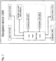
- Fig. 1 shows, in the form of a block diagram, an embodiment of a navigation device 1000 (in the following denoted as device 100) allowing a graphical correction of digitized map data according to the present invention.
- the device 1000 may be a built-in navigation device or a personal navigation device (PND).
- PND personal navigation device
- the embodiments are described in connection with a road network, the present disclosure can be also applied to networks of cycle paths.
- the device 1000 comprises a core functionality 1010 in the form of a central processing unit (CPU), a microprocessor, or in the form of a software module (SW module), an input unit 1020, an output unit 1030, a storage unit 1040, a detection unit 1050, a generation unit 1060, a position sensor 1070 and at least one communications interface 1080.
- a core functionality 1010 in the form of a central processing unit (CPU), a microprocessor, or in the form of a software module (SW module), an input unit 1020, an output unit 1030, a storage unit 1040, a detection unit 1050, a generation unit 1060, a position sensor 1070 and at least one communications interface 1080.
- CPU central processing unit
- SW module software module
- the at least one communications interface 1080 is configured to provide online connections with providers of map data and traffic information. Further, the at least one communications interface 1080 allows an online connection with other devices. Via the communications interface 1080 the device 1000 can receive updated map data and online traffic information. In addition, the device 1000 can share map data individually corrected by single users in accordance with the correction technique as described in detail below, by sending or receiving corrected map data over the interface 1080.
- the interface 1080 may be realized as a mixed hardware and software interface.
- the position sensor 1070 is configured to detect a current user position.
- the position sensor 1070 may be realized as absolute position sensor detecting a geographic latitude and longitude information reflecting thus the current geographic position of the user relative to a global geographic coordinate system.
- Such an absolute position sensor may detect signals from the GPS, Galileo, Glonass or other global positioning systems.
- the position sensor 1070 may be realized as relative position sensor detecting the travelled distance and headings of a vehicle during travel. In such a case the absolute position of a vehicle during travel may be determined by dead reckoning principles.
- the storage unit 1040 is configured to store map data in digitized form.
- the map data may be organized and structured according to a pre-defined data format in at least one database.
- the data in the database can be organized in accordance with the NDS format or assume any other format.
- the map data stored in the at least one database 1040 comprise at least route link data and associated shape point data indicative of the road geometry (i.e., the course) of road segments.
- the route link data may comprise a variety of route link attributes describing, for instance, road type, road classification, lane information, travel direction, predefined travel velocity, etc. of the road segments.
- the shape point data comprise longitude and latitude information as well as road segment shape information in order to fully describe the course of the road segments.
- the map data further comprise organized route node data indicative of road junctions of a road network.
- the route nodes mediate a connection between adjacent route links joining the route nodes as described in the introductory part above.
- Route node data and route link data can be organized in relational tables defining unambiguous relations between route link data, shape points and route node data (as well as other available navigation data, such as name data).
- route link data are organized to reference to the adjacent route nodes and the route nodes are organized to reference to all route links joining a node.
- shape points are organized to reference to the adjacent shape lines (road geometry connections between neighboring shape points).
- the map database may comprise further navigation data associated with enhanced navigation functionalities such as POI data, orthoimage data, TMC data, digital terrain data, and so on.
- the amount of data may depend on the map data supplier.
- the present graphical correction technique is also applicable for map databases comprising digital data associated with enhanced navigation applications.
- the input unit 1020 is designed to receive user input operations.
- Input operations may comprise user operations associated with the input of start points, end points or intermediate stops, or other relevant instructions or parameters required for specific route calculations.
- Input operations also comprise operations associated with map data manipulations, such as storing or deleting of map data, automatically modifying of map data by performing map data updates or by manually modifying map data according to the present invention.
- the input device may comprise a touch-sensitive screen, a key board, a mouse and/or voice recognition system for allowing speak inputs.
- the output unit 1030 is configured to visualize map data, to output guidance instructions, information about pre-calculated routes between a start and end point, and so one.
- the output device may comprise optical and acoustical components (such as a screen and loudspeaker) in order to provide optical and acoustical outputs.
- the units 1020 to 1080 are communicatively connected to the core functionality 1010 for information exchange.
- the detection unit 1050 and the determination unit 1060 can be realized as software sub-modules integrated in the core functionality 1010 or as hardware modules having appropriate software routines are in mutual communication with each other and with the core functionality 1010.
- the core functionality manages the data transfer between the corresponding modules 1020 to 1080.
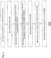
- Fig. 2 shows a flow diagram 101 of an method embodiment for correcting digitized map data stored in a map database, which method is now explained exemplarily on the basis of the device 1000 represented in Fig. 1 .
- the method as described in the following can be performed while a route guidance function is active. Alternatively, the method can be also performed when a route guidance is inactive or interrupted.
- the input 1020 and output unit 1030 are realized by a touch-sensitive screen.
- the principles of the claimed invention are not limited to a touch-sensitive screen (in the following simply denoted as screen 1020) and also work with other input devices such as a mouse.
- a road network of a specific geographic area of interest is visualized on the screen 1020 by retrieving from the database corresponding map data and subjecting them to a rendering procedure as commonly known by a person skilled in the art.
- the visualized interested geographic area is automatically set by the navigation device during route guidance. For instance, the device 1000 may adjust the visualized geographic area such that the entire pre-calculated route is visible. Alternatively, for resolution purposes the navigation device may restrict the visualized geographic area to a neighborhood of the detected current position during route guidance. Alternatively, or in addition thereto, the geographic position may be manually adjusted by the user.
- the device 1000 additionally visualizes the detected current user position relative to the visualized map data.
- the visualization of the current user position on the screen helps to localize the user's position on the visualized map.
- the user position is continuously updated by the device 1000 so that the user can continuously monitor on which road segment the user is currently travelling.
- the user can encounter situations in which the displayed road network or the outputted maneuver instructions do obviously not correspond to the course of the road the user is currently travelling (cf. also description below in conjunction with Figs. 3 and 4 ). Or the user recognizes that the visualized user position on the screen is jumped from one visualized map road to an adjacent map road.
- an editing mode function is implemented in the device 1000.
- the user selects the editing mode by, for instance, selecting a displayed editing mode function icon on the screen 1020.
- Other selection options of the editing mode are also conceivable.
- the core functionality 1010 activates the editing mode. The activation comprises activating the detection unit 1050 for determining the subsequent user inputs and activating the determination unit 1060 for tracking user manipulations.
- additional instructions guiding the user during the graphical data correction may be generated and outputted (for instance, in form of pop-up menus or sub-menus or windows containing prompts or instructions with regard to how modifications can be performed).
- the editing mode is graphically indicated by changing the colors of the visualized map or by indicating on the display that the editing mode is activated. Still further, upon activating the editing mode, the route guidance can be temporarily interrupted or continued.
- a subsequent third step S3 after the editing mode has been activated, the user is prompted to select at least one of one or more displayed road segments and junction nodes.
- the detection unit 1050 identifies the selected road segment. Based on the identified road segment selection, shape points and shape lines connecting adjacent shape points that are associated with the selected road segment are made visible on the screen 1020. The sequence of shape points and the shape lines between the shape points define the geometric road line of the road segment. Depending on the map data supplier shape points are available in distances between 10 to 40 meters.
- the displayed shape points and shape lines are now editable, i.e., modifiable.
- the user can also select a junction node (i.e. route node) for further corrections. In such a chase the displayed junction node is editable.
- a subsequent fourth step S4 the user can individually move each shape point of the selected road segment on the screen in order to correct the course of the selected road segment.
- the user can drag and drop each selected shape point individually to a new screen position.
- the user can move simultaneously two adjacent shape points over the screen by dragging and dropping a link line connecting the corresponding shape points.
- the user can group two or more shape points or the whole sequence of shape points for a common manipulation.
- the user can move, rotate, stretch and shrink the whole road segment resulting in a corresponding movement of the sequence of shape points representing the road geometry (i.e., the course) of the road segment.
- the determination unit 1060 tracks the position movement of the shape points on the screen and determines the new screen position of each modified shape point.
- the determination unit 1050 determines new geographic coordinates of each modified shape point on basis of the detected new screen positions.
- the generation of the new geographic coordinates is performed using a unique relationship between each screen position and the underlying displayed map data which represents a portion of a geographic area that is associated with unique latitude and longitude coordinates of a global (or local) coordinate system.
- the newly generated geographic coordinates for the moved shape points reflects the geographical displacement of the shape points of the selected road segment relative to the displayed map.
- the same moving, tracking and determining procedure as described for shape points applies for junction nodes.
- the core functionality 1010 After tracking the movement of the displayed shape points and/or junction nodes on the screen and assigning new geographic coordinates to the moved shape points, the core functionality 1010 prompts the user to confirm the performed corrections (sixth step S6).
- the determination unit 1050 stores in a subsequent seventh step S7 the new shape point data (new coordinate data for the moved points) in the database by overwriting the old geographic coordinates of the shape points or junction nodes. Since the course correction of road segments only involves a modification of stored shape point data of already available and organized shape points, the provided correction constitutes a "soft correction" that does not require modifications in the original map database structure.
- the map database structure before and after the modification are substantially the same, since data are only overwritten without affecting the size or the organization of the database elements (i.e., the relation between database elements such as links and nodes).
- Fig. 3a shows a situation in which a jump of the displayed current user position to a neighboring road is observed during route guidance.
- Fig. 3b shows a situation in which the road bending does obviously not correspond to the current road geometry.
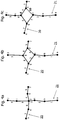
- Figs. 4a to 4c represent a situation in which an old cross-like junction has been transformed in a roundabout which was not updated so far by map data updates. In all these situations the user can manually adjust the map data to the up-to-date road geometry configuration without having to wait until the correct data adjustment have been met by updates.
- Fig. 3a shows a rendering 100 of a road network portion comprising two independent road portions 30, 40 (cf. thick line) on basis of the stored digitized map data.
- the real course of road 40 deviates from the digitized data and is illustrated by the dashed road course 40'.
- the digitized map data suggest an S-shaped course which is further away from the road 30 than the arch-shaped real road course.
- sequence of full triangles 11-14 showing the actual movement of the user position during route travel is first correctly matched to road 40 (positions 11, 12) on which the user is travelling, and suddenly jumps to the neighboring road 30 and remains matched to road 30 for a longer time (positions 13, 14 in Fig. 3a ).
- Such a jump is the result of an imprecise digitalization of the course of road 40, since the neighboring road 30 is closer to the position measured by the position sensor so that a matching algorithm chooses this road 30 for matching rather than the real road 40 on which the user is travelling.
- a re-routing is initiated associated with an output of wrong maneuver instructions which might disturb and confuse the user, since the road 30 is not part of the predetermined road.
- the jump to neighboring roads might confuse the user and leave the user in doubt as to which displayed road the currently driven road belongs to.
- the user can switch to the editing mode and perform the procedure as described in conjunction with the flow diagram 100 in Fig. 2 .
- the displayed user position can be used.
- the matching algorithm might be set to be inactive so that the real measured user position (indicated by the dashed triangles in Fig. 3a ) is displayed on the screen 1030 without matching it to a road.
- the user can observe the course of the visualized user position and use this position for manually correcting the course of the wrongly digitized road segment.
- the correction can be simply manually performed by selecting and dragging those shape points 32-35 (cf.
- shape points 31 to 36 which reflect the wrongly digitized course of the road segment to a screen position which corresponds to the geographic positions as indicated by the position sensor. Since a more complex manipulation on a touchscreen might be difficult to perform during travelling, the real geographic position measurements of the position sensor can be recorded during travel while the editing mode is active. The recorded user position data forms a trace which reflects the real course of the road segment. This trace can be loaded and displayed on the screen (also after travelling or when having a rest) and used as reference for manually correcting the wrongly digitized road segment data.
- the arrows in Fig. 3a illustrate how the shape points 32 to 35 have to be moved to screen positions (and map positions 32' to 35') in order to reproduce the real course of road 40.
- the road course correction according to the present invention can be fully performed by appropriately moving the shape points 32 to 35 relative to the displayed map such that they are reflecting the real road course.
- the sequence of new geographic coordinates of the shape points represents the new road course.
- the shape lines between adjacent shape points move automatically and need not to be corrected manually, since the shape lines only represent a connection between two adjacent shape points, to which they refer.
- the reference relation between the shape lines and shape points always remains unchanged by the graphical correction. In other words, the graphical manipulation effects that the geographic position of the manipulated shape points are changed but it does not affect the reference relation between shape lines and shape points.
- Fig. 3b shows another situation associated with incorrect digitalization of the course of a road segment 60.
- the picture shows the street course as perceived by the user.
- the inset picture on the bottom left shows a visualization of the road geometry derived from stored digitized map data.
- the triangle 61 denotes the current position of the user on the road. While the real road course shows a slight right bending, the visualized digitized data suggest a sharp right turn. There is obviously a major discrepancy between the real street course and the digitized road data which might cause trouble to the user.
- the predicted sharp right curve may make unsecure the user, since the user expects a steep turn which in reality does not exist.
- an instruction indicative of a sharp right turn may be outputted (user warning) which may additionally attract the user's attention to the upcoming maneuver.
- the user can again switch to the edit mode and perform the above-described manipulation by simply selecting and dragging the visualized shape points 62-67.
- the user will defuse the predicted sharp convex-shaped turn by simply dragging the shape points 63-65 inwards to the positions 63'-65' for smoothing the curve (cf. arrows illustrating the direction in which the shape point are displaced in order to smooth the sharp turn).
- the course correction or modification can be performed freehand and without reference imitating therefore qualitatively the course of the real road as noticed by the driver.
- the displayed user position as detected by the sensor can be used as reference for route course correction as described above.
- the shape points 62-67 are dragged to the map positions 63'-65' on which the position sensor position appears.
- a real image of the corresponding road segment if available, can be superimposed with the visualized road segment and used as correction reference.
- the shape points 62-67 are moved to correspond with the course as derivable form the superimposed image.
- Such an image can be retrieved from street image providers (Google street view) or provided by recording an image of the street course during travel.
- Figs. 4a to 4c another situation is illustrated in which the road network as predicted by the stored digitized map data does not comply with a real road network configuration.
- the situation concerns a transformation of a cross-like junction into a roundabout.
- Fig. 4a shows two crossing roads 20, 21 crossing at the junction node d.
- the road geometry of road 21 is described by the shape point sequence a, b, c, d, i, j and the corresponding shape lines 1, 2, 3, 8, 9 connecting each adjacent shape points of the sequence.
- Road 20 is described by the shape point sequence d, e, f, g, h and the shape lines 4, 5, 6, 7.
- the creation of a roundabout geometry can be easily performed by simply moving the shape point i of the road 21 in the shown new position of Fig. 4b (cf. shape point i indicated in bold).
- the already existing shape lines 3, 4, 6, 8 which are all referencing to the node d are changed to reference to the respective shape points c, g, i, e to form the link configuration as shown in Fig. 4b .
- the links lines 3, 4, 6, 8 are attributed to be a "roundabout link".
- Such change in the link attributes can be also performed graphically using a specific graphic attribute changing mechanism provided by the device 1000 in association with editable links in the editing mode.
- the graphic attribute changing mechanism comprises the displaying of a pop-up menu in response to a detected long-period selection operation for selecting one of the shape lines 3, 4, 6, 8.
- the pop-up menu the user can indicate for each shape line 3, 4, 6, 8 individually (for instance by setting a flag) that the lines 3, 4, 6, 8 are belonging to a roundabout.
- a roundabout is a geometric configuration which fundamentally differs from a cross-like junction, it can be created by simply using the existing links and shape point data. It is clear that the reverse transformation of a roundabout into a cross-like junction works in the same way. It is further noted that the transformation variant of Fig. 4b leaves unused the shape point d.
- This shape point can remain in the database as unreferenced data element or, alternatively, it can be graphically deleted in case the database allows such a deletion by users (i.e., is not configured to block an active deletion of database elements). Since shape point d represents an unreferenced data element, it does not further disturb navigation functionalities.
- a roundabout can be also graphically created from the displayed links and shape point data representing the cross-shaped junction of Fig. 1 by moving the shape point position of shape point d in a direction to the position of shape point i (new position of shape point d indicated in bold in Fig. 4c ).
- the movement of the position d affects that the shape line 8 is (automatically) shortened.
- the shape lines 4 and 6 already form an appropriate portion of the new roundabout configuration (i.e., first half of new roundabout defined by shape point sequence d, e, g and shape lines 4, 6).
- the other portion (i.e., second half) of the roundabout can be easily graphically generated by changing the reference of line 3 from shape point d to shape point g and by graphically introducing a new shape line 10 which references to shape points c and e in order to form an appropriate connection in-between (cf. dashed line in Fig. 4c ).
- a similar transformation result can be also achieved by moving shape point d in another direction.
- the manipulation of link attributes of the shape lines 3, 4, 6, 10 involved in forming the roundabout may be performed in the same way as described above in association with the roundabout generation of Fig. 4b .
- a roundabout does not necessarily require to generate and incorporate new map elements, such as shape points and links into the existing database. Rather, an appropriate manipulation of the position of existing shape points and an appropriate change in the link referencing is sufficient for transforming a cross-like junction configuration into a roundabout configuration and vice versa. Remaining unused shape points may remain as unreferenced data elements in the database.
- the advantage of manipulating only existing map data elements is that the database structure, especially the reference structure between the stored elements remains substantially unaffected by the modification avoiding therefore compromising of the data consistency and other data corruptions in the map database.
- new shape points and links can be graphically added or deleted ( Fig. 4c ). This can be done by graphically marking (for instance, by a long-period selection operation) shape points or links to be deleted or by selecting a screen position which corresponds to a map position of a selected road segment for adding a shape point and/or shape lines.
- shape points and/or shape lines are allowed to be added to the database the roundabout geometry can be reproduced more detailed.
- the addition of shape points or links increases the probability of data corrupttions or data inconsistencies in case the newly added elements are not reliably incorporated in the existing database structure by defining appropriate references between the new elements and the existing data elements.
- NDS stores map data in form of relational tables in a binary or textual format.
- the map data are organized in updatable sub-units which represent map data of a local geographic area of limited size (so called tiles as described above).
- Fig. 5 shows a NDS map database 1040 being accessible via a navigation software developer kit 200 (navigation SDK).
- the navigation SDK 200 comprises an interface 201 to navigation components (i.e., interface to navigation functionalities, like routing, map matching, map displaying, route guidance, etc.), an access layer 202 and an interface 203 to the NDS database.
- the access layer is in communicative connection with the interfaces 201, 203 and is designed to convert NDS data structures received from the interface 203 into data structures used by the navigation functionalities inside the navigation device 1000.
- the access layer 202 is designed to convert data received from the navigation functionalities over the interface 201 and to convert it to NDS data format.
- new routing data generated by the generation unit 1060 is transferred into the navigation SDK 200.
- the access layer 202 converts the modified data into NDS format (binary or textual format).
- the NDS converted data are then stored in the NDS database (cf. right path as indicated by the arrows in Fig. 5 ).
- the generated corrected routing data can replace the corresponding textual data.
- the conversion needs to extract the binary data, update the relevant parts and recreate the binary blob, and store it then back into the NDS database 1040.
- route links the mechanism also needs to take into account the connection to other route links during modification. The links need to get updated for allowing route calculations. This is obtained via the references to the route links.
Landscapes
- Engineering & Computer Science (AREA)
- Radar, Positioning & Navigation (AREA)
- Remote Sensing (AREA)
- Physics & Mathematics (AREA)
- Automation & Control Theory (AREA)
- General Physics & Mathematics (AREA)
- Geometry (AREA)
- Navigation (AREA)
- Instructional Devices (AREA)
Claims (15)
- Verfahren zur Korrektur von digitalisierten Kartendaten eines kreuzförmigen Knotenpunkts für einen Kreisverkehr, wobei die digitalisierten Kartendaten von einem Kartendatenlieferanten bereitgestellt und in einer Kartendatenbank (1040) eines Navigationsgeräts gespeichert werden, wobei die Kartendaten Routenplanungsdaten in Form von Routenverbindungen und formbeschreibenden Punkten umfassen, wobei jede Routenverbindung mit einer Abfolge von formbeschreibenden Punkten, die einen Verlauf eines Straßensegments (20, 21) zur Anzeige auf einem Bildschirm (100, 1030) darstellen, assoziiert ist, wobei das Verfahren folgende Schritte umfasst:- Detektieren eines ersten Benutzereingabevorgangs, der auf eine Auswahl eines Straßensegments (20, 21) an einem Knotenpunkt-Schnittpunkt (d) eines kreuzförmigen Knotenpunkts, der auf dem Bildschirm (100, 1030) angezeigt wird, hinweist, wobei das Straßensegment (20, 21) einer Routenverbindung der vom Kartendatenlieferanten bereitgestellten Kartendatenbank (1040) entspricht;- Anzeigen mindestens eines vorhandenen formbeschreibenden Punkts (a-j) der Abfolge von in der Kartendatenbank für das ausgewählte Straßensegment (20, 21) gespeicherten formbeschreibenden Punkten (3, 4, 6, 8) basierend auf den vom Kartendatenlieferanten bereitgestellten Kartendaten;- Detektieren mindestens eines zweiten Benutzereingabevorgangs, der auf eine grafische Veränderung des Verlaufs des ausgewählten Straßensegments (20, 21) auf dem Bildschirm (100, 1030) hinweist, wobei die grafische Veränderung eine Positionsverlagerung eines speziellen vorhandenen formbeschreibenden Punkts (i) neben dem Knotenpunkt-Schnittpunkt (d), der auf dem Bildschirm angezeigt wird, durch Verschieben des speziellen vorhandenen formbeschreibenden Punkts (i) von der angezeigten Bildschirmposition zu einer neuen Bildschirmposition hin umfasst;- Generieren korrigierter Routenplanungsdaten, die den veränderten Verlauf des ausgewählten Straßensegments (20, 21) widerspiegeln, basierend auf dem detektierten zweiten Benutzereingabevorgang;- Umwandeln des Knotenpunkt-Schnittpunkts (d) in ein unreferenziertes Datenelement, auf das keine formgebende Linie referenziert, in den Routenplanungsdaten;- Ändern vorhandener formgebender Linien (3, 4, 6, 8), die alle von einem daneben liegenden formbeschreibenden Punkt (c, e, g, i) aus auf den Knotenpunkt-Schnittpunkt (d) referenzieren, um vom jeweiligen daneben liegenden formbeschreibenden Punkt (c, e, g, i) aus auf einen jeweiligen benachbarten formbeschreibenden Punkt (c, e, g, i) der daneben liegenden formbeschreibenden Punkte (c, e, g, i) zu referenzieren; und- Speichern der korrigierten Routenplanungsdaten in der Kartendatenbank (1040) durch Überschreiben der vorhandenen Routenplanungsdaten des ausgewählten Straßensegments (30, 40, 60), ohne eine Struktur der ursprünglichen, vom Kartendatenlieferanten bereitgestellten Kartendatenbank (1040) zu modifizieren.
- Verfahren nach Anspruch 1, wobei die grafische Veränderung des Verlaufs des ausgewählten Straßensegments (20, 21) eine Positionsverlagerung eines einzelnen formbeschreibenden Punkts (a-j) umfasst.
- Verfahren nach Anspruch 1, wobei die grafische Veränderung des Verlaufs des ausgewählten Straßensegments (20, 21) eine gemeinsame Positionsverlagerung von zwei oder mehr formbeschreibenden Punkten (a-j) des Straßensegments (20, 21) durch Verschieben mindestens eines Abschnitts des angezeigten Straßensegments (20, 21) von der angezeigten Bildschirmposition zu einer neuen Bildschirmposition hin umfasst.
- Verfahren nach den Ansprüchen 1 bis 3, wobei das Detektieren der mindestens einen zweiten Benutzereingabe das Verfolgen des Ablaufs der Verlagerung jedes formbeschreibenden Punkts (a-j) und das Detektieren einer neuen Bildschirmposition für jeden verlagerten formbeschreibenden Punkt (a-j) umfasst.
- Verfahren nach Anspruch 2 oder 4, wobei der Schritt des Generierens das Umwandeln der detektierten neuen Bildschirmpositionen in neue geografische Koordinaten für die verlagerten formbeschreibenden Punkte umfasst.
- Verfahren nach einem der vorhergehenden Ansprüche, das ferner den anfänglichen Schritt des Umschaltens in einen Bearbeitungsmodus, der den Benutzer darauf hinweist, dass angezeigte Straßensegmente und/oder formbeschreibende Punkte auf dem Bildschirm (100, 1030) grafisch verändert werden können, umfasst.
- Verfahren nach Anspruch 6, wobei mit den angezeigten Straßensegmenten (20, 21) assoziierte formbeschreibende Punkte (a-j) angezeigt werden, wenn der Bearbeitungsmodus aktiviert ist.
- Verfahren nach Anspruch 6 oder 7, wobei der Bearbeitungsmodus aufrufbar ist, während eine Routenführung aktiv ist.
- Verfahren nach einem der vorhergehenden Ansprüche, das ferner das Bereitstellen einer Kartendatenkorrekturreferenz durch Anzeigen einer aktuellen Benutzerposition (11-14, 61) auf dem Bildschirm (100, 1030) ohne Abgleichen der Benutzerposition mit dem nächsten benachbarten Straßensegment des angezeigten Straßennetzes umfasst.
- Verfahren nach einem der vorhergehenden Ansprüche, das ferner das Bereitstellen einer Kartendatenkorrekturreferenz durch Einblenden von Realbildern in einem auf dem Bildschirm (100, 1030) angezeigten Straßennetzkartenabschnitt umfasst.
- Verfahren nach Anspruch 5, wobei das Überschreiben der vorhandenen Routenplanungsdaten das Ersetzen gespeicherter Daten zur geografischen Lage von formbeschreibenden Punkten durch die detektierten neuen Daten zur geografischen Lage der formbeschreibenden Punkte umfasst.
- Computerprogrammprodukt, das Programmcodeabschnitte zum Durchführen der Schritte nach einem der Ansprüche 1 bis 11, wenn das Computerprogrammprodukt in einem Navigationsgerät laufen gelassen wird, umfasst.
- Computerprogrammprodukt nach Anspruch 12, das in einem computerlesbaren Aufzeichnungsmedium gespeichert ist.
- Navigationsgerät (1000), das konfiguriert ist, um digitalisierte Kartendaten eines kreuzförmigen Knotenpunkts für einen Kreisverkehr zu korrigieren, wobei die digitalisierten Kartendaten von einem Kartendatenlieferanten bereitgestellt und in einer Kartendatenbank (1040) des Navigationsgeräts (1000) gespeichert werden, wobei die Kartendaten Routenplanungsdaten in Form von Routenverbindungen und formbeschreibenden Punkten umfassen, wobei jede Routenverbindung mit einer Abfolge von formbeschreibenden Punkten (a-j), die einen Verlauf eines Straßensegments (20, 21) zur Anzeige auf einem Bildschirm (100, 1030) darstellen, assoziiert ist, wobei das Gerät (1040) Folgendes umfasst:- eine Anzeigeeinheit (100, 1030) mit einem Bildschirm, die konfiguriert ist, um basierend auf den vom Kartendatenlieferanten bereitgestellten Kartendaten mindestens einen vorhandenen formbeschreibenden Punkt (a-j) der Abfolge von in der Kartendatenbank für das ausgewählte Routensegment (20, 21) gespeicherten formbeschreibenden Punkten (a-j) anzuzeigen;- eine Detektionseinheit (1050), die konfiguriert ist, um einen ersten Benutzereingabevorgang, der auf eine Auswahl eines Straßensegments (20, 21) an einem Knotenpunkt-Schnittpunkt (d) eines kreuzförmigen Knotenpunkts, der auf dem Bildschirm (100, 1030) angezeigt wird, zu detektieren, wobei das Straßensegment (20, 21) einer Routenverbindung der vom Kartendatenlieferanten bereitgestellten Kartendatenbank (1040) entspricht, und um mindestens einen zweiten Benutzereingabevorgang, der auf eine grafische Veränderung des Verlaufs des ausgewählten Straßensegments (20, 21) auf dem Bildschirm (100, 1030) hinweist, zu detektieren, wobei die grafische Veränderung eine Positionsverlagerung eines speziellen vorhandenen formbeschreibenden Punkts (i), der auf dem Bildschirm angezeigt wird, durch Verschieben des speziellen vorhandenen formbeschreibenden Punkts (i) von der angezeigten Bildschirmposition zu einer neuen Bildschirmposition hin umfasst;- eine Generierungseinheit (1060), die konfiguriert ist, um basierend auf dem detektierten zweiten Benutzereingabevorgang korrigierte Routenplanungsdaten, die den veränderten Verlauf des ausgewählten Straßensegments (20, 21) widerspiegeln, zu generieren, den Knotenpunkt-Schnittpunkt (d) in ein unreferenziertes Datenelement, auf das keine formgebende Linie referenziert, in den Routenplanungsdaten umzuwandeln und vorhandene formbeschreibende Linien (3, 4, 6, 8), die alle von einem daneben liegenden formbeschreibenden Punkt (c, e, g, i) aus auf den Knotenpunkt-Schnittpunkt (d) referenzieren, um vom jeweiligen daneben liegenden formbeschreibenden Punkt (c, e, g, i) aus auf einen jeweiligen benachbarten formbeschreibenden Punkt (c, e, g, i) der daneben liegenden formbeschreibenden Punkte (c, e, g, i) zu referenzieren, zu ändern; und- eine Speichereinheit (1040), die konfiguriert ist, um die korrigierten Routenplanungsdaten in der Kartendatenbank durch Überschreiben der vorhandenen Routenplanungsdaten des ausgewählten Straßensegments (20, 21) zu speichern, ohne eine Struktur der ursprünglichen, vom Kartendatenlieferanten bereitgestellten Kartendatenbank (1040) zu modifizieren.
- Gerät nach Anspruch 14, wobei der Bildschirm konfiguriert ist, um Straßensegmente (20, 21) und Straßenknotenpunkte basierend auf den gespeicherten Kartendaten anzuzeigen.
Priority Applications (4)
| Application Number | Priority Date | Filing Date | Title |
|---|---|---|---|
| EP13004489.4A EP2848892B1 (de) | 2013-09-13 | 2013-09-13 | Verfahren zur Korrektur von digitalisierten Kartendaten |
| US14/474,948 US9816826B2 (en) | 2013-09-13 | 2014-09-02 | Technique for correcting digitized map data |
| JP2014186662A JP2015055633A (ja) | 2013-09-13 | 2014-09-12 | デジタル化された地図データを修正するための技術 |
| CN201410469660.4A CN104457772B (zh) | 2013-09-13 | 2014-09-15 | 用于对数字化地图数据进行修正的技术 |
Applications Claiming Priority (1)
| Application Number | Priority Date | Filing Date | Title |
|---|---|---|---|
| EP13004489.4A EP2848892B1 (de) | 2013-09-13 | 2013-09-13 | Verfahren zur Korrektur von digitalisierten Kartendaten |
Publications (2)
| Publication Number | Publication Date |
|---|---|
| EP2848892A1 EP2848892A1 (de) | 2015-03-18 |
| EP2848892B1 true EP2848892B1 (de) | 2017-12-27 |
Family
ID=49230470
Family Applications (1)
| Application Number | Title | Priority Date | Filing Date |
|---|---|---|---|
| EP13004489.4A Active EP2848892B1 (de) | 2013-09-13 | 2013-09-13 | Verfahren zur Korrektur von digitalisierten Kartendaten |
Country Status (4)
| Country | Link |
|---|---|
| US (1) | US9816826B2 (de) |
| EP (1) | EP2848892B1 (de) |
| JP (1) | JP2015055633A (de) |
| CN (1) | CN104457772B (de) |
Families Citing this family (22)
| Publication number | Priority date | Publication date | Assignee | Title |
|---|---|---|---|---|
| DE102014015903B4 (de) * | 2014-10-29 | 2016-12-29 | Preh Car Connect Gmbh | Ausgeben einer Richtungsanweisung mit einer Navigationseinrichtung |
| JP6391507B2 (ja) * | 2015-03-18 | 2018-09-19 | アイシン・エィ・ダブリュ株式会社 | ナビゲーション装置、ナビゲーションプログラム、及びナビゲーション方法 |
| US9874451B2 (en) * | 2015-04-21 | 2018-01-23 | Here Global B.V. | Fresh hybrid routing independent of map version and provider |
| CN107543553B (zh) * | 2016-06-27 | 2020-12-15 | 阿里巴巴(中国)有限公司 | 一种兴趣点更新方法及装置 |
| US10415989B2 (en) * | 2016-09-06 | 2019-09-17 | International Business Machines Corporation | Navigation personalization through analysis of present and historical user data |
| US10036649B2 (en) | 2016-09-16 | 2018-07-31 | International Business Machines Corporation | Providing road guidance based on road attributes and directions |
| KR102441054B1 (ko) * | 2016-11-23 | 2022-09-06 | 현대자동차주식회사 | 차량의 경로 제어 장치 및 방법 |
| CN108007470B (zh) * | 2017-11-30 | 2021-06-25 | 深圳市隐湖科技有限公司 | 一种移动机器人地图文件格式和路径规划系统及其方法 |
| CN108153472A (zh) * | 2017-12-11 | 2018-06-12 | 上海博泰悦臻网络技术服务有限公司 | 导航路线修改方法、导航客户端及导航系统 |
| US10684132B2 (en) * | 2018-03-19 | 2020-06-16 | Here Global B.V. | Generation and update of a lane network graph model |
| CN109073387B (zh) * | 2018-07-20 | 2021-03-23 | 达闼机器人有限公司 | 一种多地图对齐的方法、装置、终端及存储介质 |
| CN109074638B (zh) * | 2018-07-23 | 2020-04-24 | 深圳前海达闼云端智能科技有限公司 | 融合建图方法、相关装置及计算机可读存储介质 |
| CN109945888B (zh) * | 2019-03-11 | 2021-03-16 | 百度在线网络技术(北京)有限公司 | 导航引导线的生成方法、装置及计算机设备 |
| CN110887495B (zh) * | 2019-11-28 | 2023-04-07 | 深圳市海力特科技有限责任公司 | 云平台实时路况在城市应急gis平台中应用的方法 |
| CN113138593A (zh) * | 2020-01-02 | 2021-07-20 | 苏州宝时得电动工具有限公司 | 自主机器人的地图创建方法、装置、设备及存储介质 |
| US11557053B2 (en) | 2020-02-07 | 2023-01-17 | International Business Machines Corporation | Deep learning to correct map and image features |
| WO2021188499A1 (en) * | 2020-03-17 | 2021-09-23 | Freeport Mcmoran Inc. | Methods and systems for determining vehicle travel routes |
| CN111896023B (zh) * | 2020-06-30 | 2022-08-09 | 汉海信息技术(上海)有限公司 | 导航路线生成方法、用户端、服务端、设备及存储介质 |
| CN111854791B (zh) * | 2020-07-21 | 2022-08-16 | 北京卡路里信息技术有限公司 | 一种运动轨迹确定方法、装置、终端设备和存储介质 |
| CN112097784A (zh) * | 2020-09-01 | 2020-12-18 | 武汉光庭信息技术股份有限公司 | 一种地图传感器地图匹配结果的验证方法及装置 |
| KR102609913B1 (ko) * | 2021-11-18 | 2023-12-05 | 주식회사 동성엔지니어링 | 멀티 에이전트 주행 시뮬레이션 데이터 생성 프로세스 제공 시스템 |
| CN114322992A (zh) * | 2022-01-18 | 2022-04-12 | 武汉元科技术有限公司 | 运动路径规划方法、生成方法、装置、设备及存储介质 |
Family Cites Families (18)
| Publication number | Priority date | Publication date | Assignee | Title |
|---|---|---|---|---|
| JPH0749993A (ja) * | 1993-08-05 | 1995-02-21 | Mitsubishi Electric Corp | ナビゲーション装置 |
| JP3275190B2 (ja) | 1993-11-19 | 2002-04-15 | 本田技研工業株式会社 | 地図情報再生装置 |
| JPH08271272A (ja) * | 1995-03-29 | 1996-10-18 | Matsushita Electric Ind Co Ltd | ナビゲーション装置 |
| JP2000230835A (ja) * | 1999-02-10 | 2000-08-22 | Daihatsu Motor Co Ltd | ナビゲーション装置及びその制御方法 |
| JP4543637B2 (ja) * | 2003-08-26 | 2010-09-15 | 三菱電機株式会社 | 地図情報処理装置 |
| JP4130441B2 (ja) | 2004-07-16 | 2008-08-06 | 三菱電機株式会社 | 地図情報処理装置 |
| JP4795206B2 (ja) | 2006-03-10 | 2011-10-19 | 三菱電機株式会社 | ナビゲーション装置 |
| GB2440958A (en) | 2006-08-15 | 2008-02-20 | Tomtom Bv | Method of correcting map data for use in navigation systems |
| DE112007003787B4 (de) * | 2006-09-21 | 2016-07-14 | Mitsubishi Electric Corp. | Karteninformations-Verarbeitungsvorrichtung |
| DE102008011001A1 (de) | 2007-08-25 | 2009-02-26 | Continental Teves Ag & Co. Ohg | Aktualisierung von digitalen Karten und Ortsbestimmung |
| WO2009030520A1 (de) | 2007-08-29 | 2009-03-12 | Continental Teves Ag & Co. Ohg | Dynamische aktualisierung von digitalen karten |
| JP4506855B2 (ja) * | 2008-03-05 | 2010-07-21 | 株式会社デンソー | カーナビゲーションシステム |
| CN101458092B (zh) | 2008-09-26 | 2011-08-10 | 深圳市路畅科技有限公司 | 自动导航系统中路口禁止转向标识的输入方法 |
| US20110098922A1 (en) | 2009-10-27 | 2011-04-28 | Visteon Global Technologies, Inc. | Path Predictive System And Method For Vehicles |
| CN102032910B (zh) | 2010-10-19 | 2013-01-02 | 清华大学 | 一种车载导航地图实时自排查的新路生成方法 |
| DE102011007267A1 (de) * | 2011-04-13 | 2012-10-18 | Robert Bosch Gmbh | Verfahren zum Betreiben eines Navigationssystems eines Fahrzeugs und Navigationssystem |
| US9110921B2 (en) * | 2011-06-21 | 2015-08-18 | Microsoft Technology Licensing, Llc | Map editing with little user input |
| ITTO20110850A1 (it) * | 2011-09-23 | 2013-03-24 | Sisvel Technology Srl | Metodo per gestire una mappa di un dispositivo di navigazione personale e relativo dispositivo |
-
2013
- 2013-09-13 EP EP13004489.4A patent/EP2848892B1/de active Active
-
2014
- 2014-09-02 US US14/474,948 patent/US9816826B2/en active Active
- 2014-09-12 JP JP2014186662A patent/JP2015055633A/ja active Pending
- 2014-09-15 CN CN201410469660.4A patent/CN104457772B/zh active Active
Non-Patent Citations (1)
| Title |
|---|
| None * |
Also Published As
| Publication number | Publication date |
|---|---|
| CN104457772B (zh) | 2017-06-23 |
| CN104457772A (zh) | 2015-03-25 |
| US9816826B2 (en) | 2017-11-14 |
| EP2848892A1 (de) | 2015-03-18 |
| US20150081217A1 (en) | 2015-03-19 |
| JP2015055633A (ja) | 2015-03-23 |
Similar Documents
| Publication | Publication Date | Title |
|---|---|---|
| EP2848892B1 (de) | Verfahren zur Korrektur von digitalisierten Kartendaten | |
| US10309797B2 (en) | User interface for displaying navigation information in a small display | |
| CN110375755B (zh) | 用于高度定制的交互式移动地图的解决方案 | |
| US10914607B2 (en) | Method, apparatus and computer program product for providing route guidance to multiple points of interest | |
| CN1668893B (zh) | 导航方法、用于导航系统的处理方法、地图数据管理装置、地图数据管理程序、以及计算机程序 | |
| JP5590950B2 (ja) | ナビゲーション装置および誘導経路探索方法 | |
| CN108253973B (zh) | 高精度地图和标准地图关联的方法及装置 | |
| US20090281720A1 (en) | Method and system for displaying navigation information on an electronic map | |
| JP2011252909A (ja) | ナビゲーション可能な位相図 | |
| EP3783315A1 (de) | Verfahren, vorrichtung und computerprogrammprodukt zur verwendung eines standortgraphen zur ermöglichung von natürlicher führung | |
| CN106030685A (zh) | 地图信息处理装置、地图信息处理方法及更新数据的调整方法 | |
| US8560224B2 (en) | Method and apparatus for establishing optimum route to intersection destination for navigation system | |
| CN115388876B (zh) | 智能可移动设备导航方法、装置、设备和存储介质 | |
| JP2015082045A (ja) | 地図データ配信システム、サーバ、及びナビゲーション装置 | |
| KR20200124622A (ko) | 실내 위치 확인 경로들 맵핑 툴 | |
| JP2007071749A (ja) | ナビゲーション装置 | |
| JP6351432B2 (ja) | 地図描画システムおよび地図描画方法 | |
| KR102944538B1 (ko) | 증강현실 뷰 내에서 3차원 지도를 표시하고, 3차원 지도 내의 객체와 관련된 정보를 포함하는 콘텐츠를 제공하는 방법 및 장치 | |
| KR102336775B1 (ko) | 테마경로 생성 장치 및 방법 | |
| JP2003173138A (ja) | 道路ネットワーク生成装置および方法 | |
| JP6164651B2 (ja) | 電子装置、経路探索方法および経路探索プログラム | |
| JP2008298613A (ja) | ナビゲーション装置および経路案内制御方法 | |
| JP6657582B2 (ja) | 経路探索システム、方法およびプログラム | |
| Maskrey et al. | Determining Location | |
| Paelke et al. | Dynamic maps for future navigation systems: agile design exploration of user interface concepts |
Legal Events
| Date | Code | Title | Description |
|---|---|---|---|
| PUAI | Public reference made under article 153(3) epc to a published international application that has entered the european phase |
Free format text: ORIGINAL CODE: 0009012 |
|
| 17P | Request for examination filed |
Effective date: 20140822 |
|
| AK | Designated contracting states |
Kind code of ref document: A1 Designated state(s): AL AT BE BG CH CY CZ DE DK EE ES FI FR GB GR HR HU IE IS IT LI LT LU LV MC MK MT NL NO PL PT RO RS SE SI SK SM TR |
|
| AX | Request for extension of the european patent |
Extension state: BA ME |
|
| 17Q | First examination report despatched |
Effective date: 20151006 |
|
| GRAP | Despatch of communication of intention to grant a patent |
Free format text: ORIGINAL CODE: EPIDOSNIGR1 |
|
| INTG | Intention to grant announced |
Effective date: 20170710 |
|
| GRAS | Grant fee paid |
Free format text: ORIGINAL CODE: EPIDOSNIGR3 |
|
| GRAA | (expected) grant |
Free format text: ORIGINAL CODE: 0009210 |
|
| AK | Designated contracting states |
Kind code of ref document: B1 Designated state(s): AL AT BE BG CH CY CZ DE DK EE ES FI FR GB GR HR HU IE IS IT LI LT LU LV MC MK MT NL NO PL PT RO RS SE SI SK SM TR |
|
| REG | Reference to a national code |
Ref country code: GB Ref legal event code: FG4D |
|
| REG | Reference to a national code |
Ref country code: CH Ref legal event code: EP |
|
| REG | Reference to a national code |
Ref country code: AT Ref legal event code: REF Ref document number: 958684 Country of ref document: AT Kind code of ref document: T Effective date: 20180115 |
|
| REG | Reference to a national code |
Ref country code: IE Ref legal event code: FG4D |
|
| REG | Reference to a national code |
Ref country code: DE Ref legal event code: R096 Ref document number: 602013031265 Country of ref document: DE |
|
| PG25 | Lapsed in a contracting state [announced via postgrant information from national office to epo] |
Ref country code: LT Free format text: LAPSE BECAUSE OF FAILURE TO SUBMIT A TRANSLATION OF THE DESCRIPTION OR TO PAY THE FEE WITHIN THE PRESCRIBED TIME-LIMIT Effective date: 20171227 Ref country code: NO Free format text: LAPSE BECAUSE OF FAILURE TO SUBMIT A TRANSLATION OF THE DESCRIPTION OR TO PAY THE FEE WITHIN THE PRESCRIBED TIME-LIMIT Effective date: 20180327 Ref country code: FI Free format text: LAPSE BECAUSE OF FAILURE TO SUBMIT A TRANSLATION OF THE DESCRIPTION OR TO PAY THE FEE WITHIN THE PRESCRIBED TIME-LIMIT Effective date: 20171227 |
|
| REG | Reference to a national code |
Ref country code: NL Ref legal event code: MP Effective date: 20171227 |
|
| REG | Reference to a national code |
Ref country code: LT Ref legal event code: MG4D |
|
| REG | Reference to a national code |
Ref country code: AT Ref legal event code: MK05 Ref document number: 958684 Country of ref document: AT Kind code of ref document: T Effective date: 20171227 |
|
| PG25 | Lapsed in a contracting state [announced via postgrant information from national office to epo] |
Ref country code: RS Free format text: LAPSE BECAUSE OF FAILURE TO SUBMIT A TRANSLATION OF THE DESCRIPTION OR TO PAY THE FEE WITHIN THE PRESCRIBED TIME-LIMIT Effective date: 20171227 Ref country code: BG Free format text: LAPSE BECAUSE OF FAILURE TO SUBMIT A TRANSLATION OF THE DESCRIPTION OR TO PAY THE FEE WITHIN THE PRESCRIBED TIME-LIMIT Effective date: 20180327 Ref country code: HR Free format text: LAPSE BECAUSE OF FAILURE TO SUBMIT A TRANSLATION OF THE DESCRIPTION OR TO PAY THE FEE WITHIN THE PRESCRIBED TIME-LIMIT Effective date: 20171227 Ref country code: GR Free format text: LAPSE BECAUSE OF FAILURE TO SUBMIT A TRANSLATION OF THE DESCRIPTION OR TO PAY THE FEE WITHIN THE PRESCRIBED TIME-LIMIT Effective date: 20180328 Ref country code: LV Free format text: LAPSE BECAUSE OF FAILURE TO SUBMIT A TRANSLATION OF THE DESCRIPTION OR TO PAY THE FEE WITHIN THE PRESCRIBED TIME-LIMIT Effective date: 20171227 |
|
| PG25 | Lapsed in a contracting state [announced via postgrant information from national office to epo] |
Ref country code: NL Free format text: LAPSE BECAUSE OF FAILURE TO SUBMIT A TRANSLATION OF THE DESCRIPTION OR TO PAY THE FEE WITHIN THE PRESCRIBED TIME-LIMIT Effective date: 20171227 |
|
| PG25 | Lapsed in a contracting state [announced via postgrant information from national office to epo] |
Ref country code: ES Free format text: LAPSE BECAUSE OF FAILURE TO SUBMIT A TRANSLATION OF THE DESCRIPTION OR TO PAY THE FEE WITHIN THE PRESCRIBED TIME-LIMIT Effective date: 20171227 Ref country code: CZ Free format text: LAPSE BECAUSE OF FAILURE TO SUBMIT A TRANSLATION OF THE DESCRIPTION OR TO PAY THE FEE WITHIN THE PRESCRIBED TIME-LIMIT Effective date: 20171227 Ref country code: CY Free format text: LAPSE BECAUSE OF FAILURE TO SUBMIT A TRANSLATION OF THE DESCRIPTION OR TO PAY THE FEE WITHIN THE PRESCRIBED TIME-LIMIT Effective date: 20171227 Ref country code: EE Free format text: LAPSE BECAUSE OF FAILURE TO SUBMIT A TRANSLATION OF THE DESCRIPTION OR TO PAY THE FEE WITHIN THE PRESCRIBED TIME-LIMIT Effective date: 20171227 Ref country code: SK Free format text: LAPSE BECAUSE OF FAILURE TO SUBMIT A TRANSLATION OF THE DESCRIPTION OR TO PAY THE FEE WITHIN THE PRESCRIBED TIME-LIMIT Effective date: 20171227 |
|
| PG25 | Lapsed in a contracting state [announced via postgrant information from national office to epo] |
Ref country code: RO Free format text: LAPSE BECAUSE OF FAILURE TO SUBMIT A TRANSLATION OF THE DESCRIPTION OR TO PAY THE FEE WITHIN THE PRESCRIBED TIME-LIMIT Effective date: 20171227 Ref country code: IS Free format text: LAPSE BECAUSE OF FAILURE TO SUBMIT A TRANSLATION OF THE DESCRIPTION OR TO PAY THE FEE WITHIN THE PRESCRIBED TIME-LIMIT Effective date: 20180427 Ref country code: SM Free format text: LAPSE BECAUSE OF FAILURE TO SUBMIT A TRANSLATION OF THE DESCRIPTION OR TO PAY THE FEE WITHIN THE PRESCRIBED TIME-LIMIT Effective date: 20171227 Ref country code: IT Free format text: LAPSE BECAUSE OF FAILURE TO SUBMIT A TRANSLATION OF THE DESCRIPTION OR TO PAY THE FEE WITHIN THE PRESCRIBED TIME-LIMIT Effective date: 20171227 Ref country code: AT Free format text: LAPSE BECAUSE OF FAILURE TO SUBMIT A TRANSLATION OF THE DESCRIPTION OR TO PAY THE FEE WITHIN THE PRESCRIBED TIME-LIMIT Effective date: 20171227 Ref country code: PL Free format text: LAPSE BECAUSE OF FAILURE TO SUBMIT A TRANSLATION OF THE DESCRIPTION OR TO PAY THE FEE WITHIN THE PRESCRIBED TIME-LIMIT Effective date: 20171227 |
|
| REG | Reference to a national code |
Ref country code: FR Ref legal event code: PLFP Year of fee payment: 6 |
|
| REG | Reference to a national code |
Ref country code: DE Ref legal event code: R097 Ref document number: 602013031265 Country of ref document: DE |
|
| PLBE | No opposition filed within time limit |
Free format text: ORIGINAL CODE: 0009261 |
|
| STAA | Information on the status of an ep patent application or granted ep patent |
Free format text: STATUS: NO OPPOSITION FILED WITHIN TIME LIMIT |
|
| PG25 | Lapsed in a contracting state [announced via postgrant information from national office to epo] |
Ref country code: DK Free format text: LAPSE BECAUSE OF FAILURE TO SUBMIT A TRANSLATION OF THE DESCRIPTION OR TO PAY THE FEE WITHIN THE PRESCRIBED TIME-LIMIT Effective date: 20171227 |
|
| 26N | No opposition filed |
Effective date: 20180928 |
|
| PG25 | Lapsed in a contracting state [announced via postgrant information from national office to epo] |
Ref country code: SI Free format text: LAPSE BECAUSE OF FAILURE TO SUBMIT A TRANSLATION OF THE DESCRIPTION OR TO PAY THE FEE WITHIN THE PRESCRIBED TIME-LIMIT Effective date: 20171227 |
|
| PG25 | Lapsed in a contracting state [announced via postgrant information from national office to epo] |
Ref country code: MC Free format text: LAPSE BECAUSE OF FAILURE TO SUBMIT A TRANSLATION OF THE DESCRIPTION OR TO PAY THE FEE WITHIN THE PRESCRIBED TIME-LIMIT Effective date: 20171227 |
|
| REG | Reference to a national code |
Ref country code: CH Ref legal event code: PL |
|
| GBPC | Gb: european patent ceased through non-payment of renewal fee |
Effective date: 20180913 |
|
| REG | Reference to a national code |
Ref country code: BE Ref legal event code: MM Effective date: 20180930 |
|
| REG | Reference to a national code |
Ref country code: IE Ref legal event code: MM4A |
|
| PG25 | Lapsed in a contracting state [announced via postgrant information from national office to epo] |
Ref country code: LU Free format text: LAPSE BECAUSE OF NON-PAYMENT OF DUE FEES Effective date: 20180913 |
|
| PG25 | Lapsed in a contracting state [announced via postgrant information from national office to epo] |
Ref country code: IE Free format text: LAPSE BECAUSE OF NON-PAYMENT OF DUE FEES Effective date: 20180913 |
|
| PG25 | Lapsed in a contracting state [announced via postgrant information from national office to epo] |
Ref country code: BE Free format text: LAPSE BECAUSE OF NON-PAYMENT OF DUE FEES Effective date: 20180930 Ref country code: LI Free format text: LAPSE BECAUSE OF NON-PAYMENT OF DUE FEES Effective date: 20180930 Ref country code: CH Free format text: LAPSE BECAUSE OF NON-PAYMENT OF DUE FEES Effective date: 20180930 |
|
| PG25 | Lapsed in a contracting state [announced via postgrant information from national office to epo] |
Ref country code: GB Free format text: LAPSE BECAUSE OF NON-PAYMENT OF DUE FEES Effective date: 20180913 |
|
| PG25 | Lapsed in a contracting state [announced via postgrant information from national office to epo] |
Ref country code: MT Free format text: LAPSE BECAUSE OF NON-PAYMENT OF DUE FEES Effective date: 20180913 |
|
| PG25 | Lapsed in a contracting state [announced via postgrant information from national office to epo] |
Ref country code: TR Free format text: LAPSE BECAUSE OF FAILURE TO SUBMIT A TRANSLATION OF THE DESCRIPTION OR TO PAY THE FEE WITHIN THE PRESCRIBED TIME-LIMIT Effective date: 20171227 |
|
| PG25 | Lapsed in a contracting state [announced via postgrant information from national office to epo] |
Ref country code: PT Free format text: LAPSE BECAUSE OF FAILURE TO SUBMIT A TRANSLATION OF THE DESCRIPTION OR TO PAY THE FEE WITHIN THE PRESCRIBED TIME-LIMIT Effective date: 20171227 Ref country code: HU Free format text: LAPSE BECAUSE OF FAILURE TO SUBMIT A TRANSLATION OF THE DESCRIPTION OR TO PAY THE FEE WITHIN THE PRESCRIBED TIME-LIMIT; INVALID AB INITIO Effective date: 20130913 |
|
| PG25 | Lapsed in a contracting state [announced via postgrant information from national office to epo] |
Ref country code: MK Free format text: LAPSE BECAUSE OF NON-PAYMENT OF DUE FEES Effective date: 20171227 Ref country code: SE Free format text: LAPSE BECAUSE OF FAILURE TO SUBMIT A TRANSLATION OF THE DESCRIPTION OR TO PAY THE FEE WITHIN THE PRESCRIBED TIME-LIMIT Effective date: 20171227 |
|
| PG25 | Lapsed in a contracting state [announced via postgrant information from national office to epo] |
Ref country code: AL Free format text: LAPSE BECAUSE OF FAILURE TO SUBMIT A TRANSLATION OF THE DESCRIPTION OR TO PAY THE FEE WITHIN THE PRESCRIBED TIME-LIMIT Effective date: 20171227 |
|
| REG | Reference to a national code |
Ref country code: DE Ref legal event code: R084 Ref document number: 602013031265 Country of ref document: DE |
|
| P01 | Opt-out of the competence of the unified patent court (upc) registered |
Effective date: 20230522 |
|
| PGFP | Annual fee paid to national office [announced via postgrant information from national office to epo] |
Ref country code: DE Payment date: 20250930 Year of fee payment: 13 |
|
| PGFP | Annual fee paid to national office [announced via postgrant information from national office to epo] |
Ref country code: FR Payment date: 20250922 Year of fee payment: 13 |