EP2853577A1 - Procédé de fabrication de liquide de dispersion de luminophore et procédé de fabrication de dispositif de diode électroluminescente - Google Patents
Procédé de fabrication de liquide de dispersion de luminophore et procédé de fabrication de dispositif de diode électroluminescente Download PDFInfo
- Publication number
- EP2853577A1 EP2853577A1 EP13879580.2A EP13879580A EP2853577A1 EP 2853577 A1 EP2853577 A1 EP 2853577A1 EP 13879580 A EP13879580 A EP 13879580A EP 2853577 A1 EP2853577 A1 EP 2853577A1
- Authority
- EP
- European Patent Office
- Prior art keywords
- dispersion liquid
- phosphor
- particles
- phosphor particles
- viscosity
- Prior art date
- Legal status (The legal status is an assumption and is not a legal conclusion. Google has not performed a legal analysis and makes no representation as to the accuracy of the status listed.)
- Withdrawn
Links
Images
Classifications
-
- C—CHEMISTRY; METALLURGY
- C09—DYES; PAINTS; POLISHES; NATURAL RESINS; ADHESIVES; COMPOSITIONS NOT OTHERWISE PROVIDED FOR; APPLICATIONS OF MATERIALS NOT OTHERWISE PROVIDED FOR
- C09K—MATERIALS FOR MISCELLANEOUS APPLICATIONS, NOT PROVIDED FOR ELSEWHERE
- C09K11/00—Luminescent materials, e.g. electroluminescent or chemiluminescent
- C09K11/02—Use of particular materials as binders, particle coatings or suspension media therefor
-
- C—CHEMISTRY; METALLURGY
- C09—DYES; PAINTS; POLISHES; NATURAL RESINS; ADHESIVES; COMPOSITIONS NOT OTHERWISE PROVIDED FOR; APPLICATIONS OF MATERIALS NOT OTHERWISE PROVIDED FOR
- C09K—MATERIALS FOR MISCELLANEOUS APPLICATIONS, NOT PROVIDED FOR ELSEWHERE
- C09K11/00—Luminescent materials, e.g. electroluminescent or chemiluminescent
- C09K11/08—Luminescent materials, e.g. electroluminescent or chemiluminescent containing inorganic luminescent materials
- C09K11/77—Luminescent materials, e.g. electroluminescent or chemiluminescent containing inorganic luminescent materials containing rare earth metals
- C09K11/7766—Luminescent materials, e.g. electroluminescent or chemiluminescent containing inorganic luminescent materials containing rare earth metals containing two or more rare earth metals
-
- C—CHEMISTRY; METALLURGY
- C09—DYES; PAINTS; POLISHES; NATURAL RESINS; ADHESIVES; COMPOSITIONS NOT OTHERWISE PROVIDED FOR; APPLICATIONS OF MATERIALS NOT OTHERWISE PROVIDED FOR
- C09K—MATERIALS FOR MISCELLANEOUS APPLICATIONS, NOT PROVIDED FOR ELSEWHERE
- C09K11/00—Luminescent materials, e.g. electroluminescent or chemiluminescent
- C09K11/08—Luminescent materials, e.g. electroluminescent or chemiluminescent containing inorganic luminescent materials
- C09K11/77—Luminescent materials, e.g. electroluminescent or chemiluminescent containing inorganic luminescent materials containing rare earth metals
- C09K11/7715—Luminescent materials, e.g. electroluminescent or chemiluminescent containing inorganic luminescent materials containing rare earth metals containing cerium
- C09K11/7721—Aluminates
-
- C—CHEMISTRY; METALLURGY
- C09—DYES; PAINTS; POLISHES; NATURAL RESINS; ADHESIVES; COMPOSITIONS NOT OTHERWISE PROVIDED FOR; APPLICATIONS OF MATERIALS NOT OTHERWISE PROVIDED FOR
- C09K—MATERIALS FOR MISCELLANEOUS APPLICATIONS, NOT PROVIDED FOR ELSEWHERE
- C09K11/00—Luminescent materials, e.g. electroluminescent or chemiluminescent
- C09K11/08—Luminescent materials, e.g. electroluminescent or chemiluminescent containing inorganic luminescent materials
- C09K11/77—Luminescent materials, e.g. electroluminescent or chemiluminescent containing inorganic luminescent materials containing rare earth metals
- C09K11/7766—Luminescent materials, e.g. electroluminescent or chemiluminescent containing inorganic luminescent materials containing rare earth metals containing two or more rare earth metals
- C09K11/7774—Aluminates
-
- H—ELECTRICITY
- H05—ELECTRIC TECHNIQUES NOT OTHERWISE PROVIDED FOR
- H05B—ELECTRIC HEATING; ELECTRIC LIGHT SOURCES NOT OTHERWISE PROVIDED FOR; CIRCUIT ARRANGEMENTS FOR ELECTRIC LIGHT SOURCES, IN GENERAL
- H05B33/00—Electroluminescent light sources
- H05B33/12—Light sources with substantially two-dimensional [2D] radiating surfaces
- H05B33/14—Light sources with substantially two-dimensional [2D] radiating surfaces characterised by the chemical or physical composition or the arrangement of the electroluminescent material, or by the simultaneous addition of the electroluminescent material in or onto the light source
-
- H—ELECTRICITY
- H10—SEMICONDUCTOR DEVICES; ELECTRIC SOLID-STATE DEVICES NOT OTHERWISE PROVIDED FOR
- H10H—INORGANIC LIGHT-EMITTING SEMICONDUCTOR DEVICES HAVING POTENTIAL BARRIERS
- H10H20/00—Individual inorganic light-emitting semiconductor devices having potential barriers, e.g. light-emitting diodes [LED]
- H10H20/01—Manufacture or treatment
- H10H20/036—Manufacture or treatment of packages
- H10H20/0361—Manufacture or treatment of packages of wavelength conversion means
-
- H—ELECTRICITY
- H10—SEMICONDUCTOR DEVICES; ELECTRIC SOLID-STATE DEVICES NOT OTHERWISE PROVIDED FOR
- H10H—INORGANIC LIGHT-EMITTING SEMICONDUCTOR DEVICES HAVING POTENTIAL BARRIERS
- H10H20/00—Individual inorganic light-emitting semiconductor devices having potential barriers, e.g. light-emitting diodes [LED]
- H10H20/01—Manufacture or treatment
- H10H20/036—Manufacture or treatment of packages
- H10H20/0362—Manufacture or treatment of packages of encapsulations
-
- H—ELECTRICITY
- H10—SEMICONDUCTOR DEVICES; ELECTRIC SOLID-STATE DEVICES NOT OTHERWISE PROVIDED FOR
- H10H—INORGANIC LIGHT-EMITTING SEMICONDUCTOR DEVICES HAVING POTENTIAL BARRIERS
- H10H20/00—Individual inorganic light-emitting semiconductor devices having potential barriers, e.g. light-emitting diodes [LED]
- H10H20/062—Light-emitting semiconductor devices having field effect type light-emitting regions, e.g. light-emitting High-Electron Mobility Transistors
-
- H—ELECTRICITY
- H10—SEMICONDUCTOR DEVICES; ELECTRIC SOLID-STATE DEVICES NOT OTHERWISE PROVIDED FOR
- H10H—INORGANIC LIGHT-EMITTING SEMICONDUCTOR DEVICES HAVING POTENTIAL BARRIERS
- H10H20/00—Individual inorganic light-emitting semiconductor devices having potential barriers, e.g. light-emitting diodes [LED]
- H10H20/80—Constructional details
- H10H20/85—Packages
- H10H20/851—Wavelength conversion means
-
- H—ELECTRICITY
- H10—SEMICONDUCTOR DEVICES; ELECTRIC SOLID-STATE DEVICES NOT OTHERWISE PROVIDED FOR
- H10H—INORGANIC LIGHT-EMITTING SEMICONDUCTOR DEVICES HAVING POTENTIAL BARRIERS
- H10H20/00—Individual inorganic light-emitting semiconductor devices having potential barriers, e.g. light-emitting diodes [LED]
- H10H20/80—Constructional details
- H10H20/85—Packages
- H10H20/851—Wavelength conversion means
- H10H20/8511—Wavelength conversion means characterised by their material, e.g. binder
- H10H20/8512—Wavelength conversion materials
-
- H—ELECTRICITY
- H10—SEMICONDUCTOR DEVICES; ELECTRIC SOLID-STATE DEVICES NOT OTHERWISE PROVIDED FOR
- H10H—INORGANIC LIGHT-EMITTING SEMICONDUCTOR DEVICES HAVING POTENTIAL BARRIERS
- H10H20/00—Individual inorganic light-emitting semiconductor devices having potential barriers, e.g. light-emitting diodes [LED]
- H10H20/80—Constructional details
- H10H20/85—Packages
- H10H20/851—Wavelength conversion means
- H10H20/8515—Wavelength conversion means not being in contact with the bodies
-
- H—ELECTRICITY
- H10—SEMICONDUCTOR DEVICES; ELECTRIC SOLID-STATE DEVICES NOT OTHERWISE PROVIDED FOR
- H10H—INORGANIC LIGHT-EMITTING SEMICONDUCTOR DEVICES HAVING POTENTIAL BARRIERS
- H10H20/00—Individual inorganic light-emitting semiconductor devices having potential barriers, e.g. light-emitting diodes [LED]
- H10H20/80—Constructional details
- H10H20/85—Packages
- H10H20/852—Encapsulations
- H10H20/854—Encapsulations characterised by their material, e.g. epoxy or silicone resins
-
- H—ELECTRICITY
- H10—SEMICONDUCTOR DEVICES; ELECTRIC SOLID-STATE DEVICES NOT OTHERWISE PROVIDED FOR
- H10W—GENERIC PACKAGES, INTERCONNECTIONS, CONNECTORS OR OTHER CONSTRUCTIONAL DETAILS OF DEVICES COVERED BY CLASS H10
- H10W72/00—Interconnections or connectors in packages
- H10W72/01—Manufacture or treatment
- H10W72/015—Manufacture or treatment of bond wires
- H10W72/01515—Forming coatings
-
- H—ELECTRICITY
- H10—SEMICONDUCTOR DEVICES; ELECTRIC SOLID-STATE DEVICES NOT OTHERWISE PROVIDED FOR
- H10W—GENERIC PACKAGES, INTERCONNECTIONS, CONNECTORS OR OTHER CONSTRUCTIONAL DETAILS OF DEVICES COVERED BY CLASS H10
- H10W72/00—Interconnections or connectors in packages
- H10W72/071—Connecting or disconnecting
- H10W72/075—Connecting or disconnecting of bond wires
-
- H—ELECTRICITY
- H10—SEMICONDUCTOR DEVICES; ELECTRIC SOLID-STATE DEVICES NOT OTHERWISE PROVIDED FOR
- H10W—GENERIC PACKAGES, INTERCONNECTIONS, CONNECTORS OR OTHER CONSTRUCTIONAL DETAILS OF DEVICES COVERED BY CLASS H10
- H10W74/00—Encapsulations, e.g. protective coatings
Definitions
- the present invention relates to a method of producing a phosphor dispersion liquid, and a method of manufacturing an LED device.
- a white LED device with a yellow phosphor such as YAG being disposed in the vicinity of a gallium nitride (GaN)-based blue LED (Light-Emitting Diode) element In this white LED device, blue light emitted by the blue LED element and yellow light emanated by the phosphor upon receipt of blue light are mixed to obtain white light. Further, there has also been developed a white LED device in which blue light emitted by a blue LED element and red light, green light, or the like emanated by a phosphor upon receipt of blue light are mixed to obtain white light.
- an encapsulating member in which phosphor particles are dispersed in a transparent resin.
- the specific gravity of phosphor particles contained in the encapsulating member is greater than the specific gravity of the transparent resin. Therefore, there has been a problem in which, at the time of the formation of the encapsulating member, phosphor particles easily settle before curing of the transparent resin, causing the concentration of the phosphor not to be uniform inside the encapsulating member. If the concentration of the phosphor is not uniform, the chromaticity of irradiation light of an LED device is hard to fall within a desired range.
- a silicone resin with high viscosity is adopted as an encapsulating resin, making it difficult for phosphor particles to settle (PTL 1). Further, it is also proposed that settling of the phosphor particles is suppressed by: adding a laminar clay compound and an organic cation to an encapsulating resin (PTL 2); and by adding silicone microparticles to an encapsulating resin (PTL 3).
- any of the techniques of PTLs 1 to 3 ends up encapsulating phosphor particles with resin. Therefore, there have been a problem in which light and heat from an LED element cause an encapsulating resin to be easily colored and deteriorated.
- a phosphor dispersion liquid containing phosphor particles is applied onto an LED element to form a phosphor particle layer; and thereafter 2) a solution containing a ceramic precursor is applied onto the phosphor particle layer to bind the phosphor particle layer with a translucent ceramic binder. According to this method, there is less risk that a phosphor dispersion liquid or a solution containing a ceramic precursor may be gelated during storage.
- a phosphor dispersion liquid free from a binder component has lower viscosity, causing phosphor particles to easily settle over time.
- phosphor particles and laminar clay mineral particles are added to a solvent, and these are stirred and mixed with a relatively high shearing force.
- phosphor particles and laminar clay mineral particles are dispersed uniformly, allowing the phosphor particles to be hard to settle.
- An object of the present invention is to provide a method of producing a phosphor dispersion liquid with phosphor particles being hard to settle without deteriorating phosphor particles.
- a first aspect of the present invention relates to methods of producing a phosphor dispersion liquid set forth below.
- laminar clay minerals and phosphor particles can be uniformly dispersed, and phosphor particles are hard to settle in a phosphor dispersion liquid to be obtained.
- a shearing force applied to the phosphor particles can be decreased, so that the deterioration of phosphor particles at the time of preparing the phosphor dispersion liquid can be suppressed.
- a phosphor dispersion liquid containing phosphor particles, laminar clay mineral particles, oxide microparticles, and a solvent is prepared.
- components other than phosphor particles are mixed earlier, and phosphor particles are mixed afterward.
- the phosphor dispersion liquid is prepared via two steps set forth below.
- a step of housing in a shipping container the first dispersion liquid may be carried out where necessary, after the step of preparing the first dispersion liquid and before mixing the phosphor particles.
- a liquid in which all the phosphor particles, laminar clay mineral particles, a solvent, and the like are mixed has been stirred and mixed. At that time, if stirring and mixing are insufficient, then dispersion of phosphor particles and laminar clay mineral particles becomes non-uniform, causing phosphor particles to settle over time.
- stirring and mixing are insufficient, then dispersion of phosphor particles and laminar clay mineral particles becomes non-uniform, causing phosphor particles to settle over time.
- the process of producing phosphor dispersion liquid is divided into two steps. That is, a liquid mixture of materials other than phosphors (a laminar clay compound, oxide microparticles, and a solvent) is mixed to prepare a first dispersion liquid.
- the liquid mixture does not contain phosphor particles. Accordingly, the respective components can be mixed using a higher shearing force, enabling to prepare a first dispersion liquid in which laminar clay mineral particles and oxide microparticles are uniformly dispersed.
- Phosphor particles are then mixed into the first dispersion liquid.
- the phosphor particles have affinity with the laminar clay mineral particles. Therefore, when phosphor particles are mixed into the first dispersion liquid in which the laminar clay mineral particles are uniformly dispersed, the phosphor particles are attracted to the laminar clay mineral particles, allowing the phosphor particles to be uniformly dispersed. That is, even without applying a higher shearing force, a phosphor dispersion liquid in which phosphor particles are uniformly dispersed can be prepared. Further, in the phosphor dispersion liquid to be obtained, laminar clay mineral particles and phosphor particles are uniformly dispersed, allowing the phosphor particles to be hard to settle even if it is stored for a long period of time.
- first dispersion liquid In the step of preparing the first dispersion liquid, laminar clay mineral particles, oxide microparticles, and a solvent are mixed to prepare a first dispersion liquid.
- a laminar clay mineral particle is a particle composed of clay minerals having a laminar structure.
- the laminar clay mineral particle assumes a plate-like shape. Therefore, when laminar clay mineral particles are contained, the viscosity of the first dispersion liquid to be obtained, and thus that of the phosphor dispersion liquid are increased. Further, as mentioned above, the laminar clay mineral particles have a higher affinity with phosphor particles. Accordingly, when the laminar clay mineral particles are uniformly dispersed in the first dispersion liquid, the dispersibility of the phosphor particles is increased.
- laminar clay minerals examples include a laminar silicate mineral, imogolite, allophane, and the like.
- the laminar silicate mineral is preferably a swellable clay mineral having a mica structure, a kaolinite structure or a smectite structure, and particularly preferably a swellable clay mineral having a smectite structure with good swelling property. Since the swellable clay mineral particles form a card-house structure in a phosphor-containing liquid, the viscosity thereof is increased by allowing only a small amount thereof to be contained in the first dispersion liquid.
- laminar clay minerals include natural or synthetic smectite clay minerals such as hectorite, saponite, stevensite, beidellite, montmorillonite, nontronite, bentonite and laponite, swellable mica clay minerals such as Na tetrasilicicfluorinemica, Li tetrasilicicfluorinemica, Na fluorine taeniolite and Li fluorine taeniolite, non-swellable mica clay minerals such as muscovite, phlogopite, fluor-phlogopite, sericite and potassium tetrasilisic mica, and vermiculite or kaolinite, or mixtures thereof.
- smectite clay minerals such as hectorite, saponite, stevensite, beidellite, montmorillonite, nontronite, bentonite and laponite
- swellable mica clay minerals such as Na tetrasilicicflu
- laminar clay mineral particles examples include: Laponite XLG (synthetic hectorite analogue available from LaPorte Co., UK); Laponite RD (synthetic hectorite analogue available from LaPorte Co., UK); Samabisu (synthetic hectorite analogue available from Henkel, Germany); Sumecton SA-1 (saponite analogue available from KUNIMINE Industry Co., Ltd.); BEN-GEL (natural bentonite available from Hojun Corporation); Kunipia F (natural montmorillonite available from KUNIMINE Industry Co., Ltd.); Veegum (natural hectorite available from Vanderbilt Co., Ltd, US); Daimonaito (synthetic swellable mica available from Topy Industries Ltd.); Somasif (synthetic swellable mica available from CO-OP CHEMICAL CO., LTD.); SWN (synthetic smectite
- the laminar clay mineral particles may be those the surface of which is modified (surface-treated) with an ammonium salt or the like. When the surface of the laminar clay mineral particles is modified, the dispersibility of the laminar clay mineral particles in the first dispersion liquid becomes better.
- the mean particle diameter of the laminar clay mineral particles is preferably 0.1 to 100 ⁇ m, and more preferably 1 to 50 ⁇ m.
- the size of the laminar clay mineral particles is 0.1 ⁇ m or greater, the aforementioned viscosity-improving effect can be easily obtained.
- the size of the laminar clay mineral particles is greater than 100 ⁇ m, there is a case where the light transmissivity of a coating film of phosphor particles to be finally obtained may be lowered.
- the size of the laminar clay mineral particles is measured by Coulter counter method, or the like.
- the amount of the laminar clay mineral particles to be mixed at the time of preparing the first dispersion liquid is preferably 0.1 to 5 mass% based on the total amount of the first dispersion liquid, and more preferably 0.5 to 4 mass%.
- concentration of the laminar clay mineral particles is less than 0.1 mass%, the viscosity of the first dispersion liquid is not increased sufficiently.
- concentration of the laminar clay mineral particles exceeds 5 mass%, there is a case where the fluidity of the first dispersion liquid is lowered, causing the dispersibility of the phosphor particles to be lowered in the steps described later.
- the viscosity of the first dispersion liquid is determined depending on the content ratio thereof relative to other components, such as the amount of a solvent, the amount of oxide microparticles, or the like.
- oxide micropariticles When oxide micropariticles are contained in the first dispersion liquid, the viscosity of the first dispersion liquid is further increased.
- oxide micropariticles include silicon oxide, titanium oxide, zinc oxide, aluminum oxide, zirconium oxide, and the like.
- the surface of the oxide microparticles may be treated with a silane coupling agent or a titanium coupling agent.
- the oxide microparticles may be porous particles, and the specific surface area thereof is preferably 200 m 2 /g or greater.
- the oxide microparticles are porous, a solvent enters pores, and thus the viscosity of the first dispersion liquid is easily increased.
- the viscosity of the first dispersion liquid is not determined solely by the amount of the oxide microparticles, but also varies depending on the ratio between oxide microparticles and the solvent, the amount of laminar clay mineral particles, or the like.
- the mean primary particle diameter of the oxide microparticles is preferably 5 to 100 nm, more preferably 5 to 80 nm, and still more preferably 5 to 50 nm. When the mean primary particle diameter of the oxide microparticles is within these ranges, the viscosity of the first dispersion liquid is easily increased.
- the mean primary particle diameter of the oxide microparticles is measured by Coulter counter method.
- the amount of the oxide microparticles to be mixed at the time of preparing the first dispersion liquid is preferably 1 to 40 mass% based on the total amount of the first dispersion liquid, more preferably 1 to 20 mass%, and still more preferably 1 to 10 mass%.
- the amount of the oxide microparticles is too small, the viscosity of the first dispersion liquid to be obtained is not sufficiently increased.
- the amount of the oxide microparticles is too large, the amount of the laminar clay mineral particles is low relatively, and thus there is a risk that phosphor particles may settle, or the dispersibility of the phosphor particles may be lowered in a phosphor dispersion liquid to be obtained.
- Solvents are not particularly limited, as long as laminar clay mineral particles and oxide microparticles can be dispersed.
- the solvents include water, organic solvents excellent in compatibility with water, and organic solvents with less compatibility with water. From the viewpoint of the dispersibility of laminar clay mineral particles and oxide microparticles, the viscosity of the first dispersion liquid to be obtained, and the like, the solvents are particularly preferably aliphatic alcohols.
- the aliphatic alcohol may be a monovalent aliphatic alcohol, or may be a divalent or higher polyvalent aliphatic alcohol.
- a monovalent aliphatic alcohol and a polyvalent aliphatic alcohol from the viewpoint of the viscosity of the first dispersion liquid to be obtained, further the viscosity of the phosphor dispersion liquid to be finally obtained, and the like.
- the viscosity of the first dispersion liquid, and further the viscosity of the phosphor dispersion liquid to be finally obtained are easily lowered. Further, the drying property of the coating film of the phosphor dispersion liquid becomes better.
- the monovalent aliphatic alcohols include methanol, ethanol, propanol, butanol, and the like.
- the amount of the monovalent aliphatic alcohol to be mixed at the time of preparing the first dispersion liquid is preferably 20 to 60 mass % based on the total amount of the first dispersion liquid, and more preferably 30 to 50 mass %.
- the polyvalent aliphatic alcohol may be either diol or triol.
- examples of the polyvalent aliphatic alcohols include ethylene glycol, propylene glycol, diethylene glycol, glycerin, 1,3-butanediol, 1,4-butanediol, and the like, with ethylene glycol, propylene glycol, 1,3-butanediol, 1,4-butanediol and the like being preferable.
- the amount of the polyvalent alcohol to be mixed at the time of preparing the first dispersion liquid is preferably 30 to 80 mass % based on the total amount of the first dispersion liquid, and more preferably 45 to 65 mass %.
- the solvent may contain water.
- water When water is contained, water enters between layers of swellable clay mineral particles which can be laminar clay mineral particles so that the swellable clay mineral particles swell, allowing the viscosity of the first dispersion liquid to be increased more.
- swellable clay mineral particles which can be laminar clay mineral particles so that the swellable clay mineral particles swell, allowing the viscosity of the first dispersion liquid to be increased more.
- impurities there is a risk that the swelling of the swellable clay mineral particles may be inhibited.
- pure water is adopted as water to be mixed.
- solvents include an organic solvent having a boiling point of 150°C or higher.
- the organic solvent having a boiling point of 150°C or higher is contained, the storage stability of the phosphor dispersion liquid to be finally obtained is improved.
- the boiling point of the solvent is preferably 250°C or lower. When the boiling point of the solvent exceeds 250 °C, there is a risk that it may become difficult for the solvent to be dried from the coating film of the phosphor dispersion liquid to be finally obtained.
- the total amount of the solvent to be mixed at the time of preparing the first dispersion liquid is preferably 55 to 99 mass% based on the total amount of the first dispersion liquid, and more preferably 75 to 98 mass%.
- the total amount of the solvent is less than 55 mass%, the viscosity of the first dispersion liquid becomes too high, and thus there is a risk that the phosphor particles may not be able to be dispersed uniformly in the steps described later.
- the total amount of the solvent exceeds 99 mass%, the amount of laminar clay mineral particles or oxide microparticles is small relatively, and the viscosity of the first dispersion liquid is not increased sufficiently, so that there is a risk that the phosphor particles mixed in the steps described later may settle.
- Laminar clay mineral particles, oxide microparticles, a solvent, and other additives where necessary are mixed, and these are sufficiently mixed to obtain a first dispersion liquid.
- a higher shearing force can be applied to the liquid mixture.
- aggregated particles of the laminar clay mineral particles and the oxide microparticles are crushed, allowing the laminar clay mineral particles and the oxide microparticles to be dispersed more uniformly.
- the time for stirring the liquid mixture is appropriately adjusted in accordance with the amount of the liquid mixture and the stirring method.
- Examples of methods for dispersing the respective components while applying a shearing force include stirring and dispersion using stirring devices such as a stirrer mill, a blade kneader, or a thin-film spin dispersing machine.
- Specific examples of the stirring devices include: media-less stirring devices such as ULTRA-TURRAX (IKA Co., Ltd.), T.K. Auto Homomixer (Primix Co., Ltd.), T.K. Pipeline Homomixer (Primix Co., Ltd.), T.K.
- the viscosity of the first dispersion liquid to be obtained is 50 to 500 mPa ⁇ S, and preferably 70 to 250 mPa ⁇ s.
- the viscosity of the first dispersion liquid is adjusted depending on the time for stirring (dispersing) the liquid mixture or a shearing force at the time of stirring (dispersing).
- the aforementioned viscosity is a viscosity at the time when the first dispersion liquid is at 25°C, and is a value one minute after a vibrator of a vibration-type viscosity measuring apparatus (VM-10A, available from SEKONIC CORPORATION) is immersed in the liquid.
- the first dispersion liquid may be housed in a shipping container before mixing the first dispersion liquid with the phosphor particles.
- phosphor particles can be dispersed in this container in the preparation step of the phosphor dispersion liquid described later. Further, the phosphor dispersion liquid obtained can be shipped as it is, allowing the production loss of the phosphor dispersion liquid to be reduced.
- the shipping container is a container for storage, transportation, and further delivery.
- the types of the shipping container are not particularly limited, as long as it is a container attachable to a device for mixing the phosphor particles and the first dispersion liquid in the preparation step of the phosphor dispersion liquid described later.
- the container is preferably a container that is highly airtight, and further stable relative to the aforementioned solvent.
- the container can be, for example, a bottle made of resin, a can made of metal, or the like. Further, the size and shape of the shipping container are appropriately selected in accordance with the amount of shipping, or the like.
- the method of housing the first dispersion liquid into the shipping container is not particular limited.
- the method can be a method, or the like, in which the first dispersion liquid obtained in the aforementioned step is supplied to a filling device, from which it is injected to the shipping container by each desired amount.
- the first dispersion liquid may be filtrated before being housed into the shipping container.
- Phosphor particles are mixed into the first dispersion liquid obtained in the aforementioned step, and the phosphor particles are dispersed uniformly to obtain a phosphor dispersion liquid.
- the phosphor particles are excited by light emitted by an LED chip to emanate fluorescence having a wavelength that is different from that of light emitted by the LED chip.
- examples of phosphor particles that emanate yellow fluorescence include YAG (yttrium-aluminum-garnet) phosphor, or the like.
- the YAG phosphor can emanate yellow fluorescence (550 to 650 nm wavelength) upon receipt of blue light (420 to 485 nm wavelength) emitted by blue LED chip 3.
- the phosphor particles can be produced for example by the methods including: 1) mixing an appropriate amount of flux (fluoride such as ammonium fluoride) with a mixed raw material having a predetermined composition followed by pressing to produce a molded article; and 2) loading the resulting molded article into a crucible followed by calcination in air at 1,350 to 1,450°C for 2 to 5 hours to produce a sintered product.
- flux fluoride such as ammonium fluoride
- the mixed raw material having a predetermined composition can be produced by fully mixing stoichiometric ratios of oxides of Y, Gd, Ce, Sm, Al, La and Ga or compounds that are easily converted to the oxides at elevated temperatures.
- the mixed raw material having a predetermined composition can also be produced by the methods including: 1) mixing a solution containing stoichiometric ratios of the rare earth elements Y, Gd, Ce and Sm in acid with oxalic acid to obtain a coprecipitate oxide; and 2) mixing the coprecipitate oxide with aluminum oxide or gallium oxide.
- the types of the phosphor are not limited to YAG phosphor; for example, other phosphors, including Ce-free, non-garnet phosphor, can also be available.
- the mean particle diameter of the phosphor particles is preferably 1 to 50 ⁇ m, and is more preferably 10 ⁇ m or less.
- the particle diameter of the phosphor particles is too large, the gap that occurs between phosphor particles becomes larger in the coating film of the phosphor dispersion liquid to be obtained. Thereby, there is a case where the strength of a phosphor particle layer to be obtained may be lowered.
- the mean particle diameter of the phosphor particles can be measured, for example, by Coulter counter method.
- the amount of the phosphor particles to be mixed into the phosphor dispersion liquid is preferably 10 to 99 mass% based on the total mass of the solid content of the phosphor dispersion liquid, and more preferably 20 to 97 mass%.
- concentration of the phosphor particles is less than 10 mass%, there is a risk that sufficient fluorescence cannot be obtained from the coating film of the phosphor dispersion liquid to be obtained.
- amount of the phosphor particles exceeds 99 mass%, the amount of the laminar clay mineral particles or the amount of the oxide microparticle is small relatively, and thus there is a case where phosphor particles may settle in the phosphor dispersion liquid.
- Dispersion of the phosphor particles is preferably carried out without applying a higher shearing force to a liquid mixture of the first dispersion liquid and the phosphor particles.
- a higher shearing force is applied to the liquid mixture, there is a risk that the phosphor particles may be pulverized, and sufficient fluorescence cannot be obtained from the coating film of the phosphor dispersion liquid.
- the laminar clay mineral particles are dispersed uniformly in the first dispersion liquid. Therefore, even without a higher shearing force being applied, the affinity between the laminar clay mineral particles and the phosphor particles allows the phosphor particles to be easily dispersed uniformly. Further, the laminar clay mineral particles and the phosphor particles are dispersed uniformly in the phosphor dispersion liquid, thereby allowing the phosphor particles to be hard to settle.
- the dispersion of the phosphor particles is preferably carried out by a method in which phosphor particles and stirring blades or stirring media of the stirrer are not brought into contact with each other. That is, the dispersion of the phosphor particles is preferably carried out with a device different from the device of mixing the respective components in the aforementioned preparation step of the first dispersion liquid.
- the dispersion of the phosphor particles is preferably carried out in the shipping container in which the first dispersion liquid is housed.
- the devices capable of carrying out dispersion of the phosphor particles include a rotation/revolution stirrer, a vibration stirrer, a tumbler rotary stirrer, a container rotary mixer, a shaker, and the like.
- stirring devices include: a rotation/revolution stirrer: Awatori Rentaro (available from THINKY), vibration stirrers: Rocking Shaker (available from Seiwa Giken Co., Ltd.), and Rocking Mill (available from Seiwa Giken Co., Ltd.), a tumbler rotary stirrer: Mix Rotor (available from AS ONE Corporation), container rotary mixers: V-type Blender (available from Nishimura Machine Works Co., Ltd.), and Rocking Mixer (available from Aichi Electric Co., Ltd.), a shaker: Shaking Incubator (available from AS ONE Corporation), and the like.
- Awatori Rentaro available from THINKY
- vibration stirrers Rocking Shaker (available from Seiwa Giken Co., Ltd.), and Rocking Mill (available from Seiwa Giken Co., Ltd.)
- a tumbler rotary stirrer Mix Rotor (available from AS ONE Corporation)
- container rotary mixers V-type Blender (available from
- the time for dispersing the phosphor particles is preferably 1 to 30 minutes, and more preferably 5 to 15 minutes.
- the time for dispersing the phosphor particles is preferably 1 to 30 minutes, and more preferably 5 to 15 minutes.
- the time for dispersing the phosphor particles is excessively long, there is a risk that the phosphor particles may be deteriorated.
- the time for dispersing the phosphor particles is excessively short, there is a risk that the phosphor particles may not be uniformly dispersed.
- the viscosity of the phosphor dispersion liquid to be obtained is preferably typically 80 to 1,000 mPa ⁇ s, and more preferably 200 to 450 mPa ⁇ s, although the viscosity is determined appropriately depending on the methods of application the phosphor dispersion liquid,.
- the viscosity of the phosphor dispersion liquid is less than 80 mPa ⁇ s, the phosphor particles easily settle during storing of the phosphor dispersion liquid.
- the viscosity exceeds 1,000mPa ⁇ s, the viscosity of the phosphor dispersion liquid is too high, and thus there is a case where it may be difficult to apply the phosphor dispersion particles.
- the viscosity of the phosphor dispersion liquid is adjusted depending on the stirring time for dispersing the phosphor particles, a shearing force at the time of dispersing, or the like.
- the aforementioned viscosity is a viscosity at the time when the phosphor dispersion liquid is at 25°C, and is a value one minute after a vibrator of a vibration-type viscosity measuring apparatus (VM-10A, available from SEKONIC CORPORATION) is immersed in the liquid.
- the aforementioned phosphor dispersion liquid is suitable for the formation of a wavelength conversion part of an LED device.
- the LED device to be formed using the aforementioned phosphor dispersion liquid has an LED element that emits light of specific wavelength, and a wavelength conversion part that is formed on the LED element and converts light from the LED element to light of another specific wavelength.
- On the wavelength conversion part there may be formed an arbitrary layer such as a transparent resin layer.
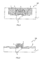
- FIGS. 1 and 2 are sectional views illustrating examples of LED device 100.
- the LED device illustrated in FIG. 1 includes an LED element having LED chip 3, wavelength conversion part 6 formed on the LED device, and transparent resin layer 7.
- LED device 100 illustrated in FIG. 1 has package (LED substrate) 1, metal part 2, LED chip 3, and interconnection 4 that connects metal part 2 and LED chip 3.
- package 1 can be made, for example, of a liquid crystal polymer or a ceramic, the material thereof is not particularly limited as long as it has an insulating property and heat resistance. Also, the shape thereof is not particularly limited; for example, it may have a recess as illustrated in FIG. 1 , or it may also have a flat shape as illustrated in FIG. 2 .
- LED chip 3 may emanate, for example, blue light (a light of about 420 to 485 nm), and may emanate ultraviolet light.
- LED chip 3 is not particularly limited.
- LED chip 3 can be a laminate of an n-GaN compound semiconductor layer (cladding layer), an InGaN compound semiconductor layer (light emitting layer), a p-GaN compound semiconductor layer (cladding layer), and a transparent electrode layer.
- LED chip 3 can have an emission surface of 200 to 300 ⁇ m ⁇ 200 to 300 ⁇ m, for example.
- LED chip 3 typically has a height of about 50 to 200 ⁇ m.
- Metal part 2 can be an interconnection made of metal such as silver.
- Metal part 2 may function as a reflection plate that reflects light, or the like emitted by LED chip 3.
- Metal part 2 and LED chip 3 may be connected to each other through interconnection 4 as illustrated in FIG. 1 , or may be connected to each other through bump electrode 5 as illustrated in FIG. 2 .
- the mode in which metal part 2 and LED chip 3 are connected through interconnection 4 is called wire-bonding, and the mode in which they are connected through bump electrode 5 is called flip-chip bonding.
- LED device 100 as illustrated in FIGS. 1 and 2 only has one LED chip 3 being disposed in package 1; however a plurality of LED chips 3 may also be disposed in package 1.
- Wavelength conversion part 6 is a layer to which the phosphor particles are bound with a translucent ceramic. Wavelength conversion part 6, upon receipt of a specific wavelength light (excitation light) emitted by LED chip 3, emanates another specific wavelength light (fluorescence). Mixing of excitation light with fluorescence allows the light from LED device 100 to be a desired light. For example, when the light emitted by LED chip 3 is blue and the fluorescence emanated by phosphor particles contained in wavelength conversion part 6 is yellow or orange, the light from LED device 100 becomes white.
- wavelength conversion part 6 covers the emission surface of LED chip 3, and it is not necessary that it thoroughly covers package 1, metal part 2, interconnection 4, or the like. While the thickness of wavelength conversion part 6 is not particularly limited, the thickness is preferably typically 15 to 300 ⁇ m, and more preferably 30 to 200 ⁇ m. When the thickness of wavelength conversion part 6 is too large, there is a risk that a crack may occur in wavelength conversion part 6. On the other hand, when the thickness of wavelength conversion part 6 is too small, there is a possibility that sufficient phosphor particles may not be contained in wavelength conversion part 6, resulting in sufficient fluorescence not being obtained.
- the thickness of wavelength conversion part 6 means the maximum thickness of wavelength conversion part 6 formed on the emission surface of LED chip 3. The thickness of wavelength conversion part 6 is measured with a laser holographic gauge.
- Transparent resin layer 7 is formed so as to cover wavelength conversion part 6.
- Transparent resin layer 7 protects the LED element or wavelength conversion part 6 from the outer impact, gas, or the like. Further, if wavelength conversion part 6 is included, then a light coupling-out efficiency is also easily increased.
- the transparent resin layer is a layer that contains a transparent resin and has higher transparency to visible light.
- the transparent resin examples include silicone resins such as epoxy-modified silicone resin, alkyd-modified silicone resin, acryl-modified silicone resin, polyester-modified silicone resin, and phenyl silicone resins; epoxy resins; acryl resins; methacryl resins; urethane resins; and the like.
- silicone resins such as epoxy-modified silicone resin, alkyd-modified silicone resin, acryl-modified silicone resin, polyester-modified silicone resin, and phenyl silicone resins
- epoxy resins acryl resins; methacryl resins; urethane resins; and the like.
- phenyl silicone resins are preferable.
- the transparent resin is phenyl silicone resin, the wet resistance of the LED device is increased.
- the thickness of transparent resin layer 7 is not particularly limited, it is preferably typically 25 ⁇ m to 5 mm, and more preferably 1 to 3 mm. Generally, it is difficult to set the thickness of transparent resin layer 7 to 25 ⁇ m. On the other hand, from the viewpoint of downsizing the LED device, the thickness of transparent resin layer 7 is preferably 5 mm or less.
- the manufacturing method of the aforementioned LED device includes the following six steps:
- the aforementioned phosphor dispersion liquid is applied onto an LED element to form a phosphor layer.
- a translucent ceramic material composition is applied onto the phosphor layer, and then the translucent ceramic material is cured, thereby binding the phosphor layer with the translucent ceramic material.
- the phosphor particles in the phosphor dispersion liquid are uniformly dispersed.
- the concentration of phosphors in the phosphor dispersion liquid to be applied to the LED element becomes constant at the initial and terminal stages of the applying operation.
- the phosphor particles are not deteriorated. Accordingly, an LED device that emits irradiation light with desired chromaticity can be obtained.
- components other than phosphor particles are mixed to prepare a first dispersion liquid, and phosphor particles are mixed into the first dispersion liquid to prepare a phosphor dispersion liquid.
- the aforementioned LED element is provided.
- it can include steps of: electrically connecting a metal part formed in a package and an LED chip with each other; fixing the LED chip to the package; and the like.
- the aforementioned phosphor dispersion liquid is applied so as to cover a metal part (metal interconnection) of the aforementioned LED element and the emission surface of the LED chip to form a phosphor particle layer on the LED element.
- the phosphor dispersion liquid is applied so as to cover the emission surface of the LED chip.
- the means for application is not particularly limited. Examples of the methods of applying the phosphor dispersion liquid include conventionally known methods such as bar-coating method, spin coating method, spray coating method, dispensing method, and jet-dispensing method. When the phosphor dispersion liquid is applied with a spray applicator, or the like described later, the thickness of the phosphor particle layer can be smaller.
- the amount of application of the phosphor-containing composition is appropriately adjusted depending on the thickness of the phosphor particle layer.
- the thickness of the phosphor particle layer is preferably 15 to 300 ⁇ m, and more preferably 30 to 200 ⁇ m. When the thickness of the phosphor particle layer is less than 15 ⁇ m, there is a risk that the amount of the phosphor particles may become smaller, resulting in sufficient fluorescence not being obtained. On the other hand, when the thickness of the phosphor particle layer exceeds 300 ⁇ m, the concentration of the phosphor particles in the phosphor particle layer becomes excessively low, and thus there is a risk that the concentration of the phosphor particles may not be uniform.
- the thickness of the phosphor particle layer means the maximum thickness of the phosphor particle layer formed on the emission surface of the LED chip. The thickness of the phosphor particle layer is measured with a laser holographic gauge.
- the solvent in the phosphor dispersion liquid is preferably dried after application of the phosphor dispersion liquid.
- the temperature at the time of drying the solvent in the phosphor dispersion liquid is typically 20 to 200°C, and preferably 25 to 150°C. When the temperature is lower than 20°C, there is a possibility that the solvent may not be sufficiently volatilized. On the other hand, when the temperature exceeds 200°C, there is a possibility that it may adversely affect the LED chip.
- the time for drying is typically 0.1 to 30 minutes, and preferably 0.1 to 15 minutes, from the viewpoint of manufacturing efficiency.
- the spray applicator preferably includes a coating liquid tank that retains a phosphor dispersion liquid, a head having a nozzle for discharging a coating liquid, and a connector tube that allows fluid communication between the coating liquid tank and the nozzle.
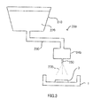
- FIG. 3 illustrates the outline of the spray applicator for applying the coating liquid.
- the phosphor dispersion liquid is loaded into coating liquid tank 210 in applicator 200 illustrated in FIG. 3 .
- Phosphor dispersion liquid 220 inside coating liquid tank 210 in applicator 200 illustrated in FIG. 3 is pressurized and supplied to head 240 through connector tube 230.
- Phosphor dispersion liquid 220 supplied to head 240 is discharged from nozzle 250, and is applied to the coating target (LED chip 3).
- discharging of coating liquid 270 from nozzle 250 is carried out by means of wind pressure.
- Nozzle 250 may be configured to have an openable and closable port at the tip thereof, so that ON/OFF of the discharging operation is controlled by opening or closing the port.
- the translucent ceramic material composition is applied so as to cover the aforementioned phosphor particle layer.
- the translucent ceramic material composition enters a gap in the phosphor particle layer to fill the gap of phosphor particles, laminar clay mineral particles, oxide microparticles, and the like contained in the phosphor particle layer.
- the translucent ceramic material composition contains a translucent ceramic material and a solvent, and contains inorganic particles, or the like, where necessary.
- the translucent ceramic material may be a compound that becomes a translucent ceramic (preferably a glass ceramic) by a sol-gel reaction.
- the translucent ceramic material include metal alkoxides, metal acetylacetonates, metal carboxylates, polysilazane oligomers, and the like, with metal alkoxides being preferable from the viewpoint of good reactivity.
- the metal alkoxides can be various metal alkoxides, but are preferably alkoxysilane or aryloxysilane from the viewpoint of the stability and manufacturing easiness of the translucent ceramic to be obtained.
- the alkoxysilane or aryloxysilane may be a monomolecular compound (monomer) such as tetraethoxysilane, but is preferably polysiloxane (oligomer).
- the polysiloxane is a compound obtained through linear or cyclic siloxane bonding of silane compounds. The preparation method of polysiloxane will be described later.
- the mass mean molecular weight of polysiloxane is preferably 1,000 to 3,000, more preferably 1,200 to 2,700, and still more preferably 1,500 to 2,000.
- the mass mean molecular weight of polysiloxane is less than 1,000, there is a risk that the viscosity of the translucent ceramic material composition may be too low.
- the mass mean molecular weight exceeds 3,000, the viscosity of the translucent ceramic material composition becomes higher, and there is a case where it may be difficult to apply the translucent ceramic material composition.
- the mass mean molecular weight is a value measured by gel permeation chromatography (in terms of polystyrene).
- the amount of polysiloxane contained in the translucent ceramic material composition is preferably 1 to 40 mass% based on the total mass of the translucent ceramic material composition, and more preferably 2 to 30 mass%.
- the amount of polysiloxane is less than 1 mass%, there is a risk that a cured product of polysiloxane may not bind phosphor particles, and the like sufficiently.
- the amount of polysiloxane exceeds 40 mass%, the viscosity of the translucent ceramic material composition becomes excessively high, and there is a case where it may be difficult to apply the translucent ceramic material composition.
- the translucent ceramic material composition contains a solvent. It is sufficient that the solvent can dissolve or uniformly disperse the aforementioned translucent ceramic material.
- the solvent include: monovalent aliphatic alcohols such as methanol, ethanol, propanol, and n-butanol; alkyl carboxylic acid esters such as methyl-3-methoxy propionate, and ethyl-3-ethoxy propionate; polyvalent aliphatic alcohols such as ethylene glycol, diethylene glycol, propylene glycol, glycerin, trimethylol propane, and hexane triol; polyvalent aliphatic alcohol monoethers such as ethylene glycol monomethyl ether, ethylene glycol monoethyl ether, ethylene glycol monopropyl ether, ethylene glycol monobutyl ether, diethylene glycol monomethyl ether, diethylene glycol monoethyl ether, diethylene glycol monopropyl ether, diethylene glycol monobutyl ether, propylene
- the solvents include water.
- the amount of water is preferably 3 to 15 mass% based on the total mass of the translucent ceramic material composition, and more preferably 5 to 10 mass%.
- the water content is preferably 10 to 120 mass parts based on 100 mass parts of polysiloxane, and more preferably 80 to 100 mass parts.
- the amount of water contained in the translucent ceramic material composition is too small, there is a case where polysiloxane may not be sufficiently hydrolyzed after application of the translucent ceramic material.
- the amount of water contained in the translucent ceramic material composition is excessive, there is a risk that hydrolysis, or the like may occur during storing of the translucent ceramic material composition, causing the translucent ceramic material composition to be gelated.
- the solvents include organic solvents (e.g., ethylene glycol, propylene glycol) having a boiling point of 150°C or higher.
- organic solvents e.g., ethylene glycol, propylene glycol
- the storage stability of the translucent ceramic material composition is increased. Further, the solvent is hard to be volatilized in the applicator, and thus the translucent ceramic material composition can be stably applied from the applicator.
- the boiling point of the solvent contained in the translucent ceramic material composition is preferably 250°C or lower.
- the boiling point of the solvent exceeds 250°C, there is a risk that it may take time to dry the translucent ceramic material composition, or that the solvent may not be dried sufficiently.
- the translucent ceramic material composition may contain inorganic particles.
- inorganic particles When inorganic particles are contained in the translucent ceramic material composition, at the time when the translucent ceramic material composition is cured, a stress occurring on the film is alleviated, making it difficult for a crack to occur in the wavelength conversion part.
- the refractive index of the inorganic particles is higher than the refractive index of the translucent ceramic materials (e.g., polysiloxane, polysilazane).
- the refractive index of the resulting wavelength conversion part is increased.
- the refractive index of the LED element LED chip
- the difference in the refractive index between the LED element and the wavelength conversion part becomes smaller, leading to less reflection of light at the interface between the LED element and the wavelength conversion part. That is, the light coupling-out efficiency of the LED device is increased.
- the inorganic particles are preferably porous particles, and the specific surface area thereof is preferably 200 m 2 /g or higher.
- a solvent enters pores, allowing the viscosity of the translucent ceramic material composition to be increased.
- the viscosity of the translucent ceramic material composition is not determined depending solely on the amount of inorganic particles, but also varies depending on the ratio between inorganic particles and a solvent, the amount of other components, or the like.
- the mean primary particle diameter of the inorganic particles is preferably 5 to 100 nm, more preferably 5 to 80 nm, and still more preferably 5 to 50 nm.
- the mean primary particle diameter of the inorganic particles is measured by Coulter counter method.
- inorganic particles examples include zirconium oxide, titanium oxide, tin oxide, cerium oxide, niobium oxide, zinc oxide, and the like. Among these, the inorganic particles are preferably zirconium oxide microparticles. Only one type of inorganic particle or two or more types of inorganic particles may be contained in the translucent ceramic material composition.
- the inorganic particles may be those the surface of which is treated with a silane coupling agent or a titanium coupling agent.
- the surface-treated inorganic particles are easily dispersed uniformly in the translucent ceramic material composition.
- the amount of the inorganic particles in the translucent ceramic material composition is preferably 10 to 60 mass% based on the total amount of the solid content of the translucent ceramic material composition, more preferably 15 to 45 mass%, and still more preferably 20 to 30 mass%.
- the amount of the inorganic particles is too small, the aforementioned crack suppression effect is not increased, and the refractive index-improving effect does not become sufficient, either.
- the amount of the inorganic particles is too large, the amount of the translucent ceramic material (binder) is decreased relatively, so that there is a risk that the binding of the phosphor particles with a transparent ceramic may be insufficient, or that the strength of the wavelength conversion part may be lowered.
- the method of applying the translucent ceramic material composition is not particularly limited.
- Example thereof can be blade application, spin coating application, dispenser application, and spray application; according to the spray application, it is possible to form a wavelength conversion part with smaller thickness.
- the spray applicator can be similar to a spray applicator to be used for the application of the aforementioned phosphor dispersion liquid.
- the amount of application of the translucent ceramic material composition is set to be an amount that is capable of sufficiently binding phosphor particles, laminar clay mineral particles, oxide microparticles, and the like contained in the phosphor particle layer.
- the amount of application of the translucent ceramic material composition is too small, the phosphor particles may not be sufficiently bound, and thus there is a risk that the strength of the wavelength conversion part may be lowered.
- Polysiloxane which is a translucent ceramic material to be added to the translucent ceramic material composition can be obtained by polymerizing an alkoxysilane compound or an aryloxysilane compound.
- the alkoxysilane compound or aryloxysilane compound is represented, for example, by the following general formula (II): Si (OR) n Y 4-n (II).
- n represents the number of an alkoxy group or an aryloxy group (OR), and is an integer of 2 or more and 4 or less.
- R represents, each independently, an alkyl group or a phenyl group, and preferably represents an alkyl group having 1 to 5 carbon atoms, or a phenyl group.
- Y represents a hydrogen atom, or a monovalent organic group.
- the monovalent organic group represented by Y include an aliphatic group, an alicyclic group, an aromatic group, and an alicyclic aromatic group having 1 to 1,000, preferably 500 or less, more preferably 100 or less, still more preferably 50 or less, and particularly preferably 6 or less carbon atoms.
- the monovalent organic group may be a group in which an aliphatic group, an alicyclic group, an aromatic group, and an alicyclic aromatic group are linked via a linking group.
- the linking group may be an atom such as O, N or S, or an atomic group containing these atoms.
- the monovalent organic group represented by Y may have a substituent.
- substituents include: halogen atoms such as F, Cl, Br and I; and organic functional groups such as a vinyl group, a methacryloxy group, an acryloxy group, a styryl group, a mercapto group, an epoxy group, an epoxycyclohexyl group, a glycidoxy group, an amino group, a cyano group, a nitro group, a sulfonate group, a carboxy group, a hydroxy group, an acyl group, an alkoxy group, an imino group, and a phenyl group.
- a group represented by Y is particularly a methyl group.
- Y is a methyl group, the light resistance and the heat resistance of the wavelength conversion part become better.
- the alkoxysilane or aryloxysilane represented by the aforementioned general formula (II) includes the following tetrafunctional silane compounds, trifunctional silane compounds, and bifunctional silane compounds.
- tetrafunctional silane compounds include: tetraalkoxysilanes, tetraaryloxysilanes, or the like such as tetramethoxysilane, tetraethoxysilane, tetrapropoxysilane, tetrabutoxysilane, tetrapentyloxysilane, tetraphenyoxysilane, trimethoxymonoethoxysilane, dimethoxydiethoxysilane, triethoxymonomethoxysilane, trimethoxymonopropoxysilane, monomethoxytributoxysilane, monomethoxytripentyloxysilane, monomethoxytriphenyloxysilane, dimethoxydipropoxysilane, tripropoxymonomethoxysilane, trimethoxymonobutoxysilane, dimethoxydibutoxysilane, triethoxymonopropoxysilane, diethoxyd
- trifunctional silane compounds include: monohydrosilane compounds such as trimethoxysilane, triethoxysilane, tripropoxysilane, tripentyloxysilane, triphenyloxysilane, dimethoxymonoethoxysilane, diethoxymonomethoxysilane, dipropoxymonomethoxysilane, dipropoxymonoethoxysilane, dipentyloxylmonomethoxysilane, dipentyloxymonoethoxysilane, dipentyloxymonopropoxysilane, diphenyloxylmonomethoxysilane, diphenyloxymonoethoxysilane, diphenyloxymonopropoxysilane, methoxyethoxypropoxysilane, monopropoxydimethoxysilane, monopropoxydiethoxysilane, monobutoxydimethoxysilane, monopentyloxydiethoxysilane, and monophenyloxydiethoxysi
- bifunctional silane compounds include: dimethoxysilane, diethoxysilane, dipropoxysilane, dipentyloxysilane, diphenyloxysilane, methoxyethoxysilane, methoxypropoxysilane, methoxypentyloxysilane, methoxyphenyloxysilane, ethoxypropoxysilane, ethoxypentyloxysilane, ethoxyphenyloxysilane, methyldimethoxysilane, methylmethoxyethoxysilane, methyldiethoxysilane, methylmethoxypropoxysilane, methylmethoxypentyloxysilane, methylmethoxyphenyloxysilane, ethyldipropoxysilane, ethylmethoxypropoxysilane, ethyldipentyloxysilane, ethyldiphenyloxysilane, propyl
- Polysiloxane is prepared by a method of hydrolyzing the aforementioned silane compound in the presence of an acid catalyst, water, and an organic solvent, followed by a condensation reaction.
- the mass mean molecular weight of polysiloxane can be adjusted depending on reaction conditions (in particular, reaction time), or the like.
- a tetrafunctional silane compound and a trifunctional compound or a bifunctional compound may be mixed in advance at a desired molar ratio to polymerize them randomly. Further, it may also be possible to polymerize a trifunctional silane compound or a bifunctional silane compound alone to some degree to obtain an oligomer, and then polymerize only a tetrafunctional silane compound with the oligomer to obtain a block copolymer.
- the acid catalyst for the preparation of polysiloxane is an organic sulfonic acid represented by the following general formula (III): R 8 -SO 3 H (III).
- a hydrocarbon group represented by R 8 is a linear, branched or cyclic, saturated or unsaturated hydrocarbon group having 1 to 20 carbon atoms.
- a cyclic hydrocarbon group include an aromatic hydrocarbon group such as a phenyl group, a naphthyl group, or an anthryl group, with a phenyl group being preferable.
- the hydrocarbon group represented by R 8 in the general formula (III) may have a substituent.
- substituents include: a linear, branched or cyclic, saturated or unsaturated hydrocarbon group having 1 to 20 carbon atoms; halogen atoms such as a fluorine atom; a sulfonate group; a carboxyl group; a hydroxyl group; an amino group; a cyano group; and the like.
- the organic sulfonic acid represented by the aforementioned general formula (III) is particularly preferably nonafluorobutane sulfonic acid, methanesulfonic acid, trifluoromethane sulfonic acid, or dodecylbenzenesulfonic acid.
- the amount of the acid catalyst to be added at the time of preparing polysiloxane is preferably 1 to 1,000 mass ppm based on the total amount of a polysiloxane preparation liquid, and more preferably 5 to 800 mass ppm.
- the water addition ratio is a ratio (%) of the molar number of a water molecule to be added, based on the molar number of an alkoxy group or an aryloxy group of a silane compound contained in a polysiloxane preparation liquid.
- the water addition ratio is preferably 50 to 200%, and more preferably 75 to 180%.
- Examples of a solvent to be added at the time of preparing polysiloxane include: monovalent aliphatic alcohols such as methanol, ethanol, propanol, and n-butanol; alkylcarboxylic acid esters such as methyl-3-methoxy propionate, and ethyl-3-ethoxy propionate; polyvalent aliphatic alcohols such as ethylene glycol, diethylene glycol, propylene glycol, glycerin, trimethylolpropane, and hexanetriol; polyvalent aliphatic alcohol monoethers such as ethyleneglycol monomethylether, ethyleneglycol monoethylether, ethyleneglycol monopropylether, ethyleneglycol monobutylether, diethyleneglycol monomethylether, diethyleneglycol monoethylether, diethyleneglycol monopropylether, diethyleneglycol monobutylether, propyleneglycol monomethylether, propyleneglycol mono
- the translucent ceramic material composition After application of the translucent ceramic material composition, the translucent ceramic material composition is dried and cured. By curing the translucent ceramic material composition, it becomes possible to obtain a wavelength conversion part in which a phosphor particle layer is bound with the translucent ceramic material.
- the method of drying/curing the translucent ceramic material is appropriately selected depending on the types of the translucent ceramic material.
- the translucent ceramic material is polysiloxane
- a coating film is heated preferably to 100°C or higher, and is heated more preferably to 150 to 300°C.
- the heating temperature is lower than 100°C, the moisture occurring at the time of dehydration condensation cannot be sufficiently removed, and thus there is a risk that the light resistance of the wavelength conversion part may be lowered.
- a composition for a transparent resin layer containing a transparent resin may be applied onto the aforementioned wavelength conversion part to form a transparent resin layer.
- the transparent resin contained in the composition for the transparent resin layer is not particularly limited as long as it is a curable resin, or the like which is transparent to visible light, and the aforementioned various transparent resins can be adopted.
- the composition for the transparent resin layer may contain a solvent where necessary. The types of the solvent are appropriately selected depending on the types of the transparent resin or the viscosity of the composition for the transparent resin layer.
- the method of application of the composition for the transparent resin layer is not particularly limited, and, for example, an application method using a general applicator such as a dispenser can be adopted. Further, the curing method and the curing condition of the composition for the transparent resin layer are appropriately selected depending on the types of the transparent resin.
- One example of the curing method includes thermal curing.
- the phosphor particles to be used for Examples and Comparative Examples were prepared as follows:
- the resulting calcined product was pulverized, washed, separated and dried to obtain yellow phosphor particles having a volume mean particle diameter of about 1 ⁇ m.
- An excitation light having a wavelength of 465 nm was irradiated to the obtained yellow phosphor particles to measure a wavelength of the light emanated by the yellow phosphor particles.
- the yellow phosphor particles had a peak wavelength at a wavelength of roughly 570 nm.
- LED element For an LED element, there is provided an LED chip-mounted package (LED element) with one blue LED chip (cuboid shape; 200 ⁇ 300 ⁇ 100 ⁇ m) being flip-chip mounted at the center of a housing part of a round package (opening diameter: 3 mm, bottom diameter: 2 mm, wall angle: 60°).
- BEN-GEL available from Hojun Corporation: natural bentonite
- SILYSIA 470 available from Fuji Silysia Chemical Ltd.
- oxide microparticles were added into a mixed solvent of 70 g of propylene glycol, 30 g of 1,3-butanediol and 50 g of isopropyl alcohol.
- the liquid mixture was mixed so as to have a viscosity of 45 mPa ⁇ s using TK Auto Homomixer (available from PRIMIX Corporation) to obtain a first dispersion liquid.
- the viscosity of the first dispersion liquid was adjusted with the dispersing time of the liquid mixture and with a shearing force at the time of dispersion.
- phosphor particles were added to the first dispersion liquid.
- the mixture was stirred and mixed using Awatori Rentaro (available from THINKY) to obtain a phosphor dispersion liquid.
- the viscosity of the obtained phosphor dispersion liquid was 100 mPa ⁇ s.
- a liquid mixture of laminar clay mineral particles, oxide microparticles and a solvent having the same composition as that for Sample 1 was mixed so as to have a viscosity of 55 mPa ⁇ s using TK Auto Homomixer (available from PRIMIX Corporation) to obtain a first dispersion liquid.
- a liquid mixture of laminar clay mineral particles, oxide microparticles and a solvent having the same composition as that for Sample 1 was mixed so as to have a viscosity of 200 mPa ⁇ s using TK Auto Homomixer (available from PRIMIX Corporation) to obtain a first dispersion liquid.
- a liquid mixture of laminar clay mineral particles, oxide microparticles and a solvent having the same composition as that for Sample 1 was mixed so as to have a viscosity of 450 mPa ⁇ s using TK Auto Homomixer (available from PRIMIX Corporation) to obtain a first dispersion liquid.
- a liquid mixture of laminar clay mineral particles, oxide microparticles and a solvent having the same composition as that for Sample 1 was mixed so as to have a viscosity of 550 mPa ⁇ s using TK Auto Homomixer (available from PRIMIX Corporation) to obtain a first dispersion liquid.
- a liquid mixture of laminar clay mineral particles, oxide microparticles and a solvent having the same composition as that for Sample 1 was mixed so as to have a viscosity of 200 mPa ⁇ s using TK Auto Homomixer (available from PRIMIX Corporation) to obtain a first dispersion liquid.
- phosphor particles were added to the first dispersion liquid.
- the mixture was stirred and mixed using TK Auto Homomixer (available from PRIMIX Corporation) to obtain a phosphor dispersion liquid.
- the viscosity of the obtained phosphor dispersion liquid was 230 mPa ⁇ s.
- a liquid mixture of laminar clay mineral particles, oxide microparticles and a solvent having the same composition as that for Sample 1 was mixed so as to have a viscosity of 200 mPa ⁇ s using TK Auto Homomixer (available from PRIMIX Corporation) to obtain a first dispersion liquid.
- a liquid mixture of laminar clay mineral particles, oxide microparticles and a solvent having the same composition as that for Sample 1 was mixed so as to have a viscosity of 200 mPa ⁇ s using TK Auto Homomixer (available from PRIMIX Corporation) to obtain a first dispersion liquid.
- a liquid mixture of laminar clay mineral particles, oxide microparticles and a solvent having the same composition as that for Sample 1 was mixed so as to have a viscosity of 200 mPa ⁇ s using TK Auto Homomixer (available from PRIMIX Corporation) to obtain a first dispersion liquid.
- a liquid mixture of laminar clay mineral particles, oxide microparticles and a solvent having the same composition as that for Sample 1 was mixed so as to have a viscosity of 200 mPa ⁇ s using TK Auto Homomixer (available from PRIMIX Corporation) to obtain a first dispersion liquid.
- Micromica MK-100 available from CO-OP CHEMICAL Co., Ltd.: synthetic mica
- AEROSIL RX300 available from Nippon Aerosil Co., Ltd.
- the liquid mixture was mixed so as to have a viscosity of 250 mPa ⁇ s using Apex Mill (Kotobuki Industries Co., Ltd.) to obtain a first dispersion liquid.
- Kunipia F available from KUNIMINE Industry Co., Ltd.: montmorillonite
- Nipsil SS-50F available from Tosoh Silica Corporation
- the liquid mixture was mixed so as to have a viscosity of 200 mPa ⁇ s using Cleamix (M Technique Co., Ltd.) to obtain a first dispersion liquid.
- Lucentite SWN available from CO-OP CHEMICAL CO., LTD.: smectite
- Microbead SP-1 available from JGC Catalysts and Chemicals Ltd.
- the liquid mixture was mixed so as to have a viscosity of 180 mPa ⁇ s using Nanomizer (Yoshida Kikai Co., Ltd.) to obtain a first dispersion liquid.
- Lucentite SWN available from CO-OP CHEMICAL CO., LTD.: smectite
- Sylysia 470 Feji Silysia Chemical Ltd.
- oxide microparticles were added into a mixed solvent of 40 g of propylene glycol, 40 g of 1,3-butanediol and 80 g of isopropyl alcohol.
- the liquid mixture was mixed so as to have a viscosity of 150 mPa ⁇ s using ULTRA-TURRAX (IKA Co., Ltd.) to obtain a first dispersion liquid.
- BEN-GEL available from Hojun Corporation: natural bentonite
- Sylysia 470 Feji Silysia Chemical Ltd.
- 90 g of phosphor particles were added to a mixed solvent of 70 g of propylene glycol, 30 g of 1,3-butanediol and 50 g of isopropyl alcohol.
- the liquid mixture was dispersed using TK Auto Homomixer (available from PRIMIX Corporation) to obtain a phosphor dispersion liquid.
- the viscosity of the obtained phosphor dispersion liquid was 250 mPa ⁇ s.
- BEN-GEL available from Hojun Corporation: natural bentonite
- Sylysia 470 Feji Silysia Chemical Ltd.
- 90 g of phosphor particles were added to a mixed solvent of 70 g of propylene glycol, 30 g of 1,3-butanediol and 50 g of isopropyl alcohol.
- the mixture was dispersed using Awatori Rentaro (available from THINKY) to obtain a phosphor dispersion liquid.
- the viscosity of the obtained phosphor dispersion liquid was 60 mPa ⁇ s.
- a liquid mixture of laminar clay mineral particles, oxide microparticles and a solvent having the same composition as that for Sample 1 was dispersed using Awatori Rentaro (available from THINKY) to obtain a first dispersion liquid.
- the viscosity of the obtained first dispersion liquid was 30 mPa ⁇ s.
- phosphor particles were added to the first dispersion liquid.
- the mixture was stirred and mixed using TK Auto Homomixer (available from PRIMIX Corporation) to obtain a phosphor dispersion liquid.
- the viscosity of the obtained phosphor dispersion liquid was 180 mPa ⁇ s.
- a liquid mixture of laminar clay mineral particles, oxide microparticles and a solvent having the same composition as that for Sample 1 was dispersed using Awatori Rentaro (available from THINKY) to obtain a first dispersion liquid.
- the viscosity of the obtained first dispersion liquid was 30 mPa ⁇ s.
- the phosphor dispersion liquids prepared in Samples 1 to 19 were applied to the inside of the recess of the aforementioned LED element using a spray applicator.
- the conditions for the spray application were set such that the spraying pressure was 0.2 MPa and the relative movement speed between the spray nozzle and the emitting light element from the LED element was 100 mm/s.
- heating was carried out at 150°C for 1 hour to form a phosphor layer.
- a translucent ceramic material composition was spray-applied onto the phosphor layer.
- the translucent ceramic material composition there was adopted a liquid mixture of 15 mass parts of tetramethoxysilane KBM04 (available from Shin-Etsu Chemical Co., Ltd.), 5 mass parts of methyltrimethoxysilane KBM13 (available from Shin-Etsu Chemical Co., Ltd.), 40 mass parts of isopropyl alcohol, 40 mass parts of ethanol, and 2 mass parts of hydrochloric acid.
- the conditions for the spray application were set such that the spraying pressure was 0.1 MPa and the relative movement speed between the spray nozzle and the emitting light element from the LED element was 100 mm/s. After the application of the translucent ceramic material composition, heating was carried out at 150°C for 1 hour to obtain a wavelength conversion part with a phosphor layer being bound thereto with a translucent ceramic.
- phenyl silicone available from Shin-Etsu Chemical Co., Ltd.; KER-6000
- KER-6000 phenyl silicone
- LED devices were produced according to the method similar to those mentioned above using the respective phosphor dispersion liquids.
- spectroradiometer CS-200 available from Konica Minolta Sensing, Inc. was used for measurement.
- LED devices (the same as those produced at Measurement of Chromaticity) were produced using the phosphor dispersion liquids prepared in the aforementioned Samples 1 to 19 to measure the total luminous flux values thereof.
- the ratio of the total luminous flux value in each of Examples and Comparative Examples to the total luminous flux value of the sample in each of the corresponding to Examples and Comparative Examples was determined. This ratio was evaluated as follows. The results are given in Tables 1 and 2.
- the phosphor dispersion liquid produced by the present invention phosphor particles are not deteriorated. Further, the phosphor particles are hard to settle, allowing uniform dispersion state to be maintained. Therefore, an LED device manufactured using this phosphor dispersion liquid has a higher light coupling-out efficiency, and further has a uniform chromaticity of irradiation light. Therefore, it is applicable not only to indoor or outdoor lighting apparatuses, but also to applications requiring larger amount of light and chromaticity uniformity, such as an automobile headlight.
Landscapes
- Chemical & Material Sciences (AREA)
- Engineering & Computer Science (AREA)
- Materials Engineering (AREA)
- Organic Chemistry (AREA)
- Inorganic Chemistry (AREA)
- Led Device Packages (AREA)
- Luminescent Compositions (AREA)
Applications Claiming Priority (2)
| Application Number | Priority Date | Filing Date | Title |
|---|---|---|---|
| JP2012179295 | 2012-08-13 | ||
| PCT/JP2013/004830 WO2014027460A1 (fr) | 2012-08-13 | 2013-08-12 | Procédé de fabrication de liquide de dispersion de luminophore et procédé de fabrication de dispositif de diode électroluminescente |
Publications (2)
| Publication Number | Publication Date |
|---|---|
| EP2853577A1 true EP2853577A1 (fr) | 2015-04-01 |
| EP2853577A4 EP2853577A4 (fr) | 2016-01-06 |
Family
ID=50685506
Family Applications (1)
| Application Number | Title | Priority Date | Filing Date |
|---|---|---|---|
| EP13879580.2A Withdrawn EP2853577A4 (fr) | 2012-08-13 | 2013-08-12 | Procédé de fabrication de liquide de dispersion de luminophore et procédé de fabrication de dispositif de diode électroluminescente |
Country Status (6)
| Country | Link |
|---|---|
| US (1) | US9175215B2 (fr) |
| EP (1) | EP2853577A4 (fr) |
| JP (1) | JP5541433B1 (fr) |
| KR (1) | KR101538603B1 (fr) |
| CN (1) | CN104334680B (fr) |
| WO (1) | WO2014027460A1 (fr) |
Families Citing this family (11)
| Publication number | Priority date | Publication date | Assignee | Title |
|---|---|---|---|---|
| EP3097588B1 (fr) * | 2014-01-21 | 2021-02-24 | Lumileds LLC | Module del hybride à montage direct sur carte à encapsulation à motifs et procédé de sa production |
| WO2016017592A1 (fr) * | 2014-07-28 | 2016-02-04 | 住友化学株式会社 | Composition de matériau d'étanchéité à base de silicone et dispositif électroluminescent semi-conducteur |
| WO2016206348A1 (fr) * | 2015-06-24 | 2016-12-29 | 林立宸 | Procédé de fabrication d'un ensemble luminescent à puce |
| KR20170089053A (ko) * | 2016-01-25 | 2017-08-03 | 삼성전자주식회사 | 수지 도포 장치 및 이를 사용한 발광소자 패키지 제조방법 |
| JP6447557B2 (ja) * | 2016-03-24 | 2019-01-09 | 日亜化学工業株式会社 | 発光装置の製造方法 |
| CN109073801A (zh) * | 2016-04-25 | 2018-12-21 | 日本特殊陶业株式会社 | 波长转换构件、其制造方法及发光装置 |
| JP6790563B2 (ja) * | 2016-08-05 | 2020-11-25 | 日本電気硝子株式会社 | 波長変換部材の製造方法 |
| KR101898433B1 (ko) * | 2017-02-07 | 2018-09-14 | 도레이첨단소재 주식회사 | 파장 변환 필름 |
| KR102249134B1 (ko) * | 2019-09-11 | 2021-05-07 | 한국광기술원 | 옐로우 링 현상이 저감된 형광체 플레이트 및 그의 제조방법 |
| JPWO2022107794A1 (fr) * | 2020-11-19 | 2022-05-27 | ||
| TW202233802A (zh) * | 2021-02-17 | 2022-09-01 | 歆熾電氣技術股份有限公司 | 光轉換複合材料以及製造光轉換複合材料之方法 |
Family Cites Families (18)
| Publication number | Priority date | Publication date | Assignee | Title |
|---|---|---|---|---|
| JP3978961B2 (ja) * | 1998-12-25 | 2007-09-19 | 特種製紙株式会社 | 偽造防止用紙に使用する蛍光発色粒子、その製造方法、及び蛍光発色粒子を使用した偽造防止用紙 |
| JP3867830B2 (ja) * | 1999-12-06 | 2007-01-17 | 東芝テック株式会社 | 電気掃除機 |
| JP2001181614A (ja) | 1999-12-24 | 2001-07-03 | Teikoku Tsushin Kogyo Co Ltd | El素子用蛍光体ペースト及びその製造方法 |
| JP4101468B2 (ja) | 2001-04-09 | 2008-06-18 | 豊田合成株式会社 | 発光装置の製造方法 |
| JP4306224B2 (ja) | 2002-10-31 | 2009-07-29 | パナソニック電工株式会社 | 発光装置の製造方法 |
| KR101142725B1 (ko) * | 2003-03-13 | 2012-05-04 | 니치아 카가쿠 고교 가부시키가이샤 | 발광막, 발광장치, 발광막의 제조방법 및 발광장치의제조방법 |
| JP4591690B2 (ja) | 2005-06-06 | 2010-12-01 | 信越化学工業株式会社 | 蛍光物質入りled発光装置 |
| KR100746749B1 (ko) * | 2006-03-15 | 2007-08-09 | (주)케이디티 | 광 여기 시트 |
| JP5252621B2 (ja) * | 2007-12-28 | 2013-07-31 | 独立行政法人産業技術総合研究所 | 粘土を主成分とするフレキシブル蛍光フィルム |
| WO2011102272A1 (fr) * | 2010-02-19 | 2011-08-25 | 東レ株式会社 | Silicone durci contenant un luminophore, son procédé de fabrication, composition de silicone contenant un luminophore, précurseur de la composition, produits moulés en forme de feuille, boîtier pour del, dispositif électroluminescent et procédé de fabrication de substrat monté sur del |
| WO2011129320A1 (fr) * | 2010-04-13 | 2011-10-20 | コニカミノルタオプト株式会社 | Dispositif électroluminescent et procédé de fabrication de celui-ci |
| JP2011238778A (ja) * | 2010-05-11 | 2011-11-24 | Konica Minolta Opto Inc | 波長変換素子の製造方法、波長変換素子および発光装置 |
| CN103081142B (zh) | 2010-08-17 | 2015-01-14 | 柯尼卡美能达先进多层薄膜株式会社 | 发光装置的制造方法 |
| CN103597621A (zh) * | 2011-03-11 | 2014-02-19 | 柯尼卡美能达株式会社 | 发光装置的制造方法及荧光体混合液 |
| US8915619B2 (en) * | 2011-06-01 | 2014-12-23 | Koninklijke Philips N.V. | Light emitting module comprising a thermal conductor, a lamp and a luminaire |
| EP2752897A4 (fr) * | 2011-10-07 | 2015-04-29 | Konica Minolta Inc | Procédé de fabrication de dispositif à del et solution à matière fluorescente dispersée utilisée dans celui-ci |
| US9184352B2 (en) * | 2011-10-07 | 2015-11-10 | Konica Minolta, Inc. | Phosphor dispersion liquid, and production method for LED device using same |
| US20140009060A1 (en) * | 2012-06-29 | 2014-01-09 | Nitto Denko Corporation | Phosphor layer-covered led, producing method thereof, and led device |
-
2013
- 2013-08-12 EP EP13879580.2A patent/EP2853577A4/fr not_active Withdrawn
- 2013-08-12 JP JP2014508623A patent/JP5541433B1/ja not_active Expired - Fee Related
- 2013-08-12 WO PCT/JP2013/004830 patent/WO2014027460A1/fr not_active Ceased
- 2013-08-12 KR KR1020147033045A patent/KR101538603B1/ko not_active Expired - Fee Related
- 2013-08-12 CN CN201380028146.0A patent/CN104334680B/zh not_active Expired - Fee Related
- 2013-08-12 US US14/408,914 patent/US9175215B2/en not_active Expired - Fee Related
Also Published As
| Publication number | Publication date |
|---|---|
| JP5541433B1 (ja) | 2014-07-09 |
| CN104334680B (zh) | 2016-01-27 |
| WO2014027460A1 (fr) | 2014-02-20 |
| US9175215B2 (en) | 2015-11-03 |
| JPWO2014027460A1 (ja) | 2016-07-25 |
| CN104334680A (zh) | 2015-02-04 |
| EP2853577A4 (fr) | 2016-01-06 |
| KR101538603B1 (ko) | 2015-07-21 |
| US20150140700A1 (en) | 2015-05-21 |
| KR20140147147A (ko) | 2014-12-29 |
Similar Documents
| Publication | Publication Date | Title |
|---|---|---|
| US9175215B2 (en) | Method for producing phosphor dispersion liquid and method for manufacturing LED device | |
| US9184352B2 (en) | Phosphor dispersion liquid, and production method for LED device using same | |
| EP2940743A1 (fr) | Dispositif électroluminescent | |
| JPWO2014109293A1 (ja) | Led装置およびその製造に用いられる塗布液 | |
| WO2014103326A1 (fr) | Liquide de revêtement et dispositif à del pourvu d'une couche réfléchissante formée d'un produit durci dudit liquide de revêtement | |
| JP5910340B2 (ja) | Led装置、及びその製造方法 | |
| US20160002526A1 (en) | Phosphor dispersion, led device and method for manufacturing same | |
| JP2011238778A (ja) | 波長変換素子の製造方法、波長変換素子および発光装置 | |
| WO2013121903A1 (fr) | Élément de conversion de longueur d'onde et son procédé de fabrication et dispositif électroluminescent et son procédé de fabrication | |
| JP2014138081A (ja) | 発光装置、波長変換・光拡散素子及びそれらの製造方法、光拡散セラミック層形成用組成物 | |
| JP5803541B2 (ja) | Led装置およびその製造方法、並びにそれに用いる蛍光体分散液 | |
| JP2014127495A (ja) | Led装置、及びその製造方法 | |
| JP2014019844A (ja) | 蛍光体分散液及びled装置の製造方法 | |
| JP5874425B2 (ja) | 波長変換素子及びその製造方法、発光装置及びその製造方法 | |
| JP5880566B2 (ja) | Led装置 | |
| JP2016154179A (ja) | 発光装置、及びその製造方法 | |
| JP5747994B2 (ja) | 波長変換素子及びその製造方法、発光装置及びその製造方法 | |
| JP5729327B2 (ja) | Led装置の製造方法 | |
| JP2016181535A (ja) | 発光装置、および発光装置製造用の塗布液 | |
| JP2014160713A (ja) | Led装置の製造方法 | |
| WO2013187067A1 (fr) | Dispositif à del et son procédé de production | |
| WO2016047745A1 (fr) | Liquide de revêtement, procédé de production de dispositif à del l'utilisant, et dispositif à del | |
| JPWO2014087629A1 (ja) | ディスペンサー塗布用透光性セラミック材料、及びこれを用いたled装置の製造方法 | |
| JP2017011130A (ja) | 高比重粒子分散用溶液、及びこれを含む蛍光体分散液、並びに発光装置、及びその製造方法 | |
| JP2014165463A (ja) | 発光装置及びその製造方法 |
Legal Events
| Date | Code | Title | Description |
|---|---|---|---|
| PUAI | Public reference made under article 153(3) epc to a published international application that has entered the european phase |
Free format text: ORIGINAL CODE: 0009012 |
|
| 17P | Request for examination filed |
Effective date: 20141224 |
|
| AK | Designated contracting states |
Kind code of ref document: A1 Designated state(s): AL AT BE BG CH CY CZ DE DK EE ES FI FR GB GR HR HU IE IS IT LI LT LU LV MC MK MT NL NO PL PT RO RS SE SI SK SM TR |
|
| AX | Request for extension of the european patent |
Extension state: BA ME |
|
| DAX | Request for extension of the european patent (deleted) | ||
| RA4 | Supplementary search report drawn up and despatched (corrected) |
Effective date: 20151209 |
|
| RIC1 | Information provided on ipc code assigned before grant |
Ipc: H01L 33/50 20100101ALI20151203BHEP Ipc: C09K 11/08 20060101ALI20151203BHEP Ipc: C09K 11/02 20060101AFI20151203BHEP |
|
| STAA | Information on the status of an ep patent application or granted ep patent |
Free format text: STATUS: THE APPLICATION IS DEEMED TO BE WITHDRAWN |
|
| 18D | Application deemed to be withdrawn |
Effective date: 20160716 |