EP2855178B1 - Schwenkbare lageranordnung für einen stabilisator - Google Patents
Schwenkbare lageranordnung für einen stabilisator Download PDFInfo
- Publication number
- EP2855178B1 EP2855178B1 EP13723872.1A EP13723872A EP2855178B1 EP 2855178 B1 EP2855178 B1 EP 2855178B1 EP 13723872 A EP13723872 A EP 13723872A EP 2855178 B1 EP2855178 B1 EP 2855178B1
- Authority
- EP
- European Patent Office
- Prior art keywords
- housing
- bearing portion
- rotation
- body structure
- bearing assembly
- Prior art date
- Legal status (The legal status is an assumption and is not a legal conclusion. Google has not performed a legal analysis and makes no representation as to the accuracy of the status listed.)
- Not-in-force
Links
- 230000006835 compression Effects 0.000 claims description 34
- 238000007906 compression Methods 0.000 claims description 34
- 229920001971 elastomer Polymers 0.000 claims description 26
- 239000000806 elastomer Substances 0.000 claims description 24
- 230000000295 complement effect Effects 0.000 claims description 19
- 239000000725 suspension Substances 0.000 claims description 5
- 238000000926 separation method Methods 0.000 claims 1
- 230000003100 immobilizing effect Effects 0.000 description 6
- 238000005266 casting Methods 0.000 description 3
- 230000000712 assembly Effects 0.000 description 2
- 238000000429 assembly Methods 0.000 description 2
- 238000006073 displacement reaction Methods 0.000 description 2
- 238000009434 installation Methods 0.000 description 2
- 210000000056 organ Anatomy 0.000 description 2
- 239000013536 elastomeric material Substances 0.000 description 1
Images


Classifications
-
- B—PERFORMING OPERATIONS; TRANSPORTING
- B60—VEHICLES IN GENERAL
- B60G—VEHICLE SUSPENSION ARRANGEMENTS
- B60G11/00—Resilient suspensions characterised by arrangement, location or kind of springs
- B60G11/32—Resilient suspensions characterised by arrangement, location or kind of springs having springs of different kinds
- B60G11/48—Resilient suspensions characterised by arrangement, location or kind of springs having springs of different kinds not including leaf springs
- B60G11/60—Resilient suspensions characterised by arrangement, location or kind of springs having springs of different kinds not including leaf springs having both rubber springs and torsion-bar springs
-
- B—PERFORMING OPERATIONS; TRANSPORTING
- B60—VEHICLES IN GENERAL
- B60G—VEHICLE SUSPENSION ARRANGEMENTS
- B60G21/00—Interconnection systems for two or more resiliently-suspended wheels, e.g. for stabilising a vehicle body with respect to acceleration, deceleration or centrifugal forces
- B60G21/02—Interconnection systems for two or more resiliently-suspended wheels, e.g. for stabilising a vehicle body with respect to acceleration, deceleration or centrifugal forces permanently interconnected
- B60G21/04—Interconnection systems for two or more resiliently-suspended wheels, e.g. for stabilising a vehicle body with respect to acceleration, deceleration or centrifugal forces permanently interconnected mechanically
- B60G21/05—Interconnection systems for two or more resiliently-suspended wheels, e.g. for stabilising a vehicle body with respect to acceleration, deceleration or centrifugal forces permanently interconnected mechanically between wheels on the same axle but on different sides of the vehicle, i.e. the left and right wheel suspensions being interconnected
- B60G21/055—Stabiliser bars
- B60G21/0551—Mounting means therefor
-
- F—MECHANICAL ENGINEERING; LIGHTING; HEATING; WEAPONS; BLASTING
- F16—ENGINEERING ELEMENTS AND UNITS; GENERAL MEASURES FOR PRODUCING AND MAINTAINING EFFECTIVE FUNCTIONING OF MACHINES OR INSTALLATIONS; THERMAL INSULATION IN GENERAL
- F16F—SPRINGS; SHOCK-ABSORBERS; MEANS FOR DAMPING VIBRATION
- F16F1/00—Springs
- F16F1/36—Springs made of rubber or other material having high internal friction, e.g. thermoplastic elastomers
- F16F1/38—Springs made of rubber or other material having high internal friction, e.g. thermoplastic elastomers with a sleeve of elastic material between a rigid outer sleeve and a rigid inner sleeve or pin, i.e. bushing-type
- F16F1/3863—Springs made of rubber or other material having high internal friction, e.g. thermoplastic elastomers with a sleeve of elastic material between a rigid outer sleeve and a rigid inner sleeve or pin, i.e. bushing-type characterised by the rigid sleeves or pin, e.g. of non-circular cross-section
-
- F—MECHANICAL ENGINEERING; LIGHTING; HEATING; WEAPONS; BLASTING
- F16—ENGINEERING ELEMENTS AND UNITS; GENERAL MEASURES FOR PRODUCING AND MAINTAINING EFFECTIVE FUNCTIONING OF MACHINES OR INSTALLATIONS; THERMAL INSULATION IN GENERAL
- F16F—SPRINGS; SHOCK-ABSORBERS; MEANS FOR DAMPING VIBRATION
- F16F1/00—Springs
- F16F1/36—Springs made of rubber or other material having high internal friction, e.g. thermoplastic elastomers
- F16F1/42—Springs made of rubber or other material having high internal friction, e.g. thermoplastic elastomers characterised by the mode of stressing
- F16F1/50—Springs made of rubber or other material having high internal friction, e.g. thermoplastic elastomers characterised by the mode of stressing loaded mainly in shear
- F16F1/505—Rotational shear
-
- F—MECHANICAL ENGINEERING; LIGHTING; HEATING; WEAPONS; BLASTING
- F16—ENGINEERING ELEMENTS AND UNITS; GENERAL MEASURES FOR PRODUCING AND MAINTAINING EFFECTIVE FUNCTIONING OF MACHINES OR INSTALLATIONS; THERMAL INSULATION IN GENERAL
- F16F—SPRINGS; SHOCK-ABSORBERS; MEANS FOR DAMPING VIBRATION
- F16F1/00—Springs
- F16F1/36—Springs made of rubber or other material having high internal friction, e.g. thermoplastic elastomers
- F16F1/42—Springs made of rubber or other material having high internal friction, e.g. thermoplastic elastomers characterised by the mode of stressing
- F16F1/52—Springs made of rubber or other material having high internal friction, e.g. thermoplastic elastomers characterised by the mode of stressing loaded in combined stresses
- F16F1/54—Springs made of rubber or other material having high internal friction, e.g. thermoplastic elastomers characterised by the mode of stressing loaded in combined stresses loaded in compression and shear
-
- B—PERFORMING OPERATIONS; TRANSPORTING
- B60—VEHICLES IN GENERAL
- B60G—VEHICLE SUSPENSION ARRANGEMENTS
- B60G2202/00—Indexing codes relating to the type of spring, damper or actuator
- B60G2202/10—Type of spring
- B60G2202/13—Torsion spring
- B60G2202/135—Stabiliser bar and/or tube
-
- B—PERFORMING OPERATIONS; TRANSPORTING
- B60—VEHICLES IN GENERAL
- B60G—VEHICLE SUSPENSION ARRANGEMENTS
- B60G2204/00—Indexing codes related to suspensions per se or to auxiliary parts
- B60G2204/10—Mounting of suspension elements
- B60G2204/12—Mounting of springs or dampers
- B60G2204/122—Mounting of torsion springs
- B60G2204/1222—Middle mounts of stabiliser on vehicle body or chassis
-
- B—PERFORMING OPERATIONS; TRANSPORTING
- B60—VEHICLES IN GENERAL
- B60G—VEHICLE SUSPENSION ARRANGEMENTS
- B60G2204/00—Indexing codes related to suspensions per se or to auxiliary parts
- B60G2204/40—Auxiliary suspension parts; Adjustment of suspensions
- B60G2204/41—Elastic mounts, e.g. bushings
- B60G2204/4108—Resilient element being enclosed and or pres-tressed in a solid container
-
- B—PERFORMING OPERATIONS; TRANSPORTING
- B60—VEHICLES IN GENERAL
- B60G—VEHICLE SUSPENSION ARRANGEMENTS
- B60G2204/00—Indexing codes related to suspensions per se or to auxiliary parts
- B60G2204/40—Auxiliary suspension parts; Adjustment of suspensions
- B60G2204/44—Centering or positioning means
-
- B—PERFORMING OPERATIONS; TRANSPORTING
- B60—VEHICLES IN GENERAL
- B60G—VEHICLE SUSPENSION ARRANGEMENTS
- B60G2204/00—Indexing codes related to suspensions per se or to auxiliary parts
- B60G2204/40—Auxiliary suspension parts; Adjustment of suspensions
- B60G2204/45—Stops limiting travel
-
- B—PERFORMING OPERATIONS; TRANSPORTING
- B60—VEHICLES IN GENERAL
- B60G—VEHICLE SUSPENSION ARRANGEMENTS
- B60G2206/00—Indexing codes related to the manufacturing of suspensions: constructional features, the materials used, procedures or tools
- B60G2206/01—Constructional features of suspension elements, e.g. arms, dampers, springs
- B60G2206/60—Subframe construction
- B60G2206/602—Single transverse beam
-
- B—PERFORMING OPERATIONS; TRANSPORTING
- B60—VEHICLES IN GENERAL
- B60G—VEHICLE SUSPENSION ARRANGEMENTS
- B60G2206/00—Indexing codes related to the manufacturing of suspensions: constructional features, the materials used, procedures or tools
- B60G2206/01—Constructional features of suspension elements, e.g. arms, dampers, springs
- B60G2206/90—Maintenance
- B60G2206/91—Assembly procedures
Definitions
- the invention relates to a hinge bearing assembly of an anti-roll bar of a motor vehicle suspension.
- the invention relates more particularly to a hinge bearing assembly of an anti-roll bar of a motor vehicle suspension on a body structure element of said motor vehicle comprising at least one substantially cylindrical tubular elastomer element having an internal bore. which is traversed by the anti-roll bar and which is received in a U-shaped housing integral with the body structure element, an outer bearing surface of said elastomeric element having a first half which is received in a concave bottom surface of the U-shaped housing and a second half which receives an immobilizing flange in said housing.
- hinge bearing assemblies Numerous examples of such hinge bearing assemblies are known.
- the documents DE 102004056884 A , WO 2006 / 008803A , JP08244431A , US 5290018A and US 2004 / 0070161A disclose articulation bearing assemblies that are relevant in this context.
- the elastomeric member is simply threaded onto the anti-roll bar, and then clamped into the housing of the body structure member using the flange.
- the anti-roll bar has as usual the shape of a U, consisting of a central portion transverse articulated by means of elastomeric elements, and two substantially longitudinal arms which are attached to triangles suspension
- a possibility of rotation of the central portion in the elastomeric elements may be advantageous to facilitate or even allow the attachment of the arms on the triangles, or for the manipulation of other organs if the arms remain counterparts.
- the invention overcomes these drawbacks by proposing a hinge bearing assembly allowing a limited rotation of the anti-roll bar prior to its attachment, then prohibiting its free rotation after fixing, in order to avoid any interference of the anti-roll bar. -does with other organs when assembling a motor vehicle.
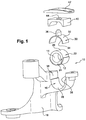
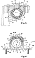
- FIG. 1 We have shown on figures 1 , 2 , and 6 a hinge bearing assembly 10 for an anti-roll bar (not shown) of a motor vehicle suspension on a body structure element (not shown) of said motor vehicle.
- the assembly 10 comprises at least one tubular substantially cylindrical elastomeric element 12 having an internal bore 14 which is crossed by the anti-roll bar (not shown).
- the elastomeric element 12 is received in a U-shaped housing 16 which is integral with the body structure element.
- the housing 16 can be made in a casting element 18 integral with the body structure element, as shown in FIG. figure 1 , or in a machined element attached to a body structure element of the vehicle, as shown in FIG. figure 6 .
- an outer surface 22 of the elastomer element 12 has a first half 24 which is received in a concave bottom surface 28 of the U-shaped housing 16 and a second half 26 which receives an immobilizing flange 42 in said housing 16.
- the elastomeric element 12 is simply threaded onto the anti-roll bar and then clamped in the housing 16 of the body structure element using the flange 42.
- the invention proposes a hinge bearing assembly 10 allowing a limited rotation of the anti-roll bar prior to its attachment, then preventing its free rotation after fixing, to avoid interference of the anti-roll bar with other bodies during the assembly of a motor vehicle.
- the invention proposes a hinge bearing assembly 10 of the type described above, characterized in that the elastomer element 12 is bonded to the anti-roll bar and in that the assembly 10 comprises means for mounting allowing limited rotation in both directions of the bar.
- these mounting means comprise at least one rotational support member 30 consisting of a semi-cylindrical part 32 which has an inner bearing surface 34 which is bonded to the second half 26 of the outer bearing surface 22 of the elastomer element 12.
- the rotational support member 30 comprises a protruding portion 36 carried by an outer bearing surface of the semi-cylindrical portion 32, which allows a limited determined angular displacement of the elastomeric element 12 between parallel walls 38 of the housing "U” during the establishment of the anti-roll bar and the elastomeric element 12 in the housing 16.
- the mounting means also comprise a compression wedge 40, which is capable of being indexed according to a determined angular position on the element 30 to assist in maintaining rotation and to be received simultaneously without play between the parallel walls 38 of the housing. "U”.
- the mounting means comprise an immobilizing flange 42 which is able to cover the compression shim 40 and to tighten it in the U-shaped housing 16 against the elastomer element 12 to immobilize the elastomer element 12 in rotation after the placing the anti-roll bar and the elastomeric element 12 in the housing 16.
- the holding aid member 30 permits a defined limited angular displacement of the elastomeric element 12 between parallel walls 38 of the "U" -shaped housing during the installation of the anti-roll bar and of the elastomer element 12 in the housing 16 as long as the compression shim 40 is not mounted.
- the projecting portion 36 comprises a finger 36 which protrudes radially from the outer bearing surface of the rotational support member 30.
- This configuration substantially allows a clearance of an angle " ⁇ " of about 35 ° on either side of a middle position of the finger between the parallel walls 38.
- the projecting portion 36 comprises a key 36 which protrudes radially from the outer surface of the element 30 to help maintain rotation transversely with respect to its axis "A".
- This configuration substantially allows a clearance of a smaller angle " ⁇ ", of about 20 ° on either side of a median rest position of the key 36 between the parallel walls 38.
- the compression wedge 40 furthermore comprises at least one complementary housing 44 of the portion 36 projecting from the support element 30.
- This housing is adapted to receive said projecting portion 36 to allow angular indexing of said shim 40 of compression on the element 30 to help maintain rotation.
- This housing has been shown only with reference to the first embodiment of the figures 1 and 5 , but it will be understood that there is provided such a housing for all embodiments of the invention.
- the finger 36 passes through a bore 44 of the compression wedge forming the complementary housing. It will be noted that the finger 36 also passes through a bore 46 of the flange 42.
- the key 36 is received in a complementary housing (not shown) of the compression wedge.
- the U-shaped housing 16 is formed in a casting element 18 which is integral with the body structure element.
- the housing 16 has a semi-cylindrical bottom surface 28 receiving the first half 24 of the outer cylindrical surface of the elastomeric element 12, the immobilizing flange 42 consisting of a plate which is fixed transversely to the element of foundry 18 so as to close the U-shaped housing.
- the U-shaped housing 16 is formed in an upper face 46 of a machined element 20 which has a lower bearing surface 48 on the body structure element (not shown).
- the housing 16 has a concave bottom surface 28 complementary to the first half 24 of the outer surface of the elastomeric element 12.
- the immobilization flange 42B consists of a horseshoe-shaped rider having a concave housing 50 and parallel arms 52 receiving the compression shim 40.
- Transverse branches 54 arranged at the end of the arms 52 are fixed on the body structure element.
- the transverse branches 54 comprise holes 56 which are traversed by screws 58 which are received in the body structure element.
- the flange 42B also allows the fixing of the machined element 20.
- the machined element 20 has a transverse space corresponding to the spacing of the arms 52 of the flange 42B, to allow attachment of the machined member 20 to the body structure member via the flange 42B.
- the first half 24 of the outer cylindrical surface of the elastomeric element 12 comprises a flat 60 complementary to a flat 62 formed in the concavity 28 of the machined element.
- the second half 26 of the outer cylindrical surface of the elastomeric element 12 comprises a flat 64 complementary to a flat portion 66 formed in the element 22 to help maintain rotation, which is itself complementary to a corresponding flat 68 formed in the wedge 40 compression.
- This configuration makes it possible to prohibit the rotation of the element 12 made of elastomeric material once the compression shim 40 has been mounted.
- the invention therefore proposes a hinge bearing assembly of an anti-roll bar for secure pre-assembly during assembly of the motor vehicle on which it must be mounted.
Landscapes
- Engineering & Computer Science (AREA)
- General Engineering & Computer Science (AREA)
- Mechanical Engineering (AREA)
- Health & Medical Sciences (AREA)
- Child & Adolescent Psychology (AREA)
- Vibration Prevention Devices (AREA)
- Support Of The Bearing (AREA)
- Springs (AREA)
Claims (10)
- Schwenklagereinheit (10) eines Querstabilisators einer Aufhängung eines Kraftfahrzeugs an einem Karosserie-Strukturelement des Kraftfahrzeugs, die mindestens ein rohrförmiges, im Wesentlichen zylindrisches Elastomerelement (12) enthält, das eine Innenbohrung (14) aufweist, die vom Querstabilisator durchquert wird, und das in einer U-förmigen Aufnahme (16) aufgenommen wird, die fest mit dem Karosserie-Strukturelement verbunden ist, wobei eine Außenauflagefläche (22) des Elastomerelements (12) eine erste Hälfte (24), die in einer konkaven Bodenauflagefläche (28) der U-förmigen Aufnahme (16) aufgenommen wird, und eine zweite Hälfte (26) aufweist, die einen Flansch (42) zur Fixierung in der Aufnahme (16) aufnimmt, dadurch gekennzeichnet, dass das Elastomerelement (12) auf den Querstabilisator geklebt wird, und dass die Einheit (10) eine begrenzte Drehung des Stabilisators erlaubende Montageeinrichtungen aufweist, die mindestens aufweisen:- ein Drehhalt-Unterstützungselement (30), das einen im Wesentlichen halbzylindrischen Teil (32) enthält, der eine Innenauflagefläche (34) aufweist, die auf die zweite Hälfte (26) der Außenauflagefläche (22) des Elastomerelements (12) geklebt wird, und das einen vorstehenden Teil (36) aufweist, der von einer Außenauflagefläche des halbzylindrischen Teils (32) getragen wird, der einen begrenzten bestimmten Winkelausschlag des Elastomerelements (12) zwischen parallelen Wänden (38) der U-förmigen Aufnahme während des Einsetzens des Querstabilisators und des Elastomerelements (12) in die Aufnahme (16) erlaubt,- einen Komprimierungskeil (40), der gemäß einer bestimmten Winkelstellung auf dem Drehhalt-Unterstützungselement (30) indexiert und gleichzeitig ohne Spiel zwischen den parallelen Wänden (38) der U-förmigen Aufnahme aufgenommen werden kann,- einen Fixierungsflansch (42), der den Komprimierungskeil (40) überdecken und ihn in der U-förmigen Aufnahme (16) gegen das Elastomerelement (12) drücken kann, um das Elastomerelement (12) nach dem Einsetzen des Querstabilisators und des Elastomerelements (12) in die Aufnahme (16) in Drehung zu fixieren.
- Lagereinheit (10) nach dem vorhergehenden Anspruch, dadurch gekennzeichnet, dass der Komprimierungskeil (40) mindestens eine zum vorstehenden Teil komplementäre Aufnahme (44) aufweist, die den vorstehenden Teil (36) aufnehmen kann, um die Winkelindexierung des Komprimierungskeils (40) auf dem Drehhalt-Unterstützungselement (30) zu ermöglichen.
- Lagereinheit (10) nach dem vorhergehenden Anspruch, dadurch gekennzeichnet, dass der vorstehende Teil (36) einen Finger aufweist, der radial ausgehend von der Außenauflagefläche des Drehhalt-Unterstützungselements (30) vorsteht, und der eine die komplementäre Aufnahme bildende Bohrung (44) des Komprimierungskeils (40) und dann eine Bohrung (46) des Flanschs (42) durchquert.
- Lagereinheit (10) nach Anspruch 2, dadurch gekennzeichnet, dass der vorstehende Teil (36) einen Spannkeil (36) aufweist, der radial ausgehend von der Außenauflagefläche des Drehhaltunterstützungselements (30) quer bezüglich seiner Achse (A) vorsteht, und der in einer komplementären Aufnahme des Komprimierungskeils (40) aufgenommen wird.
- Lagereinheit (10) nach einem der Ansprüche 1 bis 4, dadurch gekennzeichnet, dass die U-förmige Aufnahme (16) in einem fest mit dem Karosserie-Strukturelement verbundenen Gusselement (18) ausgebildet ist, und dass sie eine halbzylindrische Bodenauflagefläche (28) aufweist, die die erste Hälfte (24) der äußeren zylindrischen Auflagefläche des Elastomerelements aufnimmt, wobei der Fixierungsflansch (42) aus einer Platte besteht, die quer am Gusselement (18) befestigt ist, um die U-förmige Aufnahme (16) zu verschließen.
- Lagereinheit (10) nach einem der Ansprüche 1 bis 4, dadurch gekennzeichnet, dass die U-förmige Aufnahme (16) in einer Oberseite (46) eines maschinell bearbeiteten Elements (20) ausgebildet ist, das eine untere Auflageseite (48) auf dem Karosserie-Strukturelement aufweist, und dass sie eine konkave Bodenauflagefläche (28) aufweist, die zur ersten Hälfte (24) der Außenauflagefläche des Elastomerelements (12) komplementär ist, wobei der Fixierungsflansch (42B) aus einer hufeisenförmigen Krampe besteht, die eine konkave Aufnahme (50) und parallele Schenkel (52) enthält, die den Komprimierungskeil (40) aufnehmen, wobei die Schenkel an ihren Enden Querarme (54) aufweisen, die an dem Karosserie-Strukturelement befestigt werden können.
- Lagereinheit (10) nach dem vorhergehenden Anspruch, dadurch gekennzeichnet, dass die Querarme (54) Bohrungen (54) aufweisen, die von Schrauben (58) durchquert werden, die im Karosserie-Strukturelement aufgenommen werden, um die Befestigung des Flanschs (42) am Karosserie-Strukturelement zu ermöglichen.
- Lagereinheit (10) nach einem der Ansprüche 6 oder 7, dadurch gekennzeichnet, dass das maschinell bearbeitete Element (20) eine Querabmessung aufweist, die dem Spreizen der Schenkel (52) des Flanschs (40) entspricht, um die Befestigung des maschinell bearbeiteten Elements (20) am Karosserie-Strukturelement mit Hilfe des Flanschs (40) zu ermöglichen.
- Lagereinheit (10) nach einem der Ansprüche 5 bis 8, dadurch gekennzeichnet, dass die erste Hälfte (24) der äußeren zylindrischen Auflagefläche des Elastomerelements (12) eine Abflachung (60) komplementär zu einer Abflachung (62) aufweist, die in der Konkavität (28) des maschinell bearbeiteten Elements ausgebildet ist.
- Lagereinheit (10) nach einem der Ansprüche 5 bis 8, dadurch gekennzeichnet, dass die zweite Hälfte (26) der äußeren zylindrischen Auflagefläche des Elastomerelements eine Abflachung (64) komplementär zu einer Abflachung (66), die im Drehhaltunterstützungselement (30) ausgebildet ist, und zu einer entsprechenden Abflachung (68) aufweist, die im Komprimierungskeil (40) ausgebildet ist.
Applications Claiming Priority (2)
| Application Number | Priority Date | Filing Date | Title |
|---|---|---|---|
| FR1254912A FR2991236B1 (fr) | 2012-05-29 | 2012-05-29 | "ensemble de palier d'articulation pour une barre anti-devers" |
| PCT/FR2013/050922 WO2013178896A1 (fr) | 2012-05-29 | 2013-04-25 | Ensemble de palier d'articulation pour une barre anti-devers |
Publications (2)
| Publication Number | Publication Date |
|---|---|
| EP2855178A1 EP2855178A1 (de) | 2015-04-08 |
| EP2855178B1 true EP2855178B1 (de) | 2016-04-20 |
Family
ID=48468638
Family Applications (1)
| Application Number | Title | Priority Date | Filing Date |
|---|---|---|---|
| EP13723872.1A Not-in-force EP2855178B1 (de) | 2012-05-29 | 2013-04-25 | Schwenkbare lageranordnung für einen stabilisator |
Country Status (3)
| Country | Link |
|---|---|
| EP (1) | EP2855178B1 (de) |
| FR (1) | FR2991236B1 (de) |
| WO (1) | WO2013178896A1 (de) |
Cited By (2)
| Publication number | Priority date | Publication date | Assignee | Title |
|---|---|---|---|---|
| EP3530500A1 (de) * | 2018-02-26 | 2019-08-28 | Sumitomo Riko Company Limited | Stabilisatorbuchse zur haftverwendung und mit der stabilisatorbuchse ausgestattete stabilisatorstange |
| FR3164151A1 (fr) * | 2024-07-05 | 2026-01-09 | Stellantis Auto Sas | Corne de berceau intégrant une cale de suspension pour groupe électromoteur de véhicule automobile |
Families Citing this family (5)
| Publication number | Priority date | Publication date | Assignee | Title |
|---|---|---|---|---|
| FR3000009B1 (fr) | 2012-12-20 | 2018-08-03 | Renault S.A.S. | Dispositif de liaison d'un berceau automobile |
| JP6179381B2 (ja) * | 2013-12-09 | 2017-08-16 | 三菱自動車工業株式会社 | スタビライザーの取付構造 |
| KR101766111B1 (ko) * | 2016-01-19 | 2017-08-07 | 현대자동차주식회사 | 내부 구성요소의 회전이 가능한 부시와 이를 구비한 스태빌라이저 바 어셈블리 |
| JP6596350B2 (ja) * | 2016-02-15 | 2019-10-23 | 住友理工株式会社 | スタビライザブッシュ |
| US11787257B2 (en) * | 2021-06-08 | 2023-10-17 | Jerry A. Edwards | Torsion bushings and related assemblies |
Citations (1)
| Publication number | Priority date | Publication date | Assignee | Title |
|---|---|---|---|---|
| US20040070161A1 (en) * | 2002-10-15 | 2004-04-15 | Fader Joseph A. | Stabilizer bar with bushings that remain fixed to the bar |
Family Cites Families (9)
| Publication number | Priority date | Publication date | Assignee | Title |
|---|---|---|---|---|
| FR2615458B1 (fr) * | 1987-05-19 | 1991-06-21 | Peugeot | Traverse avant pour vehicule automobile |
| JP3047501B2 (ja) * | 1991-04-15 | 2000-05-29 | 豊田合成株式会社 | 筒状防振ブッシュ |
| JPH08244431A (ja) * | 1995-03-09 | 1996-09-24 | Tokai Rubber Ind Ltd | スタビライザバー用ブッシュ |
| FR2756779B1 (fr) * | 1996-12-11 | 1999-03-05 | Peugeot | Dispositif de suspension pour un train de roues de vehicule automobile |
| JPH10217741A (ja) * | 1997-02-10 | 1998-08-18 | Nissan Motor Co Ltd | サスペンションサブフレーム構造 |
| FR2806035B1 (fr) * | 2000-03-08 | 2002-06-14 | Peugeot Citroen Automobiles Sa | Dispositif de fixation d'une barre anti-devers d'un vehicule automobile a la caisse de celui-ci |
| WO2006008803A1 (ja) * | 2004-07-20 | 2006-01-26 | Toyo Tire & Rubber Co., Ltd. | スタビライザブッシュ |
| DE102004056884B4 (de) * | 2004-11-25 | 2007-11-22 | Vorwerk Autotec Gmbh & Co.Kg | Lager, insbesondere Gummi/Metall-Lager zur Anlenkung eines Stabilisators an einem Kraftfahrzeug |
| DE102006032826A1 (de) * | 2006-07-14 | 2008-01-17 | Carl Freudenberg Kg | Stabilisator zur Anlenkung einer Stabilisatorstange an einem Kraftfahrzeug |
-
2012
- 2012-05-29 FR FR1254912A patent/FR2991236B1/fr not_active Expired - Fee Related
-
2013
- 2013-04-25 WO PCT/FR2013/050922 patent/WO2013178896A1/fr not_active Ceased
- 2013-04-25 EP EP13723872.1A patent/EP2855178B1/de not_active Not-in-force
Patent Citations (1)
| Publication number | Priority date | Publication date | Assignee | Title |
|---|---|---|---|---|
| US20040070161A1 (en) * | 2002-10-15 | 2004-04-15 | Fader Joseph A. | Stabilizer bar with bushings that remain fixed to the bar |
Cited By (4)
| Publication number | Priority date | Publication date | Assignee | Title |
|---|---|---|---|---|
| EP3530500A1 (de) * | 2018-02-26 | 2019-08-28 | Sumitomo Riko Company Limited | Stabilisatorbuchse zur haftverwendung und mit der stabilisatorbuchse ausgestattete stabilisatorstange |
| CN110195754A (zh) * | 2018-02-26 | 2019-09-03 | 住友理工株式会社 | 粘接用稳定器衬套以及带稳定器衬套的稳定器杆 |
| US10994583B2 (en) | 2018-02-26 | 2021-05-04 | Sumitomo Riko Company Limited | Stabilizer bushing for adhesive use and stabilizer bar equipped with stabilizer bushing |
| FR3164151A1 (fr) * | 2024-07-05 | 2026-01-09 | Stellantis Auto Sas | Corne de berceau intégrant une cale de suspension pour groupe électromoteur de véhicule automobile |
Also Published As
| Publication number | Publication date |
|---|---|
| WO2013178896A1 (fr) | 2013-12-05 |
| FR2991236B1 (fr) | 2014-06-13 |
| EP2855178A1 (de) | 2015-04-08 |
| FR2991236A1 (fr) | 2013-12-06 |
Similar Documents
| Publication | Publication Date | Title |
|---|---|---|
| EP2855178B1 (de) | Schwenkbare lageranordnung für einen stabilisator | |
| FR2943746A1 (fr) | Collier de serrage et dispositif de roulage a plat l'incorporant | |
| FR2840966A1 (fr) | Gaine pour ressort de suspension | |
| EP2814640A1 (de) | Werkzeuge zur montage eines aufhängefederblatts am chassis und an den radbefestigungen eines fahrwerks eines kraftfahrzeugs und entfernen derselben | |
| FR2900605A1 (fr) | Procede de fabrication d'un mecanisme d'articulation pour siege de vehicule, mecanisme d'articulation fabrique selon un tel procede et siege de vehicule comprenant un tel mecanisme d'articulation | |
| FR2901737A1 (fr) | Dispositif de butee de suspension et jambe de force | |
| EP0309344A1 (de) | Verbindungsvorrichtung für eine Lenksäule und ein mit dieser Vorrichtung ausgestattetes Fahrzeug | |
| WO2012143474A1 (fr) | Système de connexion pour la fixation d'un dispositif de portage | |
| FR2810275A1 (fr) | Dispositif de fixation d'un support de palier d'une barre anti-devers a un element de structure d'un vehicule automobile | |
| FR3100773A1 (fr) | aménagement de parechoc pour véhicule automobile | |
| FR2928982A1 (fr) | Piece de frottement et ensemble support de pieces de frottement pour un assemblage de deux elements | |
| EP4011714B1 (de) | Vorrichtung zum einhaken eines sicherheitsgurtschlosses | |
| FR3100772A1 (fr) | aménagement de parechoc pour véhicule automobile | |
| EP1721795B1 (de) | Vorrichtung sowie Verfahren zur Befestigung eines Scheibenwischermechanismus auf einem Fahrzeugkarosserieteil, und Kraftfahrzeug mit einer solchen Vorrichtung | |
| EP1765652B1 (de) | Stützanordnung für ein kraftfahrzeugrad | |
| EP1378639A1 (de) | Elastische Aufhängung für die Abgasanlage eines Kraftfahrzeuges und Kraftfahrzeug mit einer solchen Aufhängung | |
| FR2868031A1 (fr) | Entretoise a montage sans soudures pour berceau de support de train avant ou arriere d'un vehicule automobile | |
| EP0184780B1 (de) | Befestigung für Schwingungsdämpferstange | |
| FR3029162A1 (fr) | Agencement pour vehicule automobile muni d'une entretoise ajustable disposee entre deux elements de structure | |
| EP3362304B1 (de) | Anordnung zur verbindung eines achsschenkels mit einem strukturelement eines kraftfahrzeugs | |
| WO2002040220A1 (fr) | Procede et dispositif de montage et demontage d'un systeme de suspension | |
| FR3101280A1 (fr) | ELEMENT DE SUSPENSION comportant une aide au positionnement DE MOYENS DE FIXATION d’une barre lors de l’assemblage du vehicule | |
| EP3356190B1 (de) | Anordnung einer verkleidung einses steuerhebels | |
| FR3135043A1 (fr) | Ensemble de connexion d’un système d’essuyage. | |
| WO2021048479A1 (fr) | Aménagement de parechoc pour véhicule automobile |
Legal Events
| Date | Code | Title | Description |
|---|---|---|---|
| PUAI | Public reference made under article 153(3) epc to a published international application that has entered the european phase |
Free format text: ORIGINAL CODE: 0009012 |
|
| 17P | Request for examination filed |
Effective date: 20141016 |
|
| AK | Designated contracting states |
Kind code of ref document: A1 Designated state(s): AL AT BE BG CH CY CZ DE DK EE ES FI FR GB GR HR HU IE IS IT LI LT LU LV MC MK MT NL NO PL PT RO RS SE SI SK SM TR |
|
| AX | Request for extension of the european patent |
Extension state: BA ME |
|
| DAX | Request for extension of the european patent (deleted) | ||
| GRAP | Despatch of communication of intention to grant a patent |
Free format text: ORIGINAL CODE: EPIDOSNIGR1 |
|
| INTG | Intention to grant announced |
Effective date: 20151218 |
|
| GRAS | Grant fee paid |
Free format text: ORIGINAL CODE: EPIDOSNIGR3 |
|
| GRAA | (expected) grant |
Free format text: ORIGINAL CODE: 0009210 |
|
| AK | Designated contracting states |
Kind code of ref document: B1 Designated state(s): AL AT BE BG CH CY CZ DE DK EE ES FI FR GB GR HR HU IE IS IT LI LT LU LV MC MK MT NL NO PL PT RO RS SE SI SK SM TR |
|
| REG | Reference to a national code |
Ref country code: GB Ref legal event code: FG4D Free format text: NOT ENGLISH |
|
| REG | Reference to a national code |
Ref country code: FR Ref legal event code: PLFP Year of fee payment: 4 |
|
| REG | Reference to a national code |
Ref country code: CH Ref legal event code: EP |
|
| REG | Reference to a national code |
Ref country code: AT Ref legal event code: REF Ref document number: 792003 Country of ref document: AT Kind code of ref document: T Effective date: 20160515 |
|
| REG | Reference to a national code |
Ref country code: IE Ref legal event code: FG4D Free format text: LANGUAGE OF EP DOCUMENT: FRENCH |
|
| REG | Reference to a national code |
Ref country code: DE Ref legal event code: R096 Ref document number: 602013006780 Country of ref document: DE |
|
| REG | Reference to a national code |
Ref country code: LT Ref legal event code: MG4D |
|
| PG25 | Lapsed in a contracting state [announced via postgrant information from national office to epo] |
Ref country code: BE Free format text: LAPSE BECAUSE OF NON-PAYMENT OF DUE FEES Effective date: 20160430 |
|
| REG | Reference to a national code |
Ref country code: AT Ref legal event code: MK05 Ref document number: 792003 Country of ref document: AT Kind code of ref document: T Effective date: 20160420 |
|
| REG | Reference to a national code |
Ref country code: NL Ref legal event code: MP Effective date: 20160420 |
|
| PG25 | Lapsed in a contracting state [announced via postgrant information from national office to epo] |
Ref country code: NL Free format text: LAPSE BECAUSE OF FAILURE TO SUBMIT A TRANSLATION OF THE DESCRIPTION OR TO PAY THE FEE WITHIN THE PRESCRIBED TIME-LIMIT Effective date: 20160420 Ref country code: NO Free format text: LAPSE BECAUSE OF FAILURE TO SUBMIT A TRANSLATION OF THE DESCRIPTION OR TO PAY THE FEE WITHIN THE PRESCRIBED TIME-LIMIT Effective date: 20160720 Ref country code: PL Free format text: LAPSE BECAUSE OF FAILURE TO SUBMIT A TRANSLATION OF THE DESCRIPTION OR TO PAY THE FEE WITHIN THE PRESCRIBED TIME-LIMIT Effective date: 20160420 Ref country code: LT Free format text: LAPSE BECAUSE OF FAILURE TO SUBMIT A TRANSLATION OF THE DESCRIPTION OR TO PAY THE FEE WITHIN THE PRESCRIBED TIME-LIMIT Effective date: 20160420 Ref country code: FI Free format text: LAPSE BECAUSE OF FAILURE TO SUBMIT A TRANSLATION OF THE DESCRIPTION OR TO PAY THE FEE WITHIN THE PRESCRIBED TIME-LIMIT Effective date: 20160420 |
|
| PG25 | Lapsed in a contracting state [announced via postgrant information from national office to epo] |
Ref country code: PT Free format text: LAPSE BECAUSE OF FAILURE TO SUBMIT A TRANSLATION OF THE DESCRIPTION OR TO PAY THE FEE WITHIN THE PRESCRIBED TIME-LIMIT Effective date: 20160822 Ref country code: SE Free format text: LAPSE BECAUSE OF FAILURE TO SUBMIT A TRANSLATION OF THE DESCRIPTION OR TO PAY THE FEE WITHIN THE PRESCRIBED TIME-LIMIT Effective date: 20160420 Ref country code: LV Free format text: LAPSE BECAUSE OF FAILURE TO SUBMIT A TRANSLATION OF THE DESCRIPTION OR TO PAY THE FEE WITHIN THE PRESCRIBED TIME-LIMIT Effective date: 20160420 Ref country code: HR Free format text: LAPSE BECAUSE OF FAILURE TO SUBMIT A TRANSLATION OF THE DESCRIPTION OR TO PAY THE FEE WITHIN THE PRESCRIBED TIME-LIMIT Effective date: 20160420 Ref country code: AT Free format text: LAPSE BECAUSE OF FAILURE TO SUBMIT A TRANSLATION OF THE DESCRIPTION OR TO PAY THE FEE WITHIN THE PRESCRIBED TIME-LIMIT Effective date: 20160420 Ref country code: RS Free format text: LAPSE BECAUSE OF FAILURE TO SUBMIT A TRANSLATION OF THE DESCRIPTION OR TO PAY THE FEE WITHIN THE PRESCRIBED TIME-LIMIT Effective date: 20160420 Ref country code: ES Free format text: LAPSE BECAUSE OF FAILURE TO SUBMIT A TRANSLATION OF THE DESCRIPTION OR TO PAY THE FEE WITHIN THE PRESCRIBED TIME-LIMIT Effective date: 20160420 Ref country code: GR Free format text: LAPSE BECAUSE OF FAILURE TO SUBMIT A TRANSLATION OF THE DESCRIPTION OR TO PAY THE FEE WITHIN THE PRESCRIBED TIME-LIMIT Effective date: 20160721 |
|
| REG | Reference to a national code |
Ref country code: CH Ref legal event code: PL |
|
| PG25 | Lapsed in a contracting state [announced via postgrant information from national office to epo] |
Ref country code: IT Free format text: LAPSE BECAUSE OF FAILURE TO SUBMIT A TRANSLATION OF THE DESCRIPTION OR TO PAY THE FEE WITHIN THE PRESCRIBED TIME-LIMIT Effective date: 20160420 |
|
| REG | Reference to a national code |
Ref country code: DE Ref legal event code: R097 Ref document number: 602013006780 Country of ref document: DE |
|
| REG | Reference to a national code |
Ref country code: IE Ref legal event code: MM4A |
|
| PG25 | Lapsed in a contracting state [announced via postgrant information from national office to epo] |
Ref country code: CH Free format text: LAPSE BECAUSE OF NON-PAYMENT OF DUE FEES Effective date: 20160430 Ref country code: DK Free format text: LAPSE BECAUSE OF FAILURE TO SUBMIT A TRANSLATION OF THE DESCRIPTION OR TO PAY THE FEE WITHIN THE PRESCRIBED TIME-LIMIT Effective date: 20160420 Ref country code: LI Free format text: LAPSE BECAUSE OF NON-PAYMENT OF DUE FEES Effective date: 20160430 Ref country code: CZ Free format text: LAPSE BECAUSE OF FAILURE TO SUBMIT A TRANSLATION OF THE DESCRIPTION OR TO PAY THE FEE WITHIN THE PRESCRIBED TIME-LIMIT Effective date: 20160420 Ref country code: SK Free format text: LAPSE BECAUSE OF FAILURE TO SUBMIT A TRANSLATION OF THE DESCRIPTION OR TO PAY THE FEE WITHIN THE PRESCRIBED TIME-LIMIT Effective date: 20160420 Ref country code: EE Free format text: LAPSE BECAUSE OF FAILURE TO SUBMIT A TRANSLATION OF THE DESCRIPTION OR TO PAY THE FEE WITHIN THE PRESCRIBED TIME-LIMIT Effective date: 20160420 Ref country code: RO Free format text: LAPSE BECAUSE OF FAILURE TO SUBMIT A TRANSLATION OF THE DESCRIPTION OR TO PAY THE FEE WITHIN THE PRESCRIBED TIME-LIMIT Effective date: 20160420 Ref country code: MC Free format text: LAPSE BECAUSE OF FAILURE TO SUBMIT A TRANSLATION OF THE DESCRIPTION OR TO PAY THE FEE WITHIN THE PRESCRIBED TIME-LIMIT Effective date: 20160420 |
|
| PLBE | No opposition filed within time limit |
Free format text: ORIGINAL CODE: 0009261 |
|
| STAA | Information on the status of an ep patent application or granted ep patent |
Free format text: STATUS: NO OPPOSITION FILED WITHIN TIME LIMIT |
|
| PG25 | Lapsed in a contracting state [announced via postgrant information from national office to epo] |
Ref country code: SM Free format text: LAPSE BECAUSE OF FAILURE TO SUBMIT A TRANSLATION OF THE DESCRIPTION OR TO PAY THE FEE WITHIN THE PRESCRIBED TIME-LIMIT Effective date: 20160420 |
|
| 26N | No opposition filed |
Effective date: 20170123 |
|
| REG | Reference to a national code |
Ref country code: FR Ref legal event code: PLFP Year of fee payment: 5 |
|
| PG25 | Lapsed in a contracting state [announced via postgrant information from national office to epo] |
Ref country code: IE Free format text: LAPSE BECAUSE OF NON-PAYMENT OF DUE FEES Effective date: 20160425 Ref country code: SI Free format text: LAPSE BECAUSE OF FAILURE TO SUBMIT A TRANSLATION OF THE DESCRIPTION OR TO PAY THE FEE WITHIN THE PRESCRIBED TIME-LIMIT Effective date: 20160420 |
|
| REG | Reference to a national code |
Ref country code: FR Ref legal event code: PLFP Year of fee payment: 6 |
|
| PG25 | Lapsed in a contracting state [announced via postgrant information from national office to epo] |
Ref country code: HU Free format text: LAPSE BECAUSE OF FAILURE TO SUBMIT A TRANSLATION OF THE DESCRIPTION OR TO PAY THE FEE WITHIN THE PRESCRIBED TIME-LIMIT; INVALID AB INITIO Effective date: 20130425 |
|
| PG25 | Lapsed in a contracting state [announced via postgrant information from national office to epo] |
Ref country code: MT Free format text: LAPSE BECAUSE OF FAILURE TO SUBMIT A TRANSLATION OF THE DESCRIPTION OR TO PAY THE FEE WITHIN THE PRESCRIBED TIME-LIMIT Effective date: 20160420 Ref country code: MK Free format text: LAPSE BECAUSE OF FAILURE TO SUBMIT A TRANSLATION OF THE DESCRIPTION OR TO PAY THE FEE WITHIN THE PRESCRIBED TIME-LIMIT Effective date: 20160420 Ref country code: IS Free format text: LAPSE BECAUSE OF FAILURE TO SUBMIT A TRANSLATION OF THE DESCRIPTION OR TO PAY THE FEE WITHIN THE PRESCRIBED TIME-LIMIT Effective date: 20160420 Ref country code: LU Free format text: LAPSE BECAUSE OF NON-PAYMENT OF DUE FEES Effective date: 20160425 Ref country code: CY Free format text: LAPSE BECAUSE OF FAILURE TO SUBMIT A TRANSLATION OF THE DESCRIPTION OR TO PAY THE FEE WITHIN THE PRESCRIBED TIME-LIMIT Effective date: 20160420 |
|
| PG25 | Lapsed in a contracting state [announced via postgrant information from national office to epo] |
Ref country code: BG Free format text: LAPSE BECAUSE OF FAILURE TO SUBMIT A TRANSLATION OF THE DESCRIPTION OR TO PAY THE FEE WITHIN THE PRESCRIBED TIME-LIMIT Effective date: 20160420 |
|
| PG25 | Lapsed in a contracting state [announced via postgrant information from national office to epo] |
Ref country code: TR Free format text: LAPSE BECAUSE OF FAILURE TO SUBMIT A TRANSLATION OF THE DESCRIPTION OR TO PAY THE FEE WITHIN THE PRESCRIBED TIME-LIMIT Effective date: 20160420 Ref country code: AL Free format text: LAPSE BECAUSE OF FAILURE TO SUBMIT A TRANSLATION OF THE DESCRIPTION OR TO PAY THE FEE WITHIN THE PRESCRIBED TIME-LIMIT Effective date: 20160420 |
|
| PGFP | Annual fee paid to national office [announced via postgrant information from national office to epo] |
Ref country code: GB Payment date: 20220425 Year of fee payment: 10 Ref country code: FR Payment date: 20220421 Year of fee payment: 10 Ref country code: DE Payment date: 20220420 Year of fee payment: 10 |
|
| P01 | Opt-out of the competence of the unified patent court (upc) registered |
Effective date: 20230608 |
|
| REG | Reference to a national code |
Ref country code: DE Ref legal event code: R119 Ref document number: 602013006780 Country of ref document: DE |
|
| GBPC | Gb: european patent ceased through non-payment of renewal fee |
Effective date: 20230425 |
|
| PG25 | Lapsed in a contracting state [announced via postgrant information from national office to epo] |
Ref country code: GB Free format text: LAPSE BECAUSE OF NON-PAYMENT OF DUE FEES Effective date: 20230425 |
|
| PG25 | Lapsed in a contracting state [announced via postgrant information from national office to epo] |
Ref country code: GB Free format text: LAPSE BECAUSE OF NON-PAYMENT OF DUE FEES Effective date: 20230425 Ref country code: FR Free format text: LAPSE BECAUSE OF NON-PAYMENT OF DUE FEES Effective date: 20230430 Ref country code: DE Free format text: LAPSE BECAUSE OF NON-PAYMENT OF DUE FEES Effective date: 20231103 |