EP2856031B1 - Brûleur à faible taux d'émission de nox et procédé de fonctionnement d'un brûleur à faible taux d'émission en nox - Google Patents
Brûleur à faible taux d'émission de nox et procédé de fonctionnement d'un brûleur à faible taux d'émission en nox Download PDFInfo
- Publication number
- EP2856031B1 EP2856031B1 EP13796709.7A EP13796709A EP2856031B1 EP 2856031 B1 EP2856031 B1 EP 2856031B1 EP 13796709 A EP13796709 A EP 13796709A EP 2856031 B1 EP2856031 B1 EP 2856031B1
- Authority
- EP
- European Patent Office
- Prior art keywords
- flame holder
- voltage
- fuel
- conductive
- conductive flame
- Prior art date
- Legal status (The legal status is an assumption and is not a legal conclusion. Google has not performed a legal analysis and makes no representation as to the accuracy of the status listed.)
- Not-in-force
Links
Images


Classifications
-
- F—MECHANICAL ENGINEERING; LIGHTING; HEATING; WEAPONS; BLASTING
- F23—COMBUSTION APPARATUS; COMBUSTION PROCESSES
- F23C—METHODS OR APPARATUS FOR COMBUSTION USING FLUID FUEL OR SOLID FUEL SUSPENDED IN A CARRIER GAS OR AIR
- F23C99/00—Subject-matter not provided for in other groups of this subclass
- F23C99/001—Applying electric means or magnetism to combustion
-
- F—MECHANICAL ENGINEERING; LIGHTING; HEATING; WEAPONS; BLASTING
- F23—COMBUSTION APPARATUS; COMBUSTION PROCESSES
- F23D—BURNERS
- F23D11/00—Burners using a direct spraying action of liquid droplets or vaporised liquid into the combustion space
- F23D11/36—Details
- F23D11/40—Mixing tubes; Burner heads
- F23D11/406—Flame stabilising means, e.g. flame holders
-
- F—MECHANICAL ENGINEERING; LIGHTING; HEATING; WEAPONS; BLASTING
- F23—COMBUSTION APPARATUS; COMBUSTION PROCESSES
- F23D—BURNERS
- F23D14/00—Burners for combustion of a gas, e.g. of a gas stored under pressure as a liquid
- F23D14/02—Premix gas burners, i.e. in which gaseous fuel is mixed with combustion air upstream of the combustion zone
-
- F—MECHANICAL ENGINEERING; LIGHTING; HEATING; WEAPONS; BLASTING
- F23—COMBUSTION APPARATUS; COMBUSTION PROCESSES
- F23D—BURNERS
- F23D14/00—Burners for combustion of a gas, e.g. of a gas stored under pressure as a liquid
- F23D14/46—Details
- F23D14/72—Safety devices, e.g. operative in case of failure of gas supply
- F23D14/82—Preventing flashback or blowback
Definitions
- NOx The various oxides of nitrogen, known collectively as NOx, and often present primarily in the mono-oxide form NO, form a major component of air pollution including noxious photochemical smog.
- NOx is typically generated when nitrogen and oxygen in the air combine at high temperatures during the burning of fuel in internal combustion engines; gas turbines; industrial, commercial and residential burners; industrial, commercial, and residential boilers; and/or other combustion applications.
- US 2005/208442 A1 discloses a flame ionization detector and the application of AC electricity to a flame, resulting in a resonant circuit, and also discloses the application of microwaves to a burner arrangement.
- a low oxides of nitrogen (NOx) burner (p.2, para. 21), comprising a nozzle configured to produce a diverging fuel stream, and a conductive electrode supported proximate the nozzle at a position along the diverging fuel stream corresponding to a selected fuel concentration, oxygen concentration, fuel/oxygen stoichiometry, or combination thereof.
- a charge source is configured to impart an electric charge concentration on a flame.
- the imparted charge concentration is selected to cause the flame to remain ignited.
- US 2011/027734 A1 teaches three electrodes deployed circumferentially around a flame and the application of moving electric fields.
- US 2007/020 567 A1 teaches against direct contact of an electrode and a flame.
- DE 12 74 781 B discloses the application of AC fields to a flame, without direct contact as in US 2007/020567 A1 .
- CA 2 017 777 A1 shows electricity and magnetism applied in a flame region.
- Low NOx burners have been developed but may suffer from relatively high complexity and cost. Low NOx burners may further suffer from relatively poor flame stability and may be prone to flame blow-out. To overcome the tendency to undergo flame blow-out, low NOx burners may typically be operated under a relatively narrow range of turn-down ratios. Because of the effect of reduced turn-down ratio, low NOx burners may typically operate with relatively limited dynamic range with respect to power or heat output, which may be expressed as BTU/hour.
- a low NOx burner with greater simplicity and/or reduced cost compared to previous low NOx burners.
- a low NOx burner that exhibits improved flame stability and/or that is amenable to operation over a relatively wide dynamic range such as to provide load matching.
- a method of reducing the formation of oxides of nitrogen (NOx) evolved from a combustion reaction includes reducing the combustion temperature by operating near a fuel dilution limit.
- a low NOx burner includes a conductive flame holder supported proximate a diverging fuel stream at a distance along the diverging fuel stream corresponding to a desired fuel concentration, oxygen concentration, fuel/oxygen stoichiometry, or combination thereof.
- a charge source is configured to impart a charge concentration on a flame surface held by the conductive flame holder. The imparted charge concentration can be selected to cause the flame to remain ignited and in contact with the conductive flame holder.
- a method of operating a low NOx burner includes supporting a conductive flame holder proximate a diverging fuel stream at a selected distance along the diverging fuel stream and imparting a charge onto a flame held by the conductive flame holder and supported by the diverging fuel stream.
- the diverging fuel stream is supplied by a nozzle. Flame holding and flame ignition are maintained responsive to cooperation between the imparted charge on the flame and the conductive flame holder.
- a conductive flame holder in a low NOx burner, is supported at a distance from a fuel nozzle emitting a diverging fuel stream.
- the distance can be selected to correspond to a desired property of the fuel/air mixture, for example the flammability limit of the mixture.
- An electric charge source imparting a charge to the flame surface operates in cooperation with the conductive flame holder to cause the flame to remain ignited and in contact with the conductive flame holder. This allows the use of leaner fuel/air mixtures, reducing the flame temperature and lowering NOx production. Mixing of the fuel and air can be increased, further reducing NOx production.
- a sensor is used to monitor the flame condition.
- the position or configuration of the conductive flame holder is automatically or manually adjusted to maintain a desired flame condition.
- FIG. 1 is a cross-sectional view of portion of a low oxides of nitrogen (NOx) burner 101, according to an embodiment.
- the low NOx burner 101 includes a conductive flame holder 102 supported proximate the diverging fuel stream 104 at a distance X along the diverging fuel stream 104.
- the distance X corresponds to a desired fuel concentration, oxygen concentration, fuel and oxygen stoichiometry, or combination thereof.
- a charge source 106 is configured to impart a charge concentration on a flame surface 108 held by the conductive flame holder 102. The imparted charge concentration is selected to cause the flame to remain ignited and in contact with the conductive flame holder 102.
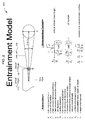
- the fuel stream 104 may diverge at a substantially constant angle from the fuel nozzle 110.
- the expansion in stream area corresponds to dilution of the fuel by entrainment of a surrounding fluid.
- the surrounding fluid can include air and/or recycled flue gas. If the surrounding fluid is air, for example, the entrained fluid is about 21% oxygen, 78% nitrogen, and a small amount of other gases. If the surrounding fluid includes a flue gas recycle, for example, the entrained fluid can include about 2% to 5% oxygen, about 78% nitrogen, and combustion products such as carbon dioxide, water vapor and other combustion products found in the flue gas. Recycling flue gas for entrainment with the fuel stream 104 can thus result in a lower concentration of oxygen mixed with the fuel.
- a flame 108 burned near a lean flammability limit can have a lower temperature than a flame burned richer, and can thus output less NOx than a flame burned richer.
- a flame 108 burned in a lower concentration of oxygen can output less NOx than a flame burned in a higher concentration of oxygen.
- a well-mixed flame 108 tends to output less NOx than a poorly-mixed flame.
- the distance X is selected to correspond to be at or slightly above a lean flammability limit of the fuel under the operating conditions.
- the application of charges to the flame 108 by the flame charge source 106 has been found to improve flame mixing. These effects cause the burner 101 to exhibit low NOx output.
- the distance x 0 is a function of the size D 0 of the aperture 111 in the fuel nozzle 110 through which the fuel stream 104 is emitted.
- the point 112 may be considered a virtual origin of the diverging fuel stream 104.
- the fuel becomes increasingly diluted by the entrainment of surrounding air, flue gas, or other fluid as the diverging fuel stream 104 proceeds from the fuel nozzle 110.
- the fuel mixture becomes increasingly lean with increasing distance from the fuel nozzle 110. If the fuel/oxidizer mixture becomes so lean that it will barely support combustion, it may be said that a lean flammability limit has been reached.
- the distance X includes a distance X E from the fuel nozzle 110 plus a distance x 0 to the virtual origin point 112 upstream from the fuel nozzle aperture 111, according to an embodiment.
- the distance X can, for example, correspond substantially to a lean flammability limit of the fuel in the diverging fuel stream 104.
- the angle of divergence of fuel stream 104 is a substantially 15-degree solid angle, alternatively referred to as a substantially 7.5-degree angle of divergence from an axis of fuel transport.
- the burner 101 can optionally also include an adjustable support (not shown) configured to change the distance X at which the conductive flame holder 102 is supported responsive to a change in the lean flammability limit or other operating parameter of the burner 101, according to an embodiment.
- An electronic control module (not shown) may be configured to select the distance X along the diverging fuel stream 104 at which the conductive flame holder 102 is supported.
- the conductive flame holder 102 is shaped to define an aperture corresponding at least approximately to a fuel stream diameter at the distance X.
- the conductive flame holder 102 includes a conductive ring.
- the conductive flame holder 102 can additionally or alternatively include a circular tension conductive structure.
- the conductive flame holder 102 can include a composite assembly configured to adapt the shape of the conductive flame holder 102 to a selected corresponding diverging fuel stream 104 diameter.
- the conductive flame holder 102 can include a plurality of conductive flame holders sized to correspond to respective selected diameters corresponding to the diverging fuel stream 104.
- the conductive flame holder 102 may include a sharp electrode.
- the conductive flame holder 102 may include a substantially dull electrode.
- the low-NOx burner 101 includes, operatively coupled to or forming a portion of the conductive flame holder 102, a node 114 having a selected voltage condition, according to an embodiment.
- the selected voltage condition of the node 114 ncludes a voltage different than a voltage applied by the charge source 106 to the flame 108.
- the selected voltage condition of the node 114 can include a second time-varying voltage corresponding to the electrically conductive surface, the second time-varying voltage being opposite in sign to a first time-varying voltage applied to the charge source 106.
- the selected voltage condition of the node 114 can include substantially voltage ground.
- the selected voltage condition of the node 114 can include electrical isolation from ground and from voltages other than the voltage corresponding to the charges imparted onto the flame 108 by the charge source 106.
- a voltage source 116 is configured to apply a voltage to the charge source 106.
- the charge source 106 is configured to impart the charge concentration on the flame 108 responsive to the applied voltage.
- the voltage source 116 can be configured to apply a substantially constant voltage to the charge source 106. Additionally or alternatively, the voltage source 116 can be configured to apply a time-varying voltage to the charge source 106.
- the time-varying voltage may include a periodic voltage waveform having a 50 to 10,000 Hertz frequency.
- the time-varying voltage can include a periodic voltage waveform having a 200 to 800 Hz frequency.
- the time-varying voltage can include a square waveform, sine waveform, triangular waveform, truncated triangular waveform, sawtooth waveform, logarithmic waveform, or exponential waveform, for example.
- the time-varying voltage can include a waveform having a ⁇ 1,000 volt to ⁇ 115,000 volt amplitude.
- the time-varying voltage can include a waveform having a ⁇ 8,000 volt to ⁇ 40,000 volt amplitude.
- the charge source 106 can include a sharp electrode such as an electrode configured to eject charges into a dielectric region near the flame 108.
- a charge ejecting electrode may be referred to as a corona electrode, for example.
- the charge source can additionally or alternatively include a substantially dull electrode.
- the charge source 106 can include a depletion electrode configured to deplete ions or electrons having a non-majority charge sign from the flame.
- the charge source 106 can include a charge adding apparatus configured to apply the majority charge to the flame.
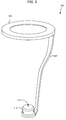
- FIG. 3 is a view of an integrated conductive flame holder 301, according to an embodiment.
- the integrated conductive flame holder 301 includes a conductive flame holding surface 102 and a conductive flame holder support 302 mechanically coupled to the conductive flame holding surface 102 and configured for mechanical coupling to another surface.
- the conductive flame holder support 302 can mechanically coupled to the fuel nozzle 110, as shown in FIG. 3 .
- the conductive flame holder 102 and the fuel nozzle 110 can be mechanically coupled to form an integrated fuel nozzle and conductive flame holder 301.
- the conductive flame holder 102, the flame holder support 302, and/or the fuel nozzle 110 can be joined by a variety of couplings. Various combinations of couplings can be combined.
- the conductive flame holder 102, the flame holder support 302, and/or the fuel nozzle 110 can be joined by threaded fasteners.
- the conductive flame holder 102, the flame holder support 302, and/or the fuel nozzle 110 can be joined by one or more rivets.
- the conductive flame holder 102, the flame holder support 302, and/or the fuel nozzle 110 can be joined by one or more weldments.
- the conductive flame holder 102, the flame holder support 302, and/or the fuel nozzle 110 can be joined by one or more brazed fittings.
- the conductive flame holder 102, the flame holder support 302, and/or the fuel nozzle 110 can be joined by one or more held-together surfaces.
- the conductive flame holder 102, the flame holder support 302, and/or the fuel nozzle 110 can be joined by one or more cold-formed joints.
- the conductive flame holder 102, the flame holder support 302, and/or the fuel nozzle 110 can be joined by one or more pressure-formed angles.
- the conductive flame holder 102, the flame holder support 302, and/or the fuel nozzle 110 can be joined by one or more co-molded interfaces.
- the conductive flame holder 102, the flame holder support 302, and/or the fuel nozzle 110 can be formed from or joined by one or more sintered shapes.
- the conductive flame holder 102, the flame holder support 302, and/or the fuel nozzle 110 can be joined by and one or more die-cast features. Additionally or alternatively, the conductive flame holder 102, the flame holder support 302, and the fuel nozzle 110 can be formed as a single piece.
- the fuel nozzle 110 can be conductive.
- the conductive flame holder 102, the flame holder support 302, and the fuel nozzle 110 can be aligned such that a fuel aperture 111 in the fuel nozzle 110 is aligned to cause the diverging fuel stream (not shown) to pass substantially along a common centerline through the fuel aperture 111 and the aperture formed by the conductive flame holder 102.
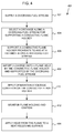
- FIG. 4 is a flow chart showing a method 401 for operating a low NOx burner, according to an embodiment.
- a diverging fuel stream is provided.
- a conductive flame holder is supported proximate a diverging fuel stream at a selected distance along the diverging fuel stream.
- a charge is imparted onto a flame held by the conductive flame holder and supported by the diverging fuel stream.
- flame holding and flame ignition are maintained responsive to the cooperation between the imparted charge on the flame and the conductive flame holder.
- heat from the flame is applied to a heat-receiving surface.
- applying heat to a heat-receiving surface can include providing heat in a furnace, in a boiler, in a gas turbine, or in a process material heater.
- the selected distance along the diverging fuel stream can, for example, substantially correspond to a flammability limit of the fuel.
- the method 401 includes step 404 wherein the selected distance is determined.
- determining the selected distance includes receiving a signal or operating a sensor to generate a signal indicative of a fuel condition, for example.
- the distance X along a stream of the fuel is calculated or looked up.
- the distance X has a relationship to a lean flammability limit corresponding to the fuel condition, for example.
- the distance X, data corresponding to the distance X, or a signal corresponding to the distance X is output.
- the output drives a conductive flame holder support to the distance X or an indication of the distance X can be output on an instrument for viewing by a user (e.g., an operating engineer) for manual adjustment of the distance X.
- the method 401 may optionally include driving an actuator to support the conductive flame holder at the selected distance along the diverging fuel stream (not shown).
- the method 401 also includes applying a voltage to the charge source.
- the charge source imparts the charge concentration responsive to the applied voltage.
- Applying a voltage to the charge source can optionally include applying a time-varying voltage to the charge source.
- Applying a voltage to the charge source can include applying a periodic voltage waveform having a 50 to 10,000 Hertz frequency.
- applying a voltage to the charge source can include applying a periodic voltage waveform having a 200 to 800 Hertz frequency.
- Applying a voltage to the charge source can include applying a square waveform, sine waveform, triangular waveform, truncated triangular waveform, sawtooth waveform, logarithmic waveform, or exponential waveform.
- Applying a voltage to the charge source can include applying a waveform having ⁇ 1000 volt to ⁇ 115,000 volt amplitude.
- applying a voltage to the charge source can include applying a waveform having ⁇ 8000 volt to ⁇ 40,000 volt amplitude.
- imparting a charge can include applying a voltage to a sharp electrode proximate to the flame.
- imparting a charge can include applying a voltage to a substantially dull electrode proximate to the flame.
- Imparting a charge can optionally include applying a voltage to a depletion electrode configured to deplete from the flame ions or electrons having a non-majority charge sign.
- imparting a charge can include applying a voltage to a charge adding apparatus configured to apply the majority charge to the flame.
- the method 401 includes step 410, wherein a voltage condition is applied to or maintained on the conductive flame holder, according to an embodiment.
- Applying or maintaining a voltage condition to the conductive flame holder includes applying a voltage different than a voltage applied to a charge source that imparts the charge onto the flame.
- applying or maintaining a voltage condition on the conductive flame holder can include applying a second time-varying voltage to the electrically conductive surface, the second time-varying voltage being opposite in sign to a time-varying charge imparted onto the flame.
- applying or maintaining a voltage condition on the conductive flame holder can include maintaining substantially voltage ground.
- applying or maintaining a voltage condition to the conductive flame holder can include maintaining electrical isolation from ground and from voltages other than the voltage corresponding to the charges imparted onto the flame.
- FIG. 5 is a diagram 501 illustrating a theory explaining the behavior of the methods and systems described in conjunction with FIGS. 1-4 , according to an illustrative embodiment.
- voltage, V is plotted as a function of time, t.
- the conductive flame holder 102 When the conductive flame holder 102 is allowed to float, its voltage can be described by a phase-shifted waveform 504, shown as a dashed line.
- the voltage 504 of the conductive flame holder 102 follows.
- the voltage 502 applied by the charge source 106 to the flame is lower than the voltage 504 responsively held by the conductive flame holder 102.
- electrons are attracted out of at least portions of the flame toward the conductive flame holder 102.
- positively charged species are attracted from proximity to the conductive flame holder 102 toward the flame.
- Current flow corresponding to flow of electrons toward the conductive flame holder 102 correspond (during the first half cycle 506) to the holding of the flame to the conductive flame holder 102.
- the voltage 502 applied by the charge source 106 to the flame is higher than the voltage 504 responsively held by the conductive flame holder 102.
- electrons are attracted from proximity to the conductive flame holder 102 and into the flame and positive species are attracted from the flame and into proximity with the conductive flame holder 102.
- Current flow corresponding to flow of positive ions toward the conductive flame holder 102 (or flow of electrons away from the conductive flame holder 102) corresponds (during the second half cycle 508) to the holding of the flame to the conductive flame holder 102.
- the movement of charged species to and from the conductive flame holder 102 acts to initiate the combustion reaction.
- the charged species tend to combine with fuel or oxygen to form reactive species that participate in the combustion reaction.
- the charge species tend to attract oppositely charged species from fuel or oxygen, with the remaining fuel or oxygen fragment being a reactive species that participates in the combustion reaction.
- a method of determining a distance X along a fuel stream for supporting a conductive flame holder may include receiving a signal or operating a sensor to generate a signal indicative of a fuel condition, calculating or looking up a distance X along a stream of the fuel, the distance X having a relationship to a lean flammability limit corresponding to the fuel condition, and outputting the distance X, data corresponding to the distance X, or a signal corresponding to the distance X to drive a conductive flame holder support to the distance X or outputting an indication of the distance X on an instrument for viewing by a user.
- a non-transitory computer readable media carries computer executable instructions configured to cause an electronic control module to perform a method including the steps of receiving a signal or operating a sensor to generate a signal indicative of a fuel condition, calculating or looking up a distance along a stream of the fuel, the distance having a relationship to a lean flammability limit corresponding to the fuel condition.
- the computer readable media can also carry computer executable instructions for outputting the distance, outputting data corresponding to the distance, or outputting a signal corresponding to the distance to drive a conductive flame holder support to the distance. Additionally or alternatively, the computer readable media can also carry computer executable instructions for outputting an indication of the distance on an instrument for viewing by a user.
Landscapes
- Engineering & Computer Science (AREA)
- Chemical & Material Sciences (AREA)
- Combustion & Propulsion (AREA)
- Mechanical Engineering (AREA)
- General Engineering & Computer Science (AREA)
- Gas Burners (AREA)
- Control Of Combustion (AREA)
Claims (15)
- Brûleur (101) à faible émission d'oxydes d'azote (NOx), comprenant :une buse (110) conçue pour produire un flux divergent de combustible (104) ;un stabilisateur de flamme conducteur (102) supporté à proximité de la buse (110), à une position le long du flux divergent de combustible correspondant à une valeur sélectionnée de concentration en combustible, concentration en oxygène, stoechiométrie combustible/oxygène, ou une combinaison de celles-ci ; etune source de charge (106) conçue pour communiquer une concentration de charge électrique sur une surface de flamme (108) maintenue par le stabilisateur de flamme conducteur (102), dans lequel la concentration de charge communiquée est sélectionnée pour faire en sorte que la flamme reste allumée et en contact avec le stabilisateur de flamme conducteur.
- Brûleur à faible émission de NOx selon la revendication 1, dans lequel la position correspond essentiellement à une limite pauvre d'inflammabilité du combustible dans le flux de combustible (104).
- Brûleur à faible émission de NOx selon la revendication 2, comprenant en outre :un support réglable (302) conçu pour changer la position à laquelle le stabilisateur de flamme conducteur (102) est supporté en réponse à un changement dans la limite pauvre d'inflammabilité ou un autre paramètre opérationnel ; etun module de commande électronique conçu pour entraîner le support réglable (302) pour sélectionner la position, correspondant essentiellement à la limite pauvre d'inflammabilité du combustible dans le flux de combustible (104), à laquelle le stabilisateur de flamme conducteur (102) est supporté.
- Brûleur à faible émission de NOx selon la revendication 1, dans lequel :le stabilisateur de flamme conducteur (102) inclut une pluralité de stabilisateurs de flamme conducteurs dimensionnés pour correspondre aux diamètres sélectionnés respectifs correspondant au flux divergent de combustible (104).
- Brûleur à faible émission de NOx selon la revendication 1, dans lequel le stabilisateur de flamme conducteur (102) inclut une électrode effilée.
- Brûleur à faible émission de NOx selon la revendication 1, dans lequel une condition de tension sélectionnée du stabilisateur de flamme conducteur (102) inclut une connexion de tension à la masse.
- Brûleur à faible émission de NOx selon la revendication 1, dans lequel une condition de tension sélectionnée du stabilisateur de flamme conducteur (102) inclut une isolation électrique par rapport à la masse et à des tensions autres que la tension correspondant aux charges communiquées sur la flamme.
- Brûleur à faible émission de NOx selon la revendication 1, comprenant en outre :une source de tension (116) conçue pour appliquer une tension à la source de charge (106) ;dans lequel la source de charge (106) est conçue pour communiquer la concentration de charge en réponse à la tension appliquée.
- Procédé d'exploitation d'un brûleur (101) à faible émission d'oxydes d'azote (NOx), dans lequel un stabilisateur de flamme conducteur (102) est supporté à proximité d'un flux divergent de combustible (104) à une position le long du flux divergent de combustible qui correspond essentiellement à une limite d'inflammabilité du combustible ; et
une charge électrique est communiquée sur une flamme qui est maintenue par le stabilisateur de flamme conducteur(102) et supportée par le flux divergent de combustible (104). - Procédé d'exploitation d'un brûleur à faible émission de NOx selon la revendication 9, comprenant en outre la sélection de la position, et dans lequel la détermination de la position sélectionnée comprend en outre :la réception d'un signal ou le fonctionnement d'un capteur pour produire un signal indicatif d'une condition de combustible ;le calcul ou la recherche de la position sélectionnée le long d'un flux du combustible, la position sélectionnée ayant une relation avec une limite pauvre d'inflammabilité correspondant à la condition de combustible ; etla sortie de données de position correspondant à la position sélectionnée ou d'un signal correspondant à la position sélectionnée pour entraîner un support stabilisateur de flamme conducteur (302) à la position sélectionnée ; etl'entraînement d'un actionneur pour supporter le stabilisateur de flamme conducteur (102) au niveau de la position sélectionnée le long du flux divergent de combustible (104).
- Procédé d'exploitation d'un brûleur à faible émission de NOx selon la revendication 9, comprenant :l'application au stabilisateur de flamme conducteur (102) d'une tension différente d'une tension appliquée à une source de charge (106) qui communique la charge électrique sur la flamme.
- Procédé d'exploitation d'un brûleur à faible émission de NOx selon la revendication 11, dans lequel l'application d'une condition de tension au stabilisateur de flamme conducteur (102) inclut l'application à une surface électroconductrice sur le stabilisateur de flamme (102) d'une tension périodique qui est de signe opposé à une charge électrique communiquée périodiquement sur la flamme.
- Procédé d'exploitation d'un brûleur à faible émission de NOx selon la revendication 11, dans lequel l'application d'une condition de tension au stabilisateur de flamme conducteur (102) inclut le maintien essentiel d'une masse de tension.
- Procédé d'exploitation d'un brûleur à faible émission de NOx selon la revendication 11, dans lequel l'application d'une condition de tension au stabilisateur de flamme conducteur (102) inclut le maintien d'une isolation électrique par rapport à la masse et à des tensions autres que la tension correspondant aux charges communiquées sur la flamme.
- Procédé d'exploitation d'un brûleur à faible émission de NOx selon la revendication 9, comprenant la sélection de la charge électrique communiquée en une quantité permettant de faire en sorte que la flamme reste allumée et en contact avec le stabilisateur de flamme conducteur (102).
Applications Claiming Priority (3)
| Application Number | Priority Date | Filing Date | Title |
|---|---|---|---|
| US201261653722P | 2012-05-31 | 2012-05-31 | |
| US201261669634P | 2012-07-09 | 2012-07-09 | |
| PCT/US2013/043658 WO2013181563A1 (fr) | 2012-05-31 | 2013-05-31 | Brûleur à faible taux d'émission de nox et procédé de fonctionnement d'un brûleur à faible taux d'émission en nox |
Publications (3)
| Publication Number | Publication Date |
|---|---|
| EP2856031A1 EP2856031A1 (fr) | 2015-04-08 |
| EP2856031A4 EP2856031A4 (fr) | 2016-02-17 |
| EP2856031B1 true EP2856031B1 (fr) | 2016-10-19 |
Family
ID=49670654
Family Applications (2)
| Application Number | Title | Priority Date | Filing Date |
|---|---|---|---|
| EP13796709.7A Not-in-force EP2856031B1 (fr) | 2012-05-31 | 2013-05-31 | Brûleur à faible taux d'émission de nox et procédé de fonctionnement d'un brûleur à faible taux d'émission en nox |
| EP13797552.0A Withdrawn EP2856032A4 (fr) | 2012-05-31 | 2013-05-31 | Brûleur à flamme suspendue, à faible taux d'émission de nox |
Family Applications After (1)
| Application Number | Title | Priority Date | Filing Date |
|---|---|---|---|
| EP13797552.0A Withdrawn EP2856032A4 (fr) | 2012-05-31 | 2013-05-31 | Brûleur à flamme suspendue, à faible taux d'émission de nox |
Country Status (4)
| Country | Link |
|---|---|
| US (5) | US20150118629A1 (fr) |
| EP (2) | EP2856031B1 (fr) |
| CN (2) | CN104334970A (fr) |
| WO (3) | WO2013181545A1 (fr) |
Families Citing this family (72)
| Publication number | Priority date | Publication date | Assignee | Title |
|---|---|---|---|---|
| US9732958B2 (en) | 2010-04-01 | 2017-08-15 | Clearsign Combustion Corporation | Electrodynamic control in a burner system |
| US11073280B2 (en) | 2010-04-01 | 2021-07-27 | Clearsign Technologies Corporation | Electrodynamic control in a burner system |
| CN104169725B (zh) | 2012-03-01 | 2018-04-17 | 克利尔赛恩燃烧公司 | 配置为与火焰电动交互的惰性电极和系统 |
| US9289780B2 (en) | 2012-03-27 | 2016-03-22 | Clearsign Combustion Corporation | Electrically-driven particulate agglomeration in a combustion system |
| US9371994B2 (en) | 2013-03-08 | 2016-06-21 | Clearsign Combustion Corporation | Method for Electrically-driven classification of combustion particles |
| US9696031B2 (en) | 2012-03-27 | 2017-07-04 | Clearsign Combustion Corporation | System and method for combustion of multiple fuels |
| EP2856031B1 (fr) | 2012-05-31 | 2016-10-19 | Clearsign Combustion Corporation | Brûleur à faible taux d'émission de nox et procédé de fonctionnement d'un brûleur à faible taux d'émission en nox |
| US9702550B2 (en) | 2012-07-24 | 2017-07-11 | Clearsign Combustion Corporation | Electrically stabilized burner |
| US9310077B2 (en) | 2012-07-31 | 2016-04-12 | Clearsign Combustion Corporation | Acoustic control of an electrodynamic combustion system |
| WO2014040075A1 (fr) | 2012-09-10 | 2014-03-13 | Clearsign Combustion Corporation | Commande de combustion électrodynamique par élément électrique à limitation de courant |
| US20140162198A1 (en) | 2012-11-27 | 2014-06-12 | Clearsign Combustion Corporation | Multistage ionizer for a combustion system |
| WO2014085720A1 (fr) | 2012-11-27 | 2014-06-05 | Clearsign Combustion Corporation | Bruleur à jets multiples doté d'interaction de charge |
| US9513006B2 (en) | 2012-11-27 | 2016-12-06 | Clearsign Combustion Corporation | Electrodynamic burner with a flame ionizer |
| US9562681B2 (en) | 2012-12-11 | 2017-02-07 | Clearsign Combustion Corporation | Burner having a cast dielectric electrode holder |
| US10677454B2 (en) | 2012-12-21 | 2020-06-09 | Clearsign Technologies Corporation | Electrical combustion control system including a complementary electrode pair |
| CN104838208A (zh) | 2012-12-26 | 2015-08-12 | 克利尔赛恩燃烧公司 | 带有栅切换电极的燃烧系统 |
| US9441834B2 (en) | 2012-12-28 | 2016-09-13 | Clearsign Combustion Corporation | Wirelessly powered electrodynamic combustion control system |
| US9469819B2 (en) | 2013-01-16 | 2016-10-18 | Clearsign Combustion Corporation | Gasifier configured to electrodynamically agitate charged chemical species in a reaction region and related methods |
| US10364984B2 (en) | 2013-01-30 | 2019-07-30 | Clearsign Combustion Corporation | Burner system including at least one coanda surface and electrodynamic control system, and related methods |
| US10125983B2 (en) | 2013-02-14 | 2018-11-13 | Clearsign Combustion Corporation | High output porous tile burner |
| CA2892229A1 (fr) * | 2013-02-14 | 2014-08-21 | Clearsign Combustion Corporation | Procede de demarrage et mecanisme destine a un bruleur possedant un stabilisateur de flamme perfore |
| US10386062B2 (en) | 2013-02-14 | 2019-08-20 | Clearsign Combustion Corporation | Method for operating a combustion system including a perforated flame holder |
| US11460188B2 (en) | 2013-02-14 | 2022-10-04 | Clearsign Technologies Corporation | Ultra low emissions firetube boiler burner |
| WO2015112950A1 (fr) | 2014-01-24 | 2015-07-30 | Clearsign Combustion Corporation | Chaudière à tubes de fumée à faible taux d'émission de nox |
| US10571124B2 (en) | 2013-02-14 | 2020-02-25 | Clearsign Combustion Corporation | Selectable dilution low NOx burner |
| US10119704B2 (en) | 2013-02-14 | 2018-11-06 | Clearsign Combustion Corporation | Burner system including a non-planar perforated flame holder |
| US10458649B2 (en) | 2013-02-14 | 2019-10-29 | Clearsign Combustion Corporation | Horizontally fired burner with a perforated flame holder |
| WO2014127306A1 (fr) | 2013-02-14 | 2014-08-21 | Clearsign Combustion Corporation | Brûleur à faible dégagement de nox à niveau de dilution sélectionnable |
| US9377189B2 (en) * | 2013-02-21 | 2016-06-28 | Clearsign Combustion Corporation | Methods for operating an oscillating combustor with pulsed charger |
| US9696034B2 (en) | 2013-03-04 | 2017-07-04 | Clearsign Combustion Corporation | Combustion system including one or more flame anchoring electrodes and related methods |
| US9664386B2 (en) | 2013-03-05 | 2017-05-30 | Clearsign Combustion Corporation | Dynamic flame control |
| US10190767B2 (en) | 2013-03-27 | 2019-01-29 | Clearsign Combustion Corporation | Electrically controlled combustion fluid flow |
| US9739479B2 (en) | 2013-03-28 | 2017-08-22 | Clearsign Combustion Corporation | Battery-powered high-voltage converter circuit with electrical isolation and mechanism for charging the battery |
| WO2014183135A1 (fr) | 2013-05-10 | 2014-11-13 | Clearsign Combustion Corporation | Système combustion et procédé de démarrage électriquement assisté |
| US9574767B2 (en) | 2013-07-29 | 2017-02-21 | Clearsign Combustion Corporation | Combustion-powered electrodynamic combustion system |
| WO2015017084A1 (fr) | 2013-07-30 | 2015-02-05 | Clearsign Combustion Corporation | Chambre de combustion pourvue d'un corps non métallique présentant des électrodes externes |
| WO2015038245A1 (fr) | 2013-09-13 | 2015-03-19 | Clearsign Combustion Corporation | Commande transitoire d'une réaction de combustion |
| WO2015042613A1 (fr) | 2013-09-23 | 2015-03-26 | Christopher A. Wiklof | Stabilisateur de flamme poreux pour combustion à faible émission de nox |
| EP3049721A4 (fr) | 2013-09-23 | 2017-09-20 | Clearsign Combustion Corporation | Système de brûleur utilisant de multiples stabilisateurs de flamme perforés et procédé de fonctionnement |
| WO2015042566A1 (fr) | 2013-09-23 | 2015-03-26 | Clearsign Combustion Corporation | Régulation de l'ampleur physique d'une réaction de combustion |
| WO2015051377A1 (fr) | 2013-10-04 | 2015-04-09 | Clearsign Combustion Corporation | Dispositif d'ionisation pour un système de combustion |
| EP3055616B1 (fr) | 2013-10-07 | 2020-12-09 | ClearSign Technologies Corporation | Brûleur à prémélangé à stabilisateur perforé |
| US20150104748A1 (en) | 2013-10-14 | 2015-04-16 | Clearsign Combustion Corporation | Electrodynamic combustion control (ecc) technology for biomass and coal systems |
| US10066835B2 (en) | 2013-11-08 | 2018-09-04 | Clearsign Combustion Corporation | Combustion system with flame location actuation |
| EP3090210A1 (fr) * | 2013-12-31 | 2016-11-09 | Clearsign Combustion Corporation | Procédé et appareil pour étendre les limites d'inflammabilité dans une réaction de combustion |
| WO2015123683A1 (fr) * | 2014-02-14 | 2015-08-20 | Clearsign Combustion Corporation | Application d'un champ électrique à une réaction de combustion soutenue par un porte-flamme perforé |
| CN106103338B (zh) | 2014-02-14 | 2018-04-20 | 克利尔赛恩燃烧公司 | 具有有孔火焰保持器的顶烧式燃烧器 |
| US10174938B2 (en) | 2014-06-30 | 2019-01-08 | Clearsign Combustion Corporation | Low inertia power supply for applying voltage to an electrode coupled to a flame |
| US10281140B2 (en) | 2014-07-15 | 2019-05-07 | Chevron U.S.A. Inc. | Low NOx combustion method and apparatus |
| US9885496B2 (en) | 2014-07-28 | 2018-02-06 | Clearsign Combustion Corporation | Fluid heater with perforated flame holder |
| US9791171B2 (en) | 2014-07-28 | 2017-10-17 | Clearsign Combustion Corporation | Fluid heater with a variable-output burner including a perforated flame holder and method of operation |
| WO2016018610A1 (fr) * | 2014-07-30 | 2016-02-04 | Clearsign Combustion Corporation | Ioniseur de flamme unipolaire asymétrique utilisant un transformateur-élévateur |
| US9828288B2 (en) | 2014-08-13 | 2017-11-28 | Clearsign Combustion Corporation | Perforated burner for a rotary kiln |
| US10458647B2 (en) | 2014-08-15 | 2019-10-29 | Clearsign Combustion Corporation | Adaptor for providing electrical combustion control to a burner |
| US9702547B2 (en) | 2014-10-15 | 2017-07-11 | Clearsign Combustion Corporation | Current gated electrode for applying an electric field to a flame |
| US20160138799A1 (en) * | 2014-11-13 | 2016-05-19 | Clearsign Combustion Corporation | Burner or boiler electrical discharge control |
| US10801723B2 (en) | 2015-02-17 | 2020-10-13 | Clearsign Technologies Corporation | Prefabricated integrated combustion assemblies and methods of installing the same into a combustion system |
| WO2016134061A1 (fr) | 2015-02-17 | 2016-08-25 | Clearsign Combustion Corporation | Stabilisateur de flamme perforé à buse de carburant réglable |
| US12247733B2 (en) | 2015-02-17 | 2025-03-11 | Clearsign Technologies Corporation | Prefabricated integrated combustion assemblies and methods of installing the same into a combustion system |
| WO2016133934A1 (fr) | 2015-02-17 | 2016-08-25 | Clearsign Combustion Corporation | Procédés d'amélioration d'un système de combustion classique pour inclure un stabilisateur de flamme perforé |
| US10006715B2 (en) | 2015-02-17 | 2018-06-26 | Clearsign Combustion Corporation | Tunnel burner including a perforated flame holder |
| US10088153B2 (en) | 2015-12-29 | 2018-10-02 | Clearsign Combustion Corporation | Radiant wall burner including perforated flame holders |
| US10551058B2 (en) | 2016-03-18 | 2020-02-04 | Clearsign Technologies Corporation | Multi-nozzle combustion assemblies including perforated flame holder, combustion systems including the combustion assemblies, and related methods |
| US10514165B2 (en) | 2016-07-29 | 2019-12-24 | Clearsign Combustion Corporation | Perforated flame holder and system including protection from abrasive or corrosive fuel |
| US10619845B2 (en) | 2016-08-18 | 2020-04-14 | Clearsign Combustion Corporation | Cooled ceramic electrode supports |
| US10539326B2 (en) | 2016-09-07 | 2020-01-21 | Clearsign Combustion Corporation | Duplex burner with velocity-compensated mesh and thickness |
| RU2694268C1 (ru) * | 2018-02-06 | 2019-07-11 | Федеральное государственное бюджетное образовательное учреждение высшего образования "Нижегородский государственный архитектурно-строительный университет" (ННГАСУ) | Способ интенсификации и управления пламенем |
| WO2019196045A1 (fr) * | 2018-04-12 | 2019-10-17 | 同济大学 | Procédé et système pour réduire la concentration en substances polluantes dans une fumée générée par combustion |
| HUE055228T2 (hu) * | 2018-12-06 | 2021-11-29 | Siemens Ag | Lángfigyelõ vezérlõrendszer |
| CN113606606B (zh) * | 2021-04-14 | 2022-12-06 | 中国航空发动机研究院 | 一种利用电场控制发动机的方法及发动机 |
| CN115076688A (zh) * | 2022-07-15 | 2022-09-20 | 王青芝 | 一种辅助火焰燃烧的装置 |
| CN117663168B (zh) * | 2023-12-06 | 2024-07-12 | 石家庄绿洁节能科技有限公司 | 碳核聚集燃烧装置 |
Family Cites Families (115)
| Publication number | Priority date | Publication date | Assignee | Title |
|---|---|---|---|---|
| US1153182A (en) | 1912-12-19 | 1915-09-07 | Frederic W C Schniewind | Purification of coal. |
| US2127977A (en) | 1935-09-07 | 1938-08-23 | Weston Electrical Instr Corp | Thermionic relay circuits |
| US2511177A (en) * | 1945-07-14 | 1950-06-13 | Republic Flow Meters Co | Apparatus for measuring the composition of a gas |
| US2604936A (en) | 1946-01-15 | 1952-07-29 | Metal Carbides Corp | Method and apparatus for controlling the generation and application of heat |
| US2942420A (en) | 1957-10-28 | 1960-06-28 | Gen Electric | Ignition mechanism |
| CH359724A (fr) | 1958-12-11 | 1962-01-31 | Commissariat Energie Atomique | Procédé et dispositif électriques pour améliorer les échanges thermiques entre un gaz et une surface d'échange |
| DE1121762B (de) | 1960-04-14 | 1962-01-11 | Alberto Wobig | Brenner fuer gasfoermige oder fluessige Brennstoffe |
| US3004137A (en) | 1960-06-07 | 1961-10-10 | Comb And Explosives Res Inc | Method and apparatus for the production of high gas temperatures |
| US3087472A (en) | 1961-03-30 | 1963-04-30 | Asakawa Yukichi | Method and apparatus for the improved combustion of fuels |
| GB1042014A (en) | 1961-11-10 | 1966-09-07 | Kenneth Payne | A fuel burner |
| US3224485A (en) | 1963-05-06 | 1965-12-21 | Inter Probe | Heat control device and method |
| US3301307A (en) | 1963-11-12 | 1967-01-31 | Ngk Insulators Ltd | Device for detecting the configuration of a burning flame |
| DE1254364B (de) | 1964-05-30 | 1967-11-16 | Cockerill Ougree Sa | Verfahren zur Erzeugung eines Gasgemisches mit hohem Waermeinhalt zum Schmelzen und/oder zum Frischen von Metallen und Brenner zur Durchfuehrung des Verfahrens |
| US3373306A (en) * | 1964-10-27 | 1968-03-12 | Northern Natural Gas Co | Method and apparatus for the control of ionization in a distributed electrical discharge |
| GB1140861A (en) | 1965-02-11 | 1969-01-22 | Felix Jiri Weinberg | Fuel burners |
| US3306338A (en) | 1965-11-01 | 1967-02-28 | Exxon Research Engineering Co | Apparatus for the application of insulated a.c. fields to flares |
| US3416870A (en) | 1965-11-01 | 1968-12-17 | Exxon Research Engineering Co | Apparatus for the application of an a.c. electrostatic field to combustion flames |
| DE1274781B (de) | 1965-11-01 | 1968-08-08 | Exxon Research Engineering Co | Verfahren und Vorrichtung zur Verbesserung des Verbrennungswirkungsgrades bei Brennern |
| US3358731A (en) | 1966-04-01 | 1967-12-19 | Mobil Oil Corp | Liquid fuel surface combustion process and apparatus |
| US3503348A (en) | 1968-08-30 | 1970-03-31 | Hagan Ind Inc | Incinerator |
| US3749545A (en) | 1971-11-24 | 1973-07-31 | Univ Ohio State | Apparatus and method for controlling liquid fuel sprays for combustion |
| US3841824A (en) | 1972-09-25 | 1974-10-15 | G Bethel | Combustion apparatus and process |
| US3869362A (en) | 1973-01-11 | 1975-03-04 | Ebara Mfg | Process for removing noxious gas pollutants from effluent gases by irradiation |
| CA1070622A (fr) | 1974-08-19 | 1980-01-29 | James J. Schwab | Methode et appareil d'epuration electrostatique de gaz |
| US4020388A (en) | 1974-09-23 | 1977-04-26 | Massachusetts Institute Of Technology | Discharge device |
| FR2290945A1 (fr) | 1974-11-12 | 1976-06-11 | Paillaud Pierre | Procede pour ameliorer le rendement energetique d'une reaction |
| DE2456163C2 (de) | 1974-11-28 | 1986-03-13 | Daimler-Benz Ag, 7000 Stuttgart | Brennkammer, insbesondere Kolbenarbeitsraum eines Motors |
| JPS5343143A (en) | 1976-09-30 | 1978-04-19 | Tokai Trw & Co | Ignition plug |
| US4111636A (en) | 1976-12-03 | 1978-09-05 | Lawrence P. Weinberger | Method and apparatus for reducing pollutant emissions while increasing efficiency of combustion |
| US4118202A (en) | 1977-10-17 | 1978-10-03 | Ball Corporation | Pre-primed fuel and method and apparatus for its manufacture |
| JPS5551918A (en) | 1978-10-13 | 1980-04-16 | Nissan Motor Co Ltd | Internal combustion engine |
| US4304096A (en) | 1979-05-11 | 1981-12-08 | The Regents Of The University Of Minnesota | Method for reducing particulates discharged by combustion means |
| US4260394A (en) | 1979-08-08 | 1981-04-07 | Advanced Energy Dynamics, Inc. | Process for reducing the sulfur content of coal |
| JPS5819609A (ja) | 1981-07-29 | 1983-02-04 | Miura Eng Internatl Kk | 燃料燃焼方法 |
| US4439980A (en) | 1981-11-16 | 1984-04-03 | The United States Of America As Represented By The Secretary Of The Navy | Electrohydrodynamic (EHD) control of fuel injection in gas turbines |
| JPS59115903A (ja) * | 1982-12-21 | 1984-07-04 | Toshiharu Yamashita | バ−ナに付設する燃焼装置 |
| US4649260A (en) | 1983-03-16 | 1987-03-10 | Coal-O-Matic Pvba | Lighter for stove, open hearth and similar |
| JPS60216111A (ja) | 1984-04-11 | 1985-10-29 | Osaka Gas Co Ltd | 燃焼式加熱装置 |
| AU557122B2 (en) | 1984-07-24 | 1986-12-04 | Kawasaki Steel Corp. | Coiling a thin strip |
| US4675029A (en) | 1984-11-21 | 1987-06-23 | Geoenergy International, Corp. | Apparatus and method for treating the emission products of a wood burning stove |
| FR2577304B1 (fr) | 1985-02-08 | 1989-12-01 | Electricite De France | Electrobruleur a gaz a apport d'energie electrique. |
| JPS61265404A (ja) | 1985-05-17 | 1986-11-25 | Osaka Gas Co Ltd | バ−ナ |
| SE460737B (sv) | 1986-05-12 | 1989-11-13 | Konstantin Mavroudis | Panna foer fasta braenslen, foersedd med anordningar foer tillfoersel av sekundaerluft |
| FR2647186B1 (fr) * | 1989-05-19 | 1991-08-23 | Electricite De France | Electrobruleur a gaz a apport d'energie et amorcage assiste |
| US4987839A (en) | 1990-05-14 | 1991-01-29 | Wahlco, Inc. | Removal of particulate matter from combustion gas streams |
| CA2017777C (fr) | 1990-05-29 | 1996-02-06 | Serge Leleu | Electrobruleur a gaz a apport d'energie electrique et amorcage assiste |
| US5244381A (en) * | 1992-04-02 | 1993-09-14 | Lennox Industries Inc. | NOx flame spreader for an inshot burner |
| US5515681A (en) | 1993-05-26 | 1996-05-14 | Simmonds Precision Engine Systems | Commonly housed electrostatic fuel atomizer and igniter apparatus for combustors |
| JPH0748136A (ja) | 1993-08-09 | 1995-02-21 | Furukawa Electric Co Ltd:The | 火炎検出装置とそれを用いた多孔質ガラス母材製造装置および方法 |
| US5498154A (en) * | 1994-04-22 | 1996-03-12 | Leland C. Scheu | Burner with over surface ignitor and high limit control |
| EP0712477A1 (fr) | 1994-06-15 | 1996-05-22 | Thermal Energy Systems, Incorporated | Appareil et procede de reduction des emissions de particules a partir des processus de combustion |
| NO180315C (no) | 1994-07-01 | 1997-03-26 | Torfinn Johnsen | Forbrenningskammer med utstyr for å effektivisere forbrenning og redusere skadelige stoffer i avgassen |
| US5641282A (en) * | 1995-02-28 | 1997-06-24 | Gas Research Institute | Advanced radiant gas burner and method utilizing flame support rod structure |
| DE19542918A1 (de) | 1995-11-17 | 1997-05-22 | Asea Brown Boveri | Vorrichtung zur Dämpfung thermoakustischer Druckschwingungen |
| US6247921B1 (en) | 1996-05-23 | 2001-06-19 | American Standard International Inc. | Apparatus for generating a spark |
| JP3054596B2 (ja) | 1996-10-28 | 2000-06-19 | 照夫 新井 | バーナー |
| JP3663824B2 (ja) * | 1997-04-21 | 2005-06-22 | 松下電器産業株式会社 | 燃焼装置 |
| JPH1183013A (ja) * | 1997-09-04 | 1999-03-26 | Matsushita Electric Ind Co Ltd | 燃焼装置 |
| JP2001021110A (ja) * | 1999-07-06 | 2001-01-26 | Tokyo Gas Co Ltd | ガスバーナの燃焼方法及び装置 |
| JP2001056120A (ja) * | 1999-08-18 | 2001-02-27 | Matsushita Electric Ind Co Ltd | ガスコンロ |
| US7435082B2 (en) | 2000-02-11 | 2008-10-14 | Michael E. Jayne | Furnace using plasma ignition system for hydrocarbon combustion |
| DE60122414T2 (de) | 2000-04-01 | 2006-12-21 | Alstom Technology Ltd. | Verbrennungssystem für eine Gasturbine |
| US6453660B1 (en) | 2001-01-18 | 2002-09-24 | General Electric Company | Combustor mixer having plasma generating nozzle |
| IL144109A0 (en) * | 2001-07-02 | 2004-02-08 | Israel State | Method and apparatus for generating superheated steam |
| DE10137683C2 (de) * | 2001-08-01 | 2003-05-28 | Siemens Ag | Verfahren und Vorrichtung zur Beeinflussung von Verbrennungsvorgängen bei Brennstoffen |
| US20030051990A1 (en) | 2001-08-15 | 2003-03-20 | Crt Holdings, Inc. | System, method, and apparatus for an intense ultraviolet radiation source |
| US6742340B2 (en) | 2002-01-29 | 2004-06-01 | Affordable Turbine Power Company, Inc. | Fuel injection control system for a turbine engine |
| ES2272962T3 (es) | 2002-03-22 | 2007-05-01 | Pyroplasma Kg | Dispositivo para la combustion de combustibles. |
| US6736133B2 (en) | 2002-04-09 | 2004-05-18 | Hon Technology Inc. | Air filtration and sterilization system for a fireplace |
| US7159646B2 (en) | 2002-04-15 | 2007-01-09 | University Of Maryland | Electrohydrodynamically (EHD) enhanced heat transfer system and method with an encapsulated electrode |
| EP1411573A2 (fr) * | 2002-10-16 | 2004-04-21 | Matsushita Electric Industrial Co., Ltd. | Brûleur, générateur d'hydrogène et système de génération électrique à pile à combustible |
| US6640549B1 (en) | 2002-12-03 | 2003-11-04 | The United States Of America As Represented By The Secretary Of The Navy | Method and device for modulation of a flame |
| DE10260709B3 (de) * | 2002-12-23 | 2004-08-12 | Siemens Ag | Verfahren und Vorrichtung zur Beeinflussung von Verbrennungsvorgängen bei Brennstoffen |
| US7416137B2 (en) | 2003-01-22 | 2008-08-26 | Vast Power Systems, Inc. | Thermodynamic cycles using thermal diluent |
| US7243496B2 (en) | 2004-01-29 | 2007-07-17 | Siemens Power Generation, Inc. | Electric flame control using corona discharge enhancement |
| US7377114B1 (en) | 2004-06-02 | 2008-05-27 | Kevin P Pearce | Turbine engine pulsed fuel injection utilizing stagger injector operation |
| US6918755B1 (en) | 2004-07-20 | 2005-07-19 | Arvin Technologies, Inc. | Fuel-fired burner with skewed electrode arrangement |
| US7226496B2 (en) | 2004-11-30 | 2007-06-05 | Ranco Incorporated Of Delaware | Spot ventilators and method for spot ventilating bathrooms, kitchens and closets |
| US7226497B2 (en) | 2004-11-30 | 2007-06-05 | Ranco Incorporated Of Delaware | Fanless building ventilator |
| US7182805B2 (en) | 2004-11-30 | 2007-02-27 | Ranco Incorporated Of Delaware | Corona-discharge air mover and purifier for packaged terminal and room air conditioners |
| DE102004061300B3 (de) | 2004-12-20 | 2006-07-13 | Siemens Ag | Verfahren und Vorrichtung zur Beeinflussung von Verbrennungsvorgängen |
| CN2781708Y (zh) * | 2005-04-28 | 2006-05-17 | 宜兴市亿光电子有限公司 | 电子蜡烛灯 |
| CN2932035Y (zh) * | 2006-08-08 | 2007-08-08 | 深圳市宝安区松岗拓实制品厂 | 充电蜡烛 |
| CN101351638B (zh) | 2006-09-20 | 2012-09-26 | 创想科学技术工程株式会社 | 点火装置、内燃机、点火塞、等离子设备、废气降解装置、臭氧发生/消毒/杀菌装置,以及除臭装置 |
| US8082725B2 (en) | 2007-04-12 | 2011-12-27 | General Electric Company | Electro-dynamic swirler, combustion apparatus and methods using the same |
| US9347331B2 (en) | 2007-06-11 | 2016-05-24 | University Of Florida Research Foundation, Inc. | Electrodynamic control of blade clearance leakage loss in turbomachinery applications |
| US8245951B2 (en) | 2008-04-22 | 2012-08-21 | Applied Nanotech Holdings, Inc. | Electrostatic atomizing fuel injector using carbon nanotubes |
| US8851882B2 (en) | 2009-04-03 | 2014-10-07 | Clearsign Combustion Corporation | System and apparatus for applying an electric field to a combustion volume |
| JP2011069268A (ja) | 2009-09-25 | 2011-04-07 | Ngk Insulators Ltd | 排気ガス処理装置 |
| JP5075900B2 (ja) * | 2009-09-30 | 2012-11-21 | 株式会社日立製作所 | 水素含有燃料対応燃焼器および、その低NOx運転方法 |
| KR20120129907A (ko) | 2010-01-13 | 2012-11-28 | 클리어사인 컨버스천 코포레이션 | 열 전달의 전기적 제어 방법 및 장치 |
| DK2466204T3 (da) | 2010-12-16 | 2014-01-13 | Siemens Ag | Reguleringsindretning til et brænderanlæg |
| EP2673077A4 (fr) | 2011-02-09 | 2016-07-27 | Clearsign Comb Corp | Procédé et appareil pour entraîner de façon électrodynamique un gaz chargé ou des particules chargées entraînées dans un gaz |
| EP2495496B1 (fr) | 2011-03-03 | 2015-04-29 | Siemens Aktiengesellschaft | Installation de brûleur |
| US9284886B2 (en) | 2011-12-30 | 2016-03-15 | Clearsign Combustion Corporation | Gas turbine with Coulombic thermal protection |
| US20140208758A1 (en) | 2011-12-30 | 2014-07-31 | Clearsign Combustion Corporation | Gas turbine with extended turbine blade stream adhesion |
| US20160123576A1 (en) | 2011-12-30 | 2016-05-05 | Clearsign Combustion Corporation | Method and apparatus for enhancing flame radiation in a coal-burner retrofit |
| MX2014007905A (es) | 2011-12-30 | 2015-04-16 | Clearsign Comb Corp | Metodo y aparato para la mejora de la radiacion de la llama. |
| CA2862808A1 (fr) | 2012-02-22 | 2013-08-29 | Clearsign Combustion Corporation | Electrode refroidie et systeme de bruleur comprenant une electrode refroidie |
| US9377195B2 (en) | 2012-03-01 | 2016-06-28 | Clearsign Combustion Corporation | Inertial electrode and system configured for electrodynamic interaction with a voltage-biased flame |
| CN104169725B (zh) | 2012-03-01 | 2018-04-17 | 克利尔赛恩燃烧公司 | 配置为与火焰电动交互的惰性电极和系统 |
| US9696031B2 (en) | 2012-03-27 | 2017-07-04 | Clearsign Combustion Corporation | System and method for combustion of multiple fuels |
| WO2013147956A1 (fr) | 2012-03-27 | 2013-10-03 | Clearsign Combustion Corporation | Système et procédé de combustion de combustible multiple |
| US9289780B2 (en) | 2012-03-27 | 2016-03-22 | Clearsign Combustion Corporation | Electrically-driven particulate agglomeration in a combustion system |
| US9366427B2 (en) | 2012-03-27 | 2016-06-14 | Clearsign Combustion Corporation | Solid fuel burner with electrodynamic homogenization |
| WO2013166060A1 (fr) | 2012-04-30 | 2013-11-07 | Clearsign Combustion Corporation | Chambre de combustion à vitesse élevée |
| US20130291552A1 (en) | 2012-05-03 | 2013-11-07 | United Technologies Corporation | Electrical control of combustion |
| EP2856031B1 (fr) * | 2012-05-31 | 2016-10-19 | Clearsign Combustion Corporation | Brûleur à faible taux d'émission de nox et procédé de fonctionnement d'un brûleur à faible taux d'émission en nox |
| US20130323661A1 (en) | 2012-06-01 | 2013-12-05 | Clearsign Combustion Corporation | Long flame process heater |
| US20130336352A1 (en) | 2012-06-15 | 2013-12-19 | Clearsign Combustion Corporation | Electrically stabilized down-fired flame reactor |
| US20130333279A1 (en) | 2012-06-19 | 2013-12-19 | Clearsign Combustion Corporation | Flame enhancement for a rotary kiln |
| WO2014005143A1 (fr) | 2012-06-29 | 2014-01-03 | Clearsign Combustion Corporation | Système de combustion comprenant une électrode à effet corona |
| EP2738460A1 (fr) | 2012-11-29 | 2014-06-04 | Siemens Aktiengesellschaft | Système de combustion d'un moteur d'écoulement |
| US20140227646A1 (en) * | 2013-02-13 | 2014-08-14 | Clearsign Combustion Corporation | Combustion system including at least one fuel flow equalizer |
| US20150226424A1 (en) * | 2013-12-14 | 2015-08-13 | Clearsign Combustion Corporation | Method and apparatus for shaping a flame |
-
2013
- 2013-05-31 EP EP13796709.7A patent/EP2856031B1/fr not_active Not-in-force
- 2013-05-31 WO PCT/US2013/043635 patent/WO2013181545A1/fr not_active Ceased
- 2013-05-31 WO PCT/US2013/043668 patent/WO2013181569A2/fr not_active Ceased
- 2013-05-31 CN CN201380026628.2A patent/CN104334970A/zh active Pending
- 2013-05-31 US US14/404,171 patent/US20150118629A1/en not_active Abandoned
- 2013-05-31 WO PCT/US2013/043658 patent/WO2013181563A1/fr not_active Ceased
- 2013-05-31 CN CN201380026121.7A patent/CN104350332B/zh not_active Expired - Fee Related
- 2013-05-31 EP EP13797552.0A patent/EP2856032A4/fr not_active Withdrawn
- 2013-05-31 US US13/907,825 patent/US9453640B2/en not_active Expired - Fee Related
-
2014
- 2014-12-01 US US14/556,495 patent/US9909757B2/en not_active Expired - Fee Related
- 2014-12-01 US US14/556,655 patent/US20150147705A1/en not_active Abandoned
-
2017
- 2017-11-20 US US15/818,526 patent/US10753605B2/en not_active Expired - Fee Related
Non-Patent Citations (1)
| Title |
|---|
| None * |
Also Published As
| Publication number | Publication date |
|---|---|
| WO2013181563A1 (fr) | 2013-12-05 |
| US20150118629A1 (en) | 2015-04-30 |
| US9453640B2 (en) | 2016-09-27 |
| US20150147705A1 (en) | 2015-05-28 |
| US20150140498A1 (en) | 2015-05-21 |
| WO2013181545A1 (fr) | 2013-12-05 |
| CN104350332A (zh) | 2015-02-11 |
| US9909757B2 (en) | 2018-03-06 |
| EP2856031A1 (fr) | 2015-04-08 |
| US20180073727A1 (en) | 2018-03-15 |
| EP2856031A4 (fr) | 2016-02-17 |
| CN104350332B (zh) | 2016-11-09 |
| CN104395673A (zh) | 2015-03-04 |
| EP2856032A4 (fr) | 2016-02-10 |
| EP2856032A1 (fr) | 2015-04-08 |
| CN104334970A (zh) | 2015-02-04 |
| WO2013181569A3 (fr) | 2014-01-30 |
| US20130323655A1 (en) | 2013-12-05 |
| US10753605B2 (en) | 2020-08-25 |
| WO2013181569A2 (fr) | 2013-12-05 |
Similar Documents
| Publication | Publication Date | Title |
|---|---|---|
| EP2856031B1 (fr) | Brûleur à faible taux d'émission de nox et procédé de fonctionnement d'un brûleur à faible taux d'émission en nox | |
| US9209654B2 (en) | Method and apparatus for enhancing flame radiation | |
| US20160123576A1 (en) | Method and apparatus for enhancing flame radiation in a coal-burner retrofit | |
| CN103492805B (zh) | 用于扁平化火焰的系统和方法 | |
| US9702550B2 (en) | Electrically stabilized burner | |
| US20140287368A1 (en) | Premixed flame location control | |
| US20190113224A1 (en) | Method for electrically controlled combustion fluid flow | |
| US20150079524A1 (en) | LIFTED FLAME LOW NOx BURNER WITH FLAME POSITION CONTROL | |
| WO2013166084A1 (fr) | Turbine à gaz et dispositif de post-combustion de turbine à gaz | |
| Kim et al. | Effects of applying non-thermal plasma on combustion stability and emissions of NOx and CO in a model gas turbine combustor | |
| CN102162644A (zh) | 介质阻挡放电等离子体旋流装置 | |
| Pham et al. | Stabilization of a premixed methane–air flame using nanosecond repetitively pulsed discharges | |
| JP2013122215A (ja) | 着火装置、及び着火方法 | |
| Moeck et al. | Stabilization of a methane-air swirl flame by rotating nanosecond spark discharges | |
| CN105423296B (zh) | 一种燃烧器出口扩张段及采用其的燃烧器 | |
| JP2019184179A (ja) | 燃料の燃焼装置 | |
| US20160161111A1 (en) | Flow control of combustible mixture into combustion chamber | |
| US11754010B2 (en) | Combustion apparatus that combusts fuel | |
| US20240175578A1 (en) | Systems and methods for flame stabilization and heat-release modulation | |
| CN104566378B (zh) | 基于电弧放电等离子体的燃烧器喷嘴 | |
| CN104395673B (zh) | 低NOx燃烧器和操作低NOx燃烧器的方法 | |
| Choi et al. | Stabilization of a combustion process near lean blow off by an electric discharge | |
| CA2778722A1 (fr) | Regulation de debit d'un melange combustible dans une chambre de combustion | |
| RU2685462C1 (ru) | Способ факельного сжигания топлива | |
| KR20240130404A (ko) | 고전압 인가형 연소기 |
Legal Events
| Date | Code | Title | Description |
|---|---|---|---|
| PUAI | Public reference made under article 153(3) epc to a published international application that has entered the european phase |
Free format text: ORIGINAL CODE: 0009012 |
|
| 17P | Request for examination filed |
Effective date: 20141112 |
|
| AK | Designated contracting states |
Kind code of ref document: A1 Designated state(s): AL AT BE BG CH CY CZ DE DK EE ES FI FR GB GR HR HU IE IS IT LI LT LU LV MC MK MT NL NO PL PT RO RS SE SI SK SM TR |
|
| AX | Request for extension of the european patent |
Extension state: BA ME |
|
| DAX | Request for extension of the european patent (deleted) | ||
| RA4 | Supplementary search report drawn up and despatched (corrected) |
Effective date: 20160118 |
|
| RIC1 | Information provided on ipc code assigned before grant |
Ipc: F23N 5/12 20060101AFI20160112BHEP Ipc: F23D 99/00 20100101ALI20160112BHEP Ipc: F23D 14/42 20060101ALI20160112BHEP |
|
| REG | Reference to a national code |
Ref country code: DE Ref legal event code: R079 Ref document number: 602013013063 Country of ref document: DE Free format text: PREVIOUS MAIN CLASS: F23N0005120000 Ipc: F23C0099000000 |
|
| GRAP | Despatch of communication of intention to grant a patent |
Free format text: ORIGINAL CODE: EPIDOSNIGR1 |
|
| RIC1 | Information provided on ipc code assigned before grant |
Ipc: F23D 14/02 20060101ALI20160701BHEP Ipc: F23C 99/00 20060101AFI20160701BHEP Ipc: F23D 11/40 20060101ALI20160701BHEP Ipc: F23D 14/82 20060101ALI20160701BHEP |
|
| INTG | Intention to grant announced |
Effective date: 20160721 |
|
| GRAS | Grant fee paid |
Free format text: ORIGINAL CODE: EPIDOSNIGR3 |
|
| GRAA | (expected) grant |
Free format text: ORIGINAL CODE: 0009210 |
|
| AK | Designated contracting states |
Kind code of ref document: B1 Designated state(s): AL AT BE BG CH CY CZ DE DK EE ES FI FR GB GR HR HU IE IS IT LI LT LU LV MC MK MT NL NO PL PT RO RS SE SI SK SM TR |
|
| REG | Reference to a national code |
Ref country code: GB Ref legal event code: FG4D |
|
| REG | Reference to a national code |
Ref country code: CH Ref legal event code: EP |
|
| REG | Reference to a national code |
Ref country code: AT Ref legal event code: REF Ref document number: 838687 Country of ref document: AT Kind code of ref document: T Effective date: 20161115 |
|
| REG | Reference to a national code |
Ref country code: IE Ref legal event code: FG4D |
|
| REG | Reference to a national code |
Ref country code: DE Ref legal event code: R096 Ref document number: 602013013063 Country of ref document: DE |
|
| REG | Reference to a national code |
Ref country code: NL Ref legal event code: MP Effective date: 20161019 |
|
| REG | Reference to a national code |
Ref country code: LT Ref legal event code: MG4D |
|
| PG25 | Lapsed in a contracting state [announced via postgrant information from national office to epo] |
Ref country code: LV Free format text: LAPSE BECAUSE OF FAILURE TO SUBMIT A TRANSLATION OF THE DESCRIPTION OR TO PAY THE FEE WITHIN THE PRESCRIBED TIME-LIMIT Effective date: 20161019 |
|
| REG | Reference to a national code |
Ref country code: AT Ref legal event code: MK05 Ref document number: 838687 Country of ref document: AT Kind code of ref document: T Effective date: 20161019 |
|
| PG25 | Lapsed in a contracting state [announced via postgrant information from national office to epo] |
Ref country code: SE Free format text: LAPSE BECAUSE OF FAILURE TO SUBMIT A TRANSLATION OF THE DESCRIPTION OR TO PAY THE FEE WITHIN THE PRESCRIBED TIME-LIMIT Effective date: 20161019 Ref country code: GR Free format text: LAPSE BECAUSE OF FAILURE TO SUBMIT A TRANSLATION OF THE DESCRIPTION OR TO PAY THE FEE WITHIN THE PRESCRIBED TIME-LIMIT Effective date: 20170120 Ref country code: LT Free format text: LAPSE BECAUSE OF FAILURE TO SUBMIT A TRANSLATION OF THE DESCRIPTION OR TO PAY THE FEE WITHIN THE PRESCRIBED TIME-LIMIT Effective date: 20161019 Ref country code: NO Free format text: LAPSE BECAUSE OF FAILURE TO SUBMIT A TRANSLATION OF THE DESCRIPTION OR TO PAY THE FEE WITHIN THE PRESCRIBED TIME-LIMIT Effective date: 20170119 |
|
| PG25 | Lapsed in a contracting state [announced via postgrant information from national office to epo] |
Ref country code: IS Free format text: LAPSE BECAUSE OF FAILURE TO SUBMIT A TRANSLATION OF THE DESCRIPTION OR TO PAY THE FEE WITHIN THE PRESCRIBED TIME-LIMIT Effective date: 20170219 Ref country code: NL Free format text: LAPSE BECAUSE OF FAILURE TO SUBMIT A TRANSLATION OF THE DESCRIPTION OR TO PAY THE FEE WITHIN THE PRESCRIBED TIME-LIMIT Effective date: 20161019 Ref country code: ES Free format text: LAPSE BECAUSE OF FAILURE TO SUBMIT A TRANSLATION OF THE DESCRIPTION OR TO PAY THE FEE WITHIN THE PRESCRIBED TIME-LIMIT Effective date: 20161019 Ref country code: FI Free format text: LAPSE BECAUSE OF FAILURE TO SUBMIT A TRANSLATION OF THE DESCRIPTION OR TO PAY THE FEE WITHIN THE PRESCRIBED TIME-LIMIT Effective date: 20161019 Ref country code: PT Free format text: LAPSE BECAUSE OF FAILURE TO SUBMIT A TRANSLATION OF THE DESCRIPTION OR TO PAY THE FEE WITHIN THE PRESCRIBED TIME-LIMIT Effective date: 20170220 Ref country code: HR Free format text: LAPSE BECAUSE OF FAILURE TO SUBMIT A TRANSLATION OF THE DESCRIPTION OR TO PAY THE FEE WITHIN THE PRESCRIBED TIME-LIMIT Effective date: 20161019 Ref country code: BE Free format text: LAPSE BECAUSE OF FAILURE TO SUBMIT A TRANSLATION OF THE DESCRIPTION OR TO PAY THE FEE WITHIN THE PRESCRIBED TIME-LIMIT Effective date: 20161019 Ref country code: AT Free format text: LAPSE BECAUSE OF FAILURE TO SUBMIT A TRANSLATION OF THE DESCRIPTION OR TO PAY THE FEE WITHIN THE PRESCRIBED TIME-LIMIT Effective date: 20161019 Ref country code: RS Free format text: LAPSE BECAUSE OF FAILURE TO SUBMIT A TRANSLATION OF THE DESCRIPTION OR TO PAY THE FEE WITHIN THE PRESCRIBED TIME-LIMIT Effective date: 20161019 Ref country code: PL Free format text: LAPSE BECAUSE OF FAILURE TO SUBMIT A TRANSLATION OF THE DESCRIPTION OR TO PAY THE FEE WITHIN THE PRESCRIBED TIME-LIMIT Effective date: 20161019 |
|
| REG | Reference to a national code |
Ref country code: DE Ref legal event code: R097 Ref document number: 602013013063 Country of ref document: DE |
|
| PG25 | Lapsed in a contracting state [announced via postgrant information from national office to epo] |
Ref country code: DK Free format text: LAPSE BECAUSE OF FAILURE TO SUBMIT A TRANSLATION OF THE DESCRIPTION OR TO PAY THE FEE WITHIN THE PRESCRIBED TIME-LIMIT Effective date: 20161019 Ref country code: CZ Free format text: LAPSE BECAUSE OF FAILURE TO SUBMIT A TRANSLATION OF THE DESCRIPTION OR TO PAY THE FEE WITHIN THE PRESCRIBED TIME-LIMIT Effective date: 20161019 Ref country code: RO Free format text: LAPSE BECAUSE OF FAILURE TO SUBMIT A TRANSLATION OF THE DESCRIPTION OR TO PAY THE FEE WITHIN THE PRESCRIBED TIME-LIMIT Effective date: 20161019 Ref country code: EE Free format text: LAPSE BECAUSE OF FAILURE TO SUBMIT A TRANSLATION OF THE DESCRIPTION OR TO PAY THE FEE WITHIN THE PRESCRIBED TIME-LIMIT Effective date: 20161019 Ref country code: SK Free format text: LAPSE BECAUSE OF FAILURE TO SUBMIT A TRANSLATION OF THE DESCRIPTION OR TO PAY THE FEE WITHIN THE PRESCRIBED TIME-LIMIT Effective date: 20161019 |
|
| PLBE | No opposition filed within time limit |
Free format text: ORIGINAL CODE: 0009261 |
|
| STAA | Information on the status of an ep patent application or granted ep patent |
Free format text: STATUS: NO OPPOSITION FILED WITHIN TIME LIMIT |
|
| PG25 | Lapsed in a contracting state [announced via postgrant information from national office to epo] |
Ref country code: SM Free format text: LAPSE BECAUSE OF FAILURE TO SUBMIT A TRANSLATION OF THE DESCRIPTION OR TO PAY THE FEE WITHIN THE PRESCRIBED TIME-LIMIT Effective date: 20161019 Ref country code: LU Free format text: LAPSE BECAUSE OF NON-PAYMENT OF DUE FEES Effective date: 20170531 Ref country code: BG Free format text: LAPSE BECAUSE OF FAILURE TO SUBMIT A TRANSLATION OF THE DESCRIPTION OR TO PAY THE FEE WITHIN THE PRESCRIBED TIME-LIMIT Effective date: 20170119 Ref country code: IT Free format text: LAPSE BECAUSE OF FAILURE TO SUBMIT A TRANSLATION OF THE DESCRIPTION OR TO PAY THE FEE WITHIN THE PRESCRIBED TIME-LIMIT Effective date: 20161019 |
|
| 26N | No opposition filed |
Effective date: 20170720 |
|
| PG25 | Lapsed in a contracting state [announced via postgrant information from national office to epo] |
Ref country code: SI Free format text: LAPSE BECAUSE OF FAILURE TO SUBMIT A TRANSLATION OF THE DESCRIPTION OR TO PAY THE FEE WITHIN THE PRESCRIBED TIME-LIMIT Effective date: 20161019 |
|
| REG | Reference to a national code |
Ref country code: CH Ref legal event code: PL |
|
| GBPC | Gb: european patent ceased through non-payment of renewal fee |
Effective date: 20170531 |
|
| PG25 | Lapsed in a contracting state [announced via postgrant information from national office to epo] |
Ref country code: MC Free format text: LAPSE BECAUSE OF FAILURE TO SUBMIT A TRANSLATION OF THE DESCRIPTION OR TO PAY THE FEE WITHIN THE PRESCRIBED TIME-LIMIT Effective date: 20161019 |
|
| REG | Reference to a national code |
Ref country code: IE Ref legal event code: MM4A |
|
| PG25 | Lapsed in a contracting state [announced via postgrant information from national office to epo] |
Ref country code: CH Free format text: LAPSE BECAUSE OF NON-PAYMENT OF DUE FEES Effective date: 20170531 Ref country code: LI Free format text: LAPSE BECAUSE OF NON-PAYMENT OF DUE FEES Effective date: 20170531 |
|
| REG | Reference to a national code |
Ref country code: FR Ref legal event code: ST Effective date: 20180131 |
|
| PG25 | Lapsed in a contracting state [announced via postgrant information from national office to epo] |
Ref country code: GB Free format text: LAPSE BECAUSE OF NON-PAYMENT OF DUE FEES Effective date: 20170531 Ref country code: IE Free format text: LAPSE BECAUSE OF NON-PAYMENT OF DUE FEES Effective date: 20170531 |
|
| PG25 | Lapsed in a contracting state [announced via postgrant information from national office to epo] |
Ref country code: FR Free format text: LAPSE BECAUSE OF NON-PAYMENT OF DUE FEES Effective date: 20170531 |
|
| PG25 | Lapsed in a contracting state [announced via postgrant information from national office to epo] |
Ref country code: MT Free format text: LAPSE BECAUSE OF NON-PAYMENT OF DUE FEES Effective date: 20170531 |
|
| PG25 | Lapsed in a contracting state [announced via postgrant information from national office to epo] |
Ref country code: HU Free format text: LAPSE BECAUSE OF FAILURE TO SUBMIT A TRANSLATION OF THE DESCRIPTION OR TO PAY THE FEE WITHIN THE PRESCRIBED TIME-LIMIT; INVALID AB INITIO Effective date: 20130531 |
|
| PG25 | Lapsed in a contracting state [announced via postgrant information from national office to epo] |
Ref country code: CY Free format text: LAPSE BECAUSE OF FAILURE TO SUBMIT A TRANSLATION OF THE DESCRIPTION OR TO PAY THE FEE WITHIN THE PRESCRIBED TIME-LIMIT Effective date: 20161019 |
|
| PG25 | Lapsed in a contracting state [announced via postgrant information from national office to epo] |
Ref country code: MK Free format text: LAPSE BECAUSE OF FAILURE TO SUBMIT A TRANSLATION OF THE DESCRIPTION OR TO PAY THE FEE WITHIN THE PRESCRIBED TIME-LIMIT Effective date: 20161019 |
|
| PG25 | Lapsed in a contracting state [announced via postgrant information from national office to epo] |
Ref country code: TR Free format text: LAPSE BECAUSE OF FAILURE TO SUBMIT A TRANSLATION OF THE DESCRIPTION OR TO PAY THE FEE WITHIN THE PRESCRIBED TIME-LIMIT Effective date: 20161019 |
|
| PG25 | Lapsed in a contracting state [announced via postgrant information from national office to epo] |
Ref country code: AL Free format text: LAPSE BECAUSE OF FAILURE TO SUBMIT A TRANSLATION OF THE DESCRIPTION OR TO PAY THE FEE WITHIN THE PRESCRIBED TIME-LIMIT Effective date: 20161019 |
|
| PGFP | Annual fee paid to national office [announced via postgrant information from national office to epo] |
Ref country code: DE Payment date: 20200523 Year of fee payment: 8 |
|
| REG | Reference to a national code |
Ref country code: DE Ref legal event code: R119 Ref document number: 602013013063 Country of ref document: DE |
|
| PG25 | Lapsed in a contracting state [announced via postgrant information from national office to epo] |
Ref country code: DE Free format text: LAPSE BECAUSE OF NON-PAYMENT OF DUE FEES Effective date: 20211201 |