EP2856502B1 - Substrat de boîtier de semi-conducteurs et son procédé de fabrication - Google Patents
Substrat de boîtier de semi-conducteurs et son procédé de fabrication Download PDFInfo
- Publication number
- EP2856502B1 EP2856502B1 EP13793826.2A EP13793826A EP2856502B1 EP 2856502 B1 EP2856502 B1 EP 2856502B1 EP 13793826 A EP13793826 A EP 13793826A EP 2856502 B1 EP2856502 B1 EP 2856502B1
- Authority
- EP
- European Patent Office
- Prior art keywords
- pad
- insulating substrate
- circuit pattern
- solder resist
- substrate
- Prior art date
- Legal status (The legal status is an assumption and is not a legal conclusion. Google has not performed a legal analysis and makes no representation as to the accuracy of the status listed.)
- Active
Links
Images


Classifications
-
- H—ELECTRICITY
- H10—SEMICONDUCTOR DEVICES; ELECTRIC SOLID-STATE DEVICES NOT OTHERWISE PROVIDED FOR
- H10W—GENERIC PACKAGES, INTERCONNECTIONS, CONNECTORS OR OTHER CONSTRUCTIONAL DETAILS OF DEVICES COVERED BY CLASS H10
- H10W70/00—Package substrates; Interposers; Redistribution layers [RDL]
- H10W70/60—Insulating or insulated package substrates; Interposers; Redistribution layers
- H10W70/67—Insulating or insulated package substrates; Interposers; Redistribution layers characterised by their insulating layers or insulating parts
- H10W70/69—Insulating materials thereof
- H10W70/692—Ceramics or glasses
-
- H—ELECTRICITY
- H05—ELECTRIC TECHNIQUES NOT OTHERWISE PROVIDED FOR
- H05K—PRINTED CIRCUITS; CASINGS OR CONSTRUCTIONAL DETAILS OF ELECTRIC APPARATUS; MANUFACTURE OF ASSEMBLAGES OF ELECTRICAL COMPONENTS
- H05K1/00—Printed circuits
- H05K1/18—Printed circuits structurally associated with non-printed electric components
- H05K1/181—Printed circuits structurally associated with non-printed electric components associated with surface mounted components
-
- H—ELECTRICITY
- H10—SEMICONDUCTOR DEVICES; ELECTRIC SOLID-STATE DEVICES NOT OTHERWISE PROVIDED FOR
- H10W—GENERIC PACKAGES, INTERCONNECTIONS, CONNECTORS OR OTHER CONSTRUCTIONAL DETAILS OF DEVICES COVERED BY CLASS H10
- H10W70/00—Package substrates; Interposers; Redistribution layers [RDL]
- H10W70/01—Manufacture or treatment
- H10W70/05—Manufacture or treatment of insulating or insulated package substrates, or of interposers, or of redistribution layers
-
- H—ELECTRICITY
- H10—SEMICONDUCTOR DEVICES; ELECTRIC SOLID-STATE DEVICES NOT OTHERWISE PROVIDED FOR
- H10W—GENERIC PACKAGES, INTERCONNECTIONS, CONNECTORS OR OTHER CONSTRUCTIONAL DETAILS OF DEVICES COVERED BY CLASS H10
- H10W70/00—Package substrates; Interposers; Redistribution layers [RDL]
- H10W70/60—Insulating or insulated package substrates; Interposers; Redistribution layers
-
- H—ELECTRICITY
- H10—SEMICONDUCTOR DEVICES; ELECTRIC SOLID-STATE DEVICES NOT OTHERWISE PROVIDED FOR
- H10W—GENERIC PACKAGES, INTERCONNECTIONS, CONNECTORS OR OTHER CONSTRUCTIONAL DETAILS OF DEVICES COVERED BY CLASS H10
- H10W72/00—Interconnections or connectors in packages
- H10W72/20—Bump connectors, e.g. solder bumps or copper pillars; Dummy bumps; Thermal bumps
-
- H—ELECTRICITY
- H10—SEMICONDUCTOR DEVICES; ELECTRIC SOLID-STATE DEVICES NOT OTHERWISE PROVIDED FOR
- H10W—GENERIC PACKAGES, INTERCONNECTIONS, CONNECTORS OR OTHER CONSTRUCTIONAL DETAILS OF DEVICES COVERED BY CLASS H10
- H10W90/00—Package configurations
- H10W90/701—Package configurations characterised by the relative positions of pads or connectors relative to package parts
-
- H—ELECTRICITY
- H10—SEMICONDUCTOR DEVICES; ELECTRIC SOLID-STATE DEVICES NOT OTHERWISE PROVIDED FOR
- H10W—GENERIC PACKAGES, INTERCONNECTIONS, CONNECTORS OR OTHER CONSTRUCTIONAL DETAILS OF DEVICES COVERED BY CLASS H10
- H10W70/00—Package substrates; Interposers; Redistribution layers [RDL]
- H10W70/60—Insulating or insulated package substrates; Interposers; Redistribution layers
- H10W70/67—Insulating or insulated package substrates; Interposers; Redistribution layers characterised by their insulating layers or insulating parts
- H10W70/68—Shapes or dispositions thereof
- H10W70/685—Shapes or dispositions thereof comprising multiple insulating layers
-
- H—ELECTRICITY
- H10—SEMICONDUCTOR DEVICES; ELECTRIC SOLID-STATE DEVICES NOT OTHERWISE PROVIDED FOR
- H10W—GENERIC PACKAGES, INTERCONNECTIONS, CONNECTORS OR OTHER CONSTRUCTIONAL DETAILS OF DEVICES COVERED BY CLASS H10
- H10W72/00—Interconnections or connectors in packages
- H10W72/071—Connecting or disconnecting
- H10W72/072—Connecting or disconnecting of bump connectors
-
- H—ELECTRICITY
- H10—SEMICONDUCTOR DEVICES; ELECTRIC SOLID-STATE DEVICES NOT OTHERWISE PROVIDED FOR
- H10W—GENERIC PACKAGES, INTERCONNECTIONS, CONNECTORS OR OTHER CONSTRUCTIONAL DETAILS OF DEVICES COVERED BY CLASS H10
- H10W72/00—Interconnections or connectors in packages
- H10W72/20—Bump connectors, e.g. solder bumps or copper pillars; Dummy bumps; Thermal bumps
- H10W72/221—Structures or relative sizes
- H10W72/225—Bumps having a filler embedded in a matrix
-
- H—ELECTRICITY
- H10—SEMICONDUCTOR DEVICES; ELECTRIC SOLID-STATE DEVICES NOT OTHERWISE PROVIDED FOR
- H10W—GENERIC PACKAGES, INTERCONNECTIONS, CONNECTORS OR OTHER CONSTRUCTIONAL DETAILS OF DEVICES COVERED BY CLASS H10
- H10W72/00—Interconnections or connectors in packages
- H10W72/20—Bump connectors, e.g. solder bumps or copper pillars; Dummy bumps; Thermal bumps
- H10W72/241—Dispositions, e.g. layouts
-
- H—ELECTRICITY
- H10—SEMICONDUCTOR DEVICES; ELECTRIC SOLID-STATE DEVICES NOT OTHERWISE PROVIDED FOR
- H10W—GENERIC PACKAGES, INTERCONNECTIONS, CONNECTORS OR OTHER CONSTRUCTIONAL DETAILS OF DEVICES COVERED BY CLASS H10
- H10W72/00—Interconnections or connectors in packages
- H10W72/20—Bump connectors, e.g. solder bumps or copper pillars; Dummy bumps; Thermal bumps
- H10W72/251—Materials
- H10W72/252—Materials comprising solid metals or solid metalloids, e.g. PbSn, Ag or Cu
-
- H—ELECTRICITY
- H10—SEMICONDUCTOR DEVICES; ELECTRIC SOLID-STATE DEVICES NOT OTHERWISE PROVIDED FOR
- H10W—GENERIC PACKAGES, INTERCONNECTIONS, CONNECTORS OR OTHER CONSTRUCTIONAL DETAILS OF DEVICES COVERED BY CLASS H10
- H10W90/00—Package configurations
-
- H—ELECTRICITY
- H10—SEMICONDUCTOR DEVICES; ELECTRIC SOLID-STATE DEVICES NOT OTHERWISE PROVIDED FOR
- H10W—GENERIC PACKAGES, INTERCONNECTIONS, CONNECTORS OR OTHER CONSTRUCTIONAL DETAILS OF DEVICES COVERED BY CLASS H10
- H10W90/00—Package configurations
- H10W90/20—Configurations of stacked chips
- H10W90/24—Configurations of stacked chips at least one of the stacked chips being laterally offset from a neighbouring stacked chip, e.g. chip stacks having a staircase shape
-
- H—ELECTRICITY
- H10—SEMICONDUCTOR DEVICES; ELECTRIC SOLID-STATE DEVICES NOT OTHERWISE PROVIDED FOR
- H10W—GENERIC PACKAGES, INTERCONNECTIONS, CONNECTORS OR OTHER CONSTRUCTIONAL DETAILS OF DEVICES COVERED BY CLASS H10
- H10W90/00—Package configurations
- H10W90/701—Package configurations characterised by the relative positions of pads or connectors relative to package parts
- H10W90/721—Package configurations characterised by the relative positions of pads or connectors relative to package parts of bump connectors
- H10W90/724—Package configurations characterised by the relative positions of pads or connectors relative to package parts of bump connectors between a chip and a stacked insulating package substrate, interposer or RDL
Definitions
- the embodiment relates to a semiconductor substrate, and more particularly, to a semiconductor package substrate for a flash memory, a flash memory using the same, and a method for fabricating the same.
- the MCP is a semiconductor product prepared in the form of one package by stacking several memory chips, so the MCP not only reduces the volume of the semiconductor product, but also increases the data storage capacity, so that the MCP is mainly used in portable electronic equipment such as a mobile phone.
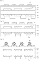
- FIG. 1 is a view showing a package system according to the related art.
- the package system includes a semiconductor package substrate 10, a dummy die 20, and a memory chip 30.
- the semiconductor package substrate 10 includes at least one circuit pattern formed on an insulation substrate.
- a protection layer for protecting the circuit pattern is formed on the circuit pattern (uppermost layer of the semiconductor package substrate 10).
- the memory chip 30 may be a NAND flash memory chip.
- the dummy die 20 is formed between the semiconductor substrate 10 and the memory chip 30.
- the dummy die 20 provides an attaching space for allowing the memory chip 30 to be attached onto the semiconductor substrate 10 while spacing the semiconductor substrate 10 from the memory chip 30.
- the dummy die 20 is formed of an expensive silicon material, a cost of the entire package system is increased.
- the silicon dummy die 20 has a predetermined thickness, the entire thickness of the package system is increased.
- the embodiment provides a semiconductor package substrate having a novel structure, a package system using the same, and a method for manufacturing the same.
- the embodiment provides a semiconductor package substrate capable of improving the productivity of a package system and reducing the cost of the package system.
- the copper pad and the adhesive member are formed on the semiconductor package without the expensive dummy die, so that the productivity of a package system can be improved and the product cost can be reduced
- the pad is formed by using the stack structure of multiple layers having different widths, thereby improving the adhesive strength with the adhesive member, so that the reliability of the semiconductor package substrate can be improved.
- the copper ball is used instead of the expensive dummy die, so that the fine pitch can be realized.
- the second adhesive member is formed by using the copper core solder ball, so that the high stand-off height can be maintained after the reflow process has been performed. Accordingly, the reliability of the semiconductor package substrate can be improved.
- a predetermined part when a predetermined part "includes" a predetermined component, the predetermined part does not exclude other components, but may further include other components if there is a specific opposite description.
- the embodiment provides a semiconductor package substrate capable of improving the productivity of a package system and reducing the product cost by forming a copper pad and an adhesive member on the semiconductor package substrate through a hybrid bump technology without using an expensive dummy die.
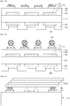
- FIG. 2 is a view showing a semiconductor package substrate according to a first embodiment.
- a semiconductor package substrate 100 includes an insulating substrate 110, a circuit pattern 125 formed on at least one surface of the insulating substrate 110, a protective layer 130 formed on the insulating substrate 110 to protect the circuit pattern 120, a first adhesive member 145 formed on the circuit pattern 125 formed on an opposite surface to a surface, on which a semiconductor chip 300 (which will be described layer) is formed, in the insulating substrate 110, a pad 170 on the protective layer 130 provided on the top surface of the insulating substrate 110, and a second adhesive member 180 formed on the pad 170.
- the insulating plate 110 may include thermosetting substrate, thermoplastic polymer substrate, a ceramic substrate, an organic-inorganic composite material substrate, or a glass fiber impregnation substrate. If the insulating plate 110 includes a polymer resin, the insulating plate 110 may include an epoxy-based insulating resin, or may include polyimide-based resin.
- the insulating plate 110 is formed on at least one surface thereof with the circuit pattern 125.
- circuit patterns 125 may include conductive material, and may be formed by simultaneously patterning a copper film formed on both surfaces of the insulating substrate 110.
- the circuit pattern 125 may be made of the alloy including copper (Cu) and may have surface roughness.
- the insulating substrate 110 is provided thereon with the protective layer 130 covering the circuit pattern 125 formed on the top surface of the insulating substrate 110 while exposing a portion of the surface of the circuit pattern 125 formed on the bottom surface of the insulating substrate 110.
- the protective layer 130 is to protect the surface of the insulating substrate 110.
- the protective layer 130 is formed throughout the entire surface of the insulating substrate 110.
- the protective layer 130 has an opening (not shown) to open the surface of the circuit pattern 125 to be exposed, that is, the surface of the stacking structure of the circuit pattern 125 formed on the bottom surface of the insulating substrate 110.
- the protective layer 130 may include at least one layer including one of solder resist (SR), an oxide, and gold (Au).
- SR solder resist
- Au gold
- the first adhesive member 145 is formed on the surface of the circuit pattern 125 exposed through the protective layer 130.
- the first adhesive member 145 is formed for the purpose of attaching a conductive ball to the insulating substrate 110 in order to package the semiconductor package substrate 100 together with an additional substrate thereafter.
- the protective layer 130 is provided thereon with the pad 170.
- the pad 170 is formed on the protective layer 130 to cover the entire surface of the circuit pattern 125, and does not make contact with the insulating substrate 110 or the circuit pattern 125.
- the pad 170 may include a conductive material.
- the pad 170 may include copper (Cu).
- the pad 170 is formed on the protective layer 130 for the purpose of attaching the semiconductor chip onto the semiconductor package substrate 100 thereafter.
- a dummy die including silicon is formed on the semiconductor package substrate regardless of the fabrication of the semiconductor package substrate 100.
- the pad 170 is formed on the protective layer 130 through a hybrid bump technology in the fabrication process of the semiconductor package
- the second adhesive member 180 is formed on the pad 170.
- the second adhesive member 180 is formed on the pad 170 to provide the adhesive strength between the semiconductor chip 300 and the semiconductor package substrate 100.
- the second adhesive member 180 may have the typical form of a solder ball. Alternatively, the second adhesive member 180 may be formed by using an adhesive paste or a copper core solder ball.
- the adhesive paste may include a conductive material for the electrical conduction. If the adhesive paste includes the conductive material, the conductive material may preferably include one selected from the group consisting of copper (Cu), silver (Ag), gold (Au), aluminum (Al), a carbon nano-tube, and the combination thereof.
- the copper pad and the adhesive member are formed on the semiconductor package substrate without the expensive dummy die, so that the productivity of a package system can be improved and the product cost can be reduced
- the copper ball is used instead of the expensive dummy die, so that the fine pitch is possible.
- the second adhesive member is formed by using a copper core solder ball 188, so that the high stand-off height can be maintained after the reflow process has been performed. Accordingly, the reliability of the semiconductor package substrate can be improved.
- FIGS. 3 to 15 are sectional views showing a method for fabricating the semiconductor package substrate shown in FIG. 2 in the sequence of process steps.
- a metallic layer 120 is stacked on at least one surface of the insulating substrate 110.
- the stack structure of the insulating layer and the metallic layer 120 may be a copper clad laminate (CCL) structure.
- the metallic layer 120 may be formed on the insulating substrate 110 by performing an electroless plating scheme. If the metallic layer 120 is formed through the electroless plating scheme, the roughness is applied to the surface of the insulating substrate 110, so that the plating process can be smoothly performed.
- the insulating substrate 110 may include epoxy-based resin or polyimide-based resin instead of the expensive ceramic material representing high thermal conductivity.
- the metallic layer 120 may include a copper thin film including copper high electrical conductivity and low resistance.
- the circuit pattern 125 is formed by etching metallic layers 120, which are formed at the upper and lower portions of the insulating substrate 110, at a predetermined pattern.
- the circuit pattern 125 may be formed through the etching process based on the photolithography process or through a laser process to directly form a pattern by using the laser.
- circuit pattern 125 may be formed on the upper and lower portions of the insulating substrate 110. Alternatively, the circuit pattern 125 may be formed only on the upper portion of the insulating substrate 110.
- the protective layer 130 is formed on the upper and lower portions of the insulating substrate 110 to bury the circuit pattern 125.
- the protective layer 130 is to protect the surface of the insulating substrate 110 or the circuit pattern 125.
- the protective layer 130 may include at least one layer including one of solder resist (SR), an oxide, and gold (Au).
- the protective layer 130 formed on the lower portion of the insulating substrate 110 is processed, thereby exposing the surface of the circuit pattern 125 formed on the bottom surface of the insulating substrate 110.
- the protective layer 130 formed under the insulating substrate 110 is processed by a laser to form the opening 140 to expose the surface of the circuit pattern 125 formed under the insulating substrate 110.
- the laser process is a cutting scheme to melt and evaporate a portion of a material by concentrating optical energy on a surface so that the surface has a desired shape.
- the complex shape can be easily processed through a computer program, and mixed material, which may not be easily cut through another scheme, can be processed.
- the laser process has an advantage in that the cut diameter may be formed to at least 0,005 mm
- a laser drill for the laser process preferably includes an yttrium aluminum garnet (YAG), a CO 2 laser, or an ultraviolet (UV) laser.
- YAG laser may process both of the copper film and the insulating layer, and the CO 2 laser may process only the insulating layer.
- the laser process is performed by using the UV laser, so that the opening 140 having a smaller diameter may be formed.
- the opening 140 may expose only a portion of the circuit pattern 125.
- the opening 140 may have a width narrower than that of the circuit pattern 125, so that only the edge region of the circuit pattern 125 may be protected by the protective layer 130.
- the first adhesive member 145 is formed on the circuit pattern 125 exposed by the opening 140.
- the first adhesive member 145 may be formed by coating an adhesive paste on the circuit pattern 125 exposed through the opening 140 by employing the protective layer 130 as a mask.
- the first adhesive member 145 is used to attach the solder ball, which provides an adhesive strength, between the semiconductor package substrate 100 and another substrate, so that the semiconductor package 100 is attached to the substrate.
- a plating seed layer 150 is formed on the protective layer 130 formed at the upper portion of the insulating substrate 110 as shown in FIG. 8 .
- the plating seed layer 150 may be formed through the chemical copper plating scheme.
- the chemical copper plating scheme may be performed in the sequence of a degreasing process, a soft etching process, a pre-catalyst process, a catalyst treatment process, an accelerator process, an electroless plating process, and an anti-oxidation treatment process.
- the copper plating scheme is classified into a heavy copper plating scheme (the thickness of about 2), a medium copper plating scheme (the thickness of 1 to 2), and a light copper plating scheme (the thickness of 1 or less) according to the thicknesses.
- the plating seed layer 150 having the thickness of 0.5 to 1.5 is formed through the medium copper plating scheme or the light copper plating scheme.
- a dry film 160 is formed on the plating seed layer 150.
- the dry film 160 may have a window to open a portion opposite to the region in which the pad 170 is formed.
- the dry film 160 may surround the entire surface of the plating seed layer 150, so that the window to open the region for the pad 170 may be formed.
- the pad 170 is formed on the plating seed layer 150 to bury the open window of the dry film 160.
- the pad 170 may be formed by electroless-plating metal such as copper (Cu) using the plating seed layer 150 as a seed layer.
- electroless-plating metal such as copper (Cu) using the plating seed layer 150 as a seed layer.
- the dry film 160 is delaminated.
- the plating seed layer 150 formed on the remaining region is removed except for the region for the pad 170.
- a portion of the plating seed layer 150 exists under the pad 170, so that the whole structure of the pad 170 includes the plating seed layer 150.
- the pad 170 including the plating seed layer 130 is formed on the protective layer 130.
- the second adhesive member 180 is formed on the pad 170.
- the second adhesive member 180 according to the first embodiment may be formed by using a solder ball, or a micro-ball.
- the second adhesive member 180 may be formed on the pad 170 through a flux printing scheme, a ball printing scheme, a reflow scheme, a deflux scheme, and a coining scheme.
- the second adhesive member 180 may be formed on the pad 170 by coating the adhesive paste 182 on the pad 170.
- the second adhesive member 180 may be formed on the pad 170 by using a copper core solder ball 188 including a copper ball 184 and a solder ball 186 surrounding the circumference of the copper ball 184.
- the pad 170 constituting the semiconductor package substrate 100 according to the first embodiment protrudes from the protective layer 130 and has the same width in the top and bottom surfaces.
- the copper pad and the adhesive member are formed on the semiconductor package substrate through the hybrid bump technology without the expensive dummy die, so that the productivity of a package system can be improved and the product cost can be reduced
- the second adhesive member 180 is formed by using the copper core solder ball 188, so that the high stand-off height can be maintained after the reflow process has been performed. Accordingly, the reliability of the semiconductor substrate can be improved.
- FIG. 16 is a view showing a semiconductor package substrate according to the second embodiment.
- a semiconductor package substrate 200 includes an insulating substrate 210, a circuit pattern 225 formed on at least one surface of the insulating substrate 210, a protective layer 230 formed on the insulating substrate 210 to protect the circuit pattern 225, a first adhesive member 245 formed on the circuit pattern 225 formed on an opposite surface to a surface, on which a semiconductor chip 300 (which will be described layer) is formed, in the insulating substrate 210, a pad 270 formed on the protective layer 230 provided on the top surface of the insulating substrate 210, and a second adhesive member 280 formed on the pad 270.
- the pad 170 includes a first pad 272 formed on the protective layer 230 and a second pad 274 formed on the first pad 272.
- the insulating plate 210 may include thermosetting substrate, thermoplastic polymer substrate, a ceramic substrate, an organic-inorganic composite material substrate, or a glass fiber impregnation substrate. If the insulating plate 210 includes a polymer resin, the insulating plate 210 may include an epoxy-based insulating resin, or may include polyimide-based resin.
- the circuit pattern 225 is formed on at least one surface of the insulating substrate 210.
- circuit patterns 225 may include conductive material, and may be formed by simultaneously patterning a copper film formed on both surfaces of the insulating substrate 210.
- the circuit pattern 225 may be made of the alloy including copper (Cu) and may have surface roughness.
- the insulating substrate 210 is provided thereon with the protective layer 230 covering the circuit pattern 225 formed on the top surface of the insulating substrate 210 while exposing a portion of the surface of the circuit pattern 225 formed on the bottom surface of the insulating substrate 210.
- the protective layer 230 is to protect the surface of the insulating substrate 210.
- the protective layer 230 is formed throughout the entire surface of the insulating substrate 210.
- the protective layer 230 has an opening (not shown) to open the surface of the circuit pattern 225 to be exposed, that is, the surface of the stacking structure of the circuit pattern 225 formed on the bottom surface of the insulating substrate 210.
- the protective layer 230 may include at least one layer including one of solder resist (SR), an oxide, and gold (Au).
- SR solder resist
- Au gold
- the first adhesive member 245 is formed on the surface of the circuit pattern 225 exposed through the protective layer 230.
- the first adhesive member 245 is formed for the purpose of attaching a conductive ball to the insulating substrate 210 in order to package the semiconductor package substrate 200 together with an additional substrate thereafter.
- the protective layer 230 is provided thereon with the pad 270.
- the pad 270 is formed on the protective layer 230 to cover the entire surface of the circuit pattern 225, and does not make contact with the insulating substrate 210 or the circuit pattern 225.
- the pad 270 may include a conductive material.
- the pad 270 may include copper (Cu).
- the pad 270 is formed on the protective layer 230 for the purpose of attaching the semiconductor chip 300 onto the semiconductor package substrate 200 thereafter.
- the pad 270 includes a plurality of layers.
- the pad 270 includes the first pad 272 formed on the protective layer 230 and the second pad 274 formed on the first pad 272.
- the first pad 272 has the same width in the top and bottom surfaces thereof, and is formed on the protective layer 230.
- the second pad 274 has the same width in the top and bottom surfaces thereof, and is formed on the first pad 272.
- the width of the first pad 272 may have the first width
- the second pad 274 may have the second width narrower than the first width
- the pad 170 is formed in a single layer for the purpose of the attachment to the semiconductor chip 300.
- the first and second pads 272 and 274 are formed in multiple layers for the purpose of the attachment to the semiconductor chip 300.
- the width of the second pad 274 is narrower than the width of the first pad 272, so that the adhesive strength with the second adhesive member, which is formed thereafter, may be improved.
- the second adhesive member 280 is formed on the second pad 274.
- the second adhesive member 280 is formed on the second pad 274 to provide the adhesive strength between the semiconductor chip 300 and the semiconductor package substrate 200.
- the second adhesive member 280 may have the typical form of a solder ball. Alternatively, the second adhesive member 280 may be formed by using the adhesive paste or the copper core solder ball.
- the adhesive paste may include a conductive material for the electrical conduction. If the adhesive paste includes the conductive material, the conductive material may preferably include one selected from the group consisting of copper (Cu), silver (Ag), gold (Au), aluminum (Al), a carbon nano-tube, and the combination thereof.
- FIGS. 17 to 23 are sectional views showing the method for fabricating the semiconductor package substrate shown in FIG. 16 in the sequence of the process steps.
- a metallic layer 220 is stacked on at least one surface of the insulating substrate 110.
- the stack structure of the insulating layer and the metallic layer 120 may be a typical copper clad laminate (CCL) structure.
- the metallic layer 220 may be formed on the insulating substrate 210 by performing an electroless plating scheme. If the metallic layer 220 is formed through the electroless plating scheme, the roughness is applied to the surface of the insulating substrate 210, so that the plating process can be smoothly performed.
- the insulating substrate 210 may include epoxy-based resin or polyimide-based resin instead of the expensive ceramic material representing high thermal conductivity.
- the metallic layer 220 may include a copper thin film including copper high electrical conductivity and low resistance.
- the circuit pattern 225 is formed by etching metallic layers 220, which are formed at the upper and lower portions of the insulating substrate 210, at a predetermined pattern.
- the circuit pattern 225 may be formed through the etching process based on the photolithography process or through a laser process to directly form a pattern by using the laser.
- circuit pattern 225 may be formed on the upper and lower portions of the insulating substrate 210. Alternatively, the circuit pattern 225 may be formed only on the upper portion of the insulating substrate 210.
- the protective layer 230 is formed on the upper and lower portions of the insulating substrate 210 to bury the circuit pattern 225.
- the protective layer 230 is to protect the surface of the insulating substrate 210 or the circuit pattern 225.
- the protective layer 230 may include at least one layer including one of solder resist (SR), an oxide, and gold (Au).
- the protective layer 230 formed on the lower portion of the insulating substrate 210 is processed, thereby exposing the surface of the circuit pattern 225 formed on the bottom surface of the insulating substrate 210.
- the first adhesive member 245 is formed on the circuit pattern 225.
- the plating seed layer 250 is formed on the protective layer 230 formed on the upper portion of the insulating substrate 210.
- the plating seed layer 250 may be formed through the chemical copper plating scheme.
- the chemical copper plating scheme may be performed in the sequence of a degreasing process, a soft etching process, a pre-catalyst process, a catalyst treatment process, an accelerator process, an electroless plating process, and an anti-oxidation treatment process.
- the copper plating scheme is classified into a heavy copper plating scheme (the thickness of about 2), a medium copper plating scheme (the thickness of 1 to 2), and a light copper plating scheme (the thickness of 1 or less) according to the thicknesses.
- the plating seed layer 250 having the thickness of 0.5 to 1.5 is formed through the medium copper plating scheme or the light copper plating scheme.
- a dry film may be formed on the plating seed layer 250.
- the dry film (not shown) may have a window to open a portion opposite to the region in which the pad 270 is formed.
- the first pad 272 is filled in the window of the dry film.
- the first pad 272 may be formed by electroless-plating metal such as copper (Cu) using the plating seed layer 250 as a seed layer.
- electroless-plating metal such as copper (Cu) using the plating seed layer 250 as a seed layer.
- the dry film 260 is formed on the plating seed layer 250.
- the dry film 260 may bury a portion of the surface of the first pad 272.
- the dry film 260 may have an opening to expose the surface of the first pad 272.
- the width of the opening of the dry film 260 is narrower than the width of the top surface of the first pad 272.
- the second pad 274 is formed on the first pad 272 by using the dry film 260 as a mask, so that the second pad 274 is filled in the opening.
- the width of the opening is narrow than the width of the top surface of the first pad 272. Accordingly, the width of the second pad 274 is narrower than the width of the first pad 272.
- the pad 270 includes the first and second pads 272 and 274.
- the first pad 272 has a width different from that of the second pad 274 because the adhesive strength with the second adhesive member 280 is increased, so that the reliability of the semiconductor package substrate 200 can be improved.
- the plating seed layer 250 is removed from a remaining portion except for the region for the first pad 272.
- a portion of the plating seed layer 250 exists under the first pad 272, so that the whole structure of the first pad 272 includes the plating seed layer 250.
- the first pad 272 including the plating seed layer 250 is formed on the protective layer 230, and the second pad 274 is formed with the width, which is narrower than that of the first pad 272, on the first pad 272
- the second adhesive member 280 is formed on the pad 270.
- the second adhesive member 280 may be formed by using the solder ball or the micro-ball.
- the second adhesive member 280 may be formed through processes such as a flux printing scheme, a ball printing scheme, a reflow scheme, a deflux scheme, and a coining scheme.
- the second adhesive member may be formed by coating adhesive paste.
- the second adhesive member may be formed by using a copper core solder ball including a copper ball and a solder ball surrounding the circumference of the copper ball.
- the copper pad and the adhesive member are formed on the semiconductor package substrate through the hybrid bump technology without the expensive dummy die, so that the productivity of a package system can be improved and the product cost can be reduced
- the pad is formed by using the stack structure of multiple layers, thereby improving the adhesive strength with the adhesive member, so that the reliability of the semiconductor package substrate can be improved.
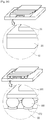
- FIGS. 24 and 25 are views showing a package system according to the embodiment.
- the package system includes the semiconductor package substrate 100 and the memory chip 300 formed on the semiconductor package substrate 100.
- the memory chip 300 may include a NAND flash memory chip.
- the memory chip 300 is attached to the semiconductor package substrate 100 by the pad 170 and the second adhesive member 180 which are formed on the semiconductor package substrate 100.
- the memory chip 300 is attached to the pad 170 and the second adhesive member 180 through a hybrid bump technology during the process of fabricating the semiconductor package substrate 100 without using an expensive dummy die separately from the process of fabricating the semiconductor package substrate 100 in order to attach the memory chip 300.
- FIG. 26 illustrates the comparison in the package system between the related art and the embodiment.
- an expensive dummy die 20 is formed on the package substrate 10, and a memory chip 30 is formed on the dummy die 20.
- the process of fabricating the package system according to the related art is mainly divided into three steps.
- the first step is to fabricate the package substrate 10.
- the second step is to form the dummy die 20 on the fabricated package substrate 10.
- the first and second steps are not performed at once, but performed through a plurality of sub-steps.
- the third step is to form the semiconductor chip 30 on the dummy die 20.
- the memory chip 300 is attached onto the pad 170 and the second adhesive member 180 through the hybrid bump technology.
- the process of fabricating the package system according to the embodiment is mainly divided into two sub-steps.
- the first step is to fabricate the package substrate 100.
- the step of fabricating the package substrate 100 includes the step of forming the pad 170 and the second adhesive member 180 formed through the hybrid bump technology.
- the second step is to attach the memory chip 300 onto the pad 170 and the second adhesive member 180 formed through the hybrid bump technology.
- the memory chip 300 is attached onto the pad 170 and the second adhesive member 180 formed through the hybrid bump technology without using the expensive dummy die, so that the fabrication cost can be reduced, and the fabrication process can be simplified.
Landscapes
- Engineering & Computer Science (AREA)
- Microelectronics & Electronic Packaging (AREA)
- Structures For Mounting Electric Components On Printed Circuit Boards (AREA)
- Production Of Multi-Layered Print Wiring Board (AREA)
- Ceramic Engineering (AREA)
- Internal Circuitry In Semiconductor Integrated Circuit Devices (AREA)
Claims (4)
- Un substrat (10) de boîtier de semi-conducteurs comprenant :un substrat isolant (210) ;une configuration de circuit (225) sur un premier côté et sur un côté opposé du substrat isolant (210) ;une réserve de soudure (230) formée sur le substrat isolant (210) pour recouvrir la configuration de circuit sur le premier côté et recouvrant partiellement la configuration de circuit sur le côté opposé du substrat isolant (210), la réserve de soudure sur le côté opposé de le substrat isolant (210) ayant au moins une ouverture pour exposer une surface de la configuration de circuit sur le côté opposé du substrat isolant (210), caractérisé en ce qu'il comprend en outre :une couche (250) de germes de placage sur la réserve de soudure (230) sur le premier côté du substrat isolant (210) tout en faisant saillie d'une surface de la réserve de soudure (230) ayant une largeur inférieure et une largeur supérieure égales l'une à l'autre ;un premier coussinet (272) situé sur la couche (250) de germes de placage et ayant une largeur inférieure et une largeur supérieure égales l'une à l'autre ;un deuxième coussinet (274) situé sur le premier coussinet (272) et ayant une largeur inférieure et une largeur supérieure égales l'une à l'autre ; etun élément adhésif (280) situé sur le deuxième coussinet (274),une surface inférieure de la couche de germes de placage étant directement mise en contact avec la surface supérieure de la réserve de soudure ;l'ouverture de la réserve de soudure sur le côté opposé du substrat d'isolation (210) ayant une largeur plus réduite que celle de la configuration de circuit, et une zone de bordure de la configuration de circuit est recouverte par la réserve de soudure,la réserve de soudure (230) sur le côté opposé du substrat isolant (210) étant exposée à l'extérieur,une puce de mémoire étant fixée sur l'élément adhésif et supportée par le premier coussinet et le deuxième coussinet,la couche (250) de germes de placage et le premier coussinet (272) ayant une première largeur,le deuxième coussinet (274) ayant une deuxième largeur plus réduite que la première largeur.
- Le substrat (10) de boîtier de semi-conducteurs selon la revendication 1, dans lequel l'élément adhésif (280) comprend l'une parmi une bille à souder, une microbille, une pâte adhésive et une bille à souder à noyau en cuivre.
- Un procédé de fabrication d'un système de boîtier de semi-conducteurs, le procédé comprenant :le fait de former une configuration de circuit (225) sur une première surface d'un substrat isolant (210) et sur une surface opposée du substrat isolant ;le fait de former une réserve de soudure (230) sur le substrat isolant (210) pour recouvrir la configuration de circuit (225) sur la première surface et recouvrir partiellement la configuration de circuit (225) sur la surface opposée du substrat isolant (210), la réserve de soudure (230) sur la surface opposée du substrat isolant (210) ayant au moins une ouverture pour exposer une surface de la configuration de circuit (225) présente sur la surface opposée du substrat isolant (210), caractérisé par :le fait de former une couche (250) de germes de placage sur la réserve de soudure (230) sur la première surface du substrat isolant (210) ;le fait de fixer un film sec (260), qui a une ouverture pour exposer une zone pour la formation d'un coussinet, sur la couche (250) de germes de placage ;le fait de former le coussinet sur la couche protectrice (230) en remplissant l'ouverture du film sec (260) ; etle fait de former un élément adhésif (280) sur le coussinet formé.le coussinet formé comprenant la couche (250) de germes de placage formée au niveau d'une partie inférieure du coussinet,une surface supérieure de la couche de germes de placage étant aménagée en saillie d'une surface supérieure de la réserve de soudure ;une surface inférieure de la couche de germes de placage étant directement mise en contact avec la surface supérieure de la réserve de soudure,l'ouverture de la réserve de soudure sur la surface opposée de la couche isolante a une largeur plus réduite que celle de la configuration de circuit, et une zone de bordure de la configuration de circuit est recouverte par la réserve de soudure,la réserve de soudure sur la surface opposée de la couche isolante étant exposée à l'extérieur,une puce de mémoire étant fixée sur l'élément adhésif et est supportée par le coussinet,la fixation du film sec (260), qui a l'ouverture pour exposer la zone de formation du coussinet, sur la couche (250) de germes de placage comprenant :le fait de former un premier film sec, qui a une ouverture ayant une première largeur, sur la couche (250) de germes de placage ; etle fait de former un deuxième film sec, qui présente une ouverture ayant une deuxième largeur, sur le premier film sec ;la première largeur étant différente de la deuxième largeur,la formation du coussinet sur la couche protectrice (230) en remplissant l'ouverture du film sec comprenant :le fait de former un premier coussinet (272) en remplissant l'ouverture du premier film sec ;le fait de former un deuxième coussinet (274) en remplissant l'ouverture du deuxième film sec ; etle deuxième coussinet (274) étant plus étroit que le premier coussinet (272).
- Le procédé selon la revendication 3, dans lequel la formation de l'élément adhésif (280) sur le coussinet formé comprend le fait de former sur le coussinet au moins l'une parmi une bille à souder, une microbille, une pâte adhésive et une bille à souder à noyau en cuivre.
Applications Claiming Priority (2)
| Application Number | Priority Date | Filing Date | Title |
|---|---|---|---|
| KR1020120056356A KR101383002B1 (ko) | 2012-05-25 | 2012-05-25 | 반도체 패키지 기판, 이를 이용한 패키지 시스템 및 이의 제조 방법 |
| PCT/KR2013/004578 WO2013176519A1 (fr) | 2012-05-25 | 2013-05-24 | Substrat de boîtier de semi-conducteurs, système de boîtier utilisant un tel substrat et son procédé de fabrication |
Publications (3)
| Publication Number | Publication Date |
|---|---|
| EP2856502A1 EP2856502A1 (fr) | 2015-04-08 |
| EP2856502A4 EP2856502A4 (fr) | 2015-08-05 |
| EP2856502B1 true EP2856502B1 (fr) | 2020-08-05 |
Family
ID=49624126
Family Applications (1)
| Application Number | Title | Priority Date | Filing Date |
|---|---|---|---|
| EP13793826.2A Active EP2856502B1 (fr) | 2012-05-25 | 2013-05-24 | Substrat de boîtier de semi-conducteurs et son procédé de fabrication |
Country Status (6)
| Country | Link |
|---|---|
| US (1) | US10062623B2 (fr) |
| EP (1) | EP2856502B1 (fr) |
| KR (1) | KR101383002B1 (fr) |
| CN (1) | CN104396008B (fr) |
| TW (1) | TW201405736A (fr) |
| WO (1) | WO2013176519A1 (fr) |
Families Citing this family (7)
| Publication number | Priority date | Publication date | Assignee | Title |
|---|---|---|---|---|
| KR102212827B1 (ko) | 2014-06-30 | 2021-02-08 | 엘지이노텍 주식회사 | 인쇄회로기판, 패키지 기판 및 이의 제조 방법 |
| US9832860B2 (en) * | 2014-09-26 | 2017-11-28 | Intel Corporation | Panel level fabrication of package substrates with integrated stiffeners |
| KR102497595B1 (ko) * | 2016-01-05 | 2023-02-08 | 삼성전자주식회사 | 패키지 기판, 이를 제조하는 방법 및 패키지 기판을 포함하는 패키지 장치 |
| US10049996B2 (en) * | 2016-04-01 | 2018-08-14 | Intel Corporation | Surface finishes for high density interconnect architectures |
| TWI730843B (zh) * | 2020-07-15 | 2021-06-11 | 欣興電子股份有限公司 | 封裝載板及其製作方法 |
| KR102933098B1 (ko) * | 2020-10-23 | 2026-03-03 | 엘지이노텍 주식회사 | 인쇄회로기판 및 이의 제조 방법 |
| KR20230040809A (ko) * | 2021-09-16 | 2023-03-23 | 엘지이노텍 주식회사 | 회로기판 및 이를 포함하는 패키지 기판 |
Family Cites Families (32)
| Publication number | Priority date | Publication date | Assignee | Title |
|---|---|---|---|---|
| JPS62194652A (ja) * | 1986-02-21 | 1987-08-27 | Hitachi Ltd | 半導体装置 |
| JPH0637143A (ja) * | 1992-07-15 | 1994-02-10 | Toshiba Corp | 半導体装置および半導体装置の製造方法 |
| US5917157A (en) * | 1994-12-12 | 1999-06-29 | Remsburg; Ralph | Multilayer wiring board laminate with enhanced thermal dissipation to dielectric substrate laminate |
| US5926731A (en) | 1997-07-02 | 1999-07-20 | Delco Electronics Corp. | Method for controlling solder bump shape and stand-off height |
| JPH11340265A (ja) * | 1998-05-22 | 1999-12-10 | Sony Corp | 半導体装置及びその製造方法 |
| KR20000002962A (ko) * | 1998-06-24 | 2000-01-15 | 윤종용 | 웨이퍼레벨의 칩스케일 패키지 및 그 제조방법 |
| US6724084B1 (en) * | 1999-02-08 | 2004-04-20 | Rohm Co., Ltd. | Semiconductor chip and production thereof, and semiconductor device having semiconductor chip bonded to solid device |
| JP2003100801A (ja) | 2001-09-25 | 2003-04-04 | Mitsubishi Electric Corp | 半導体装置 |
| JP2003110052A (ja) | 2001-10-02 | 2003-04-11 | Nec Toppan Circuit Solutions Inc | 半導体装置用基板 |
| TWI245402B (en) * | 2002-01-07 | 2005-12-11 | Megic Corp | Rod soldering structure and manufacturing process thereof |
| JP3825370B2 (ja) * | 2002-05-24 | 2006-09-27 | 富士通株式会社 | 半導体装置の製造方法 |
| US6844626B2 (en) | 2003-05-23 | 2005-01-18 | Taiwan Semiconductor Manufacturing Company, Ltd. | Bond pad scheme for Cu process |
| US6849944B2 (en) * | 2003-05-30 | 2005-02-01 | Texas Instruments Incorporated | Using a supporting structure to control collapse of a die towards a die pad during a reflow process for coupling the die to the die pad |
| TWI286372B (en) * | 2003-08-13 | 2007-09-01 | Phoenix Prec Technology Corp | Semiconductor package substrate with protective metal layer on pads formed thereon and method for fabricating the same |
| CN100342526C (zh) | 2003-08-22 | 2007-10-10 | 全懋精密科技股份有限公司 | 有电性连接垫金属保护层的半导体封装基板结构及其制法 |
| JP2005310837A (ja) | 2004-04-16 | 2005-11-04 | Elpida Memory Inc | 半導体装置及びその製造方法 |
| TWI259572B (en) * | 2004-09-07 | 2006-08-01 | Siliconware Precision Industries Co Ltd | Bump structure of semiconductor package and fabrication method thereof |
| KR100645624B1 (ko) * | 2005-01-24 | 2006-11-14 | 삼성전기주식회사 | 솔더 접합 구조 |
| KR100691151B1 (ko) * | 2005-02-24 | 2007-03-09 | 삼성전기주식회사 | 솔더범프 앵커시스템 |
| JP4542926B2 (ja) * | 2005-03-15 | 2010-09-15 | 株式会社東芝 | 接合方法 |
| JP4404139B2 (ja) | 2005-10-26 | 2010-01-27 | 株式会社村田製作所 | 積層型基板、電子装置および積層型基板の製造方法 |
| US7397121B2 (en) * | 2005-10-28 | 2008-07-08 | Megica Corporation | Semiconductor chip with post-passivation scheme formed over passivation layer |
| CN100583424C (zh) | 2006-09-20 | 2010-01-20 | 欣兴电子股份有限公司 | 封装基板 |
| TWI331388B (en) | 2007-01-25 | 2010-10-01 | Advanced Semiconductor Eng | Package substrate, method of fabricating the same and chip package |
| TWI320680B (en) | 2007-03-07 | 2010-02-11 | Phoenix Prec Technology Corp | Circuit board structure and fabrication method thereof |
| TWI351729B (en) * | 2007-07-03 | 2011-11-01 | Siliconware Precision Industries Co Ltd | Semiconductor device and method for fabricating th |
| TWI387014B (zh) | 2008-06-05 | 2013-02-21 | 南茂科技股份有限公司 | 具有犧牲基板之晶粒重新配置結構及其封裝方法 |
| KR101055485B1 (ko) * | 2008-10-02 | 2011-08-08 | 삼성전기주식회사 | 범프볼을 갖는 반도체 패키지 |
| KR20110029466A (ko) * | 2009-09-15 | 2011-03-23 | 삼성전기주식회사 | 솔더 범프 형성 방법 및 이를 이용하여 제작한 패키지 기판 |
| KR101067216B1 (ko) | 2010-05-24 | 2011-09-22 | 삼성전기주식회사 | 인쇄회로기판 및 이를 구비하는 반도체 패키지 |
| US8227924B2 (en) * | 2010-07-13 | 2012-07-24 | Taiwan Semiconductor Manufacturing Company, Ltd. | Substrate stand-offs for semiconductor devices |
| US8912649B2 (en) * | 2011-08-17 | 2014-12-16 | Taiwan Semiconductor Manufacturing Company, Ltd. | Dummy flip chip bumps for reducing stress |
-
2012
- 2012-05-25 KR KR1020120056356A patent/KR101383002B1/ko active Active
-
2013
- 2013-05-24 TW TW102118455A patent/TW201405736A/zh unknown
- 2013-05-24 WO PCT/KR2013/004578 patent/WO2013176519A1/fr not_active Ceased
- 2013-05-24 US US14/401,602 patent/US10062623B2/en active Active
- 2013-05-24 EP EP13793826.2A patent/EP2856502B1/fr active Active
- 2013-05-24 CN CN201380033607.3A patent/CN104396008B/zh active Active
Non-Patent Citations (1)
| Title |
|---|
| None * |
Also Published As
| Publication number | Publication date |
|---|---|
| WO2013176519A1 (fr) | 2013-11-28 |
| CN104396008A (zh) | 2015-03-04 |
| EP2856502A1 (fr) | 2015-04-08 |
| TW201405736A (zh) | 2014-02-01 |
| KR101383002B1 (ko) | 2014-04-08 |
| US20150130060A1 (en) | 2015-05-14 |
| CN104396008B (zh) | 2017-08-11 |
| KR20130132173A (ko) | 2013-12-04 |
| US10062623B2 (en) | 2018-08-28 |
| EP2856502A4 (fr) | 2015-08-05 |
Similar Documents
| Publication | Publication Date | Title |
|---|---|---|
| EP2856502B1 (fr) | Substrat de boîtier de semi-conducteurs et son procédé de fabrication | |
| TWI508196B (zh) | 具有內建加強層之凹穴基板之製造方法 | |
| US9627309B2 (en) | Wiring substrate | |
| US9627308B2 (en) | Wiring substrate | |
| US20090090541A1 (en) | Stacked semiconductor device and fabricating method thereof | |
| TWI493671B (zh) | 具有支撐體的封裝基板及其製法、具有支撐體的封裝結構及其製法 | |
| US20130170148A1 (en) | Package carrier and manufacturing method thereof | |
| KR20140021910A (ko) | 코어기판 및 이를 이용한 인쇄회로기판 | |
| EP2856501B1 (fr) | Substrat de conditionnement semi-conducteur, système de conditionnement l'utilisant et son procédé de fabrication | |
| US10483194B2 (en) | Interposer substrate and method of fabricating the same | |
| CN100452396C (zh) | 半导体装置及其制造方法 | |
| JP7111457B2 (ja) | 半導体装置及びその製造方法 | |
| TW201603665A (zh) | 印刷電路板、用以製造其之方法及具有其之層疊封裝 | |
| CN102664170A (zh) | 半导体封装结构及其制造方法 | |
| US20090108444A1 (en) | Chip package structure and its fabrication method | |
| KR101996935B1 (ko) | 반도체 패키지 기판, 이를 이용한 패키지 시스템 및 이의 제조 방법 | |
| JP2013058775A (ja) | 半導体パッケージ基板の製造方法 | |
| CN104576402A (zh) | 封装载板及其制作方法 | |
| CN108461405B (zh) | 线路载板及其制造方法 | |
| KR101771801B1 (ko) | 인쇄회로기판 및 그 제조방법 | |
| US20230080101A1 (en) | Semiconductor package substrate, method of manufacturing the same, and semiconductor package | |
| CN100474541C (zh) | 芯片封装结构制造方法 | |
| US20110057318A1 (en) | Die Package | |
| KR20140076089A (ko) | 반도체 기판 및 그 제조 방법, 그리고 반도체 패키지 |
Legal Events
| Date | Code | Title | Description |
|---|---|---|---|
| PUAI | Public reference made under article 153(3) epc to a published international application that has entered the european phase |
Free format text: ORIGINAL CODE: 0009012 |
|
| 17P | Request for examination filed |
Effective date: 20141223 |
|
| AK | Designated contracting states |
Kind code of ref document: A1 Designated state(s): AL AT BE BG CH CY CZ DE DK EE ES FI FR GB GR HR HU IE IS IT LI LT LU LV MC MK MT NL NO PL PT RO RS SE SI SK SM TR |
|
| AX | Request for extension of the european patent |
Extension state: BA ME |
|
| RA4 | Supplementary search report drawn up and despatched (corrected) |
Effective date: 20150703 |
|
| RIC1 | Information provided on ipc code assigned before grant |
Ipc: H01L 23/15 20060101ALI20150629BHEP Ipc: H01L 23/12 20060101AFI20150629BHEP |
|
| DAX | Request for extension of the european patent (deleted) | ||
| RAP1 | Party data changed (applicant data changed or rights of an application transferred) |
Owner name: LG INNOTEK CO., LTD. |
|
| STAA | Information on the status of an ep patent application or granted ep patent |
Free format text: STATUS: EXAMINATION IS IN PROGRESS |
|
| 17Q | First examination report despatched |
Effective date: 20190816 |
|
| GRAP | Despatch of communication of intention to grant a patent |
Free format text: ORIGINAL CODE: EPIDOSNIGR1 |
|
| STAA | Information on the status of an ep patent application or granted ep patent |
Free format text: STATUS: GRANT OF PATENT IS INTENDED |
|
| INTG | Intention to grant announced |
Effective date: 20200228 |
|
| GRAS | Grant fee paid |
Free format text: ORIGINAL CODE: EPIDOSNIGR3 |
|
| GRAA | (expected) grant |
Free format text: ORIGINAL CODE: 0009210 |
|
| STAA | Information on the status of an ep patent application or granted ep patent |
Free format text: STATUS: THE PATENT HAS BEEN GRANTED |
|
| AK | Designated contracting states |
Kind code of ref document: B1 Designated state(s): AL AT BE BG CH CY CZ DE DK EE ES FI FR GB GR HR HU IE IS IT LI LT LU LV MC MK MT NL NO PL PT RO RS SE SI SK SM TR |
|
| REG | Reference to a national code |
Ref country code: GB Ref legal event code: FG4D |
|
| REG | Reference to a national code |
Ref country code: CH Ref legal event code: EP |
|
| REG | Reference to a national code |
Ref country code: AT Ref legal event code: REF Ref document number: 1299917 Country of ref document: AT Kind code of ref document: T Effective date: 20200815 |
|
| REG | Reference to a national code |
Ref country code: DE Ref legal event code: R096 Ref document number: 602013071355 Country of ref document: DE |
|
| REG | Reference to a national code |
Ref country code: IE Ref legal event code: FG4D |
|
| REG | Reference to a national code |
Ref country code: LT Ref legal event code: MG4D |
|
| REG | Reference to a national code |
Ref country code: NL Ref legal event code: MP Effective date: 20200805 |
|
| REG | Reference to a national code |
Ref country code: AT Ref legal event code: MK05 Ref document number: 1299917 Country of ref document: AT Kind code of ref document: T Effective date: 20200805 |
|
| PG25 | Lapsed in a contracting state [announced via postgrant information from national office to epo] |
Ref country code: PT Free format text: LAPSE BECAUSE OF FAILURE TO SUBMIT A TRANSLATION OF THE DESCRIPTION OR TO PAY THE FEE WITHIN THE PRESCRIBED TIME-LIMIT Effective date: 20201207 Ref country code: ES Free format text: LAPSE BECAUSE OF FAILURE TO SUBMIT A TRANSLATION OF THE DESCRIPTION OR TO PAY THE FEE WITHIN THE PRESCRIBED TIME-LIMIT Effective date: 20200805 Ref country code: BG Free format text: LAPSE BECAUSE OF FAILURE TO SUBMIT A TRANSLATION OF THE DESCRIPTION OR TO PAY THE FEE WITHIN THE PRESCRIBED TIME-LIMIT Effective date: 20201105 Ref country code: LT Free format text: LAPSE BECAUSE OF FAILURE TO SUBMIT A TRANSLATION OF THE DESCRIPTION OR TO PAY THE FEE WITHIN THE PRESCRIBED TIME-LIMIT Effective date: 20200805 Ref country code: HR Free format text: LAPSE BECAUSE OF FAILURE TO SUBMIT A TRANSLATION OF THE DESCRIPTION OR TO PAY THE FEE WITHIN THE PRESCRIBED TIME-LIMIT Effective date: 20200805 Ref country code: AT Free format text: LAPSE BECAUSE OF FAILURE TO SUBMIT A TRANSLATION OF THE DESCRIPTION OR TO PAY THE FEE WITHIN THE PRESCRIBED TIME-LIMIT Effective date: 20200805 Ref country code: GR Free format text: LAPSE BECAUSE OF FAILURE TO SUBMIT A TRANSLATION OF THE DESCRIPTION OR TO PAY THE FEE WITHIN THE PRESCRIBED TIME-LIMIT Effective date: 20201106 Ref country code: NO Free format text: LAPSE BECAUSE OF FAILURE TO SUBMIT A TRANSLATION OF THE DESCRIPTION OR TO PAY THE FEE WITHIN THE PRESCRIBED TIME-LIMIT Effective date: 20201105 Ref country code: FI Free format text: LAPSE BECAUSE OF FAILURE TO SUBMIT A TRANSLATION OF THE DESCRIPTION OR TO PAY THE FEE WITHIN THE PRESCRIBED TIME-LIMIT Effective date: 20200805 Ref country code: SE Free format text: LAPSE BECAUSE OF FAILURE TO SUBMIT A TRANSLATION OF THE DESCRIPTION OR TO PAY THE FEE WITHIN THE PRESCRIBED TIME-LIMIT Effective date: 20200805 |
|
| PG25 | Lapsed in a contracting state [announced via postgrant information from national office to epo] |
Ref country code: RS Free format text: LAPSE BECAUSE OF FAILURE TO SUBMIT A TRANSLATION OF THE DESCRIPTION OR TO PAY THE FEE WITHIN THE PRESCRIBED TIME-LIMIT Effective date: 20200805 Ref country code: NL Free format text: LAPSE BECAUSE OF FAILURE TO SUBMIT A TRANSLATION OF THE DESCRIPTION OR TO PAY THE FEE WITHIN THE PRESCRIBED TIME-LIMIT Effective date: 20200805 Ref country code: PL Free format text: LAPSE BECAUSE OF FAILURE TO SUBMIT A TRANSLATION OF THE DESCRIPTION OR TO PAY THE FEE WITHIN THE PRESCRIBED TIME-LIMIT Effective date: 20200805 Ref country code: LV Free format text: LAPSE BECAUSE OF FAILURE TO SUBMIT A TRANSLATION OF THE DESCRIPTION OR TO PAY THE FEE WITHIN THE PRESCRIBED TIME-LIMIT Effective date: 20200805 Ref country code: IS Free format text: LAPSE BECAUSE OF FAILURE TO SUBMIT A TRANSLATION OF THE DESCRIPTION OR TO PAY THE FEE WITHIN THE PRESCRIBED TIME-LIMIT Effective date: 20201205 |
|
| PG25 | Lapsed in a contracting state [announced via postgrant information from national office to epo] |
Ref country code: DK Free format text: LAPSE BECAUSE OF FAILURE TO SUBMIT A TRANSLATION OF THE DESCRIPTION OR TO PAY THE FEE WITHIN THE PRESCRIBED TIME-LIMIT Effective date: 20200805 Ref country code: CZ Free format text: LAPSE BECAUSE OF FAILURE TO SUBMIT A TRANSLATION OF THE DESCRIPTION OR TO PAY THE FEE WITHIN THE PRESCRIBED TIME-LIMIT Effective date: 20200805 Ref country code: EE Free format text: LAPSE BECAUSE OF FAILURE TO SUBMIT A TRANSLATION OF THE DESCRIPTION OR TO PAY THE FEE WITHIN THE PRESCRIBED TIME-LIMIT Effective date: 20200805 Ref country code: RO Free format text: LAPSE BECAUSE OF FAILURE TO SUBMIT A TRANSLATION OF THE DESCRIPTION OR TO PAY THE FEE WITHIN THE PRESCRIBED TIME-LIMIT Effective date: 20200805 Ref country code: SM Free format text: LAPSE BECAUSE OF FAILURE TO SUBMIT A TRANSLATION OF THE DESCRIPTION OR TO PAY THE FEE WITHIN THE PRESCRIBED TIME-LIMIT Effective date: 20200805 |
|
| REG | Reference to a national code |
Ref country code: DE Ref legal event code: R097 Ref document number: 602013071355 Country of ref document: DE |
|
| PG25 | Lapsed in a contracting state [announced via postgrant information from national office to epo] |
Ref country code: AL Free format text: LAPSE BECAUSE OF FAILURE TO SUBMIT A TRANSLATION OF THE DESCRIPTION OR TO PAY THE FEE WITHIN THE PRESCRIBED TIME-LIMIT Effective date: 20200805 |
|
| PLBE | No opposition filed within time limit |
Free format text: ORIGINAL CODE: 0009261 |
|
| STAA | Information on the status of an ep patent application or granted ep patent |
Free format text: STATUS: NO OPPOSITION FILED WITHIN TIME LIMIT |
|
| PG25 | Lapsed in a contracting state [announced via postgrant information from national office to epo] |
Ref country code: SK Free format text: LAPSE BECAUSE OF FAILURE TO SUBMIT A TRANSLATION OF THE DESCRIPTION OR TO PAY THE FEE WITHIN THE PRESCRIBED TIME-LIMIT Effective date: 20200805 |
|
| 26N | No opposition filed |
Effective date: 20210507 |
|
| PG25 | Lapsed in a contracting state [announced via postgrant information from national office to epo] |
Ref country code: IT Free format text: LAPSE BECAUSE OF FAILURE TO SUBMIT A TRANSLATION OF THE DESCRIPTION OR TO PAY THE FEE WITHIN THE PRESCRIBED TIME-LIMIT Effective date: 20200805 |
|
| PG25 | Lapsed in a contracting state [announced via postgrant information from national office to epo] |
Ref country code: SI Free format text: LAPSE BECAUSE OF FAILURE TO SUBMIT A TRANSLATION OF THE DESCRIPTION OR TO PAY THE FEE WITHIN THE PRESCRIBED TIME-LIMIT Effective date: 20200805 |
|
| REG | Reference to a national code |
Ref country code: CH Ref legal event code: PL |
|
| GBPC | Gb: european patent ceased through non-payment of renewal fee |
Effective date: 20210524 |
|
| PG25 | Lapsed in a contracting state [announced via postgrant information from national office to epo] |
Ref country code: CH Free format text: LAPSE BECAUSE OF NON-PAYMENT OF DUE FEES Effective date: 20210531 Ref country code: LI Free format text: LAPSE BECAUSE OF NON-PAYMENT OF DUE FEES Effective date: 20210531 Ref country code: LU Free format text: LAPSE BECAUSE OF NON-PAYMENT OF DUE FEES Effective date: 20210524 Ref country code: MC Free format text: LAPSE BECAUSE OF FAILURE TO SUBMIT A TRANSLATION OF THE DESCRIPTION OR TO PAY THE FEE WITHIN THE PRESCRIBED TIME-LIMIT Effective date: 20200805 |
|
| REG | Reference to a national code |
Ref country code: BE Ref legal event code: MM Effective date: 20210531 |
|
| PG25 | Lapsed in a contracting state [announced via postgrant information from national office to epo] |
Ref country code: IE Free format text: LAPSE BECAUSE OF NON-PAYMENT OF DUE FEES Effective date: 20210524 Ref country code: GB Free format text: LAPSE BECAUSE OF NON-PAYMENT OF DUE FEES Effective date: 20210524 |
|
| PG25 | Lapsed in a contracting state [announced via postgrant information from national office to epo] |
Ref country code: BE Free format text: LAPSE BECAUSE OF NON-PAYMENT OF DUE FEES Effective date: 20210531 |
|
| PG25 | Lapsed in a contracting state [announced via postgrant information from national office to epo] |
Ref country code: HU Free format text: LAPSE BECAUSE OF FAILURE TO SUBMIT A TRANSLATION OF THE DESCRIPTION OR TO PAY THE FEE WITHIN THE PRESCRIBED TIME-LIMIT; INVALID AB INITIO Effective date: 20130524 |
|
| PG25 | Lapsed in a contracting state [announced via postgrant information from national office to epo] |
Ref country code: CY Free format text: LAPSE BECAUSE OF FAILURE TO SUBMIT A TRANSLATION OF THE DESCRIPTION OR TO PAY THE FEE WITHIN THE PRESCRIBED TIME-LIMIT Effective date: 20200805 |
|
| PG25 | Lapsed in a contracting state [announced via postgrant information from national office to epo] |
Ref country code: MK Free format text: LAPSE BECAUSE OF FAILURE TO SUBMIT A TRANSLATION OF THE DESCRIPTION OR TO PAY THE FEE WITHIN THE PRESCRIBED TIME-LIMIT Effective date: 20200805 |
|
| PG25 | Lapsed in a contracting state [announced via postgrant information from national office to epo] |
Ref country code: MT Free format text: LAPSE BECAUSE OF FAILURE TO SUBMIT A TRANSLATION OF THE DESCRIPTION OR TO PAY THE FEE WITHIN THE PRESCRIBED TIME-LIMIT Effective date: 20200805 |
|
| PGFP | Annual fee paid to national office [announced via postgrant information from national office to epo] |
Ref country code: DE Payment date: 20250422 Year of fee payment: 13 |
|
| PGFP | Annual fee paid to national office [announced via postgrant information from national office to epo] |
Ref country code: FR Payment date: 20250422 Year of fee payment: 13 |
|
| REG | Reference to a national code |
Ref country code: DE Ref legal event code: R079 Ref document number: 602013071355 Country of ref document: DE Free format text: PREVIOUS MAIN CLASS: H01L0023120000 Ipc: H10W0070600000 |
|
| PG25 | Lapsed in a contracting state [announced via postgrant information from national office to epo] |
Ref country code: TR Free format text: LAPSE BECAUSE OF FAILURE TO SUBMIT A TRANSLATION OF THE DESCRIPTION OR TO PAY THE FEE WITHIN THE PRESCRIBED TIME-LIMIT Effective date: 20200805 |