EP2877227B1 - Kanüle - Google Patents
Kanüle Download PDFInfo
- Publication number
- EP2877227B1 EP2877227B1 EP13745009.4A EP13745009A EP2877227B1 EP 2877227 B1 EP2877227 B1 EP 2877227B1 EP 13745009 A EP13745009 A EP 13745009A EP 2877227 B1 EP2877227 B1 EP 2877227B1
- Authority
- EP
- European Patent Office
- Prior art keywords
- cannula
- section
- protective element
- sections
- cannula section
- Prior art date
- Legal status (The legal status is an assumption and is not a legal conclusion. Google has not performed a legal analysis and makes no representation as to the accuracy of the status listed.)
- Active
Links
Images







Classifications
-
- A—HUMAN NECESSITIES
- A61—MEDICAL OR VETERINARY SCIENCE; HYGIENE
- A61M—DEVICES FOR INTRODUCING MEDIA INTO, OR ONTO, THE BODY; DEVICES FOR TRANSDUCING BODY MEDIA OR FOR TAKING MEDIA FROM THE BODY; DEVICES FOR PRODUCING OR ENDING SLEEP OR STUPOR
- A61M25/00—Catheters; Hollow probes
- A61M25/01—Introducing, guiding, advancing, emplacing or holding catheters
- A61M25/06—Body-piercing guide needles or the like
- A61M25/0612—Devices for protecting the needle; Devices to help insertion of the needle, e.g. wings or holders
- A61M25/0643—Devices having a blunt needle tip, e.g. due to an additional inner component
-
- A—HUMAN NECESSITIES
- A61—MEDICAL OR VETERINARY SCIENCE; HYGIENE
- A61M—DEVICES FOR INTRODUCING MEDIA INTO, OR ONTO, THE BODY; DEVICES FOR TRANSDUCING BODY MEDIA OR FOR TAKING MEDIA FROM THE BODY; DEVICES FOR PRODUCING OR ENDING SLEEP OR STUPOR
- A61M25/00—Catheters; Hollow probes
- A61M25/01—Introducing, guiding, advancing, emplacing or holding catheters
- A61M25/06—Body-piercing guide needles or the like
- A61M25/065—Guide needles
-
- A—HUMAN NECESSITIES
- A61—MEDICAL OR VETERINARY SCIENCE; HYGIENE
- A61B—DIAGNOSIS; SURGERY; IDENTIFICATION
- A61B17/00—Surgical instruments, devices or methods
- A61B17/34—Trocars; Puncturing needles
- A61B17/3415—Trocars; Puncturing needles for introducing tubes or catheters, e.g. gastrostomy tubes, drain catheters
-
- A—HUMAN NECESSITIES
- A61—MEDICAL OR VETERINARY SCIENCE; HYGIENE
- A61B—DIAGNOSIS; SURGERY; IDENTIFICATION
- A61B17/00—Surgical instruments, devices or methods
- A61B17/34—Trocars; Puncturing needles
- A61B17/3417—Details of tips or shafts, e.g. grooves, expandable, bendable; Multiple coaxial sliding cannulas, e.g. for dilating
- A61B17/3421—Cannulas
Definitions
- the invention relates to a cannula, in particular a suprapubic cannula for introducing a catheter into a body cavity, with a first cannula section in the form of a longitudinally cut first sleeve body, in particular with an arc of a circle or an arcuate geometry, and one connected to the latter when a catheter is inserted second cannula section in the form of a longitudinally cut second sleeve body, in particular with a circular arc geometry or an arcuate geometry, one of the cannula sections having a puncture tip in the distal end.
- a cannula is placed above the pubic bone perpendicular to the abdominal wall and into the bladder, in order to then insert a catheter through the cannula. The cannula is then pulled out. However, since this cannot be pulled over the base of the catheter, fissile cannulas are used. Such is e.g. B. the DE 42 00 255 A1 refer to.
- the cannula has two lines of weakness which run diametrically to one another, each half of the cannula having a handle in order to pull it in opposite directions, as a result of which the cannula separates in its longitudinal direction.
- a cannula of the type mentioned is the DE 33 47 150 C1 refer to.
- the cannula consists of two sleeve-like cannula sections with a longitudinal slot, which can be rotated relative to one another, which sections thus have an arc geometry or an arc geometry.
- the cannula sections are aligned with one another in such a way that the longitudinal slots are aligned with one another. Since the cannula sections are under high tension, in particular to be sealed off from one another, high torques may have to be applied in order to achieve the To twist cannula sections against each other. As a result, an uncontrolled movement can occur, with the result that the patient or the user is injured by the puncture tip.
- the DE 10 2011 009 482 A1 relates to a safety cannula consisting of an outer and an inner longitudinally cut sleeve, the inner sleeve having a puncture tip.
- a safety cannula consisting of an outer and an inner longitudinally cut sleeve, the inner sleeve having a puncture tip.
- the longitudinal slots of the inner and outer sleeve are aligned with one another.
- the puncture tip runs inside the outer sleeve so that a risk of injury can be avoided.
- a handle extends from both the inner and the outer sleeve, which can be actuated in such a way that the sleeves are first axially displaced relative to one another and then rotated.
- a fissile cannula is that US 4,345,596 A1 refer to.
- the cannula is formed by tube halves which are sealed to one another by means of teeth.
- handles are provided which have bevels running in the longitudinal direction in order to separate the cannula halves from one another when the handles are displaced longitudinally.
- the US 5,295,977 A1 refers to a trocar, the tip of which can be covered by a protective element.
- the present invention is based on the object of developing a cannula of the type mentioned at the outset in such a way that problem-free separation of the cannula sections is made possible. According to a further aspect of the invention, it should be ensured that the risk of injury from the puncture tip is avoided.
- the cannula sections connected to one another wrap around one another, the first cannula section having an angle of wrap with respect to the second cannula section that is greater than 180 ° in a section perpendicular to the longitudinal axis of the first cannula section, and that in order to detach the cannula sections from one another, one of the cannula sections with respect to the other cannula section by means of at least one starting from one of the cannula sections and supported directly or indirectly on the other cannula section
- the actuating element can be pulled off transversely to the longitudinal axis of the cannula when force is exerted on the actuating element, the actuating element being a lever element which can be supported on a section of a supporting element extending from the other cannula section via a projection protruding therefrom.
- the sleeve-like cannula sections with a longitudinal slot of the cannula are also pulled apart transversely to the longitudinal axis, with a controlled force effect for releasing or spacing the cannula sections by means of an actuating element takes place, which starts from one cannula section and is supported directly or indirectly on the other cannula section in order to carry out the separation.
- the cannula section from which the actuating element originates can first be displaced in the longitudinal direction of the cannula along the other cannula section and then when the force is applied further one cannula section can be detached from the other cannula section at least in the proximal region.
- the actuating element is a lever element which can be supported on a protrusion protruding therefrom on an in particular ramp-shaped section of the supporting element.
- the support element should be a plate-shaped element which extends transversely to the longitudinal direction of the second cannula section and, in the direction of detaching the cannula sections from one another, surrounds the first cannula section at a distance which enables the cannula sections to be detached.
- the first cannula section of a cannula according to claim 1 is based on a protective element that can be adjusted along the inside thereof, which extends in the use position of the cannula at a distance from the puncture tip and, after separating the cannula sections, the puncture tip covers.
- the protective element is displaceable in relation to the cannula section having the puncture tip such that when the cannula section having the puncture tip is displaced perpendicularly to the second cannula section, the protective element is adjusted in the direction of the puncture tip in order to cover it.
- the protective element is a tongue-shaped or trough-shaped element, in the longitudinal direction of which a slot extends, of which Longitudinal edge side wing-like sections extend that from the first cannula section bent inward and passing through the slot and resting on the longitudinal edge sections of which extend in the longitudinal direction of the first cannula section have a length that is shorter than the length of the slot, and that in the use position of the cannula the longitudinal edges of the second cannula section rest in regions on the longitudinal edges of the wing-like sections.
- the cannula section has a step-shaped recess in its distal region, which is supported on the wing-like sections in order to enable the desired relative movement between the protective element and the first cannula section, with the result that the protective element is pushed over the puncture tip.
- the puncture tip is covered over a correspondingly angled section of the distal end of the protective element.
- the protective element in its distal region has a recess into which the inwardly bent puncture tip penetrates in order to lock the protective element.
- the second cannula section in the direction of displacement of the wing-like sections has at least one recess into which the wing-like sections engage when the first cannula section is detached from the second cannula section.
- the first cannula section have elongated holes in its longitudinal direction, into which protrusions extending from the protective element engage, that the second cannula section interacts with the protective element in such a way that when the first cannula section is displaced longitudinally to the second Cannula section the protective element in the direction of the puncture tip and to cover this is displaceable.
- the protective element proximally has a step-shaped section on which the distal region of the second cannula section abuts when the first cannula section is moved to the second cannula section.
- the protective element can e.g. B. be a plastic part such as an injection molded part, but also consist of metal. If a plastic part is used, it hooks onto the puncture tip when it is bent slightly inward in the direction of the longitudinal axis, so that the protective element permanently covers the puncture tip.
- the distal area of the protective element is preferably angled in a U-shape, so that the puncture tip is fixed in particular between the free side leg and transverse leg of the distal section of the protective element.
- the protective element should have a recess in its distal area, into which this engages when the puncture tip is covered.
- the distal area of the protective element made of metal can also be hook-shaped, that is to say curved in the shape of an approximately U, to ensure that the tip remains in this area and an uncontrolled loosening of the protective element is prevented.
- the protective element in its proximal area is a tongue element which is supported on the inner wall of the first cannula section and is used to apply force has the distal region of the protective element in the direction of the inside of the first cannula section.
- a cannula for inserting a catheter into a body cavity, wherein the cannula is to be separated from the catheter after the catheter has been deposited does not necessarily have to have two cannula sections which have a previously described design, which can also be referred to as a cut sleeve body. Rather, a cannula - not part of the subject matter of the invention - can be used, which has a single sleeve-shaped, longitudinally cut body, the sleeve, which can also be referred to as a bowl, on average having an arc between 200 ° and 270 ° if one assumes a cross section that follows an arc.
- the puncture tip is covered in such a way that a risk of injury is prevented.
- Covering means that the puncture tip is provided with a protection that enables the puncture tip not to be exposed.
- the disclosure therefore also relates to a cannula with a longitudinally displaceable catheter, in particular a suprapubic cannula for introducing a catheter into a body cavity, comprising at least a first cannula section, such as a longitudinally cut sleeve body, in particular with a circular arc or an arcuate geometry, with a proximal end and a distal end with a puncture tip and is characterized in that an adjustable protective element extends from the inside of the cannula, which extends in the use position of the cannula at a distance from the puncture tip and after the catheter has been displaced in the direction of the puncture tip and / or by the latter first cannula section received second cannula section with the section of a circular arc or a circular arc-shaped geometry and longitudinal displacement of the first cannula section to the second cannula section the puncture tip covered by the protective element kt and / or the protective element is partially penetrated by the puncture tip.
- the protective element snaps into place with the puncture tip and / or in the first cannula section.
- the protective element is connected to the cannula, such as being welded, glued or riveted, and if the catheter does not act on the protective element, it has an arc section running inside the cannula in the direction of the cannula longitudinal axis, the distal end of the protective element running at a distance from the puncture tip, and that when the catheter is adjusted in the direction of the puncture tip and interacts with the protective element, the bent section is pressed in the direction of the inside of the cannula such that the distal end of the protective element interacts with the puncture tip by an apparent change in length.
- the protective element in its preferably tongue-shaped distal region can have an opening into which the puncture tip engages when the protective element is pressed in the direction of the cannula inside.
- the protective element in its distal area, can also have a geometry such as that or approximately that of the distal end edge of the cannula or of the first cannula section.
- the protective element has a receptacle for the puncture tip in its distal region.
- the recording z. B be formed by one or more curved edge portions of the distal end of the protective element, so that there is a quasi-pocket-shaped receptacle for the puncture tip which is curved in particular in the direction of the longitudinal axis of the cannula.
- the protective element is not firmly connected to the sleeve body in its area remote from the distal end, that is to say in particular in the proximal area, but rather is displaceable overall in the longitudinal direction of the sleeve body.
- the sleeve body has slots running in the longitudinal direction, in engage the sections of the protective element.
- the protective element has a section projecting into the interior of the cannula, which is carried along when the catheter is adjusted, so that the distal area of the protective element reaches and covers the area of the puncture tip or the puncture tip penetrates the protective element, which opens an opening can enforce.
- a further design of a protective element provides that it is pivotally connected to the cannula in such a way that when the catheter is adjusted in the direction of the puncture tip, the protective element is pivoted in the direction of the puncture tip in such a way that the distal region of the protective element covers the puncture tip or the protective element interspersed.
- the invention is also characterized in that the protective element rests on the inside of the first cannula section at least in regions and that the first cannula section in its area opposite the longitudinal slot has a receptacle and opening into which a protrusion extending from the protective element engages with the protective element covering the puncture tip.
- the projection of the protective element which can be snapped into the receptacle is formed by two wing-like sections which run transversely to the longitudinal axis of the protective element and are bent out of the protective element.
- the protective element is at least partially biased against the inside of the first cannula section. This has the advantage that the protective element does not significantly reduce the inner cross section of the cannula section, so that unimpeded axial displacement of the catheter is still possible.
- the protective element with a section which is circular in the form of a section or follows a circular arc rests on the inside at least in regions, that the section is parallel to the longitudinal axis of the First longitudinal section of the cannula section and that the longitudinal edges of the second cannula section received by the first cannula section abuts at least in regions with its longitudinal edges.
- the protective element is tongue-shaped or channel-shaped and is flat on the outside or essentially flat on the inside of the first cannula section or of the sleeve body.
- the first cannula section perpendicular to the longitudinal axis should at least in sections have an arc dimension B 1 with B 1 > ⁇ and the second cannula section an arc dimension B 2 with B 1 + B 2 > 2 ⁇ .
- the arc length of the first cannula section is greater than R 1 ⁇ , where R 1 is the actual or fictitious radius of the first cannula section in the cutting area.
- the wrap angle between the longitudinal edges of the first cannula section is therefore more than 180 °, in particular between 245 ° and 310 °. The wrap angle can decrease from the distal area to the proximal area.
- the first cannula section in the proximal region has an arc dimension B 3 and the second cannula section has an arc dimension B 4 with B 3 ⁇ and B 3 + B 4 > 2 ⁇ .
- first and the second cannula section each have a radian B 5 with B 5 > ⁇ , in particular 1.2 ⁇ ⁇ B 5 1,7 1.75 ⁇ , in the distal region, in particular up to the region of the protective element.
- a slot extends from the proximal edge of one of the cannula sections, such as the first cannula section, on the side opposite its longitudinal opening, and that an actuating element extends from each of the regions of the cannula section adjacent to the slot.
- Both the first and second cannula sections are preferably made of metal, the first and second cannula sections being made by rolling a sheet metal strip can be made, there is also the possibility that the second cannula section is made of plastic and z.
- B. is an injection molded part.
- the cannula consists of two cannula sections, namely an outer or first cannula section 10 and a second or inner cannula section 12, the first cannula section 10 comprising the second cannula section 12, as can be seen from a comparison of FIGS 1 and 2 results.
- Both the first, ie outer cannula section 10 and the second, ie inner cannula section 12, have on average a sleeve-like geometry with a longitudinal slot, that is to say an arcuate or arcuate geometry. However, the Decrease the wrap angle of the first section 10 from the distal to the proximal area.
- the respective section 10, 12 can also be referred to as a sleeve body with a longitudinal slot or as a shell body.
- the cannula section 10 at least in the proximal area of the cannula, has a radian measure B 1 with B 1 greater than ⁇ , that is to say an angle of wrap with respect to the second cannula section 12 that is greater than 180 °, in particular in the range between 245 ° and 305 °.
- the inner section 12 can have a corresponding opening angle, ie also have a radian measure greater than ⁇ .
- the arc length of the first section 10 is thus greater than ⁇ ⁇ R 1 with the actual or fictitious radius R 1 of the first cannula section 10.
- the arc length of the second cannula section 12 in a section running perpendicular to the longitudinal axis of the cannula is consequently also greater than ⁇ ⁇ R 2 and with R 2 actual or fictitious radius of the second section 12.
- the invention provides that the first cannula section 10 closes the second cannula section 12 are pulled apart transversely to the longitudinal direction of the cannula, as indicated by the arrow 14.
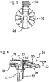
- a proximal area of the second cannula section 12 extends from a plate-shaped handle as a support element 16, which extends transversely or perpendicularly to the longitudinal axis of the second cannula section 12, as a comparison of FIGS 3 and 4 clarified.
- the proximal end of the first cannula section 10 is angled outwards or has a corresponding angled section 18.
- an actuating element designed as a lever 20 emanates from this and is supported via a projection 22 on a ramp-shaped section 26 of the handle or supporting element 16, so that the actuating element 20 designed as a lever can consequently be rotated about the projection 22, which is also referred to as knobs .
- the plate or plate-shaped handle in the region of the ramp-shaped sections 26 is cut out in such a way that, in accordance with the direction of the arrow 14, the first cannula section 10 can be adjusted to the supporting element 16 and thus the second cannula section 12 to such an extent that the first cannula section 10 can be released, that is to say pulled off is made possible by the second cannula section 12.
- the support element 16 has a recess 28 for inserting the catheter into the cannula.
- the lever 20 is locked so that there is no relative displacement of the first and second cannula sections 10, 12 when the cannula is set.
- the cannula-side region of the lever 20 underpins a web or projection 21 of the handle or support element 16, such as that Fig. 4 clarified.
- the lever 20 In order to be able to detach from the catheter (not shown), that is to be able to carry out the axial and radial adjustment of the first and second cannula sections 10, 12, the lever 20 must first be adjusted in the direction of arrow 23 to such an extent that the lever 20 is in engagement with it the projection or web 21 arrives. The lever 20 can then be pivoted about the projection 28 on the ramp-shaped section 26 of the handle or support element 16 by introducing a force in the direction of the arrow 24.
- the outer or first cannula section 10 is first displaced in the direction of the longitudinal axis of the cannula relative to the second cannula section 12, which is then pulled radially away from the second cannula section 12 when further force is applied is, so that according to the outline of the Fig. 2 the first cannula section 10 is withdrawn from the second cannula section 12 transversely to the longitudinal direction of the cannula. This becomes noticeable when the lever 24 is actuated, since when the clamping between the first and second cannula sections 10, 12 is overcome, the first cannula section 10 can be easily pulled off the side from the second cannula section 12.
- the actuating elements by means of which the first and second cannula sections 10, 12 can first be adjusted axially and then radially to one another in order to enable the first cannula section to be pulled off the second cannula section, can also be structurally solved in such a way that when force is applied from the distal region the cannula away the corresponding sequence of movements takes place.
- a safety mechanism in the distal region of the cannula is actuated at the same time, as a result of which a protective element 30, in particular tongue-shaped or channel-shaped, relative to the first cannula section 10 in the direction of the tip or puncture tip 32 of the first cannula section 10 is adjusted so that it is covered and thus a risk of injury is excluded.
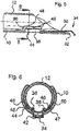
- the protective element 30 is angled distally (area 34), so that when the area 34 protrudes beyond the puncture tip 32, the puncture tip 32 is adequately covered, as shown in the sectional view according to FIG Fig. 5 clarified.
- FIG 5 to 8 following construction chosen.
- the protective element 30, which has a tongue or channel geometry and should lie flat against the inside of the first cannula section 10, has a rectangular cut-out which extends in the longitudinal direction of the protective element 30, the longitudinal edges of which are captured by bent-over sections of the first cannula section 10, so that fixing of the tongue-shaped or leaf-shaped protective element 30 with simultaneous relative displacement to the first cannula section 10 is made possible.
- the slot in the tongue-shaped protective element 30 is longer than the sections bent out of the first cannula section 10, which are shown in FIG Fig. 6 are identified by the reference symbols 36, 38.
- the first cannula section 10 is slotted (reference numeral 40), in order to then flare the sections 36, 38 and thus lie against the longitudinal edges of the longitudinal slot 42 of the tongue-shaped protective element. This results in a cutout 39 in the first cannula section 40, that of the sections 36, 38 is limited like that Fig. 8 clarified. In the Fig. 8 the protective element 30 is not shown.
- Wing-like sections 44, 46 extend from the side edges of the protective element 30, the longitudinal edges 48, 50 of the second cannula section 12 resting in sections on their longitudinal edges 45, 47. This ensures that the second cannula section 12 cannot be pressed into the interior of the first cannula section 10 in an uncontrolled manner. Furthermore, it follows from the Fig. 5 that the second cannula section 12 in the area of the wing-like sections 44, 46 each has a step 40 which bears against the wing-like sections 44, 46. This is illustrated by the graphical representation of the Fig. 5 clearly without the need for further explanations.
- the protective element 30 is pushed over the puncture tip 32 during the adjustment of the first cannula section 10 due to the contact of the steps 60 of the second cannula section 12 with the wing-like sections 44, 46.
- the length of the slot 42 and the wing-like sections 36, 38 as well as the lever 20 and the support 26 are matched to one another such that the first cannula section 10 is then pulled off the second cannula section 12, the distally angled section 34 of the protective element 30 being the tip 32 covers how this covers the Fig. 5 clarified.
- the 9 to 11 is a further embodiment of a the basic structure of the 1 to 4 described cannula to remove, but in relation to the protective element of the 5 to 8 differs.
- the protective element 30 has been designated as tongue-like or shell-shaped, the sectional view according to FIG Fig. 10 that, according to the second embodiment, a protective element 130 is preferably in contact with the inner surface of the first cannula section 10 over a larger arc than the protective element 30.
- the first cannula section 10 has elongated holes 52, 54 in which protrude laterally Protrusions 56, 58 of the protective element 130 engage, whereby a Relative displacement between the protective element 130 and the first cannula section 10 is made possible in the following manner.
- the protective element 130 has in its respective longitudinal side edge area a step 60 against which the distal longitudinal edge sections 62 of the second cannula section 12 come to rest.
- the step 60 is delimited proximally by a section 64 running parallel to the longitudinal axis of the second cannula section 12, on which the second cannula section 12 rests with its respective longitudinal edge 44, 46.
- This construction ensures that the second cannula section 12 cannot be pushed into the first cannula section 10 to an undesired extent.
- the protective element 130 has a tongue-shaped section 66 in the proximal region, through which the protective element 130 experiences a force deflection in the direction of the distal region 68, as is indicated by the arrow F.
- the protective element 130 is tilted in the direction of the puncture tip 32 about the projections 56, 58 acting as axes of rotation.
- a construction in this regard should be selected if the protective element 130 is made of metal.
- the protective element 130 is a plastic element, then it engages with the puncture tip 32 when the protective element 130 sweeps over the puncture tip 32 with its distal end. This takes place in accordance with the explanations given above by the axial relative movement between the first cannula section 10 and the second cannula section 12 when the lever 20 is actuated in the direction of the arrow 24, that is to say when a force is applied in the direction of the distal region of the cannula.
- the protective element 130 is prevented from moving when the first cannula section 10 is withdrawn, so that the protective element 130 is pushed over the puncture tip 32 and can latch with it .
- the distal area of the protective element 130 can be angled, as is the case in connection with the Fig. 5 has been clarified.
- the tongue or spring element 66 is mentioned required when the protective element 130 consists of a sheet metal material.
- the protective element 130 should have a recess 70 in its distal region, into which the tip 32 can snap, so that an uncontrolled release of the protective element 130 is excluded from the tip 32. In principle, this should be based on the Fig. 12 be made clear. It can be seen that the protective cap is adjusted in relation to the first cannula section 10 such that the opening 70 is penetrated by the puncture tip 32, so that the protective element 130 is locked.
- the wrap angle increasing from proximally in the direction of the distal region, that is to say in the direction of the protective element 30, 130, in the proximal region the wrap angle can be less than 180 °, that is, on average the radian is smaller than ⁇ .
- the tension in the distal region, in which the first section 10 wraps around the second section 12 preferably at an angle of 245 ° to 310 °, ensures that the first and second cannula sections 10, 12 do not come loose in an uncontrolled manner. rather, a pull-off is possible solely through the constructive solution according to the invention.
- FIG. 13 shows a side view of a cannula 100 with the first or outer cannula section 10 and the inner or second cannula section 12, the first cannula section 10 wrapping the second cannula section 12 more tightly in the distal region, that is to say in the region of the tip 32, than in the proximal region. that is, in the area of mechanics by means of which the first and second cannula sections 10, 12 are axially displaced relative to one another and then the first cannula section 10 is withdrawn radially from the second cannula section 12.
- the wrap angle In the distal area the wrap angle can be in the range between 240 ° and 310 °, whereas in the proximal area the wrap angle can be in the range between 180 ° and 120 ° can lie, just to give numbers as an example. From the outline of the Fig. 13 one also recognizes the handle that performs the function of the support element 16 for the lever 20. It should be mentioned that in Fig. 13 the change in the wrap angle is exaggerated.
- the first cannula section 10 is weakened in the area opposite the opening.
- Such a weakening of the material should not be provided in the area of the tip 36. This should preferably start at a distance of 2 cm to 3 cm from the tip 32. This weakening of material has the effect that the withdrawal of the first cannula section 10 from the second cannula section 12 is facilitated.
- a corresponding weakening of material is to be carried out in the case of a cannula 110 in accordance with FIG Fig. 14 be made clear in principle. From the rear view in the Fig. 14 it can be seen that the first cannula section 10 is materially weakened diametrically opposite to its longitudinal slot, the weakening beginning at a distance from the cannula or puncture tip 32.
- This detachment of the first cannula section 10 from the second cannula section 12 can additionally be facilitated in that, starting from the proximal area, starting from the side opposite the opening of the first cannula section 10, that is to say in the area of the lever 20, a longitudinal slit having a length of 2 can have cm to 3 cm.
- the first cannula section 10 is then angled adjacent to the slot, that is to say it has tabs bent at right angles in order to connect an actuating element such as a lever to each of them, i. h, each tab has a corresponding lever. If the required longitudinal relative movement has taken place between the first and second cannula sections 10, 12, so that the protective element 30, 130 covers the tip 32, the handles can be moved towards one another, making it easier to pull off.
- a cannula 120 having a proximal slot is that Fig. 15 refer to.
- Fig. 15 which shows a side view of the cannula 120, it can be seen that the first or outer cannula section 10 receives the inner or second cannula section 12 with a constant wrap angle, without thereby restricting the invention.
- a construction results in relation to the actuating element, such as this in principle 16 and 17 can be seen.
- a handle serving as a support element extends, which has a construction like that 3 and 4 can have. Due to the two sections of the first cannula section 10 separated by the slot, two lever elements 25, 27 can be locked and supported on the support element in the manner described above, the lever elements 25, 27 in the use position of the cannula as shown in FIG Fig. 16 are spaced from each other.
- a force must be exerted on the lever elements 25, 27 in order to axially shift the first to the second cannula section 10, 12 in the direction of the arrow 24. If the outer cannula section 10 is to be pulled off the second cannula section 12, the lever elements 25, 27 are pressed together ( Fig. 17 ), causing the first cannula section 10 to expand in accordance with the width of the slot. This makes it easier for the first cannula section 10 to be pulled off the second cannula section 12.
- the lever elements 25, 27 can be supported and rotated via projections 29, 31.
- Corresponding cannulas are slotted along their length, i. that is, they form a cannula shell that extends through an angle of 200 ° to 270 °.
- the sleeve body or the shell basically also have the geometry of a section of a circular arc in section.
- the exemplary embodiments of protective elements described below are not limited to corresponding channel cannulas, but can also be used with split cannulas which correspond to the exemplary embodiment of FIG 1 to 17 consist of two interlocking sections of circular arc shape. It is also possible to use split cannulas which are closed in one piece and all around in the initial state and which are separated after a catheter has been inserted.
- the distal section of a cannula 200 is shown, which, in accordance with the explanations given above, is designed as a longitudinally cut sleeve body.
- the cannula 200 has a puncture tip 232 in the distal region.
- a catheter 202 is received in a guided manner, which can be displaced in the longitudinal direction of the cannula 200 in order, for. B. to be inserted into a body cavity.
- a protective element 230 which can be displaced in the longitudinal direction of the cannula 200 and is used is used extends in sections along the inside of the cannula body and has laterally projecting projections 232 which engage in longitudinal slots 234 of the cannula body. This results in an axial guidance of the protective element 230. If only one slot 234 is shown in the figures, a corresponding slot runs diametrically opposite, into which a section of the protective element 230 also engages.
- the protective element 230 has a projection 236, which can be referred to as a driver and projects into the cannula interior, through which the protective element 230 then extends in the direction of the distal end of the cannula 200, that is, the puncture tip 232, and is pushed in the direction of the cannula tip when the catheter 202 comes to rest on the projection 236.
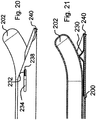
- the protective element 230 is carried along by the catheter 202 until the protrusion 232 bears against the distal boundary 238 of the slot 234, as that Fig. 20 clarified.
- a hook-shaped area 140 in the distal end of the protective element 230 can reach behind the puncture tip 232 and lock it with it, as is evident from FIGS 20 and 21 results.
- the protective element 230 is thus fixed by the protrusion 232 resting against the boundary of the slot 234 and the engagement of the puncture tip 232 by the hook-shaped distal section 240, so that longitudinal displacement is no longer possible.
- the puncture tip 232 is thus permanently covered by the protective element 230, ie its distal area, with the result that there is no risk of injury when the cannula 200 is pulled out and the catheter 202 is released.
- a fourth embodiment of a protective element 330 is that 22 to 27 refer to.
- the protective element 330 is explained again with the aid of a cannula, which consists of a longitudinally cut sleeve-shaped body, so that the same reference numerals as in connection with FIGS 18 to 21 be used.
- the protective element 330 is not displaceable overall longitudinally within the cannula 200, rather, it is firmly connected to the cannula 200 in a proximal region 332, as can be seen in principle from FIG Fig. 23 should result.
- the connection between the protective element 330 and the cannula 200 can be carried out by welding, gluing, riveting or in any other suitable way, medical considerations being taken into account.
- the protective element 330 has a prestressed section 334 which is bent in the direction of the central axis of the cannula 200, the height of the curved section 334 being such that when the catheter 202 is displaced, the latter is detected and pressed in the direction of the inside 336 of the cannula 200 ,
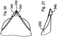
- the protective element 330 which is strip-shaped or tongue-shaped in plan view, is formed in its distal region 338 in such a way that a triangular geometry results in plan view, the edges 340, 342 being bent outwards and thus forming a pocket-shaped receptacle for the puncture tip 332, as is the case self-explanatory from the 26 and 27 results.
- Fig. 23 The starting position that the Fig. 23 is in again Fig. 24 shown in plan view of the cannula 200.
- Fig. 25 the protective element 330 is shown in the active position from the underside. Catheter 202 is not shown.
- a particularly noteworthy embodiment of a fifth embodiment of a protective element 430 is that 28 to 33
- the protective element 430 corresponds to the protective element 330 with regard to the fastening and the course.
- the protective element 430 is connected in its proximal area 432 to the inside 436 of a cannula 400 which is also single-shell in the exemplary embodiment and which differs from the cannula 200 in that the puncture tip 432 is bent inward, as the drawings show.
- the protective element 430 which likewise has an arcuate section in the non-activated state, has an opening 440 in its distal region 438, which is penetrated by the puncture tip 432 when the protective element 430 is activated, as can be seen in particular from FIGS Fig. 31 . 32 and 33 results.
- the arcuate section 434 runs in front of the distal region of the catheter 202, as the sectional illustration of FIG Fig. 29 clarified.
- a side view of the arrangement is the Fig. 28 refer to.
- the activated state i.e. in the state in which the Catheter 202 has pressed the arcuate section 434 to the required extent in the direction of the inner surface 436 of the cannula 400 so that the puncture tip 432 passes through the hole 440 in the distal region 430 of the protective element Fig. 31 and 32 refer to.
- covering is also to be clarified on the basis of this representation. Covering does not necessarily mean that the puncture tip 432 is covered immediately. Rather, the area of the puncture tip 432 is surrounded by the protective element 430, ie its distal area 430, to such an extent that, during normal handling of the cannula 400, contact with the cannula tip 432 cannot occur per se.
- a sixth embodiment of a protective element 530 results from FIGS 34 and 35 .
- a pivotable protective element such as protective element 530
- the protective element 530 can be pivoted by means of a connection and hinge element, not shown, via which the protective element 530 is connected to the cannula 200, specifically when the catheter 202 is moved in the direction of the puncture tip 232, as can be seen from a comparison of FIGS 34 and 35 results.
- the protective element 530 can be biased in such a way that when the protective element 530 covers the puncture tip 232 with its distal end 538, it remains in this position.
- protective elements by means of which a tip of a cannula is secured in such a way that an injury to users or patients is basically excluded, are 36 to 42 refer to.
- the protective elements are used in connection with cannulas that are designed with two shells, that is to say they have a structural design, as is shown in FIG 1 to 17 has been described. Reference is expressly made to the statements in this regard, so that the same reference symbols are used in principle for the same elements in order to avoid repetitions.
- the 36 to 38 a cannula 600 can be removed, which corresponds to the 1 and 2 consists of a first and second section 10, 12, wherein the first and second cannula section 10, 12 can have a circular arc geometry in section.
- the arc length of the first or outer cannula section 10 and that of the second or inner cannula section 12 being designed such that, in accordance with the teaching according to the invention, the sections can be pulled off, that is to say that the sections are radial to one another, that is are pulled apart transversely to the longitudinal axis of the cannula 600, so that they are separated from one another and thus a catheter penetrated by the cannula 600 is exposed.
- the catheter is according to the embodiments of the 18 to 35 identified by reference numeral 202.
- the first cannula section 10 is connected to the lever 20 which is supported on the section 26 of the handle 16 which is connected to the inner or second cannula section 12.
- Fig. 36 the cannula 600 is shown with the catheter 202 located therein and a non-activated protective element 630.
- the protective element 630 is in the exemplary embodiment of FIG 36 to 38 formed as a bowl-shaped body, which at least in sections bears prestressed on the inner wall of the first cannula section 10, so that there is a fixation provided that no longitudinal forces act on the protective element 630.
- the inner cross-section of the first cannula section 10 is not noticeably reduced by the protective element 630, so that problem-free axial adjustment of the catheter 220 is still possible.
- the protective element 630 is displaced in the direction of the puncture tip 632 to such an extent that it is covered by the distal region 638 of the protective element 630, as can be seen from the illustration of FIG Fig. 37 results.
- the protective element snaps into place
- the protective element 630 has, at least in its proximal area, preferably at least over half its length, a circular arc geometry in section, the arc length being more than ⁇ , as is also evident from the sectional view Fig. 38 results.
- the longitudinal edges 632, 634 of the protective element run parallel to the longitudinal axis of the cannula 600.
- the longitudinal edges 636, 637 of the inner lie on the longitudinal edges 632, 634 of the protective element 630 or second cannula section 12.
- the protective element 630 has a projection 640 running in the direction of the cannula wall at a distance from its distal end.
- the projection 640 can be formed by two wings 642, 644.
- corresponding incisions are made in the protective element 630, in order to then bend the wings 642, 644 outwards.
- the protective element 630 is moved in the direction of the puncture tip 632 when the lever 20 is pivoted counterclockwise in the drawing.
- the first cannula section 10 is axially adjusted to the left with respect to the second cannula section 12, that is to say it is apparently shortened.
- the protective element 630 is displaced along the inside of the first cannula section 10 in the direction of the puncture tip 632, since the protective element 630 is fixed by the second cannula section.
- the second cannula section 12 interacts positively with the protective element 630.
- the opening 646 is located diametrically to the longitudinal slot of the first cannula section 10, which, as mentioned, is also to be referred to as a longitudinally slotted sleeve body or a longitudinally slotted sleeve.
- a step of the second cannula section 612 engages in a section of the protective element 630, which is curved in section, without this being illustrated in the drawing.
- a protective element 730 is the Fig. 39 and 40 refer to.
- the protective element 730 differs from that of 36 to 38 solely in relation to the design of the distal region 738. Otherwise, the protective element 730 likewise has a shell-shaped body which extends over an arc of more than 180 ° and is quasi spring-loaded fixed in the first cannula section 710 and a projection 740 with wings 742 , 744, which engage in the through openings 746 of the first cannula section 10 when the protective element 730 is activated, such as Fig. 40 clarified.
- the protective element 630 or 730 is held by the second cannula section 12 when the first cannula section 10 is axially displaced relative to the second cannula section 12 in order to enable a longitudinal displacement along the first cannula section 10 to cover the cannula tip 632, 732 41 and 42 cannula 800 to be removed, the structure of which corresponds to that of the previously described cannula 600, 700 and thus the cannula 1 to 17 corresponds, a displacement of the protective element 830 by means of the catheter 202 enables, as in connection with the 18 to 21 has been explained without, however, the protective element 830 having to be guided in slots which are present in the cannula wall.
- the protective element 830 has a projection 836 projecting into the interior of the cannula 800, by means of which the protective element 830 is displaced in the direction of the puncture tip 832 when the catheter 202 is displaced axially in the cannula 800 in its direction. Since, in accordance with the explanations given above, the protective element 830 has a projection 640 formed by bent cutouts, which of course can also be constructed differently, further axial adjustment of the protective element 830 is precluded when the projection 840 enters the opening in the cannula 800 846 engages and locks in place, as the Fig. 42 can be seen. When the catheter 202 is further adjusted, it is deflected by the projection 836 in order to reach the desired area of a body. In this position, the second cannula section 12 must of course not hinder the deflection of the catheter 202. In the locked area of the protective element 836, the second cannula section 812 is no longer located above the projection 836.
- the protective element 830 has on the end face, that is to say in its distal region, a geometry which is wedge-shaped in section and corresponds to that of the cannula 800 in its distal region. This also ensures that an injury to the front edge of the cannula is excluded. Corresponding geometries can also have the further protective elements explained above.
- first or outer cannula section 10 or the outer shell is adjusted axially to the second or inner cannula section 12 or the inner shell by adjusting the lever 20
- the lever 20 there is of course also the possibility that of the second cannula section 12 a lever goes out, which can be supported on a section or a handle of the first cannula section and can be pivoted to the latter. In this case, the lever would not be moved towards the distal end of the cannula, but rather away from it.
- the respective protective element 630, 730, 830 has been described in connection with a double-shelled cannula 600, 700, 800, the guidance and adjustment of the respective protective element is also possible with a single-shelled cannula - not part of the subject matter of the invention - if that Protective element is not only biased in the direction of the inner wall of the shell, but an additional axial guidance is provided. This can be achieved in that a protrusion protrudes from the bottom of the bowl-shaped body, which protrudes into a recess of the protective element running in the axial direction or vice versa.
Landscapes
- Health & Medical Sciences (AREA)
- Life Sciences & Earth Sciences (AREA)
- Biophysics (AREA)
- Pulmonology (AREA)
- Engineering & Computer Science (AREA)
- Anesthesiology (AREA)
- Biomedical Technology (AREA)
- Heart & Thoracic Surgery (AREA)
- Hematology (AREA)
- Animal Behavior & Ethology (AREA)
- General Health & Medical Sciences (AREA)
- Public Health (AREA)
- Veterinary Medicine (AREA)
- Infusion, Injection, And Reservoir Apparatuses (AREA)
Description
- Die Erfindung bezieht sich auf eine Kanüle, insbesondere suprapubische Kanüle zum Einführen eines Katheters in einen Körperhohlraum, mit einem ersten Kanülenabschnitt in Form eines längsgeschnittenen ersten Hülsenkörpers, insbesondere mit im Schnitt eines Kreisbogens oder einer kreisbogenförmigen Geometrie, und einem beim Einführen eines Katheters mit diesem verbundenen zweiten Kanülenabschnitt in Form eines längsgeschnittenen zweiten Hülsenkörpers, insbesondere mit im Schnitt einer Kreisbogen-Geometrie oder einer kreisbogenförmigen Geometrie, wobei einer der Kanülenabschnitte im distalen Ende eine Punktionsspitze aufweist.
- Bei z. B. einer Katheterdrainage der Harnblase wird eine Kanüle oberhalb des Schambeins senkrecht zur Bauchdecke bis in die Harnblase gesetzt, um sodann durch die Kanüle einen Katheter einzuführen. Anschließend wird die Kanüle herausgezogen. Da sich diese jedoch nicht über den Ansatz des Katheters ziehen lässt, nimmt man spaltbare Kanülen. Eine solche ist z. B. der
DE 42 00 255 A1 zu entnehmen. Die Kanüle weist zwei diametral zueinander verlaufende Sollbruchlinien auf, wobei jede Hälfte der Kanüle einen Griff aufweist, um diese in entgegengesetzte Richtungen zu ziehen, wodurch sich die Kanüle in ihrer Längsrichtung trennt. Zum Trennen der Kanüle bedarf es erheblicher Kraft, so dass für den Anwender ein Verletzungsrisiko besteht. Auch weisen die Ränder scharfe Grate auf, die ein Verletzungsrisiko hervorrufen. Gleiches gilt in Bezug auf die Punktionsspitze, die bei unachtsamer Handhabung der Kanüle zu Verletzungen führen kann. - Eine Kanüle der eingangs genannten Art ist der
DE 33 47 150 C1 zu entnehmen. Die Kanüle besteht aus zwei gegeneinander verdrehbaren hülsenartigen Kanülenabschnitten mit Längsschlitz, welche also im Schnitt eine Kreisbogen-Geometrie bzw. kreisbogenförmige Geometrie aufweisen. Die Kanülenabschnitte werden zum Entfernen des Katheters derart zueinander ausgerichtet, dass die Längsschlitze zueinander fluchten. Da die Kanülenabschnitte unter hoher Spannung stehen, um insbesondere gegeneinander abgedichtet zu sein, müssen ggfs. hohe Drehmomente aufgebracht werden, um die Kanülenabschnitte gegeneinander zu verdrehen. Hierdurch bedingt kann eine unkontrollierte Bewegung mit der Folge auftreten, dass der Patient oder der Nutzer durch die Punktionsspitze verletzt wird. - Die
DE 10 2011 009 482 A1 bezieht auf eine Sicherheitskanüle, die aus einer äußeren und einer inneren längsgeschnittenen Hülse besteht, wobei die innere Hülse eine Punktionsspitze aufweist. Um zum Beispiel einen innerhalb der Innenhülse verlaufenden Katheterschlauch zu entfernen, werden die Längsschlitze der inneren und äußeren Hülse fluchtend zueinander ausgerichtet. Die Punktionsspitze verläuft innerhalb der äußeren Hülse, so dass eine Verletzungsgefahr vermieden werden kann. Ferner ist vorgesehen, dass sowohl von der inneren als auch von der äußeren Hülse jeweils eine Handhabe ausgeht, die derart betätigt werden können, dass zunächst ein axiales Verschieben der Hülsen zueinander und sodann ein Drehen erfolgt. - Eine spaltbare Kanüle ist der
US 4 345 596 A1 zu entnehmen. Die Kanüle wird durch Rohrhälften gebildet, die mittels einer Verzahnung dichtend aneinander liegen. Im proximalen Bereich sind Handhaben vorgesehen, die in Längsrichtung verlaufende Schrägen aufweisen, um beim Längsverschieben der Handhaben die Kanülenhälften voneinander zu trennen. - Die
US 5 295 977 A1 bezieht sich auf einen Trokar, dessen Spitze über ein Schutzelement abdeckbar ist. - Siehe auch
US 3 610 239 A . - Der vorliegenden Erfindung liegt die Aufgabe zu Grunde, eine Kanüle der eingangs genannten Art so weiterzubilden, dass ein problemloses Trennen der Kanülenabschnitte ermöglicht wird. Nach einem weiteren Aspekt der Erfindung soll sichergestellt sein, dass das Risiko einer Verletzung durch die Punktionsspitze vermieden wird.
- Zur Lösung zumindest eines Aspekts der Erfindung ist vorgesehen, dass sich die miteinander verbundenen Kanülenabschnitte umschlingen, wobei der erste Kanülenabschnitt einen Umschlingungswinkel in Bezug auf den zweiten Kanülenabschnitt aufweist, der in einem senkrecht zur Längsachse des ersten Kanülenabschnitts verlaufenden Schnitt größer als 180° ist, und dass zum Lösen der Kanülenabschnitte voneinander einer der Kanülenabschnitte gegenüber dem anderen Kanülenabschnitt mittels zumindest eines von einem der Kanülenabschnitte ausgehenden und sich direkt oder indirekt an dem anderen Kanülenabschnitt abstützenden
- Betätigungselements bei Krafteinwirkung auf das Betätigungselement quer zur Längsachse der Kanüle abziehbar ist, wobei das Betätigungselement ein Hebelelement ist, das über einen von diesem abragenden Vorsprung an einem Abschnitt eines von dem anderen Kanülenabschnitt ausgehenden Abstützelements abstützbar ist. Abweichend von vorbekannten Kanülen, die aus zwei hülsenartigen Kanülenabschnitten mit Längsschlitz bestehen, werden nach der erfindungsgemäßen Lehre die ebenfalls hülsenartigen Kanülenabschnitte mit Längsschlitz der Kanüle gemäß Anspruch 1 quer zur Längsachse auseinander gezogen, wobei eine kontrollierte Krafteinwirkung zum Lösen bzw. Beabstanden der Kanülenabschnitte mittels eines Betätigungselementes erfolgt, das von einem Kanülenabschnitt ausgeht und sich direkt oder indirekt an dem anderen Kanülenabschnitt abstützt, um die Trennung durchzuführen.
- Insbesondere ist vorgesehen, dass bei Krafteinwirkung des Betätigungselementes in Längsrichtung der Kanüle, vorzugsweise in Richtung des distalen Bereichs der Kanüle, der Kanülenabschnitt, von dem das Betätigungselement ausgeht, zunächst in Längsrichtung der Kanüle entlang des anderen Kanülenabschnitts verschiebbar ist und dass sodann bei weiterer Krafteinwirkung der eine Kanülenabschnitt zumindest im proximalen Bereich von dem anderen Kanülenabschnitt lösbar ist.
- Das Betätigungselement ist ein Hebelelement, das über einen von diesem abragenden Vorsprung an einem insbesondere rampenförmigen Abschnitt des Abstützelements abstützbar ist.
- Dabei sollte insbesondere das Abstützelement ein sich quer zur Längsrichtung des zweiten Kanülenabschnitts erstreckendes plattenförmiges Element sein, das in Richtung des Lösens der Kanülenabschnitte voneinander den ersten Kanülenabschnitt in einem Abstand umgibt, der ein Lösen der Kanülenabschnitte ermöglicht.
- Nach einem eigenerfinderischen Vorschlag und zur Lösung eines weiteres Aspektes der Erfindung ist vorgesehen, dass von dem ersten Kanülenabschnitt einer Kanüle gemäß Anspruch 1 ein entlang dessen Innenseite verstellbares Schutzelement ausgeht, das in Nutzposition der Kanüle beabstandet zu der Punktionsspitze verläuft und nach Trennen der Kanülenabschnitte die Punktionsspitze abdeckt. Das Schutzelement ist derart zu dem die Punktionsspitze aufweisenden Kanülenabschnitt verschiebbar, dass dann, wenn der die Punktionsspitze aufweisende Kanülenabschnitt senkrecht zu dem zweiten Kanülenabschnitt verschoben wird, das Schutzelement in Richtung der Punktionsspitze zum Abdecken dieser verstellt wird.
- Dabei ist bevorzugterweise vorgesehen, dass das Schutzelement ein zungen- oder rinnenförmiges Element ist, in dessen Längsrichtung ein Schlitz verläuft, von dessen Längsrandseiten flügelartige Abschnitte ausgehen, dass von dem ersten Kanülenabschnitt nach innen umgebogene und den Schlitz durchsetzende und an dessen Längsrandabschnitten anliegende Halteabschnitte ausgehen, die in Längsrichtung des ersten Kanülenabschnitts eine Länge aufweisen, die kürzer als die Länge des Schlitzes ist, und dass in Nutzposition der Kanüle auf den Längsrändern der flügelartigen Abschnitte die Längsränder des zweiten Kanülenabschnitts bereichsweise aufliegen. Ferner weist der Kanülenabschnitt in seinem distalen Bereich eine stufenförmige Aussparung auf, die sich an den flügelartigen Abschnitten abstützt, um die gewünschte Relativbewegung zwischen dem Schutzelement und dem ersten Kanülenabschnitt zu ermöglichen mit der Folge, dass das Schutzelement über die Punktionsspitze hinausgeschoben wird. Das Abdecken der Punktionsspitze erfolgt über einen entsprechend abgewinkelten Abschnitt des distalen Endes des Schutzelementes. Es besteht jedoch auch die Möglichkeit, dass das Schutzelement in seinem distalen Bereich eine Aussparung aufweist, in die die nach innen gebogene Punktionsspitze zum Verrasten des Schutzelementes eindringt.
- Dadurch, dass die Längsränder des zweiten Kanülenabschnitts bereichs- bzw. abschnittsweise auf den Längsrändern der flügel artigen Abschnitte aufliegen, ist des Weiteren sichergestellt, dass ein unkontrolliertes Hineindrücken des zweiten Kanülenabschnitts in den ersten Kanülenabschnitt unterbunden wird.
- Um sicherzustellen, dass die flügelartigen Abschnitte ein Lösen der Kanülenabschnitte voneinander nicht behindern, ist vorgesehen, dass der zweite Kanülenabschnitt in Verschieberichtung der flügelartigen Abschnitte zumindest eine Aussparung aufweist, in die beim Lösen des ersten Kanülenabschnitts von dem zweiten Kanülenabschnitt die flügelartigen Abschnitte eingreifen.
- Nach einer alternativen Lösung zur Ausbildung des Schutzelementes wird vorgeschlagen, dass der erste Kanülenabschnitt in dessen Längsrichtung verlaufende Langlöcher aufweist, in die von dem Schutzelement ausgehende Vorsprünge eingreifen, dass der zweite Kanülenabschnitt mit dem Schutzelement derart wechselwirkt, dass bei Längsverschiebung des ersten Kanülenabschnitts zu dem zweiten Kanülenabschnitt das Schutzelement in Richtung der Punktionsspitze und zum Abdecken dieser verschiebbar ist.
- Um bei der diesbezüglichen Ausführungsform die Relativbewegung zwischen dem Schutzelement und dem die Punktionsspitze aufweisenden ersten Kanülenabschnitt sicherzustellen, um also das Schutzelement über die Punktionsspitze zu verschieben, ist insbesondere vorgesehen, dass das Schutzelement proximal einen stufenförmigen Abschnitt aufweist, an dem der distale Bereich des zweiten Kanülenabschnitts bei Verschieben des ersten Kanülenabschnitts zu dem zweiten Kanülenabschnitt anliegt.
- Das Schutzelement kann z. B. ein Kunststoffteil wie Spritzgussteil sein, aber auch aus Metall bestehen. Wird ein Kunststoffteil benutzt, so verhakt dieses mit der Punktionsspitze dann, wenn diese geringfügig in Richtung der Längsachse nach innen gebogen ist, so dass das Schutzelement bleibend die Punktionsspitze abdeckt. Hierzu ist vorzugsweise der distale Bereich des Schutzelementes U-förmig abgewinkelt, so dass die Punktionsspitze insbesondere zwischen freiem Seitenschenkel und Querschenkel des distalen Abschnitts des Schutzelementes fixiert wird.
- Wird ein Schutzelement aus einem gebogenen Metallstreifen benutzt, so sollte das Schutzelement in seinem distalen Bereich eine Aussparung aufweisen, in die bei abgedeckter Punktionsspitze diese eingreift. Auch kann der distale Bereich des aus Metall bestehenden Schutzelementes hakenförmig, also im Schnitt in etwa U-förmig gebogen sein, um sicherzustellen, dass die Spitze in diesem Bereich verbleibt und ein unkontrolliertes Lösen des Schutzelementes verhindert wird.
- Um bei einem Metallteil ein unkontrolliertes Lösen des Schutzelementes von der Punktionsspitze auszuschließen, um also den distalen Bereich des Schutzelements in Richtung der Kanülenspitze kraftzubeaufschlagen, ist vorgesehen, dass das Schutzelement in seinem proximalen Bereich ein sich an der Innenwandung des ersten Kanülenabschnitts abstützendes Zungenelement zur Krafteinleitung in den distalen Bereich des Schutzelements in Richtung der Innenseite des ersten Kanülenabschnitts aufweist.
- Eine Kanüle zum Einrühren eines Katheters in einen Körperhohlraum, wobei die Kanüle nach dem Ablegen des Katheters von dem Katheter getrennt werden soll, muss nicht zwingend zwei Kanülenabschnitte aufweisen, die eine zuvor beschriebene Gestaltung aufweisen, die auch als geschnittene Hülsenkörper bezeichnet werden können. Vielmehr kann eine Kanüle - nicht zum Gegenstand der Erfindung gehörend - benutzt werden, die einen einzigen hülsenförmigen längsgeschnittenen Körper aufweist, wobei die Hülse, die auch als Schale bezeichnet werden kann, im Schnitt einen Bogen zwischen 200° und 270° aufweisen sollte, wenn man von einem Querschnitt ausgeht, der einem Kreisbogen folgt.
- Auch für entsprechende einschalige Kanülen ist nach einem Aspekt der vorliegenden Lehre die Möglichkeit gegeben, dass die Punktionsspitze derart abgedeckt wird, dass eine Verletzungsgefahr unterbunden wird. Abdecken bedeutet dabei, dass die Punktionsspitze mit einem Schutz versehen ist, der es ermöglicht, dass die Punktionsspitze nicht freiliegt.
- Die Offenbarung bezieht sich daher auch auf eine Kanüle mit in dessen Längsrichtung verschiebbarem Katheter, insbesondere suprapubische Kanüle zum Einführen eines Katheters in einen Körperhohlraum, umfassend zumindest einen ersten Kanülenabschnitt, wie längsgeschnittenen Hülsenkörper, insbesondere mit im Schnitt eines Kreisbogens oder einer kreisbogenförmigen Geometrie, mit einem proximalen Ende und einem distalen Ende mit Punktionsspitze und zeichnet sich dadurch aus, dass von der Innenseite der Kanüle ein verstellbares Schutzelement ausgeht, das in Nutzposition der Kanüle beabstandet zu der Punktionsspitze verläuft und nach Verschieben des Katheters in Richtung der Punktionsspitze und/oder bei von dem ersten Kanülenabschnitt aufgenommenen zweiten Kanülenabschnitt mit im Schnitt eines Kreisbogens oder einer kreisbogenförmigen Geometrie und Längsverschiebung des ersten Kanülenabschnitts zu dem zweiten Kanülenabschnitt die Punktionsspitze von dem Schutzelement abgedeckt und/oder das Schutzelement von der Punktionsspitze bereichsweise durchsetzt ist.
- Insbesondere ist vorgesehen, dass das Schutzelement mit der Punktionsspitze und/oder in dem ersten Kanülenabschnitt verrastet.
- Insbesondere ist vorgesehen, dass das Schutzelement mit der Kanüle verbunden wie verschweißt, verklebt oder vernietet ist und bei fehlender Einwirkung des Katheters auf das Schutzelement einen innerhalb der Kanüle in Richtung der Kanülenlängsachse verlaufenden Bogenabschnitt aufweist, wobei distales Ende des Schutzelementes beabstandet zu der Punktionsspitze verläuft, und dass bei Verstellen des Katheters in Richtung der Punktionsspitze und Wechselwirken mit dem Schutzelement der gebogene Abschnitt in Richtung der Kanüleninnenseite gedrückt wird derart, dass das Schutzelement durch scheinbare Längenveränderung mit seinem distalen Ende mit der Punktionsspitze wechselwirkt.
- Insbesondere kann das Schutzelement in seinem vorzugsweise zungenförmig ausgebildeten distalen Bereich eine Öffnung aufweisen, in die bei in Richtung der Kanüleninnenseite gedrücktem Schutzelement die Punktionsspitze eingreift. Das Schutzelement kann in seinem distalen Bereich auch einen Geometrieverlauf wie den oder in etwa den des distalen Stirnrandes der Kanüle bzw. des ersten Kanülenabschnitts aufweisen.
- Es besteht jedoch auch die Möglichkeit, dass das Schutzelement in seinem distalen Bereich eine Aufnahme für die Punktionsspitze aufweist. Dabei kann die Aufnahme z. B. durch ein oder mehrere gebogene Randabschnitte des distalen Endes des Schutzelementes gebildet sein, so dass sich eine quasi taschenförmige Aufnahme für die insbesondere nach innen, also in Richtung Kanülenlängsachse gebogene Punktionsspitze ergibt.
- Nach einer weiteren Ausgestaltung der Offenbarung ist vorgesehen, dass das Schutzelement mit dem Hülsenkörper in seinem zum distalen Ende fernliegenden Bereich, also insbesondere im proximalen Bereich nicht fest verbunden ist, sondern insgesamt in Längsrichtung des Hülsenkörpers verschiebbar ist. Hierzu ist insbesondere vorgesehen, dass der Hülsenkörper in Längsrichtung verlaufende Schlitze aufweist, in die Abschnitte des Schutzelementes eingreifen. Zum Verstellen des Schutzelementes weist dieses einen ins Innere der Kanüle ragenden Abschnitt auf, der beim Verstellen des Katheters mitgenommen wird, so dass der distale Bereich des Schutzelementes in den Bereich der Punktionsspitze gelangt und diese abdeckt oder die Punktionsspitze in das Schutzelement eindringt, die eine Öffnung durchsetzen kann.
- Eine weitere Gestaltung eines Schutzelementes sieht vor, dass dieses schwenkbar mit der Kanüle verbunden ist derart, dass bei Verstellen des Katheters in Richtung der Punktionsspitze das Schutzelement in Richtung der Punktionsspitze derart verschwenkt wird, dass der distale Bereich des Schutzelementes die Punktionsspitze abdeckt oder diese das Schutzelement durchsetzt.
- Die Erfindung zeichnet sich nach einem selbständigen Lösungsvorschlag auch dadurch aus, dass das Schutzelement innerhalb des ersten Kanülenabschnitts an dessen Innnenseite zumindest bereichsweise anliegt und dass der erste Kanülenabschnitt in seinem dem Längsschlitz gegenüberliegenden Bereich eine Aufnahme wie Öffnung aufweist, in die ein von dem Schutzelement ausgehender Vorsprung bei die Punktionsspitze abdeckendem Schutzelement eingreift.
- Hierzu wird vorzugsweise vorgeschlagen, dass der in die Aufnahme einrastbare Vorsprung des Schutzelementes durch zwei quer zur Längsachse des Schutzelementes verlaufende aus dem Schutzelement gebogene flügelartige Abschnitte gebildet ist.
- Insbesondere ist vorgesehen, dass das Schutzelement vorgespannt zumindest bereichsweise an der Innenseite des ersten Kanülenabschnitts anliegt. Hierdurch ergibt sich der Vorteil, dass das Schutzelement den inneren Querschnitt des Kanülenabschnitts nicht wesentlich verringert, so dass weiterhin ein ungehindertes axiales Verschieben des Katheters möglich ist.
- Hervorzuheben ist des Weiteren, dass das Schutzelement mit einem im Schnitt kreisbogenförmigen oder einem Kreisbogen folgenden Abschnitt zumindest bereichsweise an der Innenseite anliegt, dass der Abschnitt parallel zur Längsachse des ersten Kanülenabschnitts verlaufende Längsränder aufweist und dass an den Längsrändern der von dem ersten Kanülenabschnitt aufgenommene zweite Kanülenabschnitt mit seinen Längsrändern zumindest bereichsweise anliegt. Durch diese konstruktiven Maßnahmen ist eine sichere Führung des Schutzelementes in Längsrichtung der Kanüle sichergestellt. Gleichzeitig ergibt sich eine Unverdrehbarkeit.
- Unabhängig von der Art, wie das Schutzelement zur Erzielung der Relativbewegung zu der Kanüle bzw. zum ersten Kanülenabschnitt fixiert wird, ist vorgesehen, dass das Schutzelement zungen- oder rinnenförmig ausgebildet ist und außenseitig flächig oder im Wesentlichen flächig an der Innenseite des ersten Kanülenabschnitts bzw. des Hülsenkörpers anliegt.
- Im proximalen Bereich sollte der erste Kanülenabschnitt senkrecht zur Längsachse zumindest abschnittsweise ein Bogenmaß B1 mit B1 > π und der zweite Kanülenabschnitt ein Bogenmaß B2 mit B1 + B2 > 2 π aufweisen.
- Mit anderen Worten ist in einem senkrecht zur Längsachse des ersten Abschnitts verlaufenden Schnitt die Bogenlänge des ersten Kanülenabschnitts größer als R1 π, wobei R1 tatsächlicher bzw. fiktiver Radius des ersten Kanülenabschnitts im Schnittbereich ist. Der Umschlingungswinkel zwischen den Längsrändern des ersten Kanülenabschnitts beträgt somit mehr als 180°, liegt insbesondere zwischen 245° und 310°. Der Umschlingungswinkel kann vom distalen Bereich bis zum proximalen Bereich hin abnehmen.
- Dabei ist insbesondere vorgesehen, dass senkrecht zur Längsachse der Kanüle der erste Kanülenabschnitt im proximalen Bereich ein Bogenmaß B3 und der zweite Kanülenabschnitt ein Bogenmaß B4 mit B3 < π und B3 + B4 > 2π aufweisen.
- Insbesondere ist vorgesehen, dass der erste und der zweite Kanülenabschnitt im distalen Bereich, insbesondere bis in den Bereich des Schutzelementes, jeweils ein Bogenmaß B5 mit B5 > π, insbesondere 1,2 π < B5 ≤ 1,75 π aufweist.
- Um das Abziehen des ersten oder äußeren Kanülenabschnitts von dem zweiten oder inneren Kanülenabschnitt zu erleichtern, hat es sich als vorteilhaft erwiesen, dass zumindest einer der Kanülenabschnitte, vorzugsweise der erste Kanülenabschnitt auf der zu seiner Längsöffnung gegenüberliegenden Seite durch z. B. Prägen materialgeschwächt ist.
- Alternativ oder ergänzend kann vorgesehen sein, dass vom proximalen Rand einer der Kanülenabschnitte wie des ersten Kanülenabschnitts auf der zu dessen Längsöffnung gegenüberliegender Seite ein Schlitz ausgeht und dass von jedem der zu dem Schlitz benachbarten Bereiche des Kanülenabschnitts ein Betätigungselement ausgeht.
- Zum Abziehen des äußeren oder ersten Kanülenabschnitts von dem inneren oder zweiten Kanülenabschnitt ist es sodann nur erforderlich, dass nach der Kraftbeaufschlagung der Betätigungselemente in Richtung der Punktionsspitze, wodurch die Relativverschiebung zwischen dem Schutzelement und dem ersten Kanülenabschnitt erfolgt, die Betätigungselemente aufeinanderzu bewegt werden, so dass ein Spreizen der Längsränder des ersten Kanülenabschnitts im proximalen Bereich mit der Folge gegeben ist, dass ein problemloses Abziehen des ersten Kanülenabschnitts von dem zweiten Kanülenabschnitt ohne größere Krafteinleitung möglich ist.
- Bestehen vorzugsweise sowohl der erste als auch der zweite Kanülenabschnitt aus Metall, wobei der erste und zweite Kanülenabschnitt durch Rollen eines Blechstreifens hergestellt sein kann, so besteht auch die Möglichkeit, dass der zweite Kanülenabschnitt aus Kunststoff besteht und z. B. ein Spritzgussteil ist.
- Weitere Einzelheiten, Vorteile und Merkmale der Erfindung ergeben sich nicht nur aus den Ansprüchen, den diesen zu entnehmenden Merkmalen - für sich und/oder in Kombination -, sondern auch aus der nachfolgenden Beschreibung von der Zeichnung zu entnehmenden bevorzugten Ausführungsbeispielen.
- Es zeigen:
- Fig. 1
- einen Schnitt durch eine Kanüle, die einen ersten und einen zweiten Kanülenabschnitt aufweist, die ineinandergreifen,
- Fig. 2
- die Kanüle nach
Fig. 1 , bei der der erste Kanülenabschnitt von dem zweiten Kanülenabschnitt abgezogen wird, - Fig. 3
- eine Draufsicht auf ein Abstützelement und ein Betätigungselement, die vom proximalen Bereich der Kanülenabschnitte ausgehen,
- Fig. 4
- einen Schnitt durch die Darstellung gemäß
Fig. 3 und im Ausschnitt, - Fig. 5
- einen Schnitt durch die Kanüle gemäß
Fig. 1 in deren distalen Bereich mit einer ersten Ausführungsform eines Schutzelementes, - Fig. 6
- einen Schnitt entlang der Linie B-B in
Fig. 5 , - Fig. 7
- einen Ausschnitt des zweiten Kanülenabschnitts,
- Fig. 8
- einen Ausschnitt der Kanüle im distalen Bereich,
- Fig. 9
- einen Ausschnitt der Kanüle im distalen Bereich mit einer zweiten Ausführungsform eines Schutzelementes,
- Fig. 10
- einen Schnitt durch die Kanüle gemäß
Fig. 9 im Bereich des Schutzelementes, - Fig. 11
- eine Schnittdarstellung der Kanüle gemäß
Fig. 9 und 10 im distalen Bereich, - Fig. 12
- eine der
Fig. 11 entsprechende Darstellung, bei der das Schutzelement verriegelt ist, - Fig. 13
- eine Seitenansicht einer Kanüle,
- Fig. 14
- eine Rückansicht einer weiteren Ausführungsform einer Kanüle,
- Fig. 15
- eine weitere Kanüle in Seitenansicht,
- Fig. 16
- eine weitere Ausführungsform eines Betätigungselements mit Griff in Draufsicht und
- Fig. 17
- das Betätigungselement mit Griff gemäß
Fig. 16 in aktivierter Position, - Fig. 18
- eine Kanüle mit einer dritten Ausführungsform eines Schutzelementes in Seitenansicht,
- Fig. 19
- die Darstellung gemäß
Fig. 18 im Schnitt, - Fig. 20
- das den
Fig. 18 und 19 zu entnehmende Schutzelement in aktivierter Stellung und in Seitenansicht, - Fig. 21
- die Darstellung gemäß
Fig. 20 in Schnittdarstellung, - Fig. 22
- in Seitenansicht eine Kanüle mit einer vierten Ausführungsform eines Schutzelementes,
- Fig. 23
- die Darstellung gemäß
Fig. 22 in Schnittdarstellung, - Fig. 24
- das Schutzelement gemäß der
Fig. 22 und 23 mit Kanüle und Katheter im Ausschnitt und Draufsicht, - Fig. 25
- das Schutzelement der
Fig. 22 bis 24 in aktivierter Stellung, - Fig. 26
- das aktivierte Schutzelement gemäß
Fig. 25 mit Punktionsspitze, - Fig. 27
- eine Seitenansicht des aktivierten Schutzelementes gemäß der
Fig. 22 bis 26 mit Punktionsspitze, - Fig. 28
- eine Seitenansicht einer Kanüle mit einer fünften Ausführungsform eines Schutzelementes,
- Fig. 29
- die Darstellung gemäß
Fig. 28 in Schnittdarstellung, - Fig. 30
- eine Unteransicht der Kanüle gemäß der
Fig. 28 und 29 mit aktiviertem Schutzelement, - Fig. 31
- die Kanüle der
Fig. 28 bis 30 mit aktiviertem Schutzelement, - Fig. 32
- die Darstellung gemäß
Fig. 31 in Schnittdarstellung, - Fig. 33
- eine vergrößerte Darstellung der Punktionsspitze der Kanüle gemäß der
Fig. 28 bis 32 mit aktiviertem Schutzelement, - Fig. 34
- eine Schnittdarstellung einer Kanüle mit einer sechsten Ausführungsform eines Schutzelementes in Ausgangslage,
- Fig. 35
- die Kanüle gemäß
Fig. 34 mit dem Schutzelement in aktivierter Stellung, - Fig. 36
- einen Schnitt durch eine Kanüle mit einer weiteren Ausführungsform eines Schutzelementes,
- Fig. 37
- die Kanüle gemäß
Fig. 36 mit aktiviertem Schutzelement, - Fig. 38
- einen Schnitt durch die Kanüle gemäß
Fig. 36 und37 , - Fig. 39
- einen Ausschnitt einer Kanüle mit einer achten Ausführungsform eines Schutzelementes,
- Fig. 40
- die Kanüle gemäß
Fig. 39 mit aktiviertem Schutzelement, - Fig. 41
- einen Ausschnitt einer Kanüle mit einer neunten Ausführungsform eines Schutzelementes und
- Fig. 42
- die Kanüle gemäß
Fig. 41 mit aktiviertem Schutzelement. - In den
Figuren 1 bis 17 , in denen grundsätzlich gleiche Elemente mit gleichen Bezugszeichen gekennzeichnet werden, sind zwei Ausführungsformen einer Kanüle dargestellt, die nach Legen eines Katheters von diesem entfernt werden kann, ohne dass die Kanüle über den Ansatz des Katheters geschoben werden muss. Hierzu besteht die Kanüle aus zwei Kanülenabschnitten, und zwar einem äußeren oder ersten Kanülenabschnitt 10 und einem zweiten oder inneren Kanülenabschnitt 12, wobei der erste Kanülenabschnitt 10 den zweiten Kanülenabschnitt 12 umfasst, wie sich aus einem Vergleich derFig. 1 und 2 ergibt. - Sowohl der erste, also äußere Kanülenabschnitt 10, als auch der zweite, also innere Kanülenabschnitt 12, weisen im Schnitt eine hülsenartige Geometrie mit Längsschlitz, also eine Bogen- bzw. bogenförmige Geometrie auf. Dabei kann jedoch der Umschlingungswinkel des ersten Abschnitts 10 vom distalen zum proximalen Bereich hin abnehmen. Der jeweilige Abschnitt 10, 12 kann auch als Hülsenkörper mit Längsschlitz oder als Schalenkörper bezeichnet werden.
- In der idealisierten Bogenform weist der Kanülenabschnitt 10 zumindest im proximalen Bereich der Kanüle ein Bogenmaß B1 mit B1 größer π auf, also einen Umschlingungswinkel in Bezug auf den zweiten Kanülenabschnitt 12, der größer als 180° ist, insbesondere im Bereich zwischen 245° und 305° liegt. Der innere Abschnitt 12 kann einen entsprechenden Öffnungswinkel aufweisen, also gleichfalls ein Bogenmaß größer π besitzen. Die Bogenlänge des ersten Abschnitts 10 ist somit größer π · R1 mit R1 tatsächlicher oder fiktiver Radius des ersten Kanülenabschnitts 10. Die Bogenlänge des zweiten Kanülenabschnitts 12 in einem senkrecht zur Längsahse der Kanüle verlaufenden Schnitt ist demzufolge gleichfalls größer π · R2 und mit R2 tatsächlich oder fiktiver Radius des zweiten Abschnitts 12.
- Werden nach dem Stand der Technik entsprechende schalen- oder rinnenförmige Abschnitte einer Kanüle zueinander verdreht, um den Innenraum der Kanüle frei zugänglich zu machen, um also über die zueinander ausgerichteten Schlitze der Abschnitte einen Katheter durchzuführen, ist erfindungsgemäß vorgesehen, dass der erste Kanülenabschnitt 10 zu dem zweiten Kanülenabschnitt 12 quer zur Längsrichtung der Kanüle auseinander gezogen werden, wie durch den Pfeil 14 angedeutet wird. Hierzu ist erfindungsgemäß vorgesehen, dass von proximalem Bereich des zweiten Kanülenabschnitts 12 ein insbesondere tellerförmig ausgebildeter Griff als Abstützelement 16 ausgeht, das sich quer bzw. senkrecht zur Längsachse des zweiten Kanülenabschnitts 12 erstreckt, wie ein Vergleich der
Fig. 3 und 4 verdeutlicht. Das proximale Ende des ersten Kanülenabschnitts 10 ist nach außen abgewinkelt oder weist einen entsprechenden abgewinkelten Abschnitt 18 auf. Von diesem geht ein als Hebel 20 ausgebildetes Betätigungselement aus, das über einen Vorsprung 22 auf einen rampenförmig ausgebildeten Abschnitt 26 des Griffs oder Abstützelementes 16 abgestützt ist, so dass infolgedessen das als Hebel ausgebildete Betätigungselement 20 um den auch als Noppen zu bezeichnenden Vorsprung 22 drehbar ist. Aus der Schnittdarstellung derFig. 4 ist des Weiteren erkennbar, dass der platten- oder tellerförmige Griff im Bereich der rampenförmigen Abschnitte 26 derart ausgeschnitten ist, dass entsprechend der Richtung des Pfeils 14 der erste Kanülenabschnitt 10 zu dem Abstützelement 16 und damit dem zweiten Kanülenabschnitt 12 in einem Umfang verstellbar ist, dass ein Lösen, also ein Abziehen des ersten Kanülenabschnitts 10 von dem zweiten Kanülenabschnitt 12 ermöglicht wird. Gegenüberliegend zu dem Hebel 20 weist das Abstützelement 16 eine Vertiefung 28 zum Einführen des Katheters in die Kanüle auf. - Damit eine Relativverschiebung des ersten und zweiten Kanülenabschnitts 10, 12 beim Setzen der Kanüle unterbleibt, wird der Hebel 20 verriegelt. Hierzu unterfasst der kanülenseitige Bereich des Hebels 20 einen Steg oder Vorsprung 21 des Griffs oder Abstützelements 16, wie die
Fig. 4 verdeutlicht. Um ein Lösen von dem nicht dargestellten Katheter vorzunehmen, also die axiale und radiale Verstellung des ersten und zweiten Kanülenabschnitts 10, 12 durchführen zu können, muss sodann zunächst der Hebel 20 in Pfeilrichtung 23 in einem Umfang verstellt werden, dass der Hebel 20 in Ausgriff mit dem Vorsprung bzw. Steg 21 gelangt. Sodann kann der Hebel 20 um den Vorsprung 28 auf dem rampenförmigen Abschnitt 26 des Griffs oder Abstützelementes 16 durch Einleitung einer Kraft in Richtung des Pfeils 24 verschwenkt werden. - Wirkt auf den Hebel 20 eine Kraft in Richtung des Pfeils 24, so wird zunächst der äußere oder erste Kanülenabschnitt 10 in Richtung der Längsachse der Kanüle relativ zu dem zweiten Kanülenabschnitt 12 verschoben, der sodann bei weiterer Krafteinleitung radial zu dem zweiten Kanülenabschnitt 12 von diesem weggezogen wird, so dass entsprechend der Prinzipdarstellung der
Fig. 2 der erste Kanülenabschnitt 10 von dem zweiten Kanülenabschnitt 12 quer zur Längsrichtung der Kanüle abgezogen wird. Dies wird beim Betätigen des Hebels 24 spürbar, da dann, wenn die Klemmung zwischen dem ersten und zweiten Kanülenabschnitt 10, 12 überwunden ist, ein leichtes seitliches Abziehen des ersten Kanülenabschnitts 10 von dem zweiten Kanülenabschnitt 12 ermöglicht wird. - Selbstverständlich können die Betätigungselemente, mittels derer der erste und zweite Kanülenabschnitt 10, 12 zunächst axial und sodann radial zueinander verstellbar sind, um ein Abziehen des ersten Kanülenabschnitts von dem zweiten Kanülenabschnitt zu ermöglichen, konstruktiv auch so gelöst werden, dass bei einer Krafteinwirkung vom distalen Bereich der Kanüle weg der entsprechende Bewegungsablauf erfolgt.
- Während der axialen Relativverstellung zwischen dem ersten und zweiten Abschnitt 10, 12 wird gleichzeitig ein Sicherheitsmechanismus im distalen Bereich der Kanüle betätigt, wodurch ein insbesondere zungen- oder rinnenförmiges Schutzelement 30 relativ zu dem ersten Kanülenabschnitt 10 in Richtung der Spitze bzw. Punktionsspitze 32 des ersten Kanülenabschnitts 10 verstellt wird, so dass diese abgedeckt wird und somit eine Verletzungsgefahr ausgeschlossen ist. Hierzu ist das Schutzelement 30 distal abgewinkelt (Bereich 34), so dass dann, wenn der Bereich 34 über der Punktionsspitze 32 vorsteht, die Punktionsspitze 32 hinreichend abgedeckt wird, wie die Schnittdarstellung gemäß
Fig. 5 verdeutlicht. Um die Relativverschiebung des Elements 30 beim axialen Verschieben des ersten Abschnitts 10 zu dem zweiten Abschnitt 12 zu ermöglichen, ist nach dem Ausführungsbeispiel derFig. 5 bis 8 folgende Konstruktion gewählt. - Das eine Zungen- oder Rinnengeometrie aufweisende Schutzelement 30, das flächig an der Innenseite des ersten Kanülenabschnitts 10 anliegen sollte, weist eine rechteckförmige, sich in Längsrichtung des Schutzelementes 30 erstreckende Aussparung auf, deren Längsränder von umgebogenen Abschnitten des ersten Kanülenabschitts 10 erfasst werden, so dass ein Fixieren des zungen- oder blattförmigen Schutzelementes 30 bei gleichzeitiger Relativverschiebung zu dem ersten Kanülenabschnitt 10 ermöglicht wird. Hierzu ist der Schlitz in dem zungenförmigen Schutzelement 30 länger als die aus dem ersten Kanülenabschnitt 10 herausgebogenen Abschnitte, die in
Fig. 6 mit den Bezugszeichen 36, 38 gekennzeichnet sind. Um die Abschnitte 36, 38 zu bilden, ist der erste Kanülenabschnitt 10 geschlitzt (Bezugszeichen 40), um sodann die Abschnitte 36, 38 umzubördeln und somit an den Längsrändern des Längsschlitzes 42 des zungenförmigen Schutzelementes anzuliegen. Es ergibt sich folglich ein Ausschnitt 39 in dem ersten Kanülenabschnitt 40, der von den Abschnitten 36, 38 begrenzt ist, wie dieFig. 8 verdeutlicht. In derFig. 8 ist das Schutzelement 30 nicht eingezeichnet. - Von den Seitenrändern des Schutzelementes 30 gehen flügelartige Abschnitte 44, 46 aus, auf deren Längsrändern 45, 47 abschnittsweise die Längsränder 48, 50 des zweiten Kanülenabschnitts 12 aufliegen. Hierdurch ist sichergestellt, dass der zweite Kanülenabschnitt 12 nicht unkontrolliert in das Innere des ersten Kanülenabschnitts 10 hineingedrückt werden kann. Des Weiteren ergibt sich aus der
Fig. 5 , dass der zweite Kanülenabschnitt 12 im Bereich der flügelartigen Abschnitte 44, 46 jeweils eine Stufe 40 aufweist, die an den flügelartigen Abschnitten 44, 46 anliegt. Dies wird durch die zeichnerische Darstellung derFig. 5 deutlich, ohne dass es näherer Erläuterungen bedarf. - Erfolgt nun eine Längsverschiebung des ersten Kanülenabschnitts 10 zu dem zweiten Kanülenabschnitt 12, so wird aufgrund des Anliegens der Stufen 60 des zweiten Kanülenabschnitts 12 an den flügelartigen Abschnitten 44, 46 das Schutzelement 30 während des Verstellens des ersten Kanülenabschnitts 10 über die Punktionsspitze 32 geschoben. Die Länge des Schlitzes 42 und der flügelartigen Abschnitte 36, 38 sowie Hebel 20 und Abstützung 26 sind so aufeinander abgestimmt, dass sodann ein Abziehen des ersten Kanülenabschnitts 10 von dem zweiten Kanülenabschnitt 12 erfolgt, wobei der distal abgewinkelte Abschnitt 34 des Schutzelementes 30 die Spitze 32 abdeckt, wie dies die
Fig. 5 verdeutlicht. - Den
Fig. 9 bis 11 ist eine weitere Ausführungsform einer dem prinzipiellen Aufbau der anhand derFig. 1 bis 4 beschriebenen Kanüle zu entnehmen, die jedoch in Bezug auf das Schutzelement von dem derFig. 5 bis 8 abweicht. Ist das Schutzelement 30 als zungen- oder schalenförmig bezeichnet worden, so zeigt die Schnittdarstellung gemäßFig. 10 , dass nach der zweiten Ausführungsform ein Schutzelement 130 vorzugsweise über einen größeren Bogen an der Innenfläche des ersten Kanülenabschnitts 10 anliegt als das Schutzelement 30. Zum Fixieren des Schutzelementes 130 weist der erste Kanülenabschnitt 10 in Längsrichtung verlaufende Langlöcher 52, 54 auf, in die seitlich abragende Vorsprünge 56, 58 des Schutzelementes 130 eingreifen, wodurch eine Relativverschiebung zwischen dem Schutzelement 130 und dem ersten Kanülenabschnitt 10 in nachstehender Art ermöglicht wird. - Wie die
Fig. 9 verdeutlicht, weist das Schutzelement 130 in seinem jeweiligen Längsseitenrandbereich eine Stufe 60 auf, gegen den die distalen Längsrandabschnitte 62 des zweiten Kanülenabschnitts 12 zum Anliegen kommen. Die Stufe 60 wird von einem parallel zur Längsachse des zweiten Kanülenabschnitts 12 verlaufenden Abschnitt 64 proximal begrenzt, auf dem der zweite Kanülenabschnitt 12 mit seinem jeweiligen Längsrand 44, 46 aufliegt. Durch diese Konstruktion ist sichergestellt, dass der zweite Kanülenabschnitt 12 nicht im unerwünschten Umfang in den ersten Kanülenabschnitt 10 hineingedrückt werden kann. Des Weiteren weist das Schutzelement 130 im proximalen Bereich einen zungenförmigen Abschnitt 66 auf, durch den das Schutzelement 130 eine Krafteinlenkung in Richtung des distalen Bereichs 68 erfährt, wie durch den Pfeil F angedeutet wird. Durch das Zungenelement 66 wird quasi das Schutzelement 130 um die als Drehachsen wirkenden Vorsprünge 56, 58 in Richtung der Punktionsspitze 32 gekippt. Eine diesbezügliche Konstruktion ist dann zu wählen, wenn das Schutzelement 130 aus Metall besteht. Ist das Schutzelement 130 demgegenüber ein Kunststoffelement, so verrastet dieses sodann mit der Punktionsspitze 32, wenn das Schutzelement 130 mit seinem distalen Ende die Punktionsspitze 32 überstreicht. Dies erfolgt entsprechend den zuvor erfolgten Erläuterungen durch die axiale Relativbewegung zwischen dem ersten Kanülenabschnitt 10 und dem zweiten Kanülenabschnitt 12 bei Betätigen des Hebels 20 in Richtung des Pfeils 24, also bei einer Krafteinleitung in Richtung distalen Bereichs der Kanüle. So wird aufgrund des Anliegens des distalen Bereichs 62 des zweiten Kanülenabschnitts 12 an den Stufen 60 des Schutzelementes 130 beim Zurückziehen des ersten Kanülenabschnitts 10 das Schutzelement 130 an einem Mitbewegen gehindert, so dass das Schutzelement 130 über die Punktionsspitze 32 geschoben wird und mit dieser verrasten kann. Alternativ oder ergänzend kann der distale Bereich des Schutzelementes 130 abgewinkelt werden, wie dies im Zusammenhang mit derFig. 5 verdeutlicht worden ist. - Das Zungen- oder Federelement 66 ist erwähntermaßen dann erforderlich, wenn das Schutzelement 130 aus einem Blechmaterial besteht. Um ungeachtet der Krafteinleitung in den distalen Bereich sicherzugehen, dass sich das Schutzelement 130 sodann nicht von der Spitze 32 lösen kann, sollte das Schutzelement 130 in seinem distalen Bereich eine Aussparung 70 aufweisen, in die die Spitze 32 einrasten kann, so dass ein unkontrolliertes Lösen des Schutzelements 130 von der Spitze 32 ausgeschlossen ist. Dies soll prinzipiell anhand der
Fig. 12 verdeutlicht werden. Man erkennt, dass die Schutzkappe derart zu dem ersten Kanülenabschnitt 10 verstellt ist, dass die Öffnung 70 von der Punktionsspitze 32 durchsetzt ist, dass also ein Verrasten des Schutzelementes 130 erfolgt. - Als besonders vorteilhaft hat sich gezeigt, wenn der erste oder äußere Kanülenabschnitt 10, der den zweiten oder inneren Kanülenabschnitt 12 abschnittsweise umschlingt, wobei der Umschlingungswinkel von proximal in Richtung des distalen Bereichs, also in Richtung des Schutzelementes 30, 130 zunimmt, wobei im proximalen Bereich der Umschlingungswinkel kleiner als 180° sein kann, also im Schnitt das Bogenmaß kleiner als π ist. Ungeachtet dessen ist aufgrund der Spannung im distalen Bereich, in dem der erste Abschnitt 10 den zweiten Abschnitt 12 vorzugsweise mit einem Winkel von 245° bis 310° umschlingt, sichergestellt, dass ein unkontrolliertes Lösen des ersten und zweiten Kanülenabschnitts 10, 12 voneinander nicht erfolgt, vielmehr ein Abziehen allein durch die erfindungsgemäße konstruktive Lösung möglich ist.
- Dies soll rein prinzipiell anhand der
Fig. 13 verdeutlicht werden. Dieser ist in Seitenansicht eine Kanüle 100 mit dem ersten oder äußeren Kanülenabschnitt 10 und dem inneren oder zweiten Kanülenabschnitt 12 zu entnehmen, wobei der erste Kanülenabschnitt 10 den zweiten Kanülenabschnitt 12 im distalen Bereich, also im Bereich der Spitze 32 stärker umschlingt als im proximalen Bereich, also im Bereich der Mechanik, mittels der der erste und zweite Kanülenabschnitt 10, 12 axial zueinander verschoben und sodann der erste Kanülenabschnitt 10 von dem zweiten Kanülenabschnitt 12 radial abgezogen wird. Im distalen Bereich kann der Umschlingungswinkel im Bereich zwischen 240° und 310° liegen, wohingegen im proximalen Bereich der Umschlingungswinkel im Bereich zwischen 180° und 120° liegen kann, um nur beispielhaft Zahlen zu nennen. Aus der Prinzipdarstellung derFig. 13 erkennt man des Weiteren den Griff, der die Funktion des Abstützelementes 16 für den Hebel 20 ausübt. Zu erwähnen ist, dass inFig. 13 die Änderung des Umschlingungswinkels übertrieben dargestellt ist. - Um das Abziehen zu erleichtern, kann des Weiteren vorgesehen sein, dass der erste Kanülenabschnitt 10 in dem der Öffnung gegenüberliegenden Bereich materialgeschwächt ist. Dabei sollte im Bereich der Spitze 36 eine solche Materialschwächung nicht vorgesehen sein. Diese sollte bevorzugt im Abstand von 2 cm bis 3 cm zu der Spitze 32 beginnen. Diese Materialschwächung bewirkt, dass das Abziehen des ersten Kanülenabschnitts 10 von dem zweiten Kanülenabschnitt 12 erleichtert wird.
- Eine entsprechende Materialschwächung soll bei einer Kanüle 110 entsprechend der
Fig. 14 rein prinzipiell verdeutlicht werden. Aus der Rückansicht in derFig. 14 wird erkennbar, dass der erste Kanülenabschnitt 10 diametral gegenüberliegend zu seinem Längsschlitz materialgeschwächt ist, wobei die Schwächung beabstandet zur Kanülen- bzw. Punktionsspitze 32 beginnt. - Dieses Lösen des ersten Kanülenabschnitts 10 von dem zweiten Kanülenabschnitt 12 kann ergänzend dadurch erleichtert werden, dass vom proximalen Bereich ausgehend von der der Öffnung des ersten Kanülenabschnitts 10 gegenüberliegenden Seite, also im Bereich des Hebels 20, ein Längsschlitz eingebracht wird, der eine Länge von 2 cm bis 3 cm aufweisen kann. Benachbart zum Schlitz ist sodann der erste Kanülenabschnitt 10 abgewinkelt, weist also rechtwinklig abgebogene Laschen auf, um mit diesen jeweils ein Betätigungselement wie Hebel zu verbinden, d. h, jede Lasche weist einen entsprechenden Hebel auf. Ist die erforderliche Längsrelativbewegung zwischen erstem und zweiten Kanülenabschnitt 10, 12 erfolgt, so dass das Schutzelement 30, 130 die Spitze 32 abdeckt, so können die Griffe aufeinanderzu bewegt werden, wodurch das Abziehen erleichtert wird.
- Eine einen proximalen Schlitz aufweisende Kanüle 120 ist der
Fig. 15 zu entnehmen. In der zeichnerischen Darstellung derFig. 15 , die eine Seitenansicht der Kanüle 120 wiedergibt, ist erkennbar, dass der erste oder äußere Kanülenabschnitt 10 den inneren oder zweiten Kanülenabschnitt 12 mit gleichbleibendem Umschlingungswinkel aufnimmt, ohne dass hierdurch eine Beschränkung der Erfindung erfolgt. - Wird eine Kanüle mit einem entsprechenden proximal verlaufenden Schlitz benutzt, so ergibt sich bezüglich des Betätigungselementes eine Konstruktion, wie diese prinzipiell den
Fig. 16 und 17 zu entnehmen ist. Von dem zweiten Kanülenabschnitt 12 geht ein als Abstützelement dienender Griff aus, der eine Konstruktion wie die derFig. 3 und 4 aufweisen kann. An dem Abstützelement sind aufgrund der zwei durch den Schlitz getrennten Abschnitte des ersten Kanülenabschnitts 10 zwei Hebelelemente 25, 27 in zuvor beschriebener Weise verriegel- und abstützbar, wobei die Hebelelemente 25, 27 in Nutzstellung der Kanüle entsprechend der Darstellung gemäßFig. 16 zueinander beabstandet sind. Auf die Hebelelemente 25, 27 muss zum axialen Verschieben des ersten zu dem zweiten Kanülenabschnitt 10, 12 in Richtung des Pfeils 24 eine Kraft einwirken. Soll das Abziehen des äußeren Kanülenabschnitts 10 von dem zweiten Kanülenabschnitt 12 erfolgen, so werden die Hebelelemente 25, 27 zusammengedrückt (Fig. 17 ), wodurch ein Aufweiten des ersten Kanülenabschnitts 10 entsprechend der Breite des Schlitzes erfolgt. Hierdurch bedingt wird das Abziehen des ersten Kanülenabschnitts 10 von dem zweiten Kanülenabschnitt 12 erleichtert. Um die Hebelelemente 25, 27 zusammenzudrücken, ist beispielhaft vorgesehen, dass die Hebelelemente 25, 27 über Vorsprünge 29, 31 abstützbar und drehbar sind. - Anhand der
Fig. 18 bis 35 sollen weitere Ausführungsformen von Schutzelementen erläutert werden, mittels derer die Spitze einer Kanüle derart gesichert wird, dass die Verletzungsgefahr für einen Nutzer oder einen Patienten ausgeschlossen bzw. minimiert wird. Als Kanülen - nicht zum Gegenstand der Erfindung gehörend-werden abweichend von den Ausführungsbeispielen derFig. 1 bis 7 solche verwendet, die nicht zweischalig ausgebildet sind, also nicht einen ersten und einen zweiten Kanülenabschnitt aufweisen, die ineinandergreifen, sondern aus einem längsgeschnittenen Hülsenkörper bestehen, also sogenannte Rinnenkanülen sind, die gleichfalls insbesondere für suprapubische Punktion benutzt werden. - Entsprechende Kanülen sind über ihre Länge geschlitzt, d. h., sie bilden eine Kanülenschale, die um einen Winkel von 200° bis 270° reicht. Der Hülsenkörper bzw. die Schale weisen dabei im Schnitt grundsätzlich auch die Geometrie eines Abschnitts eines Kreisbogens auf.
- Die nachstehend beschriebenen Ausführungsbeispiele von Schutzelementen sind jedoch nicht auf entsprechende Rinnenkanülen beschränkt, sondern können auch bei Spaltkanülen zum Einsatz gelangen, die entsprechend dem Ausführungsbeispiel der
Fig. 1 bis 17 aus zwei ineinandergreifenden im Schnitt kreisbogenförmigen Abschnitten bestehen. Eine Verwendung für Spaltkanülen, die im Ausgangszustand einteilig und umlaufend geschlossen sind und nach Einführen eines Katheters aufgetrennt werden, ist gleichfalls möglich. - In den
Fig. 18 bis 21 ist der distale Abschnitt einer Kanüle 200 dargestellt, die entsprechend zuvor erfolgter Erläuterungen als längsgeschnittener Hülsenkörper ausgebildet sind. Im distalen Bereich weist die Kanüle 200 eine Punktionsspitze 232 auf. Von der Kanüle 200, d. h. dem Hülsenkörper wird ein Katheter 202 geführt aufgenommen, der in Längsrichtung der Kanüle 200 verschiebbar ist, um z. B. in einen Körperhohlraum eingeführt zu werden. Um nach dem Setzen des Katheters 202 die Kanüle 200 aus dem Körper herauszuziehen und sodann von dem Katheter 202 zu lösen, ohne dass eine Verletzungsgefahr für den Benutzer bzw. den Patienten erwächst, wird ein in Längsrichtung der Kanüle 200 verschiebbares Schutzelement 230 benutzt, das sich abschnittsweise entlang der Innenseite des Kanülenkörpers erstreckt und seitlich abragende Vorsprünge 232 aufweist, die in Längsschlitze 234 des Kanülenkörpers eingreifen. Hierdurch erfolgt eine axiale Führung des Schutzelementes 230. Ist in den Figuren nur ein Schlitz 234 dargestellt, so verläuft diametral gegenüberliegend ein entsprechender Schlitz, in den gleichfalls ein Abschnitt des Schutzelementes 230 eingreift. - Wie die Schnittdarstellungen gemäß der
Fig. 19 und21 verdeutlichen, weist das Schutzelement 230 einen als Mitnehmer zu bezeichnenden und in das Kanüleninnere ragenden Vorsprung 236 auf, durch den das Schutzelement 230 dann in Richtung des distalen Endes der Kanüle 200, also der Punktionsspitze 232 mitgenommen und in Richtung Kanülenspitze geschoben wird, wenn der Katheter 202 an dem Vorsprung 236 zu liegen kommt. Das Schutzelement 230 wird solange von dem Katheter 202 mitgenommen, bis der Vorsprung 232 an der distalen Begrenzung 238 des Schlitzes 234 anliegt, wie dieFig. 20 verdeutlicht. In dieser Position kann ein hakenförmig gebogener Bereich 140 im distalen Ende des Schutzelementes 230 die Punktionsspitze 232 hintergreifen und mit dieser verrasten, wie sich aus denFig. 20 und 21 ergibt. Das Schutzelement 230 ist somit durch Anliegen des Vorsprungs 232 an der Begrenzung des Schlitzes 234 und das Hintergreifen der Punktionsspitze 232 von dem hakenförmigen distalen Abschnitt 240 fixiert, so dass eine Längsverschiebbarkeit nicht mehr möglich ist. Somit ist die Punktionsspitze 232 bleibend durch das Schutzelement 230, d. h. dessen distalen Bereich abgedeckt mit der Folge, dass beim Herausziehen der Kanüle 200 und dem Lösen von dem Katheter 202 eine Verletzungsgefahr ausgeschlossen ist. - Eine vierte Ausführungsform eines Schutzelementes 330 ist den
Fig. 22 bis 27 zu entnehmen. Dabei wird das Schutzelement 330 erneut anhand einer Kanüle erläutert, die aus einem längsgeschnittenen hülsenförmigen Körper besteht, so dass gleiche Bezugszeichen wie im Zusammenhang mit denFig. 18 bis 21 verwendet werden. - Abweichend von dem Ausführungsbeispiel der
Fig. 18 bis 21 ist das Schutzelement 330 nicht insgesamt längsverschiebbar innerhalb der Kanüle 200 verschiebbar, vielmehr in einem proximalen Bereich 332 mit der Kanüle 200 fest verbunden, wie sich prinzipiell aus derFig. 23 ergeben soll. Das Verbinden zwischen dem Schutzelement 330 und der Kanüle 200 kann durch Schweißen, Kleben, Nieten oder auf andere geeignete Weise erfolgen, wobei medizinische Belange zu berücksichtigen sind. - Im nicht aktivierten Zustand weist das Schutzelement 330 einen in Richtung der Mittelachse der Kanüle 200 gebogenen vorgespannten Abschnitt 334 auf, wobei die Höhe des bogenförmigen Abschnitts 334 derart ist, dass beim Verschieben des Katheters 202 dieser erfasst und in Richtung Innenseite 336 der Kanüle 200 gedrückt wird. Hierdurch erfolgt eine scheinbare Verlängerung des Schutzelementes 330 derart, dass sein distales Ende 338 entlang der Innenseite 336 der Kanüle 200 in Richtung der Punktionsspitze 232 verschoben wird und dann, wenn der Katheter 202 den bogenförmigen Abschnitt 334 fast vollständig auf die Innenseite 336 gedrückt hat, der distale Bereich 338 die Punktionsspitze 232 überragt und diese aufnimmt, wie sich aus den
Fig. 26 und 27 ergibt. Hierzu ist das in Draufsicht streifen- oder zungenförmige Schutzelement 330 in seinem distalen Bereich 338 derart gebildet, dass sich in Draufsicht eine Dreiecksgeometrie ergibt, wobei die Ränder 340, 342 nach außen umgebogen sind und somit eine taschenförmige Aufnahme für die Punktionsspitze 332 bilden, wie sich selbsterklärend aus denFig. 26 und 27 ergibt. - Die Ausgangslage, die der
Fig. 23 entspricht, ist noch einmal inFig. 24 in Draufsicht auf die Kanüle 200 dargestellt. In derFig. 25 ist von der Unterseite das Schutzelement 330 in aktiver Position dargestellt. Der Katheter 202 ist nicht gezeichnet. - Eine besonders hervorzuhebende Ausführungsform einer fünften Ausführungsform eines Schutzelementes 430 ist den
Fig. 28 bis 33 zu entnehmen, wobei das Schutzelement 430 in Bezug auf die Befestigung und den Verlauf dem Schutzelement 330 entspricht. Mit anderen Worten ist das Schutzelement 430 in seinem proximalen Bereich 432 mit der Innenseite 436 einer im Ausführungsbeispiel ebenfalls einschaligen Kanüle 400 verbunden, die sich von der Kanüle 200 dahingehend unterscheidet, dass die Punktionsspitze 432 nach innen gebogen ist, wie die zeichnerischen Darstellungen verdeutlichen. - Um die Punktionsspitze 432 zu sichern, weist das im nicht aktivierten Zustand gleichfalls einen bogenförmig verlaufenden Abschnitt aufweisende Schutzelement 430 in seinem distalen Bereich 438 eine Öffnung 440 auf, die bei aktiviertem Schutzelement 430 von der Punktionsspitze 432 durchsetzt wird, wie sich insbesondere aus den
Fig. 31 ,32 und 33 ergibt. - Im Ausgangszustand, wenn das Schutzelement 430 noch nicht aktiviert ist, verläuft der bogenförmige Abschnitt 434 vor dem distalen Bereich des Katheters 202, wie die Schnittdarstellung der
Fig. 29 verdeutlicht. Eine Seitenansicht der Anordnung ist derFig. 28 zu entnehmen. Im aktivierten Zustand, also in dem Zustand, in dem der Katheter 202 den bogenförmigen Abschnitt 434 im erforderlichen Umfang in Richtung der Innenfläche 436 der Kanüle 400 gedrückt hat, damit die Punktionsspitze 432 das Loch 440 im distalen Bereich 430 des Schutzelementes durchsetzt, ist denFig. 31 und32 zu entnehmen. Eine vergrößerte Darstellung der Punktionsspitze 432 mit dem diese abdeckenden distalen Bereich 438 des Schutzelementes 430 ergibt sich aus derFig. 33 . Anhand dieser Darstellung soll auch der Begriff Abdecken verdeutlicht werden. Abdecken bedeutet nicht zwingend, dass die Punktionsspitze 432 unmittelbar abgedeckt ist. Vielmehr ist der Bereich der Punktionsspitze 432 von dem Schutzelement 430, d. h. dessen distalen Bereich 430 in einem Umfang umgeben, dass bei einer normalen Handhabung der Kanüle 400 eine Berührung mit der Kanülenspitze 432 an und für sich nicht erfolgen kann. - Eine sechste Ausführungsform eines Schutzelementes 530 ergibt sich aus den
Fig. 34 und 35 . Anhand dieser Figuren soll rein prinzipiell verdeutlicht werden, dass auch ein verschwenkbares Schutzelement, wie das Schutzelement 530, die Funktion ausüben kann, eine Kanülenspitze, d. h. die Punktionsspitze 232 abzudecken. So kann das Schutzelement 530 mittels eines nicht dargestellten Verbindungs- wie Scharnierelements, über das das Schutzelement 530 mit der Kanüle 200 verbunden ist, geschwenkt werden und zwar dann, wenn der Katheter 202 in Richtung der Punktionsspitze 232 verschoben wird, wie sich aus einem Vergleich derFig. 34 und 35 ergibt. Dabei kann das Schutzelement 530 derart vorgespannt sein, dass dann, wenn das Schutzelement 530 mit seinem distalen Ende 538 die Punktionsspitze 232 abdeckt, in dieser Position verbleibt. - Weitere Ausführungsformen von Schutzelementen, mittels derer eine Spitze einer Kanüle so gesichert wird, dass einer Verletzung durch Nutzer oder Patienten dem Grunde nach ausgeschlossen ist, sind den
Fig. 36 bis 42 zu entnehmen. Dabei werden die Schutzelemente im Zusammenhang mit Kanülen verwendet, die zweischalig ausgebildet sind, also einen konstruktiven Aufbau aufweisen, wie dieser anhand derFig. 1 bis 17 beschrieben worden ist. Auf die diesbezüglichen Ausführungen wird ausdrücklich Bezug genommen, so dass auch für gleiche Elemente grundsätzlich gleiche Bezugszeichen verwendet werden, um Wiederholungen zu vermeiden. - Ungeachtet dessen ist jedoch auch die Möglichkeit gegeben, dass die entsprechenden Schutzelemente in einschaligen Kanülen - nicht zum Gegenstand der Erfindung gehörend - eingesetzt werden.
- Den
Fig. 36 bis 38 ist eine Kanüle 600 zu entnehmen, die entsprechend derFig. 1 und 2 aus einem ersten und zweiten Abschnitt 10, 12 besteht, wobei der erste und der zweite Kanülenabschnitt 10, 12 im Schnitt eine Kreisbogen-Geometrie aufweisen kann. Ganz allgemein kann jedoch von einem längsgeschnittenen Hülsenkörper gesprochen werden, wobei Bogenlänge des ersten oder äußeren Kanülenabschnitts 10 und die des zweiten oder inneren Kanülenabschnitts 12 derart ausgelegt sind, dass entsprechend der erfindungsgemäßen Lehre ein Abziehen erfolgen kann, d. h., dass die Abschnitte zueinander radial, also quer zur Längsachse der Kanüle 600 auseinandergezogen werden, so dass ein Trennen voneinander erfolgt und somit eine von der Kanüle 600 durchsetzter Katheter freiliegt. Der Katheter ist entsprechend der Ausführungsbeispiele derFig. 18 bis 35 mit dem Bezugszeichen 202 gekennzeichnet. - Entsprechend der
Fig. 1 bis 17 ist der erste Kanülenabschnitt 10 mit dem Hebel 20 verbunden, der sich auf den Abschnitt 26 des Griffs 16 abstützt, der mit dem inneren oder zweiten Kanülenabschnitt 12 verbunden ist. - In
Fig. 36 ist die Kanüle 600 bei sich in dieser befindlichem Katheter 202 und einem nicht aktivierten Schutzelement 630 dargestellt. Das Schutzelement 630 ist im Ausführungsbeispiel derFig. 36 bis 38 als schalenförmiger Körper ausgebildet, der zumindest abschnittsweise an der Innenwandung des ersten Kanülenabschnitts 10 vorgespannt anliegt, so dass hierdurch eine Fixierung gegeben ist, sofern keine Längskräfte auf das Schutzelement 630 eingreifen. Gleichzeitig ergibt sich der Vorteil, dass durch das Schutzelement 630 der Innenquerschnitt des ersten Kanülenabschnitts 10 nicht merklich verkleinert wird, so dass nach wie vor ein problemloses axiales Verstellen des Katheters 220 möglich ist. Das Schutzelement 630 wird in einem Umfang in Richtung der Punktionsspitze 632 verschoben, dass diese vom distalen Bereich 638 des Schutzelements 630 abgedeckt ist, wie sich aus der Darstellung derFig. 37 ergibt. Um das axiale Verschieben zu begrenzen, verrastet das Schutzelement Das Schutzelement 630 weist zumindest in seinem proximalen Bereich, vorzugsweise zumindest über die Hälfte seiner Länge im Schnitt eine Kreisbogen-Geometrie auf, wobei die Bogenlänge mehr als π beträgt, wie sich auch aus der Schnittdarstellung gemäßFig. 38 ergibt. Die Längsränder 632, 634 des Schutzelementes verlaufen parallel zur Längsachse der Kanüle 600. Um ein sicheres Führen in Längsrichtung der Kanüle 600 und eine Unverdrehbarkeit des Schutzelementes 630 zu erreichen, liegen an den Längsrändern 632, 634 des Schutzelementes 630 die Längsränder 636, 637 des inneren oder zweiten Kanülenabschnitts 12 an. - Des Weiteren weist das Schutzelement 630 beabstandet zu seinem distalen Ende einen in Richtung der Kanülenwandung verlaufenden Vorsprung 640 auf. Der Vorsprung 640 kann durch zwei Flügel 642, 644 gebildet werden. Hierzu werden in dem Schutzelement 630 entsprechende Einschnitte eingebracht, um sodann die Flügel 642, 644 nach außen zu biegen. Somit kann eine Technik benutzt werden, wie diese auch im Zusammenhang mit dem
Fig. 7 und 8 erläutert worden ist, so dass auf die diesbezüglichen Ausführungen verwiesen wird. - Um die Punktionsspitze 632, die im Ausführungsbeispiel der
Fig. 36 bis 38 nicht nach innen gebogen ist, zu schützen, erfolgt ein Verschieben des Schutzelenmets 630 in Richtung der Punktionsspitze 632 dann, wenn der Hebel 20 in der zeichnerischen Darstellung entgegen dem Uhrzeigersinn verschwenkt wird. Hierdurch bedingt wird der erste Kanülenabschnitt 10 in Bezug auf den zweiten Kanülenabschnitt 12 nach links axial verstellt, also scheinbar verkürzt. Gleichzeitig wird das Schutzelement 630 entlang der Innenseite des ersten Kanülenabschnitts 10 in Richtung der Punktionsspitze 632 verschoben, da das Schutzelement 630 von dem zweiten Kanülenabschnitt fixiert ist. So ist insbesondere vorgesehen, dass der zweite Kanülenabschnitt 12 formschlüssig mit dem Schutzelement 630 zusammenwirkt. - Um ein axiales Verstellen in Richtung der Punktionsspitze 632 zu begrenzen, befindet sich in der Wandung des ersten Kanülenabschnitts 10 eine Öffnung 646, die sich im Verschiebeweg des Vorsprungs 640 befindet, so dass der Vorsprung 640 in die Öffnung 646 einrasten kann, wie ein Vergleich mit der
Fig. 37 verdeutlicht. Insbesondere befindet sich die Öffnung 646 diametral zum Längsschlitz des ersten Kanülenabschnitts 10, der erwähntermaßen auch als längsgeschlitzter Hülsenkörper oder längsgeschlitze Hülse zu bezeichnen ist. - Um ein Mitnehmen des Schutzelementes 630 beim axialen Verstellen des ersten Kanülenabschnitts 610 zu dem zweiten Kanülenabschnitt 612 völlig auszuschließen, kann entsprechend den Erläuterungen im Zusammenhang mit der
Fig. 9 in einen Ausschnitt des im Schnitt bogenförmigen Schutzelementes 630 eine Stufe des zweiten Kanülenabschnitts 612 eingreifen, ohne dass dies zeichnerisch dargestellt ist. - Eine weitere Ausführungsform eines Schutzelementes 730 ist den
Fig. 39 und40 zu entnehmen. Dabei unterscheidet sich das Schutzelement 730 von dem derFig. 36 bis 38 einzig und allein in Bezug auf die Gestaltung des distalen Bereichs 738. Ansonsten weist das Schutzelement 730 gleichfalls einen über einen Bogen von mehr als 180° verlaufenden schalenförmigen Körper auf, der quasi federgespannt in dem ersten Kanülenabschnitt 710 fixiert ist und einen Vorsprung 740 mit Flügeln 742, 744 aufweist, die in die Durchgangsöffnungen 746 des ersten Kanülenabschnitts 10 bei aktiviertem Schutzelement 730 eingreifen, wie dieFig. 40 verdeutlicht. - Wird bei den Ausführungsbeispielen der
Fig. 36 bis 40 das Schutzelement 630 bzw. 730 beim axialen Verstellen des ersten Kanülenabschnitts 10 zu dem zweiten Kanülenabschnitt 12 von dem zweiten Kanülenabschnitt 12 gehalten, um eine Längsverschiebung entlang des ersten Kanülenabschnitts 10 zum Abdecken der Kanülenspitze 632, 732 zu ermöglichen, so wird nach dem Ausführungsbeispiel einer denFig. 41 und 42 zu entnehmenden Kanüle 800, deren Aufbau der der zuvor beschriebenen Kanüle 600, 700 und damit der Kanüle entsprechend denFig. 1 bis 17 entspricht, ein Verschieben des Schutzelements 830 mittels des Katheters 202 ermöglicht, wie dies im Zusammenhang mit denFig. 18 bis 21 erläutert worden ist, ohne dass jedoch das Schutzelement 830 in Schlitzen geführt werden muss, die in der Kanülenwandung vorhanden sind. Mit anderen Worten weist das Schutzelement 830 einen ins Innere der Kanüle 800 ragenden Vorsprung 836 auf, durch den das Schutzelement 830 in Richtung der Punktionsspitze 832 verstellt wird, wenn der Katheter 202 in dessen Richtung axial in der Kanüle 800 verstellt wird. Da entsprechend der zuvor erfolgten Erläuterungen das Schutzelement 830 einen durch umgebogene Ausschnitte gebildeten Vorsprung 640 aufweist, der selbstverständlich konstruktiv auch anders ausgebildet sein kann, ist ein weiteres axiales Verstellen des Schutzelementes 830 dann ausgeschlossen, wenn der Vorsprung 840 in die in der Kanüle 800 vorhandene Öffnung 846 eingreift und in dieser verrastet, wie dies derFig. 42 zu entnehmen ist. Bei weiterem Verstellen des Katheters 202 wird dieser durch den Vorsprung 836 ausgelenkt, um in den gewünschten Bereich eines Körpers zu gelangen. In dieser Position darf der zweite Kanülenabschnitt 12 das Auslenken des Katheters 202 selbstverständlich nicht behindern. Im verrasteten Bereich des Schutzelements 836 befindet sich oberhalb des Vorsprungs 836 der zweite Kanülenabschnitt 812 nicht mehr. - Wie insbesondere ein Vergleich der
Fig. 41 und 42 verdeutlicht, weist das Schutzelement 830 stirnseitig, also in seinem distalen Bereich, eine im Schnitt keilförmige Geometrie auf, die der der Kanüle 800 in ihrem distalen Bereich entspricht. Hierdurch wird zusätzlich sichergestellt, dass eine Verletzung am Stirnrand der Kanüle ausgeschlossen wird. Entsprechende Geometrien können auch die weiteren zuvor erläuterten Schutzelemente aufweisen. - Ist in den zeichnerischen Darstellungen erläutert worden, dass durch Verstellen des Hebels 20 der erste oder äußere Kanülenabschnitt 10 bzw. die äußere Schale axial zu dem zweiten oder inneren Kanülenabschnitt 12 oder der inneren Schale verstellt wird, so besteht selbstverständlich auch die Möglichkeit, dass von dem zweiten Kanülenabschnitt 12 ein Hebel ausgeht, der auf einem Abschnitt bzw. einem Griff des ersten Kanülenabschnitts abstützbar und zu diesem verschwenkbar ist. In diesem Fall würde der Hebel nicht in Richtung des distalen Endes der Kanüle verstellt werden, vielmehr von diesem weg.
- Ist anhand der
Fig. 36 bis 42 das jeweilige Schutzelement 630, 730, 830 im Zusammenhang mit einer zweischaligen Kanüle 600, 700, 800 beschrieben worden, so ist die Führung und das Verstellen des jeweiligen Schutzelementes auch dann bei einer einschaligen Kanüle - nicht zum Gegenstand der Erfindung gehörend-möglich, wenn das Schutzelement nicht nur in Richtung der Innenwandung der Schale vorgespannt ist, sondern zusätzliche eine axiale Führung gegeben ist. Diese kann dadurch realisiert werden, dass vom Bodens des schalenförmigen Körpers ein Vorsprung abragt, der in eine in axialer Richtung verlaufende Vertiefung des Schutzelementes eingreift oder umgekehrt.
Claims (14)
- Kanüle (100, 110, 120, 200, 400, 600, 700, 800), insbesondere suprapubische Kanüle zum Einführen eines Katheters (202) in einen Körperhohlraum, mit einem ersten Kanülenabschnitt (10) in Form eines längsgeschnittenen ersten Hülsenkörpers, insbesondere mit im Schnitt einer Kreisbogen-Geometrie oder einer kreisbogenförmigen Geometrie, und einem beim Einführen eines Katheters mit diesem verbundenen zweiten Kanülenabschnitt (12) in Form eines längsgeschnittenen zweiten Hülsenkörpers, insbesondere mit im Schnitt einer Kreisbogen-Geometrie oder einer kreisbogenförmigen Geometrie, wobei einer der Kanülenabschnitte im distalen Ende eine Punktionsspitze (32, 632, 732, 832) aufweist, und wobei sich die miteinander verbundenen Kanülenabschnitte umschlingen, wobei der erste Kanülenabschnitt (10) einen Umschlingungswinkel in Bezug auf den zweiten Kanülenabschnitt (12) aufweist, der in einem senkrecht zur Längsachse des ersten Kanülenabschnitts verlaufenden Schnitt größer als 180° ist,
dadurch gekennzeichnet,
dass zum Lösen der Kanülenabschnitte (10, 12) voneinander einer der Kanülenabschnitte gegenüber dem anderen Kanülenabschnitt mittels zumindest eines von einem der Kanülenabschnitte ausgehenden und sich direkt oder indirekt an dem anderen Kanülenabschnitt abstützenden Betätigungselements (20, 25, 27) bei Krafteinwirkung auf das Betätigungselement quer zur Längsachse der Kanüle (100, 110, 120, 200, 400, 600, 700, 800) abziehbar ist, wobei das Betätigungselement ein Hebelelement ist, das über einen von diesem abragenden Vorsprung (22) an einem Abschnitt eines von dem anderen Kanülenabschnitt ausgehenden Abstützelements (16) abstützbar ist. - Kanüle nach Anspruch 1,
dadurch gekennzeichnet.
dass bei Krafteinwirkung des Betätigungselementes in Längsrichtung der Kanüle (100, 110, 120, 200, 400, 600, 700, 800), vorzugsweise in Richtung des distalen Bereichs der Kanüle, der Kanülenabschnitt (10), von dem das Betätigungselement ausgeht, zunächst in Längsrichtung der Kanüle entlang des anderen Kanülenabschnitts (12) verschiebbar ist, und dass sodann bei weiterer Krafteinwirkung der eine Kanülenabschnitt zumindest im proximalen Bereich von dem anderen Kanülenabschnitt lösbar ist. - Kanüle nach Anspruch 1 und Anspruch 2,
dadurch gekennzeichnet,
dass das Hebelelement (20, 25, 27) an einem rampenförmigen Abschnitt (26) des Abstützelements (16) abstützbar ist. - Kanüle nach zumindest einem der vorhergehenden Ansprüche,
dadurch gekennzeichnet,
dass das Abstützelement (16) ein sich quer zur Längsrichtung des zweiten Kanülenabschnitts (12) erstreckendes plattenförmiges Element ist, das in Richtung des Lösens der Kanülenabschnitte (10, 12) voneinander den ersten Kanülenabschnitt (10) mit einem Abstand umgibt, der ein Lösen der Kanülenabschnitte ermöglicht. - Kanüle nach Anspruch 1,
dadurch gekennzeichnet,
dass von dem ersten Kanülenabschnitt (10) ein entlang dessen Innenseite verstellbares Schutzelement (30, 130) ausgeht, das in Nutzposition der Kanüle beabstandet zu der Punktionsspitze (32) verläuft und nach Trennen der Kanülenabschnitte die Punktionsspitze abdeckt. - Kanüle nach Anspruch 5,
dadurch gekennzeichnet,
dass das Schutzelement (30, 130) bei der Längsverschiebung des ersten Kanülenabschnitts (10) zu dem zweiten Kanülenabschnitt (12) in Richtung der Punktionsspitze (32) durch Wechselwirken mit dem zweiten Kanülenabschnitt (12) verschiebbar ist. - Kanüle nach zumindest Anspruch 5 oder Anspruch 6,
dadurch gekennzeichnet,
dass das Schutzelement (30) ein zungen- oder rinnenförmiges Element ist, in dessen Längsrichtung ein Schlitz (42) verläuft, von dessen Längsrandseiten flügel artige Abschnitte (44, 46) ausgehen, dass von dem ersten Kanülenabschnitt (10) nach innen umgebogene und den Schlitz durchsetzende und an dessen Längsrandabschnitten anliegende Halteabschnitte (36, 38) ausgehen, die in Längsrichtung des ersten Kanülenabschnitts eine Länge aufweisen, die kürzer als Länge des Schlitzes ist, und dass in Nutzposition der Kanüle auf den Längsrändern (45, 47) der flügelartigen Abschnitte zumindest abschnittsweise Längsrandabschnitte (48, 50) des zweiten Kanülenabschnitts (12) aufliegen und dass der zweite Kanülenabschnitt in seinem distalen Bereich jeweils eine stufenartige Aussparung (60) in seinem Längsrandbereich aufweist, die an einer der flügelartigen Abschnitte zur Ermöglichung einer Relativbewegung des Schutzelementes zu dem ersten Kanülenabschnitt anliegt. - Kanüle nach zumindest einem der Ansprüche 5 bis 7,
dadurch gekennzeichnet,
dass der erste Kanülenabschnitt (10) in dessen Längsrichtung verlaufende Langlöcher (52, 54) aufweist, in die von dem Schutzelement (130) ausgehende Vorsprünge (56, 58) eingreifen, dass der zweite Kanülenabschnitt (12) mit dem Schutzelement derart wechselwirkt, dass bei Längsverschiebung des ersten Kanülenabschnitts zu dem zweiten Kanülenabschnitt das Schutzelement in Richtung der Punktionsspitze (32) und zum Abdecken dieser verschiebbar ist. - Kanüle nach zumindest einem der Ansprüche 5 bis 8,
dadurch gekennzeichnet,
dass das Schutzelement (130) proximal einen stufenförmigen Abschnitt (60) aufweist, an dem der distale Bereich des zweiten Kanülenabschnitts (12) bei Verschieben des ersten Kanülenabschnitts (10) zu dem zweiten Kanülenabschnitt anliegt, oder dass das Schutzelement (130) in seinem proximalen Bereich ein sich an Innenwandung des ersten Kanülenabschnitts (10) abstützendes Zungenelement (66) zur Krafteinleitung in den distalen Bereich des Schutzelements in Richtung der Innenseite des ersten Kanülenabschnitts aufweist, und/oder dass das Schutzelement (130) in seinem distalen Bereich eine Aussparung (70) aufweist, in die bei abgedeckter Punktionsspitze (32) die Punktionsspitze eingreift, und/oder das Schutzelement (30) distal abgewinkelt ist, wobei innerhalb des abgewinkelten Bereichs (34) die Punktionsspitze positionierbar ist. - Kanüle nach zumindest einem der Ansprüche 5 bis 9,
dadurch gekennzeichnet,
dass das Schutzelement (30, 130) zungen- oder rinnenförmig ausgebildet ist und außenseitig flächig oder im Wesentlichen flächig an Innenseite des ersten Kanülenabschnitts (10) anliegt, und/oder dass das Schutzelement (30, 130) aus zumindest einem Material aus der Gruppe Kunststoff, Metall besteht oder dieses enthält. - Kanüle nach zumindest einem der vorhergehenden Ansprüche,
dadurch gekennzeichnet,
dass der erste Kanülenabschnitt (10) senkrecht zur Längsachse zumindest abschnittsweise ein Bogenmaß B1 mit B1 > π und der zweite Kanülenabschnitt (12) ein Bogenmaß B2 mit B1 + B2 > 2 π aufweist, und /oder dass senkrecht zur Längsachse der Kanüle der erste Kanülenabschnitt (10) im proximalen Bereich ein Bogenmaß B3 und der zweite Kanülenabschnitt (12) ein Bogenmaß B4 mit B3 < π und B3 + B4 > 2π aufweisen, und /oder dass der erste und der zweite Kanülenabschnitt im distalen Bereich, insbesondere bis in den Bereich des Schutzelementes (30, 130), jeweils ein Bogenmaß B5 mit B5 > π, insbesondere 1,2 π < B5 ≤ 1,75 π aufweist. - Kanüle nach zumindest einem der vorhergehenden Ansprüche,
dadurch gekennzeichnet,
dass der erste Kanülenabschnitt (10) auf der zu seiner Längsöffnung gegenüberliegenden Seite durch z. B. Prägen materialgeschwächt ist. - Kanüle nach zumindest einem der vorhergehenden Ansprüche,
dadurch gekennzeichnet,
dass vom proximalen Querrand des ersten Kanülenabschnitts (10) auf der zu dessen Längsöffnung gegenüberliegender Seite ein Schlitz ausgeht und dass von jedem der zu dem Schlitz benachbarten Bereiche des ersten Kanülenabschnitts ein Betätigungselement (25, 27) ausgeht. - Kanüle nach zumindest einem der vorhergehenden Ansprüche,
dadurch gekennzeichnet,
dass zumindest der die Punktionsspitze (20) aufweisende erste Kanülenabschnitt (10) aus Metall besteht und dass ggfs. der erste und der zweite Kanülenabschnitt (10, 12) aus unterschiedlichen Materialien bestehen, wobei der zweite Kanülenabschnitt (12) aus Kunststoff besteht und vorzugsweise ein Spritzgussteil ist.
Priority Applications (1)
| Application Number | Priority Date | Filing Date | Title |
|---|---|---|---|
| EP15189616.4A EP3000501B1 (de) | 2012-07-25 | 2013-07-24 | Kanüle |
Applications Claiming Priority (2)
| Application Number | Priority Date | Filing Date | Title |
|---|---|---|---|
| DE102012106753.8A DE102012106753A1 (de) | 2012-07-25 | 2012-07-25 | Kanüle |
| PCT/EP2013/065568 WO2014016322A2 (de) | 2012-07-25 | 2013-07-24 | Kanüle |
Related Child Applications (2)
| Application Number | Title | Priority Date | Filing Date |
|---|---|---|---|
| EP15189616.4A Division-Into EP3000501B1 (de) | 2012-07-25 | 2013-07-24 | Kanüle |
| EP15189616.4A Division EP3000501B1 (de) | 2012-07-25 | 2013-07-24 | Kanüle |
Publications (2)
| Publication Number | Publication Date |
|---|---|
| EP2877227A2 EP2877227A2 (de) | 2015-06-03 |
| EP2877227B1 true EP2877227B1 (de) | 2020-02-26 |
Family
ID=48916009
Family Applications (2)
| Application Number | Title | Priority Date | Filing Date |
|---|---|---|---|
| EP15189616.4A Active EP3000501B1 (de) | 2012-07-25 | 2013-07-24 | Kanüle |
| EP13745009.4A Active EP2877227B1 (de) | 2012-07-25 | 2013-07-24 | Kanüle |
Family Applications Before (1)
| Application Number | Title | Priority Date | Filing Date |
|---|---|---|---|
| EP15189616.4A Active EP3000501B1 (de) | 2012-07-25 | 2013-07-24 | Kanüle |
Country Status (3)
| Country | Link |
|---|---|
| EP (2) | EP3000501B1 (de) |
| DE (1) | DE102012106753A1 (de) |
| WO (1) | WO2014016322A2 (de) |
Cited By (1)
| Publication number | Priority date | Publication date | Assignee | Title |
|---|---|---|---|---|
| CN111839686A (zh) * | 2020-09-04 | 2020-10-30 | 首都医科大学附属北京天坛医院 | 一种输注通道径向尺寸可变大的留置针 |
Families Citing this family (3)
| Publication number | Priority date | Publication date | Assignee | Title |
|---|---|---|---|---|
| DE102018005848A1 (de) * | 2018-07-25 | 2020-01-30 | Hans Haindl | Sicherheitskanüle |
| DE102018129618A1 (de) * | 2018-11-23 | 2020-05-28 | Sfm Medical Devices Gmbh | Vorrichtung zum Ablegen eines Elementes mit einer Kanüle |
| DE102019004091B3 (de) | 2019-06-11 | 2020-07-09 | Hans Haindl | Kanüle zur suprapubischen Blasenpunktion |
Citations (1)
| Publication number | Priority date | Publication date | Assignee | Title |
|---|---|---|---|---|
| US3610239A (en) * | 1970-02-19 | 1971-10-05 | Illinois Tool Works | Detachable hollow guide needle |
Family Cites Families (6)
| Publication number | Priority date | Publication date | Assignee | Title |
|---|---|---|---|---|
| US4345596A (en) * | 1981-12-23 | 1982-08-24 | Janis Marie Young | Arterial catherization device |
| DE3347250C2 (de) | 1983-12-28 | 1985-11-21 | Didier-Werke Ag, 6200 Wiesbaden | Basische, feuerfeste Steine oder Massen auf der Basis von Mischungen aus Olivin-Magnesia und/oder Magnesium-Aluminium-Spinell, deren Herstellung und Verwendung |
| US5137509A (en) * | 1991-04-17 | 1992-08-11 | Dexide, Inc. | Surgical insufflation instrument |
| DE4200255A1 (de) | 1992-01-08 | 1993-07-15 | Sueddeutsche Feinmechanik | Spaltkanuele und verfahren zur herstellung einer solchen |
| US5295977A (en) | 1993-05-11 | 1994-03-22 | Symbiosis Corporation | Trocar catheter for drainage |
| DE102011009482B4 (de) * | 2011-01-26 | 2020-09-10 | Hans Haindl | Sicherheitskanüle |
-
2012
- 2012-07-25 DE DE102012106753.8A patent/DE102012106753A1/de not_active Ceased
-
2013
- 2013-07-24 WO PCT/EP2013/065568 patent/WO2014016322A2/de not_active Ceased
- 2013-07-24 EP EP15189616.4A patent/EP3000501B1/de active Active
- 2013-07-24 EP EP13745009.4A patent/EP2877227B1/de active Active
Patent Citations (1)
| Publication number | Priority date | Publication date | Assignee | Title |
|---|---|---|---|---|
| US3610239A (en) * | 1970-02-19 | 1971-10-05 | Illinois Tool Works | Detachable hollow guide needle |
Cited By (2)
| Publication number | Priority date | Publication date | Assignee | Title |
|---|---|---|---|---|
| CN111839686A (zh) * | 2020-09-04 | 2020-10-30 | 首都医科大学附属北京天坛医院 | 一种输注通道径向尺寸可变大的留置针 |
| CN111839686B (zh) * | 2020-09-04 | 2021-03-02 | 首都医科大学附属北京天坛医院 | 一种输注通道径向尺寸可变大的留置针 |
Also Published As
| Publication number | Publication date |
|---|---|
| WO2014016322A2 (de) | 2014-01-30 |
| WO2014016322A3 (de) | 2014-05-08 |
| EP2877227A2 (de) | 2015-06-03 |
| DE102012106753A1 (de) | 2014-01-30 |
| EP3000501B1 (de) | 2021-08-11 |
| EP3000501A1 (de) | 2016-03-30 |
Similar Documents
| Publication | Publication Date | Title |
|---|---|---|
| EP2667804B1 (de) | Suprapubische sicherheitskanüle | |
| EP1832220B1 (de) | Medizintechnischer Kupplungsmechanismus zum Verbinden zweier medizinischer Instrumente | |
| EP3210637B1 (de) | Infusionsset | |
| EP2903583B1 (de) | Transfervorrichtung zur entnahme oder übergabe eines fluids | |
| DE69829071T2 (de) | Nadelhülle | |
| EP1215937B1 (de) | Fixationselement für ein implantierbares Mikrofon | |
| EP2190507A1 (de) | Kanülenvorrichtung mit schwenkbarem nadelschutz | |
| EP3169387A1 (de) | Sicherheitsnadelanordnung sowie verfahren zur entnahme von flüssigkeit aus einem körper | |
| EP0991444A1 (de) | Kanülenanordnung | |
| DE102006041809A1 (de) | Nadelschutzvorrichtung mit Blockiereinrichtung | |
| EP2877227B1 (de) | Kanüle | |
| EP2572750A2 (de) | Kathetervorrichtung mit infusionsport und ventilen | |
| DE20110059U1 (de) | Infusionsset | |
| EP1545681A1 (de) | Kathetereinführvorrichtung | |
| DE102006041128A1 (de) | Sicherheitsnadelmodul mit einem Rastmechanismus und einer Verwendungskennzeichnung | |
| EP1587419A1 (de) | Medizinische baugruppe sowie eine schutzvorrichtung, ein einstichelement und eine handhabungsvorrichtung für diese baugruppe | |
| WO2019001990A1 (de) | Verlängerungsvorrichtung für einen knochenanker | |
| DE102008014837A1 (de) | Medizinisches Implantat und Kniegelenkendoprothese | |
| DE102004044288A1 (de) | Vorrichtung zur Verbindung eines rohrförmigen Teils, insbesondere einer Kanüle, mit dem Inneren einer Flasche oder dergleichen | |
| DE29908794U1 (de) | Kanüle, insbesondere zum Einführen in den Spinalkanal | |
| DE10333118A1 (de) | Einstechvorrichtung zum Einstechen einer Injektionsnadel | |
| DE102018005848A1 (de) | Sicherheitskanüle | |
| DE102012020693B3 (de) | Medizinische Vorrichtung zum Einführen in eine Körperöffnung oder -höhle eines Individuums | |
| EP2528523B1 (de) | Chirurgisches instrumentarium | |
| EP4262591A1 (de) | Suprapubische kanüle |
Legal Events
| Date | Code | Title | Description |
|---|---|---|---|
| PUAI | Public reference made under article 153(3) epc to a published international application that has entered the european phase |
Free format text: ORIGINAL CODE: 0009012 |
|
| 17P | Request for examination filed |
Effective date: 20150108 |
|
| AK | Designated contracting states |
Kind code of ref document: A2 Designated state(s): AL AT BE BG CH CY CZ DE DK EE ES FI FR GB GR HR HU IE IS IT LI LT LU LV MC MK MT NL NO PL PT RO RS SE SI SK SM TR |
|
| AX | Request for extension of the european patent |
Extension state: BA ME |
|
| DAX | Request for extension of the european patent (deleted) | ||
| STAA | Information on the status of an ep patent application or granted ep patent |
Free format text: STATUS: EXAMINATION IS IN PROGRESS |
|
| 17Q | First examination report despatched |
Effective date: 20170329 |
|
| GRAP | Despatch of communication of intention to grant a patent |
Free format text: ORIGINAL CODE: EPIDOSNIGR1 |
|
| STAA | Information on the status of an ep patent application or granted ep patent |
Free format text: STATUS: GRANT OF PATENT IS INTENDED |
|
| INTG | Intention to grant announced |
Effective date: 20190517 |
|
| GRAS | Grant fee paid |
Free format text: ORIGINAL CODE: EPIDOSNIGR3 |
|
| GRAJ | Information related to disapproval of communication of intention to grant by the applicant or resumption of examination proceedings by the epo deleted |
Free format text: ORIGINAL CODE: EPIDOSDIGR1 |
|
| GRAL | Information related to payment of fee for publishing/printing deleted |
Free format text: ORIGINAL CODE: EPIDOSDIGR3 |
|
| STAA | Information on the status of an ep patent application or granted ep patent |
Free format text: STATUS: EXAMINATION IS IN PROGRESS |
|
| INTC | Intention to grant announced (deleted) | ||
| GRAP | Despatch of communication of intention to grant a patent |
Free format text: ORIGINAL CODE: EPIDOSNIGR1 |
|
| STAA | Information on the status of an ep patent application or granted ep patent |
Free format text: STATUS: GRANT OF PATENT IS INTENDED |
|
| INTG | Intention to grant announced |
Effective date: 20191218 |
|
| GRAA | (expected) grant |
Free format text: ORIGINAL CODE: 0009210 |
|
| STAA | Information on the status of an ep patent application or granted ep patent |
Free format text: STATUS: THE PATENT HAS BEEN GRANTED |
|
| AK | Designated contracting states |
Kind code of ref document: B1 Designated state(s): AL AT BE BG CH CY CZ DE DK EE ES FI FR GB GR HR HU IE IS IT LI LT LU LV MC MK MT NL NO PL PT RO RS SE SI SK SM TR |
|
| REG | Reference to a national code |
Ref country code: GB Ref legal event code: FG4D Free format text: NOT ENGLISH |
|
| REG | Reference to a national code |
Ref country code: CH Ref legal event code: EP |
|
| REG | Reference to a national code |
Ref country code: AT Ref legal event code: REF Ref document number: 1236896 Country of ref document: AT Kind code of ref document: T Effective date: 20200315 |
|
| REG | Reference to a national code |
Ref country code: IE Ref legal event code: FG4D Free format text: LANGUAGE OF EP DOCUMENT: GERMAN |
|
| REG | Reference to a national code |
Ref country code: DE Ref legal event code: R096 Ref document number: 502013014348 Country of ref document: DE |
|
| PG25 | Lapsed in a contracting state [announced via postgrant information from national office to epo] |
Ref country code: NO Free format text: LAPSE BECAUSE OF FAILURE TO SUBMIT A TRANSLATION OF THE DESCRIPTION OR TO PAY THE FEE WITHIN THE PRESCRIBED TIME-LIMIT Effective date: 20200526 Ref country code: RS Free format text: LAPSE BECAUSE OF FAILURE TO SUBMIT A TRANSLATION OF THE DESCRIPTION OR TO PAY THE FEE WITHIN THE PRESCRIBED TIME-LIMIT Effective date: 20200226 Ref country code: FI Free format text: LAPSE BECAUSE OF FAILURE TO SUBMIT A TRANSLATION OF THE DESCRIPTION OR TO PAY THE FEE WITHIN THE PRESCRIBED TIME-LIMIT Effective date: 20200226 |
|
| REG | Reference to a national code |
Ref country code: NL Ref legal event code: MP Effective date: 20200226 |
|
| REG | Reference to a national code |
Ref country code: LT Ref legal event code: MG4D |
|
| PG25 | Lapsed in a contracting state [announced via postgrant information from national office to epo] |
Ref country code: HR Free format text: LAPSE BECAUSE OF FAILURE TO SUBMIT A TRANSLATION OF THE DESCRIPTION OR TO PAY THE FEE WITHIN THE PRESCRIBED TIME-LIMIT Effective date: 20200226 Ref country code: SE Free format text: LAPSE BECAUSE OF FAILURE TO SUBMIT A TRANSLATION OF THE DESCRIPTION OR TO PAY THE FEE WITHIN THE PRESCRIBED TIME-LIMIT Effective date: 20200226 Ref country code: LV Free format text: LAPSE BECAUSE OF FAILURE TO SUBMIT A TRANSLATION OF THE DESCRIPTION OR TO PAY THE FEE WITHIN THE PRESCRIBED TIME-LIMIT Effective date: 20200226 Ref country code: GR Free format text: LAPSE BECAUSE OF FAILURE TO SUBMIT A TRANSLATION OF THE DESCRIPTION OR TO PAY THE FEE WITHIN THE PRESCRIBED TIME-LIMIT Effective date: 20200527 Ref country code: IS Free format text: LAPSE BECAUSE OF FAILURE TO SUBMIT A TRANSLATION OF THE DESCRIPTION OR TO PAY THE FEE WITHIN THE PRESCRIBED TIME-LIMIT Effective date: 20200626 Ref country code: BG Free format text: LAPSE BECAUSE OF FAILURE TO SUBMIT A TRANSLATION OF THE DESCRIPTION OR TO PAY THE FEE WITHIN THE PRESCRIBED TIME-LIMIT Effective date: 20200526 |
|
| PG25 | Lapsed in a contracting state [announced via postgrant information from national office to epo] |
Ref country code: NL Free format text: LAPSE BECAUSE OF FAILURE TO SUBMIT A TRANSLATION OF THE DESCRIPTION OR TO PAY THE FEE WITHIN THE PRESCRIBED TIME-LIMIT Effective date: 20200226 |
|
| PG25 | Lapsed in a contracting state [announced via postgrant information from national office to epo] |
Ref country code: CZ Free format text: LAPSE BECAUSE OF FAILURE TO SUBMIT A TRANSLATION OF THE DESCRIPTION OR TO PAY THE FEE WITHIN THE PRESCRIBED TIME-LIMIT Effective date: 20200226 Ref country code: RO Free format text: LAPSE BECAUSE OF FAILURE TO SUBMIT A TRANSLATION OF THE DESCRIPTION OR TO PAY THE FEE WITHIN THE PRESCRIBED TIME-LIMIT Effective date: 20200226 Ref country code: SM Free format text: LAPSE BECAUSE OF FAILURE TO SUBMIT A TRANSLATION OF THE DESCRIPTION OR TO PAY THE FEE WITHIN THE PRESCRIBED TIME-LIMIT Effective date: 20200226 Ref country code: EE Free format text: LAPSE BECAUSE OF FAILURE TO SUBMIT A TRANSLATION OF THE DESCRIPTION OR TO PAY THE FEE WITHIN THE PRESCRIBED TIME-LIMIT Effective date: 20200226 Ref country code: DK Free format text: LAPSE BECAUSE OF FAILURE TO SUBMIT A TRANSLATION OF THE DESCRIPTION OR TO PAY THE FEE WITHIN THE PRESCRIBED TIME-LIMIT Effective date: 20200226 Ref country code: LT Free format text: LAPSE BECAUSE OF FAILURE TO SUBMIT A TRANSLATION OF THE DESCRIPTION OR TO PAY THE FEE WITHIN THE PRESCRIBED TIME-LIMIT Effective date: 20200226 Ref country code: ES Free format text: LAPSE BECAUSE OF FAILURE TO SUBMIT A TRANSLATION OF THE DESCRIPTION OR TO PAY THE FEE WITHIN THE PRESCRIBED TIME-LIMIT Effective date: 20200226 Ref country code: PT Free format text: LAPSE BECAUSE OF FAILURE TO SUBMIT A TRANSLATION OF THE DESCRIPTION OR TO PAY THE FEE WITHIN THE PRESCRIBED TIME-LIMIT Effective date: 20200719 Ref country code: SK Free format text: LAPSE BECAUSE OF FAILURE TO SUBMIT A TRANSLATION OF THE DESCRIPTION OR TO PAY THE FEE WITHIN THE PRESCRIBED TIME-LIMIT Effective date: 20200226 |
|
| REG | Reference to a national code |
Ref country code: DE Ref legal event code: R097 Ref document number: 502013014348 Country of ref document: DE |
|
| PLBE | No opposition filed within time limit |
Free format text: ORIGINAL CODE: 0009261 |
|
| STAA | Information on the status of an ep patent application or granted ep patent |
Free format text: STATUS: NO OPPOSITION FILED WITHIN TIME LIMIT |
|
| 26N | No opposition filed |
Effective date: 20201127 |
|
| PG25 | Lapsed in a contracting state [announced via postgrant information from national office to epo] |
Ref country code: MC Free format text: LAPSE BECAUSE OF FAILURE TO SUBMIT A TRANSLATION OF THE DESCRIPTION OR TO PAY THE FEE WITHIN THE PRESCRIBED TIME-LIMIT Effective date: 20200226 Ref country code: PL Free format text: LAPSE BECAUSE OF FAILURE TO SUBMIT A TRANSLATION OF THE DESCRIPTION OR TO PAY THE FEE WITHIN THE PRESCRIBED TIME-LIMIT Effective date: 20200226 Ref country code: SI Free format text: LAPSE BECAUSE OF FAILURE TO SUBMIT A TRANSLATION OF THE DESCRIPTION OR TO PAY THE FEE WITHIN THE PRESCRIBED TIME-LIMIT Effective date: 20200226 |
|
| REG | Reference to a national code |
Ref country code: CH Ref legal event code: PL |
|
| REG | Reference to a national code |
Ref country code: BE Ref legal event code: MM Effective date: 20200731 |
|
| PG25 | Lapsed in a contracting state [announced via postgrant information from national office to epo] |
Ref country code: LI Free format text: LAPSE BECAUSE OF NON-PAYMENT OF DUE FEES Effective date: 20200731 Ref country code: CH Free format text: LAPSE BECAUSE OF NON-PAYMENT OF DUE FEES Effective date: 20200731 Ref country code: LU Free format text: LAPSE BECAUSE OF NON-PAYMENT OF DUE FEES Effective date: 20200724 |
|
| PG25 | Lapsed in a contracting state [announced via postgrant information from national office to epo] |
Ref country code: BE Free format text: LAPSE BECAUSE OF NON-PAYMENT OF DUE FEES Effective date: 20200731 |
|
| PG25 | Lapsed in a contracting state [announced via postgrant information from national office to epo] |
Ref country code: IE Free format text: LAPSE BECAUSE OF NON-PAYMENT OF DUE FEES Effective date: 20200724 |
|
| REG | Reference to a national code |
Ref country code: AT Ref legal event code: MM01 Ref document number: 1236896 Country of ref document: AT Kind code of ref document: T Effective date: 20200724 |
|
| PG25 | Lapsed in a contracting state [announced via postgrant information from national office to epo] |
Ref country code: AT Free format text: LAPSE BECAUSE OF NON-PAYMENT OF DUE FEES Effective date: 20200724 |
|
| PG25 | Lapsed in a contracting state [announced via postgrant information from national office to epo] |
Ref country code: TR Free format text: LAPSE BECAUSE OF FAILURE TO SUBMIT A TRANSLATION OF THE DESCRIPTION OR TO PAY THE FEE WITHIN THE PRESCRIBED TIME-LIMIT Effective date: 20200226 Ref country code: MT Free format text: LAPSE BECAUSE OF FAILURE TO SUBMIT A TRANSLATION OF THE DESCRIPTION OR TO PAY THE FEE WITHIN THE PRESCRIBED TIME-LIMIT Effective date: 20200226 Ref country code: CY Free format text: LAPSE BECAUSE OF FAILURE TO SUBMIT A TRANSLATION OF THE DESCRIPTION OR TO PAY THE FEE WITHIN THE PRESCRIBED TIME-LIMIT Effective date: 20200226 |
|
| PG25 | Lapsed in a contracting state [announced via postgrant information from national office to epo] |
Ref country code: MK Free format text: LAPSE BECAUSE OF FAILURE TO SUBMIT A TRANSLATION OF THE DESCRIPTION OR TO PAY THE FEE WITHIN THE PRESCRIBED TIME-LIMIT Effective date: 20200226 Ref country code: AL Free format text: LAPSE BECAUSE OF FAILURE TO SUBMIT A TRANSLATION OF THE DESCRIPTION OR TO PAY THE FEE WITHIN THE PRESCRIBED TIME-LIMIT Effective date: 20200226 |
|
| PGFP | Annual fee paid to national office [announced via postgrant information from national office to epo] |
Ref country code: GB Payment date: 20250515 Year of fee payment: 13 |
|
| PGFP | Annual fee paid to national office [announced via postgrant information from national office to epo] |
Ref country code: DE Payment date: 20250722 Year of fee payment: 13 |
|
| PGFP | Annual fee paid to national office [announced via postgrant information from national office to epo] |
Ref country code: IT Payment date: 20250724 Year of fee payment: 13 |
|
| PGFP | Annual fee paid to national office [announced via postgrant information from national office to epo] |
Ref country code: FR Payment date: 20250725 Year of fee payment: 13 |