EP2886870A1 - Pompe à vide avec géométrie d'admission perfectionnée - Google Patents
Pompe à vide avec géométrie d'admission perfectionnée Download PDFInfo
- Publication number
- EP2886870A1 EP2886870A1 EP14196002.1A EP14196002A EP2886870A1 EP 2886870 A1 EP2886870 A1 EP 2886870A1 EP 14196002 A EP14196002 A EP 14196002A EP 2886870 A1 EP2886870 A1 EP 2886870A1
- Authority
- EP
- European Patent Office
- Prior art keywords
- vacuum pump
- inlet
- rotor
- vacuum
- pump
- Prior art date
- Legal status (The legal status is an assumption and is not a legal conclusion. Google has not performed a legal analysis and makes no representation as to the accuracy of the status listed.)
- Granted
Links
Images


Classifications
-
- F—MECHANICAL ENGINEERING; LIGHTING; HEATING; WEAPONS; BLASTING
- F04—POSITIVE - DISPLACEMENT MACHINES FOR LIQUIDS; PUMPS FOR LIQUIDS OR ELASTIC FLUIDS
- F04D—NON-POSITIVE-DISPLACEMENT PUMPS
- F04D19/00—Axial-flow pumps
- F04D19/02—Multi-stage pumps
- F04D19/04—Multi-stage pumps specially adapted to the production of a high vacuum, e.g. molecular pumps
- F04D19/044—Holweck-type pumps
-
- F—MECHANICAL ENGINEERING; LIGHTING; HEATING; WEAPONS; BLASTING
- F04—POSITIVE - DISPLACEMENT MACHINES FOR LIQUIDS; PUMPS FOR LIQUIDS OR ELASTIC FLUIDS
- F04D—NON-POSITIVE-DISPLACEMENT PUMPS
- F04D17/00—Radial-flow pumps, e.g. centrifugal pumps; Helico-centrifugal pumps
- F04D17/08—Centrifugal pumps
- F04D17/16—Centrifugal pumps for displacing without appreciable compression
- F04D17/168—Pumps specially adapted to produce a vacuum
-
- F—MECHANICAL ENGINEERING; LIGHTING; HEATING; WEAPONS; BLASTING
- F04—POSITIVE - DISPLACEMENT MACHINES FOR LIQUIDS; PUMPS FOR LIQUIDS OR ELASTIC FLUIDS
- F04D—NON-POSITIVE-DISPLACEMENT PUMPS
- F04D19/00—Axial-flow pumps
- F04D19/02—Multi-stage pumps
- F04D19/04—Multi-stage pumps specially adapted to the production of a high vacuum, e.g. molecular pumps
- F04D19/042—Turbomolecular vacuum pumps
-
- F—MECHANICAL ENGINEERING; LIGHTING; HEATING; WEAPONS; BLASTING
- F04—POSITIVE - DISPLACEMENT MACHINES FOR LIQUIDS; PUMPS FOR LIQUIDS OR ELASTIC FLUIDS
- F04D—NON-POSITIVE-DISPLACEMENT PUMPS
- F04D29/00—Details, component parts, or accessories
- F04D29/40—Casings; Connections of working fluid
- F04D29/42—Casings; Connections of working fluid for radial or helico-centrifugal pumps
- F04D29/4206—Casings; Connections of working fluid for radial or helico-centrifugal pumps especially adapted for elastic fluid pumps
- F04D29/4213—Casings; Connections of working fluid for radial or helico-centrifugal pumps especially adapted for elastic fluid pumps suction ports
-
- F—MECHANICAL ENGINEERING; LIGHTING; HEATING; WEAPONS; BLASTING
- F04—POSITIVE - DISPLACEMENT MACHINES FOR LIQUIDS; PUMPS FOR LIQUIDS OR ELASTIC FLUIDS
- F04D—NON-POSITIVE-DISPLACEMENT PUMPS
- F04D29/00—Details, component parts, or accessories
- F04D29/40—Casings; Connections of working fluid
- F04D29/52—Casings; Connections of working fluid for axial pumps
- F04D29/522—Casings; Connections of working fluid for axial pumps especially adapted for elastic fluid pumps
-
- F—MECHANICAL ENGINEERING; LIGHTING; HEATING; WEAPONS; BLASTING
- F04—POSITIVE - DISPLACEMENT MACHINES FOR LIQUIDS; PUMPS FOR LIQUIDS OR ELASTIC FLUIDS
- F04D—NON-POSITIVE-DISPLACEMENT PUMPS
- F04D29/00—Details, component parts, or accessories
- F04D29/40—Casings; Connections of working fluid
- F04D29/52—Casings; Connections of working fluid for axial pumps
- F04D29/54—Fluid-guiding means, e.g. diffusers
- F04D29/541—Specially adapted for elastic fluid pumps
Definitions
- the invention relates to a vacuum pump or vacuum pump stage with a housing which has at least one inlet.
- Rotating sleeves have proven themselves in vacuum pumps, for example in the form of a Holweckpumpcut.
- One or a plurality of sleeves are fixed on one side to a hub, which in turn is arranged on a shaft.
- a hub which in turn is arranged on a shaft.
- Such a structure shows, for example, the DE 10 2011 112 689 A1 ,
- the inlet is not as in the prior art ( DE 10 2011 112 689 A1 ) associated pump axially to the shaft, but arranged radially to the shaft and the rotating sleeve.
- the prior art also includes a vacuum pump, are provided in the deflection in the inlet area. This deflecting effect that a deflection of the particles takes place in the flow or conveying direction of the pump.
- the technical problem underlying the invention is to provide a vacuum pump or vacuum pumping stage with a radially arranged inlet, in which the pumping speed is increased with an unchanged size of the inlet.
- the vacuum pump or vacuum pump stage according to the invention with a housing which has at least one inlet with a rotor which has a shaft, wherein the inlet is arranged radially to the shaft, is characterized in that the inlet is designed to widen in the direction of the shaft.
- the direction of movement of the molecules is influenced such that they can no longer leave the suction flange of the pump or pump stage as possible in the direction of the recipient and continue to remain in the pumping process.
- the gas molecules meeting this inner wall are deflected in the direction of the rotating sleeve after hitting the inner wall and are very likely to enter the vacuum pump or vacuum pump stage.
- the number of gas molecules that do not enter directly into the pumping area of the vacuum pump or vacuum pumping stage, after an impact on the inner wall of the expanding inlet it is very likely to be fed to the pump region of the vacuum pump or vacuum pumping stage, thereby significantly increasing the suction capacity of the vacuum pump or vacuum pumping stage.
- this inlet can be located either on the high-vacuum side of the rotor in front of or in the region of the first rotor disk and also in the further course of the pump-active structure at any point to form an additional inlet for a split-flow pump.
- the embodiment according to the invention not only increases the probability that a gas molecule successfully enters the pump-active region, but also that a gas molecule, which was already in the pump-active region, re-enters the inlet channel after an undesired exit from the pump-active region is returned to the pump active area, so that it can still be promoted and thus the pumping speed is additionally increased.
- the vacuum pump has at least one Holwecklace with one-piece shaft and surrounding stator, wherein the promotional structure is located on one of the two parts, or at least a funnelgewinde Holweck note with one-piece shaft, wherein the promotional structure is an opposing thread structure or a turbo-rotor of a turbo pump, wherein the promotional structure at least one Turbo rotor disc and a turbo stator includes.
- the embodiment according to the invention with the inlet widening in the direction of the shaft can be used particularly advantageously with these vacuum pumps.
- the vacuum pumping stage is designed as a Holwecklace with one-piece shaft and surrounding stator, wherein the promotional structure is located on one of the two parts, or as a cross-thread Holwecklace with one-piece shaft, wherein the promotional structure a represents opposing threaded structure, is formed, or a turbo rotor of a turbo-pump, wherein the promotional structure includes at least one turbo rotor and stator.
- the embodiment according to the invention can be used particularly advantageously with the inlet widening in the direction of the shaft.
- a further possible embodiment of the invention provides that the vacuum pump or vacuum pump stage has at least one Holweck pumping stage with a rotor having a shaft, a hub connected to the shaft and a sleeve connected to the hub and concentric with the shaft, and that the Inlet towards sleeve is formed widening.
- the gas molecules impinging on this inner wall are deflected towards the rotating sleeve after hitting the inner wall and are likely to enter the vacuum pump or vacuum pumping stage.
- the inlet is designed as a channel of the rotor-conducting inlet disposed as a gas through the inlet in the direction of rotation of the rotor.
- This embodiment has the advantage that the entering through the suction port Gas molecules is conveyed directly into the arranged in the direction of rotation of the rotor channels, such as a Holweckstators. This direct feed also increases the suction capacity of the vacuum pump or vacuum pump stage.
- the inlet in the direction of rotation of the rotor is designed to widen.
- the opposite side of the inlet flange may, as known from the prior art, be formed partially cylindrical.
- the inlet is formed widening in cross section with a curved outer contour.
- the inlet can also be formed widening with a straight outer contour.
- the curved outer contour has the advantage that the contour can be adjusted in such a way that the gas molecules are deflected with the greatest probability after an impact on the outer contour in the direction of the rotating sleeve and not in the opposite direction.
- the curved outer contour allows a smaller extension of the inlet in the direction of the pump chamber than is the case with a straight outer contour.
- the inlet can, as already stated, be designed to widen in a linear conical manner in cross-section. This embodiment is easy to manufacture and the suction capacity of the vacuum pump or vacuum pump stage is increased anyway.
- the inlet is designed to widen in all directions.
- the inlet is formed widening only in the direction of rotation of the rotor. If the inlet is formed widening only on the side which is arranged in the direction of rotation of the rotor, the costs for the widening configuration of the inlet are reduced.
- the vacuum pump is designed as a molecular vacuum pump, in particular as a Holweck pump.
- the vacuum pump stage is advantageously designed as a molecular vacuum pump stage advantageously as a Holweck pump stage.
- the inventive design of the inlet flange can be applied to Holweckpumphn, in which the pump-active surfaces are arranged in the stator.
- the invention can also be applied to Holweckpumpmeasuren, in which the pump-active structures on the sleeve, that are arranged on the rotor.
- the invention can also be applied to cross-thread Holweckpump taskn in which pump-active structures are arranged both on the rotor and stator.
- the invention can be applied to turbomolecular pumping stages in which the pump-active structure consists of rotor and stator blades.
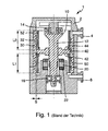
- Fig. 1 shows a longitudinal section through a belonging to the prior art vacuum pump 1.
- a suction port 4 is provided, is sucked through the gas in the vacuum pump 1. After compression, the gas is expelled from the vacuum pump 1 through an outlet 6.
- a rotor 10 which generates the pumping action together with a stator 30.
- the rotor 10 has a shaft 12, whose end facing the suction opening 4 is supported by a permanent magnet bearing 14. The opposite end is from a rolling bearing 16 supported.
- This bearing assembly has over other, also possible types of bearings, such as the flying bearing with bearings on the opposite side of the intake, the advantage that a lubricant-free bearing is used on the suction side and due to the rotor dynamic simpler storage narrow column and a shorter overall length can be achieved.
- a permanent magnet 20 is provided, which cooperates with an energized drive coil.
- the rotor 10 is set in a sufficiently fast speed. This is measured according to the pumping principle used and, with molecular principles, is generally around 10,000 revolutions per minute.
- the stator 30 has one or a plurality of helical channels 30 on its surface facing the rotor.
- a hub 40 is attached on the shaft 12. It has a first side 42 and a second side 44 opposite this first side 42. The second side 44 faces the suction opening.
- a first sleeve 50 is secured to the first side and a second sleeve 52 to the second side. Both sleeves 50, 52 cooperate with the stator 30 and its helical channel 32 to create a holweck pumping action.
- the gas flow leads through the suction opening into a gap S between the second sleeve 52 and the stator 30.
- the first sleeve 50 is arranged downstream in the gas flow of the second sleeve 52 and thus compresses toward the sleeve pressure.
- Fig. 2 the housing 2 is shown having the inlet 4.
- the rotating sleeve 52 is shown as well as the pump-active structure 32.
- FIG. 2 schematically shows how a gas molecule 60 hits the sleeve 52. Due to the probable direction of movement of the gas molecule 60, it may happen that the molecule does not enter the Holweck channels 32, but instead leaves the suction region 62 again in the direction of the recipient, that is, opposite to the direction of the arrow A. The resulting velocity is shown by the arrow 80.
- Fig. 3 shows a known from practice inlet flange 4, which is designed as an asymmetrically drilled inlet channel. This embodiment directs the gas molecules 60 in different directions of the inlet 4. The resulting velocity is shown by the arrow 80.
- Fig. 4 shows an inventive inlet geometry, which represents a further improvement over the prior art, in which the inlet 4 is formed widening in the direction of sleeve 52.
- the direction of movement of the molecules 60 is influenced so that they can no longer leave the suction flange of the pump 1 as far as possible in the direction of the recipient, ie counter to the direction of the arrow A and continue to remain in the pumping process.
- Fig. 5 shows a modified embodiment of the invention.
- the inlet 64 is according to Fig. 5 formed linear conically widening. Also according to this inlet geometry, the gas molecules, which abut the inner wall of the extension 64 of the inlet flange 4, move back in the direction of the pump chamber, so that the pumping speed of the pump also increases significantly.
- Fig. 6 1 shows a turbo-pumping stage 66 with a suction opening 62.
- the turbo-pumping stage has a rotor 68 with rotor blades 70.
- the gas molecules (not shown) enter into the vacuum pumping stage 66 in the direction of the arrow A. If the gas molecules are deflected by the rotor blades 70 in the direction of the outlet, they abut against the inner wall of the extension 64 of the suction port 62 and are in turn directed in the direction of the rotor 68.
- Fig. 7 shows a schematic representation of the pumping stage 66 with the rotor 68.
- the rotor 68 has rotor disks 72, 74 and stator disks 76, 78, wherein the rotor disks 72, 74 and the stator disks 76, 78 have opposite rotor and Statorbeschaufelept.
- a gas molecule which enters the suction opening 62 in the direction of the arrow A is deflected by the extension 64 of the suction opening 62 and "passes" through the pumping stage 66 and exits the pumping stage 66 in the direction of the arrow B.
Landscapes
- Engineering & Computer Science (AREA)
- Mechanical Engineering (AREA)
- General Engineering & Computer Science (AREA)
- Non-Positive Displacement Air Blowers (AREA)
Applications Claiming Priority (1)
| Application Number | Priority Date | Filing Date | Title |
|---|---|---|---|
| DE102013114290.7A DE102013114290A1 (de) | 2013-12-18 | 2013-12-18 | Vakuumpumpe |
Publications (3)
| Publication Number | Publication Date |
|---|---|
| EP2886870A1 true EP2886870A1 (fr) | 2015-06-24 |
| EP2886870B1 EP2886870B1 (fr) | 2017-12-20 |
| EP2886870B2 EP2886870B2 (fr) | 2020-12-23 |
Family
ID=52023216
Family Applications (1)
| Application Number | Title | Priority Date | Filing Date |
|---|---|---|---|
| EP14196002.1A Not-in-force EP2886870B2 (fr) | 2013-12-18 | 2014-12-03 | Pompe à vide avec géométrie d'admission perfectionnée |
Country Status (4)
| Country | Link |
|---|---|
| US (1) | US20150167679A1 (fr) |
| EP (1) | EP2886870B2 (fr) |
| JP (1) | JP6118784B2 (fr) |
| DE (1) | DE102013114290A1 (fr) |
Families Citing this family (2)
| Publication number | Priority date | Publication date | Assignee | Title |
|---|---|---|---|---|
| JP6578838B2 (ja) * | 2015-09-15 | 2019-09-25 | 株式会社島津製作所 | 真空ポンプおよび質量分析装置 |
| EP4293232B1 (fr) * | 2023-10-17 | 2026-05-06 | Pfeiffer Vacuum Technology AG | Pompe turbomoléculaire |
Citations (7)
| Publication number | Priority date | Publication date | Assignee | Title |
|---|---|---|---|---|
| DE19848406A1 (de) * | 1997-10-21 | 1999-05-20 | Varian Associates | Molekularpumpe mit gerippter Rotorkonstruktion |
| US6450772B1 (en) * | 1999-10-18 | 2002-09-17 | Sarcos, Lc | Compact molecular drag vacuum pump |
| EP1243796A2 (fr) * | 2001-03-24 | 2002-09-25 | Pfeiffer Vacuum GmbH | Pompe à vide |
| EP1302667A1 (fr) * | 2001-10-15 | 2003-04-16 | The BOC Group plc | Pompes à vide |
| EP2385257A2 (fr) * | 2010-05-08 | 2011-11-09 | Pfeiffer Vacuum Gmbh | Etage de pompe à vide |
| DE202010012795U1 (de) | 2010-09-21 | 2012-01-13 | Oerlikon Leybold Vacuum Gmbh | Vakuumpumpe |
| DE102011112689A1 (de) | 2011-09-05 | 2013-03-07 | Pfeiffer Vacuum Gmbh | Vakuumpumpe |
Family Cites Families (18)
| Publication number | Priority date | Publication date | Assignee | Title |
|---|---|---|---|---|
| JPS6146492A (ja) | 1984-08-11 | 1986-03-06 | Mitsuwa Seiki Co Ltd | 分子ポンプ |
| JPH0213195U (fr) * | 1988-06-30 | 1990-01-26 | ||
| FR2641582B1 (fr) * | 1989-01-09 | 1991-03-22 | Cit Alcatel | Pompe a vide du type a canal de gaede |
| JPH0475196U (fr) * | 1990-11-09 | 1992-06-30 | ||
| DE4331589C2 (de) | 1992-12-24 | 2003-06-26 | Pfeiffer Vacuum Gmbh | Vakuumpumpsystem |
| JPH0717986U (ja) * | 1993-09-08 | 1995-03-31 | 二国機械工業株式会社 | 渦流ポンプ |
| DE19508566A1 (de) | 1995-03-10 | 1996-09-12 | Balzers Pfeiffer Gmbh | Molekularvakuumpumpe mit Kühlgaseinrichtung und Verfahren zu deren Betrieb |
| DE19821634A1 (de) | 1998-05-14 | 1999-11-18 | Leybold Vakuum Gmbh | Reibungsvakuumpumpe mit Stator und Rotor |
| JP3961155B2 (ja) * | 1999-05-28 | 2007-08-22 | Bocエドワーズ株式会社 | 真空ポンプ |
| DE19930952A1 (de) * | 1999-07-05 | 2001-01-11 | Pfeiffer Vacuum Gmbh | Vakuumpumpe |
| GB9921983D0 (en) | 1999-09-16 | 1999-11-17 | Boc Group Plc | Improvements in vacuum pumps |
| GB2360066A (en) | 2000-03-06 | 2001-09-12 | Boc Group Plc | Vacuum pump |
| JP2005042709A (ja) * | 2003-07-10 | 2005-02-17 | Ebara Corp | 真空ポンプ |
| GB0414316D0 (en) | 2004-06-25 | 2004-07-28 | Boc Group Plc | Vacuum pump |
| DE202005019644U1 (de) | 2005-12-16 | 2007-04-26 | Leybold Vacuum Gmbh | Turbomolekularpumpe |
| DE102008024764A1 (de) | 2008-05-23 | 2009-11-26 | Oerlikon Leybold Vacuum Gmbh | Mehrstufige Vakuumpumpe |
| DE102009035332A1 (de) | 2009-07-30 | 2011-02-03 | Pfeiffer Vacuum Gmbh | Vakuumpumpe |
| DE102011112691A1 (de) | 2011-09-05 | 2013-03-07 | Pfeiffer Vacuum Gmbh | Vakuumpumpe |
-
2013
- 2013-12-18 DE DE102013114290.7A patent/DE102013114290A1/de not_active Withdrawn
-
2014
- 2014-12-03 EP EP14196002.1A patent/EP2886870B2/fr not_active Not-in-force
- 2014-12-05 JP JP2014246652A patent/JP6118784B2/ja not_active Expired - Fee Related
- 2014-12-16 US US14/571,355 patent/US20150167679A1/en not_active Abandoned
Patent Citations (7)
| Publication number | Priority date | Publication date | Assignee | Title |
|---|---|---|---|---|
| DE19848406A1 (de) * | 1997-10-21 | 1999-05-20 | Varian Associates | Molekularpumpe mit gerippter Rotorkonstruktion |
| US6450772B1 (en) * | 1999-10-18 | 2002-09-17 | Sarcos, Lc | Compact molecular drag vacuum pump |
| EP1243796A2 (fr) * | 2001-03-24 | 2002-09-25 | Pfeiffer Vacuum GmbH | Pompe à vide |
| EP1302667A1 (fr) * | 2001-10-15 | 2003-04-16 | The BOC Group plc | Pompes à vide |
| EP2385257A2 (fr) * | 2010-05-08 | 2011-11-09 | Pfeiffer Vacuum Gmbh | Etage de pompe à vide |
| DE202010012795U1 (de) | 2010-09-21 | 2012-01-13 | Oerlikon Leybold Vacuum Gmbh | Vakuumpumpe |
| DE102011112689A1 (de) | 2011-09-05 | 2013-03-07 | Pfeiffer Vacuum Gmbh | Vakuumpumpe |
Also Published As
| Publication number | Publication date |
|---|---|
| JP6118784B2 (ja) | 2017-04-19 |
| US20150167679A1 (en) | 2015-06-18 |
| JP2015117697A (ja) | 2015-06-25 |
| EP2886870B2 (fr) | 2020-12-23 |
| EP2886870B1 (fr) | 2017-12-20 |
| DE102013114290A1 (de) | 2015-06-18 |
Similar Documents
| Publication | Publication Date | Title |
|---|---|---|
| EP2295812B1 (fr) | Récipient repliable | |
| DE2412624C2 (de) | Molekularvakuumpumpenanordnung | |
| EP2933497B1 (fr) | Pompe à vide | |
| DE3932228A1 (de) | Turbovakuumpumpe | |
| EP0828080A2 (fr) | Pompe à effet visqueux | |
| EP1706645B1 (fr) | Pompe à vide à frottement à plusieurs étages | |
| DE102012003680A1 (de) | Vakuumpumpe | |
| EP1067290B1 (fr) | Pompe à vide | |
| DE4410656A1 (de) | Reibungspumpe | |
| WO2009141222A1 (fr) | Pompe à vide multiétagée | |
| EP2886870B1 (fr) | Pompe à vide avec géométrie d'admission perfectionnée | |
| EP2565464B1 (fr) | Pompe à vide | |
| EP3088743B1 (fr) | Étage de pompe a vide à canal latéral avec un barrage de canal qui présente une rampe du côté de l'aspiration | |
| EP3608545B1 (fr) | Pompe à vide | |
| EP2594803A1 (fr) | Pompe à vide à friction | |
| EP3032107B1 (fr) | Pompe turbomoleculaire | |
| DE102019101277A1 (de) | Axiallüfteranordnung für Fahrzeuge | |
| EP2409039A1 (fr) | Pompe à vide à entrées multiples | |
| EP4194700A1 (fr) | Pompe à vide avec étage de pompe de holweck à géométrie de holweck variable | |
| EP3045728B1 (fr) | Pompe à vide à vis | |
| DE102013112185B4 (de) | Vakuumpumpe sowie Vakuumpumpe mit wenigstens einer Turbomolekularpumpstufe | |
| EP2902637B1 (fr) | Pompe à vide | |
| EP3577346B1 (fr) | Turbocompresseur pourvu de canaux d'écoulement intégrés | |
| EP3767109B1 (fr) | Système à vide | |
| DE102013022539B3 (de) | Vakuumpumpe |
Legal Events
| Date | Code | Title | Description |
|---|---|---|---|
| PUAI | Public reference made under article 153(3) epc to a published international application that has entered the european phase |
Free format text: ORIGINAL CODE: 0009012 |
|
| 17P | Request for examination filed |
Effective date: 20141203 |
|
| AK | Designated contracting states |
Kind code of ref document: A1 Designated state(s): AL AT BE BG CH CY CZ DE DK EE ES FI FR GB GR HR HU IE IS IT LI LT LU LV MC MK MT NL NO PL PT RO RS SE SI SK SM TR |
|
| AX | Request for extension of the european patent |
Extension state: BA ME |
|
| R17P | Request for examination filed (corrected) |
Effective date: 20151126 |
|
| RBV | Designated contracting states (corrected) |
Designated state(s): AL AT BE BG CH CY CZ DE DK EE ES FI FR GB GR HR HU IE IS IT LI LT LU LV MC MK MT NL NO PL PT RO RS SE SI SK SM TR |
|
| GRAP | Despatch of communication of intention to grant a patent |
Free format text: ORIGINAL CODE: EPIDOSNIGR1 |
|
| STAA | Information on the status of an ep patent application or granted ep patent |
Free format text: STATUS: GRANT OF PATENT IS INTENDED |
|
| INTG | Intention to grant announced |
Effective date: 20170908 |
|
| GRAS | Grant fee paid |
Free format text: ORIGINAL CODE: EPIDOSNIGR3 |
|
| GRAA | (expected) grant |
Free format text: ORIGINAL CODE: 0009210 |
|
| STAA | Information on the status of an ep patent application or granted ep patent |
Free format text: STATUS: THE PATENT HAS BEEN GRANTED |
|
| AK | Designated contracting states |
Kind code of ref document: B1 Designated state(s): AL AT BE BG CH CY CZ DE DK EE ES FI FR GB GR HR HU IE IS IT LI LT LU LV MC MK MT NL NO PL PT RO RS SE SI SK SM TR |
|
| REG | Reference to a national code |
Ref country code: GB Ref legal event code: FG4D Free format text: NOT ENGLISH |
|
| REG | Reference to a national code |
Ref country code: CH Ref legal event code: EP |
|
| REG | Reference to a national code |
Ref country code: IE Ref legal event code: FG4D Free format text: LANGUAGE OF EP DOCUMENT: GERMAN |
|
| REG | Reference to a national code |
Ref country code: AT Ref legal event code: REF Ref document number: 956655 Country of ref document: AT Kind code of ref document: T Effective date: 20180115 |
|
| REG | Reference to a national code |
Ref country code: DE Ref legal event code: R096 Ref document number: 502014006638 Country of ref document: DE |
|
| REG | Reference to a national code |
Ref country code: NL Ref legal event code: MP Effective date: 20171220 |
|
| PG25 | Lapsed in a contracting state [announced via postgrant information from national office to epo] |
Ref country code: NO Free format text: LAPSE BECAUSE OF FAILURE TO SUBMIT A TRANSLATION OF THE DESCRIPTION OR TO PAY THE FEE WITHIN THE PRESCRIBED TIME-LIMIT Effective date: 20180320 Ref country code: LT Free format text: LAPSE BECAUSE OF FAILURE TO SUBMIT A TRANSLATION OF THE DESCRIPTION OR TO PAY THE FEE WITHIN THE PRESCRIBED TIME-LIMIT Effective date: 20171220 Ref country code: FI Free format text: LAPSE BECAUSE OF FAILURE TO SUBMIT A TRANSLATION OF THE DESCRIPTION OR TO PAY THE FEE WITHIN THE PRESCRIBED TIME-LIMIT Effective date: 20171220 Ref country code: SE Free format text: LAPSE BECAUSE OF FAILURE TO SUBMIT A TRANSLATION OF THE DESCRIPTION OR TO PAY THE FEE WITHIN THE PRESCRIBED TIME-LIMIT Effective date: 20171220 |
|
| REG | Reference to a national code |
Ref country code: LT Ref legal event code: MG4D |
|
| PG25 | Lapsed in a contracting state [announced via postgrant information from national office to epo] |
Ref country code: LV Free format text: LAPSE BECAUSE OF FAILURE TO SUBMIT A TRANSLATION OF THE DESCRIPTION OR TO PAY THE FEE WITHIN THE PRESCRIBED TIME-LIMIT Effective date: 20171220 Ref country code: RS Free format text: LAPSE BECAUSE OF FAILURE TO SUBMIT A TRANSLATION OF THE DESCRIPTION OR TO PAY THE FEE WITHIN THE PRESCRIBED TIME-LIMIT Effective date: 20171220 Ref country code: GR Free format text: LAPSE BECAUSE OF FAILURE TO SUBMIT A TRANSLATION OF THE DESCRIPTION OR TO PAY THE FEE WITHIN THE PRESCRIBED TIME-LIMIT Effective date: 20180321 Ref country code: BG Free format text: LAPSE BECAUSE OF FAILURE TO SUBMIT A TRANSLATION OF THE DESCRIPTION OR TO PAY THE FEE WITHIN THE PRESCRIBED TIME-LIMIT Effective date: 20180320 Ref country code: HR Free format text: LAPSE BECAUSE OF FAILURE TO SUBMIT A TRANSLATION OF THE DESCRIPTION OR TO PAY THE FEE WITHIN THE PRESCRIBED TIME-LIMIT Effective date: 20171220 |
|
| PG25 | Lapsed in a contracting state [announced via postgrant information from national office to epo] |
Ref country code: NL Free format text: LAPSE BECAUSE OF FAILURE TO SUBMIT A TRANSLATION OF THE DESCRIPTION OR TO PAY THE FEE WITHIN THE PRESCRIBED TIME-LIMIT Effective date: 20171220 |
|
| PG25 | Lapsed in a contracting state [announced via postgrant information from national office to epo] |
Ref country code: SK Free format text: LAPSE BECAUSE OF FAILURE TO SUBMIT A TRANSLATION OF THE DESCRIPTION OR TO PAY THE FEE WITHIN THE PRESCRIBED TIME-LIMIT Effective date: 20171220 Ref country code: ES Free format text: LAPSE BECAUSE OF FAILURE TO SUBMIT A TRANSLATION OF THE DESCRIPTION OR TO PAY THE FEE WITHIN THE PRESCRIBED TIME-LIMIT Effective date: 20171220 Ref country code: CY Free format text: LAPSE BECAUSE OF FAILURE TO SUBMIT A TRANSLATION OF THE DESCRIPTION OR TO PAY THE FEE WITHIN THE PRESCRIBED TIME-LIMIT Effective date: 20171220 Ref country code: EE Free format text: LAPSE BECAUSE OF FAILURE TO SUBMIT A TRANSLATION OF THE DESCRIPTION OR TO PAY THE FEE WITHIN THE PRESCRIBED TIME-LIMIT Effective date: 20171220 |
|
| PG25 | Lapsed in a contracting state [announced via postgrant information from national office to epo] |
Ref country code: IS Free format text: LAPSE BECAUSE OF FAILURE TO SUBMIT A TRANSLATION OF THE DESCRIPTION OR TO PAY THE FEE WITHIN THE PRESCRIBED TIME-LIMIT Effective date: 20180420 Ref country code: PL Free format text: LAPSE BECAUSE OF FAILURE TO SUBMIT A TRANSLATION OF THE DESCRIPTION OR TO PAY THE FEE WITHIN THE PRESCRIBED TIME-LIMIT Effective date: 20171220 Ref country code: RO Free format text: LAPSE BECAUSE OF FAILURE TO SUBMIT A TRANSLATION OF THE DESCRIPTION OR TO PAY THE FEE WITHIN THE PRESCRIBED TIME-LIMIT Effective date: 20171220 Ref country code: SM Free format text: LAPSE BECAUSE OF FAILURE TO SUBMIT A TRANSLATION OF THE DESCRIPTION OR TO PAY THE FEE WITHIN THE PRESCRIBED TIME-LIMIT Effective date: 20171220 |
|
| REG | Reference to a national code |
Ref country code: DE Ref legal event code: R026 Ref document number: 502014006638 Country of ref document: DE |
|
| PG25 | Lapsed in a contracting state [announced via postgrant information from national office to epo] |
Ref country code: MT Free format text: LAPSE BECAUSE OF FAILURE TO SUBMIT A TRANSLATION OF THE DESCRIPTION OR TO PAY THE FEE WITHIN THE PRESCRIBED TIME-LIMIT Effective date: 20171220 |
|
| PLBI | Opposition filed |
Free format text: ORIGINAL CODE: 0009260 |
|
| PLAX | Notice of opposition and request to file observation + time limit sent |
Free format text: ORIGINAL CODE: EPIDOSNOBS2 |
|
| 26 | Opposition filed |
Opponent name: LEYBOLD GMBH Effective date: 20180920 |
|
| PG25 | Lapsed in a contracting state [announced via postgrant information from national office to epo] |
Ref country code: DK Free format text: LAPSE BECAUSE OF FAILURE TO SUBMIT A TRANSLATION OF THE DESCRIPTION OR TO PAY THE FEE WITHIN THE PRESCRIBED TIME-LIMIT Effective date: 20171220 |
|
| PLBB | Reply of patent proprietor to notice(s) of opposition received |
Free format text: ORIGINAL CODE: EPIDOSNOBS3 |
|
| PG25 | Lapsed in a contracting state [announced via postgrant information from national office to epo] |
Ref country code: SI Free format text: LAPSE BECAUSE OF FAILURE TO SUBMIT A TRANSLATION OF THE DESCRIPTION OR TO PAY THE FEE WITHIN THE PRESCRIBED TIME-LIMIT Effective date: 20171220 |
|
| REG | Reference to a national code |
Ref country code: CH Ref legal event code: PL |
|
| PG25 | Lapsed in a contracting state [announced via postgrant information from national office to epo] |
Ref country code: MC Free format text: LAPSE BECAUSE OF FAILURE TO SUBMIT A TRANSLATION OF THE DESCRIPTION OR TO PAY THE FEE WITHIN THE PRESCRIBED TIME-LIMIT Effective date: 20171220 Ref country code: LU Free format text: LAPSE BECAUSE OF NON-PAYMENT OF DUE FEES Effective date: 20181203 |
|
| REG | Reference to a national code |
Ref country code: IE Ref legal event code: MM4A |
|
| REG | Reference to a national code |
Ref country code: BE Ref legal event code: MM Effective date: 20181231 |
|
| PG25 | Lapsed in a contracting state [announced via postgrant information from national office to epo] |
Ref country code: FR Free format text: LAPSE BECAUSE OF NON-PAYMENT OF DUE FEES Effective date: 20181231 Ref country code: IE Free format text: LAPSE BECAUSE OF NON-PAYMENT OF DUE FEES Effective date: 20181203 |
|
| PG25 | Lapsed in a contracting state [announced via postgrant information from national office to epo] |
Ref country code: BE Free format text: LAPSE BECAUSE OF NON-PAYMENT OF DUE FEES Effective date: 20181231 |
|
| PG25 | Lapsed in a contracting state [announced via postgrant information from national office to epo] |
Ref country code: LI Free format text: LAPSE BECAUSE OF NON-PAYMENT OF DUE FEES Effective date: 20181231 Ref country code: CH Free format text: LAPSE BECAUSE OF NON-PAYMENT OF DUE FEES Effective date: 20181231 |
|
| PG25 | Lapsed in a contracting state [announced via postgrant information from national office to epo] |
Ref country code: TR Free format text: LAPSE BECAUSE OF FAILURE TO SUBMIT A TRANSLATION OF THE DESCRIPTION OR TO PAY THE FEE WITHIN THE PRESCRIBED TIME-LIMIT Effective date: 20171220 |
|
| PG25 | Lapsed in a contracting state [announced via postgrant information from national office to epo] |
Ref country code: PT Free format text: LAPSE BECAUSE OF FAILURE TO SUBMIT A TRANSLATION OF THE DESCRIPTION OR TO PAY THE FEE WITHIN THE PRESCRIBED TIME-LIMIT Effective date: 20171220 |
|
| PG25 | Lapsed in a contracting state [announced via postgrant information from national office to epo] |
Ref country code: MK Free format text: LAPSE BECAUSE OF NON-PAYMENT OF DUE FEES Effective date: 20171220 Ref country code: HU Free format text: LAPSE BECAUSE OF FAILURE TO SUBMIT A TRANSLATION OF THE DESCRIPTION OR TO PAY THE FEE WITHIN THE PRESCRIBED TIME-LIMIT; INVALID AB INITIO Effective date: 20141203 |
|
| PG25 | Lapsed in a contracting state [announced via postgrant information from national office to epo] |
Ref country code: AL Free format text: LAPSE BECAUSE OF FAILURE TO SUBMIT A TRANSLATION OF THE DESCRIPTION OR TO PAY THE FEE WITHIN THE PRESCRIBED TIME-LIMIT Effective date: 20171220 |
|
| PUAH | Patent maintained in amended form |
Free format text: ORIGINAL CODE: 0009272 |
|
| STAA | Information on the status of an ep patent application or granted ep patent |
Free format text: STATUS: PATENT MAINTAINED AS AMENDED |
|
| 27A | Patent maintained in amended form |
Effective date: 20201223 |
|
| AK | Designated contracting states |
Kind code of ref document: B2 Designated state(s): AL AT BE BG CH CY CZ DE DK EE ES FI FR GB GR HR HU IE IS IT LI LT LU LV MC MK MT NL NO PL PT RO RS SE SI SK SM TR |
|
| REG | Reference to a national code |
Ref country code: DE Ref legal event code: R102 Ref document number: 502014006638 Country of ref document: DE |
|
| REG | Reference to a national code |
Ref country code: AT Ref legal event code: MM01 Ref document number: 956655 Country of ref document: AT Kind code of ref document: T Effective date: 20191203 |
|
| PG25 | Lapsed in a contracting state [announced via postgrant information from national office to epo] |
Ref country code: AT Free format text: LAPSE BECAUSE OF NON-PAYMENT OF DUE FEES Effective date: 20191203 |
|
| PGFP | Annual fee paid to national office [announced via postgrant information from national office to epo] |
Ref country code: GB Payment date: 20231102 Year of fee payment: 10 |
|
| PGFP | Annual fee paid to national office [announced via postgrant information from national office to epo] |
Ref country code: IT Payment date: 20231026 Year of fee payment: 10 Ref country code: DE Payment date: 20231102 Year of fee payment: 10 Ref country code: CZ Payment date: 20231030 Year of fee payment: 10 |
|
| REG | Reference to a national code |
Ref country code: DE Ref legal event code: R119 Ref document number: 502014006638 Country of ref document: DE |
|
| PG25 | Lapsed in a contracting state [announced via postgrant information from national office to epo] |
Ref country code: CZ Free format text: LAPSE BECAUSE OF NON-PAYMENT OF DUE FEES Effective date: 20241203 |
|
| GBPC | Gb: european patent ceased through non-payment of renewal fee |
Effective date: 20241203 |
|
| PG25 | Lapsed in a contracting state [announced via postgrant information from national office to epo] |
Ref country code: DE Free format text: LAPSE BECAUSE OF NON-PAYMENT OF DUE FEES Effective date: 20250701 |
|
| PG25 | Lapsed in a contracting state [announced via postgrant information from national office to epo] |
Ref country code: IT Free format text: LAPSE BECAUSE OF NON-PAYMENT OF DUE FEES Effective date: 20241203 |
|
| PG25 | Lapsed in a contracting state [announced via postgrant information from national office to epo] |
Ref country code: GB Free format text: LAPSE BECAUSE OF NON-PAYMENT OF DUE FEES Effective date: 20241203 |