EP2901820B1 - Fokussierung eines partikelstrahls unter verwendung eines magnetfeldflimmerns - Google Patents
Fokussierung eines partikelstrahls unter verwendung eines magnetfeldflimmerns Download PDFInfo
- Publication number
- EP2901820B1 EP2901820B1 EP13783421.4A EP13783421A EP2901820B1 EP 2901820 B1 EP2901820 B1 EP 2901820B1 EP 13783421 A EP13783421 A EP 13783421A EP 2901820 B1 EP2901820 B1 EP 2901820B1
- Authority
- EP
- European Patent Office
- Prior art keywords
- magnetic field
- cavity
- particle
- particle accelerator
- regenerator
- Prior art date
- Legal status (The legal status is an assumption and is not a legal conclusion. Google has not performed a legal analysis and makes no representation as to the accuracy of the status listed.)
- Active
Links
Images














Classifications
-
- H—ELECTRICITY
- H05—ELECTRIC TECHNIQUES NOT OTHERWISE PROVIDED FOR
- H05H—PLASMA TECHNIQUE; PRODUCTION OF ACCELERATED ELECTRICALLY-CHARGED PARTICLES OR OF NEUTRONS; PRODUCTION OR ACCELERATION OF NEUTRAL MOLECULAR OR ATOMIC BEAMS
- H05H7/00—Details of devices of the types covered by groups H05H9/00, H05H11/00, H05H13/00
- H05H7/10—Arrangements for ejecting particles from orbits
-
- A—HUMAN NECESSITIES
- A61—MEDICAL OR VETERINARY SCIENCE; HYGIENE
- A61N—ELECTROTHERAPY; MAGNETOTHERAPY; RADIATION THERAPY; ULTRASOUND THERAPY
- A61N5/00—Radiation therapy
- A61N5/10—X-ray therapy; Gamma-ray therapy; Particle-irradiation therapy
- A61N5/1077—Beam delivery systems
-
- H—ELECTRICITY
- H05—ELECTRIC TECHNIQUES NOT OTHERWISE PROVIDED FOR
- H05H—PLASMA TECHNIQUE; PRODUCTION OF ACCELERATED ELECTRICALLY-CHARGED PARTICLES OR OF NEUTRONS; PRODUCTION OR ACCELERATION OF NEUTRAL MOLECULAR OR ATOMIC BEAMS
- H05H13/00—Magnetic resonance accelerators; Cyclotrons
- H05H13/005—Cyclotrons
-
- H—ELECTRICITY
- H05—ELECTRIC TECHNIQUES NOT OTHERWISE PROVIDED FOR
- H05H—PLASMA TECHNIQUE; PRODUCTION OF ACCELERATED ELECTRICALLY-CHARGED PARTICLES OR OF NEUTRONS; PRODUCTION OR ACCELERATION OF NEUTRAL MOLECULAR OR ATOMIC BEAMS
- H05H13/00—Magnetic resonance accelerators; Cyclotrons
- H05H13/02—Synchrocyclotrons, i.e. frequency modulated cyclotrons
-
- H—ELECTRICITY
- H05—ELECTRIC TECHNIQUES NOT OTHERWISE PROVIDED FOR
- H05H—PLASMA TECHNIQUE; PRODUCTION OF ACCELERATED ELECTRICALLY-CHARGED PARTICLES OR OF NEUTRONS; PRODUCTION OR ACCELERATION OF NEUTRAL MOLECULAR OR ATOMIC BEAMS
- H05H7/00—Details of devices of the types covered by groups H05H9/00, H05H11/00, H05H13/00
- H05H7/04—Magnet systems, e.g. undulators, wigglers; Energisation thereof
-
- A—HUMAN NECESSITIES
- A61—MEDICAL OR VETERINARY SCIENCE; HYGIENE
- A61N—ELECTROTHERAPY; MAGNETOTHERAPY; RADIATION THERAPY; ULTRASOUND THERAPY
- A61N5/00—Radiation therapy
- A61N5/10—X-ray therapy; Gamma-ray therapy; Particle-irradiation therapy
- A61N2005/1092—Details
- A61N2005/1095—Elements inserted into the radiation path within the system, e.g. filters or wedges
-
- H—ELECTRICITY
- H05—ELECTRIC TECHNIQUES NOT OTHERWISE PROVIDED FOR
- H05H—PLASMA TECHNIQUE; PRODUCTION OF ACCELERATED ELECTRICALLY-CHARGED PARTICLES OR OF NEUTRONS; PRODUCTION OR ACCELERATION OF NEUTRAL MOLECULAR OR ATOMIC BEAMS
- H05H7/00—Details of devices of the types covered by groups H05H9/00, H05H11/00, H05H13/00
- H05H7/04—Magnet systems, e.g. undulators, wigglers; Energisation thereof
- H05H2007/046—Magnet systems, e.g. undulators, wigglers; Energisation thereof for beam deflection
Definitions
- This disclosure relates generally to focusing a particle beam in a synchrocyclotron using magnetic field flutter.
- Particle therapy systems use an accelerator to generate a particle beam for treating afflictions, such as tumors.
- particles are accelerated in orbits inside a cavity in the presence of a magnetic field, and removed from the cavity through an extraction channel.
- An example of an accelerator that may be used in a particle therapy system is a synchrocyclotron.
- a plasma column is produced using ionized gas (e.g., hydrogen).
- ionized gas e.g., hydrogen
- An RF voltage is applied to extract particles from the plasma column, and a magnetic field is applied to maintain those particles in spiral orbits as they increase in energy and radius until they reach an extraction region.
- the RF voltage is swept across a range of frequencies to account for relativistic effects on the particles (e.g., increasing particle mass) when accelerating particles from the plasma column.
- US 3,024,379 describes an arrangement for accelerating particles that, as viewed in the direction of circulation of the accelerated particles, within an azimuthal angle of about 60° after the regenerator, there are provided means of ferromagnetic material for restricting the paths in an axial direction, these restricting means causing the decrease of the magnetic field upon increasing radius to be intensified through a small azimuthal angle in the region of the last path of the particles.
- US 2,812,463 describes a magnetic regenerative deflector for cyclotrons that includes a peeler which reduces the normal orbit-controlling magnetic field to a constant weakened condition in a narrow azimuthal sector located adjacent the outer periphery of the spiral path and azimuthally beyond the channel mouth.
- the particle orbit is thereby caused to oscillate radially, and the amplitude of oscillation grows exponentially with successive revolutions of the particle so that after several such revolutions the particle enters the mouth of the channel and is conducted thereby out of the magnetic field and toward the target.
- US 4,641, 057 describes a synchrocyclotron with superconducting coils.
- the coils are provided in a vessel which is supported by low heat leak members in a cryostat.
- a liquified gas (helium) is provided in the vessel to cool the coils so as to render them superconducting.
- GB1485329 describes an isochronous cyclotron having flutter poles, trimming of the magnetic field, e.g. to permit operation at different output energies, is effected by rods of magnetic metal movable in bores passing through the polepieces. An identical array of rods in each polepiece is employed, the rods being graded in size in the radial direction.
- the cyclotron may have a magnetic yoke which acts as a shield and includes cryostats containing superconductive main coils.
- GB 1360085 describes a magnetic focusing device for particle accelerators of the isochronous cyclotron type, capable of exciting within a main air gap a controlled magnetic field. the particles (e.g., increasing particle mass) when accelerating particles from the plasma column.
- An example particle accelerator may include the following: a voltage source to sweep a radio frequency (RF) voltage in a cavity to accelerate particles from a plasma column, where the cavity has a magnetic field causing particles accelerated from the plasma column to move orbitally within the cavity, and where the magnetic field has flux that bows at edges of the cavity; a regenerator to provide a magnetic field bump within the cavity to thereby change successive orbits of the particles accelerated from the plasma column so that, eventually, particles output to an extraction point, where the regenerator is located at a radius in the cavity relative to the plasma column; and ferromagnetic arrangements located in the cavity proximate to the radius, where each ferromagnetic arrangement provides a magnetic field bump, and where ferromagnetic arrangements adjacent to the regenerator are separated from the regenerator by a space.
- This example particle accelerator may include one or more of the following features, either alone or in combination.
- a combination of the space, the regenerator and the ferromagnetic arrangements produce magnetic field fluctuations having a component at an angle to a particle orbit to counteract at least part of a reduction in vertical focusing caused by the magnetic field bump.
- the magnetic field may be at least 4 Tesla and the magnetic field bump produced by the regenerator may be at most 2 Tesla.
- the particle accelerator may be a synchrocyclotron.
- the ferromagnetic arrangements produce magnetic field flutter, which comprises an azimuthally averaged fractional normalized magnetic field variance that is between 0.25% and 20%.
- An example proton therapy system may include the foregoing particle accelerator; and a gantry on which the particle accelerator is mounted.
- the gantry is rotatable relative to a patient position.
- Protons are output essentially directly from the synchrocyclotron to the patient position.
- the particle accelerator may be a synchrocyclotron.
- An example particle accelerator includes the following: a voltage source to sweep a radio frequency (RF) voltage in a cavity to accelerate particles from a plasma column, where the cavity has a magnetic field causing particles accelerated from the plasma column to move orbitally within the cavity, and where the magnetic field has flux that is substantially straight throughout the cavity.
- the cavity includes alternating regions of first magnetic field and second magnetic field, where the first magnetic field is different from the second magnetic field to produce magnetic fluctuations having a component at an angle that is substantially perpendicular to particle orbits within the cavity.
- This example particle accelerator may include one or more of the following features, either alone or in combination.
- the alternating regions may have different levels of ferromagnetic material.
- the alternating regions may include regions of ferromagnetic material and regions absent ferromagnetic material.
- the alternating regions may be pie-shaped, each with a point at the plasma column and an edge at an edge of the cavity.
- the alternating regions may have pinwheel shapes, each with a point at the plasma column and an edge at an edge of the cavity.
- the cavity may be defined by magnetic structures.
- the alternating regions may include vertically aligned alternating regions, one which is connected to a first magnetic structure and another of which is connected to a second magnetic structure.
- the magnetic fluctuations may vertically focus particles in orbits in the cavity.
- the particle accelerator may be a synchrocyclotron.
- first magnetic field and second magnetic field comprise magnetic field flutter, which comprises an azimuthally averaged fractional normalized magnetic field variance that is between 0.25% and 20%.
- Each example particle accelerator may include magnetic structures defining the cavity in which particles are accelerated, where the particles are for output as a particle beam that has a selected energy from among a range of energies.
- An example proton therapy system includes the foregoing particle accelerator; and a gantry on which the particle accelerator mounted.
- the gantry is rotatable relative to a patient position.
- Protons are output essentially directly from the particle accelerator the patient position.
- the particle accelerator may be a synchrocyclotron.
- Control of the various systems described herein, or portions thereof, may be implemented via a computer program product that includes instructions that are stored on one or more non-transitory machine-readable storage media, and that are executable on one or more processing devices.
- the systems described herein, or portions thereof, may be implemented as an apparatus, method, or electronic system that may include one or more processing devices and memory to store executable instructions to implement control of the stated functions.
- a particle accelerator for use in an example system, such as a proton or ion therapy system.
- the system includes a particle accelerator - in this example, a synchrocyclotron - mounted on a gantry.
- the gantry enables the accelerator to be rotated around a patient position, as explained in more detail below.
- the gantry is steel and has two legs mounted for rotation on two respective bearings that lie on opposite sides of a patient.
- the particle accelerator is supported by a steel truss that is long enough to span a treatment area in which the patient lies and that is attached stably at both ends to the rotating legs of the gantry. As a result of rotation of the gantry around the patient, the particle accelerator also rotates.
- the particle accelerator (e.g., the synchrocyclotron) includes a cryostat that holds a superconducting coil for conducting a current that generates a magnetic field (B).
- the cryostat uses liquid helium (He) to maintain the coil at superconducting temperatures, e.g., 4° Kelvin (K).
- He liquid helium
- K 4° Kelvin
- Magnetic yokes are adjacent (e.g., around) the cryostat, and define a cavity in which particles are accelerated.
- the magnetic field in the cavity (referred to as the "background magnetic field") is at least 4Tesla, 5 Tesla, or 6 Tesla, and may be more (e.g., 8 Tesla, 8.5 Tesla, 9 Tesla, 9.5 Tesla, 10 Tesla, 10.5 Tesla, or more).
- the cryostat is attached to the magnetic yokes through straps or the like.
- the particle accelerator includes a particle source (e.g., a Penning Ion Gauge - PIG source) to provide a plasma column to the cavity. Hydrogen gas is ionized to produce the plasma column.
- a voltage source provides a radio frequency (RF) voltage to the cavity to accelerate particles from the plasma column.
- the particle accelerator is a synchrocyclotron. Accordingly, the RF voltage is swept across a range of frequencies to account for relativistic effects on the particles (e.g., increasing particle mass) when extracting particles from the column.
- the magnetic field produced by the coil causes particles accelerated from the plasma column to accelerate orbitally within the cavity.
- a magnetic field regenerator (“regenerator”) is positioned near the edge of the cavity to adjust the existing magnetic field at this location to thereby change locations (e.g., the pitch and angle) of successive orbits of the particles accelerated from the plasma column so that, eventually, the particles output to an extraction channel that passes through the yokes.
- the regenerator may increase the magnetic field at a point in the cavity (e.g., it may produce a magnetic field "bump" at an area of the cavity), thereby causing each successive orbit of particles at that point to precess outward toward the entry point of the extraction channel until it reaches the extraction channel.
- the magnetic field bump is between 0.5 Tesla and 2 Tesla; however, the magnetic field bump may be more or less than these values in different systems.
- the extraction channel receives particles accelerated from the plasma column and outputs the received particles from the cavity.
- the regenerator is a single ferromagnetic arrangement that is configured to generate a magnetic field bump having a specific size and shape.
- a single ferromagnetic arrangement may be a single contiguous or physically connected structure or it may be two vertically-aligned, but physically unconnected ferromagnetic structures (e.g., one on each yoke) separated by empty space through which magnetic flux passes.
- Vertical alignment may include alignment between yokes and includes any appropriately aligned whole or part of the unconnected ferromagnetic structures.
- the magnetic field in the cavity is high (e.g., at least 4 Tesla), there can be a relatively high magnetic field gradient produced as the field passes over the coil.
- the magnetic field decreases from about 9 Tesla at the center of the cavity (at about the location of the plasma column) to about zero as it passes over the superconducting coil to about -2 Tesla on the other side of the superconducting coil.
- the magnetic field lines bow outwardly at edges of the cavity. The amount of bowing increases from the center of the cavity (at about the location of the particle source), where the bowing is about zero (i.e., the magnetic field lines are essentially straight).
- the bowed magnetic fields at edges of the cavity effect vertical focusing (also known as "weak focusing") on a particle beam, particularly at the cavity edges where bowing is most pronounced.
- Vertical focusing occurs as particles attempt to escape their orbits by moving upward or downward along the bowed magnetic field lines.
- a particle attempting to travel upward or downward is faced with a magnetic force that is opposite to its attempted direction of travel.
- the magnetic field bump produced by the regenerator can disrupt the vertical focusing produced in the manner described above.
- the magnetic field bump can counteract or move the bowing of the magnetic field lines, at least in the position where it is located, thereby disrupting vertical focusing.
- "flutter bricks" are added on each side of the regenerator at about the same (although not necessarily exactly the same) radial location of the regenerator (where radial location is a distance measured relative to the plasma column at the center of the cavity). A space (or void) is between each flutter brick and the regenerator.
- the flutter bricks are ferromagnetic arrangements that introduce magnetic field fluctuations (referred to as “magnetic flutter” or simply “flutter”) into the magnetic field at about the radial location of the flutter bricks and the regenerator.
- Flutter results from azimuthal changes in adjacent magnetic fields produced by magnetic "hills” and “valleys", which are, respectively, regions of higher and lower magnetic field.
- the flutter bricks and the regenerator constitute the hills, whereas the empty space between each flutter brick and the regenerator constitutes a valley.
- the differences in magnetic field between the hills and valleys produces sufficient perturbation of magnetic field lines in appropriate radial regions such that the resulting magnetic field lines have enough of a radial component at an angle to the particle beam to cause vertical focusing.
- each flutter brick is a single ferromagnetic arrangement that is configured to generate a magnetic field bump having a specific size and shape.
- a single ferromagnetic arrangement may be a single contiguous or physically connected structure or it may be two vertically-aligned, but physically unconnected ferromagnetic structures (e.g., one on each yoke) separated by empty space through which magnetic flux passes.
- vertical alignment includes alignment between yokes and includes any. appropriately aligned whole or part of the ferromagnetic structures.
- the magnetic field in the cavity may be controlled so as to reduce bowing within the cavity. This may be done, e.g., by varying the cross-sectional shape of the magnetic yokes that define the cavity. As such, there may be little or no vertical focusing produced inherently by the background magnetic field, as described above.
- magnetic flutter may be used to effect vertical focusing of the particle beam.
- flutter bricks of the type described above may be arranged at various radial locations in the cavity.
- a magnetic hill/valley arrangement may be implemented in the cavity.
- each part (hill or valley) of the arrangement may be pie shaped, in which each part has a point at the plasma column and an edge at an edge of the cavity.
- each part (hill or valley) of the arrangement may be pinwheel shaped, in which each part has a point at the plasma column and an edge at an edge of the cavity. Shapes other than these may also be used. Likewise, variations on the shapes may also be used.
- the RF voltage has to sweep to compensate for a decreasing magnetic field caused by vertical focusing.
- less of an RF sweep may be needed in terms of range and/or magnitude since the RF sweep may only track particle mass increase.
- the features described herein may be used in a single particle accelerator, and any two or more of the features may be combined in a single particle accelerator.
- the particle accelerator may be used in any type of medical or non-medical application.
- An example of a particle therapy system in which the foregoing features may be used is provided below.
- a charged particle radiation therapy system 500 includes a beam-producing particle accelerator 502 having a weight and size small enough to permit it to be mounted on a rotating gantry 504 with its output directed straight (that is, essentially directly) from the accelerator housing toward a patient 506.
- the steel gantry has two legs 508, 510 mounted for rotation on two respective bearings 512, 514 that lie on opposite sides of the patient.
- the accelerator is supported by a steel truss 516 that is long enough to span a treatment area 518 in which the patient lies (e.g., twice as long as a tall person, to permit the person to be rotated fully within the space with any desired target area of the patient remaining in the line of the beam) and is attached stably at both ends to the rotating legs of the gantry.
- the rotation of the gantry is limited to a range 520 of less than 360 degrees, e.g., about 180 degrees, to permit a floor 522 to extend from a wall of the vault 524 that houses the therapy system into the patient treatment area.
- the limited rotation range of the gantry also reduces the required thickness of some of the walls, which provide radiation shielding of people outside the treatment area.
- a range of 180 degrees of gantry rotation is enough to cover all treatment approach angles, but providing a larger range of travel can be useful.
- the range of rotation may be between 180 and 330 degrees and still provide clearance for the therapy floor space.
- the horizontal rotational axis 532 of the gantry is located nominally one meter above the floor where the patient and therapist interact with the therapy system. This floor is positioned about 3 meters above the bottom floor of the therapy system shielded vault.
- the accelerator can swing under the raised floor for delivery of treatment beams from below the rotational axis.
- the patient couch moves and rotates in a substantially horizontal plane parallel to the rotational axis of the gantry.
- the couch can rotate through a range 534 of about 270 degrees in the horizontal plane with this configuration. This combination of gantry and patient rotational ranges and degrees of freedom allow the therapist to select virtually any approach angle for the beam. If needed, the patient can be placed on the couch in the opposite orientation and then all possible angles can be used.
- the accelerator uses a synchrocyclotron configuration having a very high magnetic field superconducting electromagnetic structure. Because the bend radius of a charged particle of a given kinetic energy is reduced in direct proportion to an increase in the magnetic field applied to it, the very high magnetic field superconducting magnetic structure permits the accelerator to be made smaller and lighter.
- the synchrocyclotron uses a magnetic field that is uniform in rotation angle and falls off in strength with increasing radius. Such a field shape can be achieved regardless of the magnitude of the magnetic field, so in theory there is no upper limit to the magnetic field strength (and therefore the resulting particle energy at a fixed radius) that can be used in a synchrocyclotron.
- Superconducting materials lose their superconducting properties in the presence of very high magnetic fields.
- High performance superconducting wire windings are used to allow very high magnetic fields to be achieved.
- cryo-coolers are used to bring the superconducting coil windings to temperatures near absolute zero. Using cryo-coolers can reduce complexity and cost.
- the synchrocyclotron is supported on the gantry so that the beam is generated directly in line with the patient.
- the gantry permits rotation of the cyclotron about a horizontal rotational axis that contains a point (isocenter 540) within, or near, the patient.
- the split truss that is parallel to the rotational axis, supports the cyclotron on both sides.
- a patient support area can be accommodated in a wide area around the isocenter.
- a patient support table can be positioned to move relative to and to rotate about a vertical axis 542 through the isocenter so that, by a combination of gantry rotation and table motion and rotation, any angle of beam direction into any part of the patient can be achieved.
- the two gantry arms are separated by more than twice the height of a tall patient, allowing the couch with patient to rotate and translate in a horizontal plane above the raised floor.
- Limiting the gantry rotation angle allows for a reduction in the thickness of at least one of the walls surrounding the treatment room. Thick walls, typically constructed of concrete, provide radiation protection to individuals outside the treatment room. A wall downstream of a stopping proton beam may be about twice as thick as a wall at the opposite end of the room to provide an equivalent level of protection. Limiting the range of gantry rotation enables the treatment room to be sited below earth grade on three sides, while allowing an occupied area adjacent to the thinnest wall reducing the cost of constructing the treatment room.
- the superconducting synchrocyclotron 502 operates with a peak magnetic field in a pole gap of the synchrocyclotron of 8.8 Tesla.
- the synchrocyclotron produces a beam of protons having an energy of 250 MeV.
- the field strength could be in the range of 4 to 20 or 6 to 20 Tesla and the proton energy could be in the range of 150 to 300 MeV
- the radiation therapy system described in this example is used for proton radiation therapy, but the same principles and details can be applied in analogous systems for use in heavy ion (ion) treatment systems.
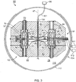
- an example synchrocyclotron 10 (e.g., 502 in Fig. 1 ) includes a magnet system 12 that contains an particle source 90, a radiofrequency drive system 91, and a beam extraction system 38.
- the magnetic field established by the magnet system has a shape appropriate to maintain focus of a contained proton beam using a combination of a split pair of annular superconducting coils 40, 42 and a pair of shaped ferromagnetic (e.g., low carbon steel) pole faces 44, 46.
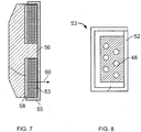
- the two superconducting magnet coils are centered on a common axis 47 and are spaced apart along the axis. As shown in Figs. 7 and 8 , the coils are formed by of Nb 3 Sn-based superconducting 0.8 mm diameter strands 48 (that initially comprise a niobium-tin core surrounded by a copper sheath) deployed in a twisted cable-in-channel conductor geometry. After seven individual strands are cabled together, they are heated to cause a reaction that forms the final (brittle) superconducting material of the wire.
- the wires are soldered into the copper channel (outer dimensions 3.18 x 2.54 mm and inner dimensions 2.08 x 2.08 mm) and covered with insulation 52 (in this example, a woven fiberglass material).
- the copper channel containing the wires 53 is then wound in a coil having a rectangular cross-section of 8.55 cm x 19.02 cm, having 26 layers and 49 turns per layer.
- the wound coil is then vacuum impregnated with an epoxy compound.
- the finished coils are mounted on an annular stainless steel reverse bobbin 56. Heater blankets 55 are placed at intervals in the layers of the windings to protect the assembly in the event of a magnet quench.
- the entire coil can then be covered with copper sheets to provide thermal conductivity and mechanical stability and then contained in an additional layer of epoxy.
- the precompression of the coil can be provided by heating the stainless steel reverse bobbin and fitting the coils within the reverse bobbin.
- the reverse bobbin inner diameter is chosen so that when the entire mass is cooled to 4 K, the reverse bobbin stays in contact with the coil and provides some compression. Heating the stainless steel reverse bobbin to approximately 50 degrees C and fitting coils at a temperature of 100 degrees Kelvin can achieve this.
- the geometry of the coil is maintained by mounting the coils in a reverse rectangular bobbin 56 to exert a restorative force 60 that works against the distorting force produced when the coils are energized.
- the coil position is maintained relative to the magnet yoke and cryostat using a set of warm-to-cold support straps 402, 404, 406. Supporting the cold mass with thin straps reduces the heat leakage imparted to the cold mass by the rigid support system.
- the straps are arranged to withstand the varying gravitational force on the coil as the magnet rotates on board the gantry.
- Each warm-to-cold support includes one S2 fiberglass link and one carbon fiber link.
- the carbon fiber link is supported across pins between the warm yoke and an intermediate temperature (50 - 70 K), and the S2 fiberglass link 408 is supported across the intermediate temperature pin and a pin attached to the cold mass.
- Each link is 5 cm long (pin center to pin center) and is 17 mm wide. The link thickness is 9 mm.
- Each pin is made of high strength stainless steel and is 40 mm in diameter.
- the field strength profile as a function of radius is determined largely by choice of coil geometry and pole face shape; the pole faces 44, 46 of the permeable yoke material can be contoured to fine tune the shape of the magnetic field to ensure that the particle beam remains focused during acceleration.
- the superconducting coils are maintained at temperatures near absolute zero (e.g., about 4 degrees Kelvin) by enclosing the coil assembly (the coils and the bobbin) inside an evacuated annular aluminum or stainless steel cryostatic chamber 70 that provides a free space around the coil structure, except at a limited set of support points 71, 73.
- the outer wall of the cryostat may be made of low carbon steel to provide an additional return flux path for the magnetic field.
- the temperature near absolute zero is achieved and maintained using one single-stage Gifford-McMahon cryo-cooler and three two-stage Gifford McMahon cryo-coolers.
- Each two stage cryo-cooler has a second stage cold end attached to a condenser that recondenses Helium vapor into liquid Helium.
- the cryo-cooler heads are supplied with compressed Helium from a compressor.
- the single-stage Gifford-McMahon cryo-cooler is arranged to cool high temperature (e.g., 50 - 70 degrees Kelvin) leads that supply current to the superconducting windings.
- the temperature near absolute zero is achieved and maintained using two Gifford-McMahon cryo-coolers 72, 74 that are arranged at different positions on the coil assembly.
- Each cryo-cooler has a cold end 76 in contact with the coil assembly.
- the cryo-cooler heads 78 are supplied with compressed Helium from a compressor 80.
- Two other Gifford-McMahon cryo-coolers 77, 79 are arranged to cool high temperature (e.g., 60 - 80 degrees Kelvin) leads that supply current to the superconducting windings.
- the coil assembly and cryostatic chambers are mounted within and fully enclosed by two halves 81, 83 of a pillbox-shaped magnet yoke 82.
- the inner diameter of the coil assembly is about 74.6 cm.
- the iron yoke 82 provides a path for the return magnetic field flux 84 and magnetically shields the volume 86 between the pole faces 44, 46 to prevent external magnetic influences from perturbing the shape of the magnetic field within that volume.
- the yoke also serves to decrease the stray magnetic field in the vicinity of the accelerator.
- the synchrocyclotron may have an active return system to reduce stray magnetic fields. An example of an active return system is described in U.S. Patent Application No.
- the synchrocyclotron includes a particle source 90 of a Penning ion gauge geometry located near the geometric center 92 of the magnet structure 82.
- the particle source may be as described below, or the particle source may be of the type described in U.S. Patent Application No. 11/948,662 .
- Particle source 90 is fed from a supply 99 of hydrogen through a gas line 101 and tube 194 that delivers gaseous hydrogen.
- Electric cables 94 carry an electric current from a current source 95 to stimulate electron discharge from cathodes 192, 190 that are aligned with the magnetic field, 200.
- the gas in gas tube 101 may include a mixture of hydrogen and one or more other gases.
- the mixture may contain hydrogen and one or more of the noble gases, e.g., helium, neon, argon, krypton, xenon and/or radon (although the mixture is not limited to use with the noble gases).
- the mixture may be a mixture of hydrogen and helium.
- the mixture may contain about 75% or more of hydrogen and about 25% or less of helium (with possible trace gases included).
- the mixture may contain about 90% or more of hydrogen and about 10% or less of helium (with possible trace gases included).
- the hydrogen/helium mixture may be any of the following: >95%/ ⁇ 5%, >90%/ ⁇ 10%, >85%/ ⁇ 15%, >80%/ ⁇ 20%, >75%/ ⁇ 20%, and so forth.
- Possible advantages of using a noble (or other) gas in combination with hydrogen in the particle source may include: increased beam intensity, increased cathode longevity, and increased consistency of beam output.
- the discharged electrons ionize the gas exiting through a small hole from tube 194 to create a supply of positive ions (protons) for acceleration by one semicircular (dee-shaped) radio-frequency plate 100 that spans half of the space enclosed by the magnet structure and one dummy dee plate 102.
- one semicircular (dee-shaped) radio-frequency plate 100 that spans half of the space enclosed by the magnet structure and one dummy dee plate 102.
- all (or a substantial part) of the tube containing plasma is removed at the acceleration region, thereby allowing ions to be more rapidly accelerated in a relatively high magnetic field.
- the dee plate 100 is a hollow metal structure that has two semicircular surfaces 103, 105 that enclose a space 107 in which the protons are accelerated during half of their rotation around the space enclosed by the magnet structure.
- a duct 109 opening into the space 107 extends through the yoke to an external location from which a vacuum pump 111 can be attached to evacuate the space 107 and the rest of the space within a vacuum chamber 119 in which the acceleration takes place.
- the dummy dee 102 comprises a rectangular metal ring that is spaced near to the exposed rim of the dee plate. The dummy dee is grounded to the vacuum chamber and magnet yoke.
- the dee plate 100 is driven by a radio-frequency signal that is applied at the end of a radio-frequency transmission line to impart an electric field in the space 107.
- the radio frequency electric field is made to vary in time as the accelerated particle beam increases in distance from the geometric center.
- the radio frequency electric field may be controlled in the manner described in U.S. Patent Application No. 11/948,359 , entitled "Matching A Resonant Frequency Of A Resonant Cavity To A Frequency Of An Input Voltage".
- the magnet structure is arranged to reduce the capacitance between the radio frequency plates and ground. This is done by forming holes with sufficient clearance from the radio frequency structures through the outer yoke and the cryostat housing and making sufficient space between the magnet pole faces.
- the high voltage alternating potential that drives the dee plate has a frequency that is swept downward during the accelerating cycle to account for the increasing relativistic mass of the protons and the decreasing magnetic field.
- the dummy dee does not require a hollow semi-cylindrical structure as it is at ground potential along with the vacuum chamber walls.
- Other plate arrangements could be used such as more than one pair of accelerating electrodes driven with different electrical phases or multiples of the fundamental frequency.
- the RF structure can be tuned to keep the Q high during the required frequency sweep by using, for example, a rotating capacitor having intermeshing rotating and stationary blades. During each meshing of the blades, the capacitance increases, thus lowering the resonant frequency of the RF structure.
- the blades can be shaped to create a precise frequency sweep required.
- a drive motor for the rotating condenser can be phase locked to the RF generator for precise control. One bunch of particles is accelerated during each meshing of the blades of the rotating condenser.
- the vacuum chamber 119 in which the acceleration occurs is a generally cylindrical container that is thinner in the center and thicker at the rim.
- the vacuum chamber encloses the RF plates and the particle source and is evacuated by the vacuum pump 111. Maintaining a high vacuum insures that accelerating ions are not lost to collisions with gas molecules and enables the RF voltage to be kept at a higher level without arcing to ground.
- Protons traverse a generally spiral orbital path beginning at the particle source. In half of each loop of the spiral path, the protons gain energy as they pass through the RF electric field in space 107. As the ions gain energy, the radius of the central orbit of each successive loop of their spiral path is larger than the prior loop until the loop radius reaches the maximum radius of the pole face. At that location a magnetic and electric field perturbation directs ions into an area where the magnetic field rapidly decreases, and the ions depart the area of the high magnetic field and are directed through an evacuated tube 38, referred to herein as the extraction channel, to exit the yoke of the cyclotron.
- a magnetic regenerator may be used to change the magnetic field perturbation to direct the ions.
- the ions exiting the cyclotron will tend to disperse as they enter the area of markedly decreased magnetic field that exists in the room around the cyclotron.
- Beam shaping elements 107, 109 in the extraction channel 38 redirect the ions so that they stay in a straight beam of limited spatial extent.
- the magnetic field within the pole gap needs to have certain properties to maintain the beam within the evacuated chamber as it accelerates.
- r the radius of the beam and B is the magnetic field.
- the ferromagnetic pole face is designed to shape the magnetic field generated by the coils so that the field index n is maintained positive and less than 0.2 in the smallest diameter consistent with a 250 MeV beam in the given magnetic field.
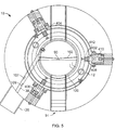
- Beam formation system 125 As the beam exits the extraction channel it is passed through a beam formation system 125 ( Fig. 5 ) that can be programmably controlled to create a desired combination of scattering angle and range modulation for the beam. Beam formation system 125 may be used in conjunction with an inner gantry 601 ( Fig. 14 ) to direct a beam to the patient.
- the plates absorb energy from the applied radio frequency field as a result of conductive resistance along the surfaces of the plates. This energy appears as heat and is removed from the plates using water cooling lines 108 that release the heat in a heat exchanger 113 ( Fig. 3 ).
- the separate magnetic shield includes of a layer 117 of ferromagnetic material (e.g., steel or iron) that encloses the pillbox yoke, separated by a space 116.
- This configuration that includes a sandwich of a yoke, a space, and a shield achieves adequate shielding for a given leakage magnetic field at lower weight.
- the gantry allows the synchrocyclotron to be rotated about the horizontal rotational axis 532.
- the truss structure 516 has two generally parallel spans 580, 582.
- the synchrocyclotron is cradled between the spans about midway between the legs.
- the gantry is balanced for rotation about the bearings using counterweights 122, 124 mounted on ends of the legs opposite the truss.
- the gantry is driven to rotate by an electric motor mounted to one or both of the gantry legs and connected to the bearing housings by drive gears .
- the rotational position of the gantry is derived from signals provided by shaft angle encoders incorporated into the gantry drive motors and the drive gears.
- the beam formation system 125 acts on the ion beam to give it properties suitable for patient treatment.
- the beam may be spread and its depth of penetration varied to provide uniform radiation across a given target volume.
- the beam formation system can include passive scattering elements as well as active scanning elements.
- synchrocyclotron control electronics may include, e.g., one or more computers programmed with appropriate programs to effect control.
- the control of the gantry, the patient support, the active beam shaping elements, and the synchrocyclotron to perform a therapy session is achieved by appropriate therapy control electronics (not shown).
- the gantry bearings are supported by the walls of a cyclotron vault 524.
- the gantry enables the cyclotron to be swung through a range 520 of 180 degrees (or more) including positions above, to the side of, and below the patient.
- the vault is tall enough to clear the gantry at the top and bottom extremes of its motion.
- a maze 146 sided by walls 148, 150 provides an entry and exit route for therapists and patients. Because at least one wall 152 is not in line with the proton beam directly from the cyclotron, it can be made relatively thin and still perform its shielding function.
- the other three side walls 154, 156, 150/148 of the room which may need to be more heavily shielded, can be buried within an earthen hill (not shown).
- the required thickness of walls 154, 156, and 158 can be reduced, because the earth can itself provide some of the needed shielding.
- a therapy room 160 may be constructed within the vault.
- the therapy room is cantilevered from walls 154, 156, 150 and the base 162 of the containing room into the space between the gantry legs in a manner that clears the swinging gantry and also maximizes the extent of the floor space 164 of the therapy room.
- Periodic servicing of the accelerator can be accomplished in the space below the raised floor.
- the accelerator is rotated to the down position on the gantry, full access to the accelerator is possible in a space separate from the treatment area. Power supplies, cooling equipment, vacuum pumps and other support equipment can be located under the raised floor in this separate space.
- the patient support 170 can be mounted in a variety of ways that permit the support to be raised and lowered and the patient to be rotated and moved to a variety of positions and orientations.
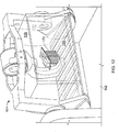
- a beam-producing particle accelerator of the type described herein in this case synchrocyclotron 604, is mounted on rotating gantry 605.
- Rotating gantry 605 is of the type described herein, and can angularly rotate around patient support 606. This feature enables synchrocyclotron 604 to provide a particle beam directly to the patient from various angles. For example, as in Fig. 14 , if synchrocyclotron 604 is above patient support 606, the particle beam may be directed downwards toward the patient. Alternatively, if synchrocyclotron 604 is below patient support 606, the particle beam may be directed upwards toward the patient. The particle beam is applied directly to the patient in the sense that an intermediary beam routing mechanism is not required.
- a routing mechanism in this context, is different from a shaping or sizing mechanism in that a shaping or sizing mechanism does not re-route the beam, but rather sizes and/or shapes the beam while maintaining the same general trajectory of the beam.
- the synchrocyclotron may be a variable-energy device, such as that described below and in U.S. Patent Application No. 13/916,401, filed on June 12, 2013 .
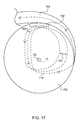
- Fig. 15 shows a top view of a portion of a cavity 700 in which particles are accelerated orbitally (e.g., in outward spiral orbits).
- a particle source 701 examples of which are described above, is disposed at about the center of the cavity.
- Charged particles e.g., protons or ions
- the charged particles accelerate outwardly in orbits toward, and eventually reaching, magnetic field regenerator 702.
- regenerator 702 is a single ferromagnetic arrangement made, e.g., of steel, iron, or any other type of ferromagnetic material.
- Regenerator 702 may include portions thereof connected to respective halves of each magnetic yoke.
- Regenerator 702 alters the background magnetic field that causes the outward orbital acceleration.
- regenerator 702 augments that magnetic field, e.g., it provides a bump in the field by enhancing the magnetic field at its location.
- the bump in the background magnetic field affects the particle orbits in a way that causes the orbits to move outwardly towards extraction channel 703. Eventually, the orbits enter extraction channel 703, from which they exit.
- a particle beam orbit approaches and interacts with regenerator 702.
- the particle beam turns a bit more there and, instead of being circular, it precesses to the extraction channel.
- Fig. 16 shows the magnetic field (B) plotted against the radius (r) relative to the particle source (701).
- B varies from about 9 Tesla (T) to about -2T.
- the magnetic field may vary from about 4T, 5T, 6T, 7T, 8T, 8.5T, 9.5T, 10T, 105T, and so forth to -2T or other values.
- the 9T occurs at about the center of cavity 700.
- the polarity of the magnetic field changes after the magnetic field crosses the superconducting coil, resulting in about -2T on the exterior of the coil, eventually fading to about zero.
- the magnetic field bump 705 occurs at the point of the regenerator.
- Fig. 16 also shows the magnetic field plot relative to a cross-section 706 of a bobbin 706 having extraction channel 703 between two superconducting coils 709, 710.
- Fig. 18 shows magnetic effects of the regenerator. More specifically, as shown in Fig. 18 , regenerator 702 produces a magnetic field depicted by magnetic field lines 750. Magnetic field lines 750 create a magnetic localized deficiency 753 in the background magnetic field. This localized deficiency is also depicted in Fig. 16 . More specifically, as noted above, Fig. 16 shows magnetic field bump 705 (e.g., 0.5T to 2T) produced by regenerator 702, along with the corresponding localized deficiency 753 in the background magnetic field. As shown, the localized deficiency 753 is relatively small in comparison to the background magnetic field. As such, its effect on precession of the orbits is relatively small. As a result, a single regenerator can be used having characteristics similar to those described herein.
- magnetic field lines 750 create a magnetic localized deficiency 753 in the background magnetic field. This localized deficiency is also depicted in Fig. 16 . More specifically, as noted above, Fig
- regenerator 702 causes changes in the angle 780 and pitch 781 of orbits 710 so that they move toward extraction channel 703.
- the magnetic field strength is sufficiently low to enable the particle beam to enter the extraction channel and to proceed therethrough.
- extraction channel 703 contains various magnetic structures 711 for adding and/or subtracting dipole fields to direct the entering particle beam through extraction channel 703, to beam shaping elements.
- Fig. 19 shows a cross-section of cavity 700 and the magnetic field lines 800 between the yokes.
- magnetic field lines 800 increasingly bow towards the edges of the cavity, with the most pronounced bowing appearing at the edges.
- this bowing causes vertical focusing; however, that vertical focusing is disrupted by the regenerator.
- different types of magnetic field line distortion may also induce vertical focusing, and also may be interrupted by the operation of a regenerator or like device.
- Two or more flutter bricks may be incorporated into cavity 700 and arranged relative to the regenerator to cause vertical focusing in the cavity.
- the combination of the spaces, the regenerator and the flutter bricks produce magnetic field fluctuations having one or more components at an appropriate angle to a particle orbit to cause vertical focusing.
- the combination of the spaces, the regenerator and the flutter bricks may be structured to produce any appropriate amount of vertical focusing.
- the amount of vertical focusing produced by the combination may be sufficient to compensate wholly for the loss of vertical focusing caused by the regenerator, or to exceed that amount.
- Fig. 15 shows only two flutter bricks at a radial location that is proximate (although not identical to) the radial location of the regenerator.
- the magnetic field flutter defined by the azimuthally averaged fractional normalized magnetic field variance, is between 0.25% and 20%.
- more than two flutter bricks may be added at that radial location.
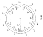
- Fig. 20 shows flutter bricks 810 and spaces 811 around the circumference of cavity 812 at radial location 815.
- flutter bricks at different radial locations, and at more than one radial location.
- Fig. 21 shows flutter bricks around the entire circumference of the cavity at each radial location, this need not be the case. Rather, the flutter bricks may occupy only part of a circumference at a radial location, as was the case in the implementation of Fig. 15 .
- each flutter brick may be a single ferromagnetic arrangement that is configured to generate a magnetic field bump having a specific size and shape.
- a single ferromagnetic arrangement may be a single contiguous or physically connected structure or it can be two vertically-aligned, but physically unconnected ferromagnetic structures (e.g., one on each yoke) separated by empty space or other material through which magnetic flux passes.
- Vertical alignment may include alignment between yokes or other magnetic structures, such as pole pieces, and includes any appropriately aligned whole or part of the ferromagnetic structures.
- the "valley" areas need not be implemented using empty spaces, but rather may be implemented using ferromagnetic structures that have a different size and/or shape than (e.g., shorter, taller, thinner, thicker, slimmer wider, etc. than) the flutter bricks and that are made of the same material, or using structures of the same or different size as the flutter bricks but that have different ferromagnetic properties than the flutter bricks. Any appropriate combination of ferromagnetic materials, non-ferromagnetic materials, active coils, and empty space may be used to produce appropriate magnetic field fluctuations to cause vertical focusing of the type described above.
- flutter bricks shown in the figures are about the same size and shape, their sizes and/or shapes may vary, either in the same radial location or in different radial locations.
- the numbers of flutter bricks per radial location may vary from radius to radius.
- the number and configuration of flutter bricks may be set as desired to produce any appropriate level(s) of vertical focusing throughout the cavity.
- the cavity may be controlled so as to reduce, or minimize, the amount of bowing (or other distortion) in the magnetic field therein.
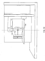
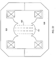
- the shape of the yokes 819 (or other magnetic structures) on surfaces that face the magnetic cavity may be as shown in Fig. 22 .
- the magnetic field lines 820 within cavity 822 are substantially straight throughout the cavity, even at the edges of the cavity (where, in other implementations, the field lines bow).
- Straight magnetic field lines have some advantages in a particle accelerator. For example, as described above, by maintaining the magnetic field lines substantially straight throughout the cavity, it is possible to reduce the radius of the cavity without a significant reduction in performance.
- Flutter may be used to provide vertical focusing in implementations where the magnetic field lines are substantially straight throughout the cavity.
- flutter bricks as shown in Figs. 15 , 20 and 21 may be incorporated, with appropriate spaces or other structures, to produce the magnetic hills and valleys used to produce flutter.
- the flutter bricks may be introduced at one or more radial locations and may, or may not, traverse an entire circumference of the cavity at each radial location.
- the regions of magnetic fluctuation e.g., the magnetic hills and valleys
- the regions of magnetic fluctuation may be produced using any one or more of the configurations described above or elsewhere herein.
- flutter may be produced using continuous regions having differing ferromagnetic properties.
- Fig. 23 shows structure 822 that may be incorporated into the resonant cavity of a particle accelerator to produce flutter and thereby vertically focus a particle beam.
- Structure 822 includes regions 824 having high magnetic field and regions 825 having low magnetic field. "High” in this context, simply means higher than the "low” magnetic field in the low magnetic field regions, and neither "high” nor "low” is meant to imply any absolute or specific values.
- each region is pie-shaped, with a focal or center point at about the center of the cavity (where the plasma column is located), although that need not be the case in all implementations.
- the edge of each pie-shaped region roughly corresponds to the outer edge of the cavity, although that need not be the case in all implementations.
- the regions of high and low magnetic field alternate and may have any of the characteristics described herein. For example, they may be ferromagnetic arrangements and empty space; they may be different materials (e.g., ferromagnetic and non-ferromagnetic); they may have different amounts of a ferromagnetic material (e.g., iron, steel, etc.), and so forth.
- the resonant (acceleration) cavity may contain a single structure 822 or multiple, vertically aligned such structures 822. In the case of multiple structures, each structure 822 may be connected to a yoke or elsewhere.
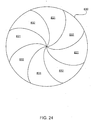
- a structure 830 that may be incorporated into the resonant cavity of a particle accelerator to produce flutter, and thereby vertically focus a particle beam, may have a pinwheel shape. All characteristics and variations associated with the pie-shaped structure 822 of Fig. 23 apply equally to the pinwheel shaped structure of Fig. 24 .
- structure 830 includes regions 831 having high magnetic field and regions 832 having low magnetic field. As above, "high” in this context, simply means higher than the "low” magnetic field in the low magnetic field regions, and neither "high” nor “low” is meant to imply any absolute or specific values.
- structures 822 and 830 may be incorporated into the implementations of Figs. 15 , 21 and 22 to produce flutter or to augment flutter produced by the flutter bricks and spaces.
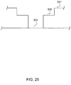
- a flutter-inducing structure may have different levels of hills and valleys.
- Fig. 25 which is a sideview of such a structure
- Second hill 837 by virtue of its height, contains more ferromagnetic material than first hill 836, which contains more ferromagnetic material than valley 835.
- Such a configuration may be incorporated into configurations like the structures of Figs. 23 and 24 , respectively.
- the flutter-inducing structure is not limited to use with two or three levels (e.g., amounts) of ferromagnetic material, but rather may incorporate any appropriate numbers of levels of ferromagnetic materials and/or different types of materials.
- the particle accelerator used in the example particle therapy systems described herein may be a variable-energy particle accelerator.
- an example treatment system 910 includes an accelerator 912, e.g., a synchrocyclotron, from which a particle (e.g., proton) beam 914 having a variable energy is extracted to irradiate a target volume 924 of a body 922.
- an accelerator 912 e.g., a synchrocyclotron
- one or more additional devices such as a scanning unit 916 or a scattering unit 916, one or more monitoring units 918, and an energy degrader 920, are placed along the irradiation direction 928.
- the devices intercept the cross-section of the extracted beam 914 and alter one or more properties of the extracted beam for the treatment.
- a target volume to be irradiated (an irradiation target) by a particle beam for treatment typically has a three-dimensional configuration.
- the target volume is divided into layers along the irradiation direction of the particle beam so that the irradiation can be done on a layer-by-layer basis.
- the penetration depth (or which layer the beam reaches) within the target volume is largely determined by the energy of the particle beam.
- a particle beam of a given energy does not reach substantially beyond a corresponding penetration depth for that energy.
- the energy of the particle beam is changed.
- the target volume 924 is divided into nine layers 926a-926i along the irradiation direction 928.
- the irradiation starts from the deepest layer 926i, one layer at a time, gradually to the shallower layers and finishes with the shallowest layer 926a.
- the energy of the particle beam 914 is controlled to be at a level to allow the particle beam to stop at a desired layer, e.g., the layer 926d, without substantially penetrating further into the body or the target volume, e.g., the layers 926e-926i or deeper into the body.
- the desired energy of the particle beam 914 decreases as the treatment layer becomes shallower relative to the particle acceleration.
- the beam energy difference for treating adjacent layers of the target volume 924 is about 3 MeV to about 100 MeV, e.g., about 10 MeV to about 80 MeV, although other differences may also be possible, depending on, e.g., the thickness of the layers and the properties of the beam.
- the energy variation for treating different layers of the target volume 924 can be performed at the accelerator 912 (e.g., the accelerator can vary the energy) so that, in some implementations, no additional energy variation is required after the particle beam is extracted from the accelerator 912. So, the optional energy degrader 920 in the treatment system 10 may be eliminated from the system.
- the accelerator 912 can output particle beams having an energy that varies between about 100 MeV and about 300 MeV, e.g., between about 115 MeV and about 250 MeV.
- the variation can be continuous or non-continuous, e.g., one step at a time.
- the variation, continuous or non-continuous can take place at a relatively high rate, e.g., up to about 50 MeV per second or up to about 20 MeV per second.
- Non-continuous variation can take place one step at a time with a step size of about 10 MeV to about 90 MeV.
- the accelerator 912 can vary the energy of the particle beam for irradiating a next layer, e.g., within several seconds or within less than one second.
- the treatment of the target volume 924 can be continued without substantial interruption or even without any interruption.
- the step size of the non-continuous energy variation is selected to correspond to the energy difference needed for irradiating two adjacent layers of the target volume 924.
- the step size can be the same as, or a fraction of, the energy difference.
- the accelerator 912 and the degrader 920 collectively vary the energy of the beam 914.
- the accelerator 912 provides a coarse adjustment and the degrader 920 provides a fine adjustment or vice versa.
- the accelerator 912 can output the particle beam that varies energy with a variation step of about 10-80 MeV, and the degrader 920 adjusts (e.g., reduces) the energy of the beam at a variation step of about 2-10 MeV.
- the reduced use (or absence) of the energy degrader helps to maintain properties and quality of the output beam from the accelerator, e.g., beam intensity.
- the control of the particle beam can be performed at the accelerator. Side effects, e.g., from neutrons generated when the particle beam passes the degrader 920 can be reduced or eliminated.
- the energy of the particle beam 914 may be adjusted to treat another target volume 930 in another body or body part 922' after completing treatment in target volume 924.
- the target volumes 924, 930 may be in the same body (or patient), or may belong to different patients. It is possible that the depth D of the target volume 930 from a surface of body 922' is different from that of the target volume 924.
- the degrader 912 may only reduce the beam energy and not increase the beam energy.
- the beam energy required for treating target volume 930 is greater than the beam energy required to treat target volume 924.
- the accelerator 912 may increase the output beam energy after treating the target volume 924 and before treating the target volume 930.
- the beam energy required for treating target volume 930 is less than the beam energy required to treat target volume 924.
- the degrader 920 can reduce the energy, the accelerator 912 can be adjusted to output a lower beam energy to reduce or eliminate the use of the degrader 920.
- the division of the target volumes 924, 930 into layers can be different or the same. And the target volume 930 can be treated similarly on a layer by layer basis to the treatment of the target volume 924.
- the treatment of the different target volumes 924, 930 on the same patient may be substantially continuous, e.g., with the stop time between the two volumes being no longer than about 30 minutes or less, e.g., 25 minutes or less, 20 minutes or less, 15 minutes or less, 10 minutes or less, 5 minutes or less, or 1 minute or less.
- the accelerator 912 can be mounted on a movable gantry and the movement of the gantry can move the accelerator to aim at different target volumes. In some situations, the accelerator 912 can complete the energy adjustment of the output beam 914 during the time the treatment system makes adjustment (such as moving the gantry) after completing the treatment of the target volume 924 and before starting treating the target volume 930.
- the treatment can begin with the adjusted, desired beam energy. Beam energy adjustment for different patients can also be completed relatively efficiently. In some examples, all adjustments, including increasing/reducing beam energy and/or moving the gantry are done within about 30 minutes, e.g., within about 25 minutes, within about 20 minutes, within about 15 minutes, within about 10 minutes or within about 5 minutes.
- an irradiation dose is applied by moving the beam across the two-dimensional surface of the layer (which is sometimes called scanning beam) using a scanning unit 916.
- the layer can be irradiated by passing the extracted beam through one or more scatterers of the scattering unit 16 (which is sometimes called scattering beam).
- Beam properties can be selected before a treatment or can be adjusted during the treatment by controlling the accelerator 912 and/or other devices, such as the scanning unit/scatterer(s) 916, the degrader 920, and others not shown in the figures.
- system 910 includes a controller 932, such as a computer, in communication with one or more devices in the system. Control can be based on results of the monitoring performed by the one or more monitors 918, e.g., monitoring of the beam intensity, dose, beam location in the target volume, etc.
- Controller 932 can also store a treatment plan for one or more target volumes (for the same patient and/or different patients).
- the treatment plan can be determined before the treatment starts and can include parameters, such as the shape of the target volume, the number of irradiation layers, the irradiation dose for each layer, the number of times each layer is irradiated, etc.
- the adjustment of a beam property within the system 910 can be performed based on the treatment plan. Additional adjustment can be made during the treatment, e.g., when deviation from the treatment plan is detected.
- the accelerator 912 is configured to vary the energy of the output particle beam by varying the magnetic field in which the particle beam is accelerated.
- one or more sets of coils receives variable electrical current to produce a variable magnetic field in the cavity.
- one set of coils receives a fixed electrical current, while one or more other sets of coils receives a variable current so that the total current received by the coil sets varies.
- all sets of coils are superconducting.
- some sets of coils, such as the set for the fixed electrical current are superconducting, while other sets of coils, such as the one or more sets for the variable current, are non-superconducting.
- all sets of coils are non-superconducting.
- the magnitude of the magnetic field is scalable with the magnitude of the electrical current. Adjusting the total electric current of the coils in a predetermined range can generate a magnetic field that varies in a corresponding, predetermined range. In some examples, a continuous adjustment of the electrical current can lead to a continuous variation of the magnetic field and a continuous variation of the output beam energy. Alternatively, when the electrical current applied to the coils is adjusted in a non-continuous, step-wise manner, the magnetic field and the output beam energy also varies accordingly in a non-continuous (step-wise) manner. The scaling of the magnetic field to the current can allow the variation of the beam energy to be carried out relatively precisely, although sometimes minor adjustment other than the input current may be performed.
- the accelerator 912 is configured to apply RF voltages that sweep over different ranges of frequencies, with each range corresponding to a different output beam energy. For example, if the accelerator 912 is configured to produce three different output beam energies, the RF voltage is capable of sweeping over three different ranges of frequencies. In another example, corresponding to continuous beam energy variations, the RF voltage sweeps over frequency ranges that continuously change. The different frequency ranges may have different lower frequency and/or upper frequency boundaries.
- the extraction channel may be configured to accommodate the range of different energies produced by the variable-energy particle accelerator. Particle beams having different energies can be extracted from the accelerator 912 without altering the features of the regenerator that is used for extracting particle beams having a single energy.
- the regenerator can be moved to disturb (e.g., change) different particle orbits in the manner described above and/or iron rods (magnetic shims) can be added or removed to change the magnetic field bump provided by the regenerator. More specifically, different particle energies will typically be at different particle orbits within the cavity.
- movement of the regenerator is performed in real-time to match real-time changes in the particle beam energy output by the accelerator.
- particle energy is adjusted on a per-treatment basis, and movement of the regenerator (and/or addition/removal of magnetic shims) is performed in advance of the treatment.
- movement of the regenerator (and/or addition/removal of magnetic shims) may be computer controlled.
- a computer may control one or more motors that effect movement of the regenerator and/or magnetic shims.
- the regenerator is implemented using one or more magnetic shims that are controllable to move to the appropriate location(s).
- structure 715 (described above) is controlled to accommodate the different energies produced by the particle accelerator. For example, structure 715 may be rotated so that an appropriate thickness intercepts a particle beam having a particular energy. Structure 715 thus absorbs at least some of the energy in the particle beam, enabling the particle beam to traverse the extraction channel, as described above.
- table 1 shows three example energy levels at which example accelerator 912 can output particle beams.
- the corresponding parameters for producing the three energy levels are also listed.
- the magnet current refers to the total electrical current applied to the one or more coil sets in the accelerator 912; the maximum and minimum frequencies define the ranges in which the RF voltage sweeps; and "r" is the radial distance of a location to a center of the cavity in which the particles are accelerated. Table 1. Examples of beam energies and respective parameters.
- the accelerator can be a synchrocyclotron and the particles may be protons.
- the particles output as pulsed beams.
- the energy of the beam output from the particle accelerator can be varied during the treatment of one target volume in a patient, or between treatments of different target volumes of the same patient or different patients.
- settings of the accelerator are changed to vary the beam energy when no beam (or particles) is output from the accelerator.
- the energy variation can be continuous or non-continuous over a desired range.
- the particle accelerator (synchrocyclotron 502), which may be a variable-energy particle accelerator like accelerator 912 described above, may be configured to particle beams that have a variable energy.
- the range of the variable energy can have an upper boundary that is about 200 MeV to about 300 MeV or higher, e.g., 200 MeV, about 205 MeV, about 210 MeV, about 215 MeV, about 220 MeV, about 225 MeV, about 230 MeV, about 235 MeV, about 240 MeV, about 245 MeV, about 250 MeV, about 255 MeV, about 260 MeV, about 265 MeV, about 270 MeV, about 275 MeV, about 280 MeV, about 285 MeV, about 290 MeV, about 295 MeV, or about 300 MeV or higher.
- the range can also have a lower boundary that is about 100 MeV or lower to about 200 MeV, e.g., about 100 MeV or lower, about 105 MeV, about 110 MeV, about 115 MeV, about 120 MeV, about 125 MeV, about 130 MeV, about 135 MeV, about 140 MeV, about 145 MeV, about 150 MeV, about 155 MeV, about 160 MeV, about 165 MeV, about 170 MeV, about 175 MeV, about 180 MeV, about 185 MeV, about 190 MeV, about 195 MeV, about 200 MeV.
- a lower boundary that is about 100 MeV or lower to about 200 MeV, e.g., about 100 MeV or lower, about 105 MeV, about 110 MeV, about 115 MeV, about 120 MeV, about 125 MeV, about 130 MeV, about 135 MeV, about 140 MeV, about 145 MeV, about 150 MeV, about 155 MeV, about 160 MeV, about 165 MeV, about
- the variation is non-continuous and the variation step can have a size of about 10 MeV or lower, about 15 MeV, about 20 MeV, about 25 MeV, about 30 MeV, about 35 MeV, about 40 MeV, about 45 MeV, about 50 MeV, about 55 MeV, about 60 MeV, about 65 MeV, about 70 MeV, about 75 MeV, or about 80 MeV or higher.
- Varying the energy by one step size can take no more than 30 minutes, e.g., about 25 minutes or less, about 20 minutes or less, about 15 minutes or less, about 10 minutes or less, about 5 minutes or less, about 1 minute or less, or about 30 seconds or less.
- the variation is continuous and the accelerator can adjust the energy of the particle beam at a relatively high rate, e.g., up to about 50 MeV per second, up to about 45 MeV per second, up to about 40 MeV per second, up to about 35 MeV per second, up to about 30 MeV per second, up to about 25 MeV per second, up to about 20 MeV per second, up to about 15 MeV per second, or up to about 10 MeV per second.
- the accelerator can be configured to adjust the particle energy both continuously and non-continuously.
- a combination of the continuous and non-continuous variation can be used in a treatment of one target volume or in treatments of different target volumes. Flexible treatment planning and flexible treatment can be achieved.
- a particle accelerator that outputs a particle beam having a variable energy can provide accuracy in irradiation treatment and reduce the number of additional devices (other than the accelerator) used for the treatment. For example, the use of degraders for changing the energy of an output particle beam may be reduced or eliminated.
- the properties of the particle beam, such as intensity, focus, etc. can be controlled at the particle accelerator and the particle beam can reach the target volume without substantial disturbance from the additional devices.
- the relatively high variation rate of the beam energy can reduce treatment time and allow for efficient use of the treatment system.
- the accelerator such as the synchrocyclotron 502 of Fig. 1 , accelerates particles or particle beams to variable energy levels by varying the magnetic field in the accelerator, which can be achieved by varying the electrical current applied to coils for generating the magnetic field.
- example synchrocyclotron 10 (502 in Fig. 1 ) includes a magnet system that contains a particle source 90, a radiofrequency drive system 91, and a beam extraction system 38.
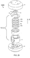
- Fig. 29 shows an example of a magnet system that may be used in a variable-energy accelerator.
- the magnetic field established by the magnet system 1012 can vary by about 5% to about 35 % of a maximum value of the magnetic field that two sets of coils 40a and 40b, and 42a and 42b are capable of generating.
- the magnetic field established by the magnet system has a shape appropriate to maintain focus of a contained proton beam using a combination of the two sets of coils and a pair of shaped ferromagnetic (e.g., low carbon steel) structures, examples of which are provided above.
- Each set of coils may be a split pair of annular coils to receive electrical current.
- both sets of coils are superconducting.
- only one set of the coils is superconducting and the other set is non-superconducting or normal conducting (also discussed further below). It is also possible that both sets of coils are non-superconducting.
- Suitable superconducting materials for use in the coils include niobium-3 tin (Nb3Sn) and/or niobium-titanium.
- Other normal conducting materials can include copper. Examples of the coil set constructions are described further below.
- the two sets of coils can be electrically connected serially or in parallel.
- the total electrical current received by the two sets of coils can include about 2 million ampere turns to about 10 million ampere turns, e.g., about 2.5 to about 7.5 million ampere turns or about 3.75 million ampere turns to about 5 million ampere turns.
- one set of coils is configured to receive a fixed (or constant) portion of the total variable electrical current, while the other set of coils is configured to receive a variable portion of the total electrical current.
- the total electrical current of the two coil sets varies with the variation of the current in one coil set. In other situations, the electrical current applied to both sets of coils can vary.
- the variable total current in the two sets of coils can generate a magnetic field having a variable magnitude, which in turn varies the acceleration pathways of the particles and produces particles having variable energies.
- the magnitude of the magnetic field generated by the coil(s) is scalable to the magnitude of the total electrical current applied to the coil(s). Based on the scalability, in some implementations, linear variation of the magnetic field strength can be achieved by linearly changing the total current of the coil sets. The total current can be adjusted at a relatively high rate that leads to a relatively high-rate adjustment of the magnetic field and the beam energy.
- the ratio between values of the current and the magnetic field at the geometric center of the coil rings is: 1990:8.7 (approximately 228.7:1); 1920:8.4 (approximately 228.6:1); 1760:7.9 (approximately 222.8:1). Accordingly, adjusting the magnitude of the total current applied to a superconducting coil(s) can proportionally (based on the ratio) adjust the magnitude of the magnetic field.
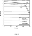
- the scalability of the magnetic field to the total electrical current in the example of Table 1 is also shown in the plot of Fig. 27 , where BZ is the magnetic field along the Z direction; and R is the radial distance measured from a geometric center of the coil rings along a direction perpendicular to the Z direction.
- the magnetic field has the highest value at the geometric center, and decreases as the distance R increases.
- the curves 1035, 1037 represent the magnetic field generated by the same coil sets receiving different total electrical current: 1760 Amperes and 1990 Amperes, respectively.
- the corresponding energies of the extracted particles are 211 MeV and 250 MeV, respectively.
- the two curves 1035, 1037 have substantially the same shape and the different parts of the curves 1035, 1037 are substantially parallel. As a result, either the curve 1035 or the curve 1037 can be linearly shifted to substantially match the other curve, indicating that the magnetic field is scalable to the total electrical current applied to the coil sets.
- the scalability of the magnetic field to the total electrical current may not be perfect.
- the ratio between the magnetic field and the current calculated based on the example shown in table 1 is not constant.
- the linear shift of one curve may not perfectly match the other curve.
- the total current is applied to the coil sets under the assumption of perfect scalability.
- the target magnetic field (under the assumption of perfect scalability) can be generated by additionally altering the features, e.g., geometry, of the coils to counteract the imperfection in the scalability.
- ferromagnetic rods can be inserted or removed from one or both of the magnetic structures.
- the features of the coils can be altered at a relatively high rate so that the rate of the magnetic field adjustment is not substantially affected as compared to the situation in which the scalability is perfect and only the electrical current needs to be adjusted.
- the rods can be added or removed at the time scale of seconds or minutes, e.g., within 5 minutes, within 1 minute, less than 30 seconds, or less than 1 second.
- settings of the accelerator such as the current applied to the coil sets, can be chosen based on the substantial scalability of the magnetic field to the total electrical current in the coil sets.
- the coil set 42a, 42b can be configured to receive a fixed electrical current corresponding to a lower boundary of a desired range of the magnetic field.
- the fixed electrical current is 1760 Amperes.
- the coil set 40a, 40b can be configured to receive a variable electrical current having an upper boundary corresponding to a difference between an upper boundary and a lower boundary of the desired range of the magnetic field.
- the coil set 40a, 40b is configured to receive electrical current that varies between 0 Ampere and 230 Amperes.
- the coil set 42a, 42b can be configured to receive a fixed electrical current corresponding to an upper boundary of a desired range of the magnetic field.
- the fixed current is 1990 Amperes.
- the coil set 40a, 40b can be configured to receive a variable electrical current having an upper boundary corresponding to a difference between a lower boundary and an upper boundary of the desired range of the magnetic field.
- the coil set 40a, 40b is configured to receive electrical current that varies between -230 Ampere and 0 Ampere.
- the total variable magnetic field generated by the variable total current for accelerating the particles can have a maximum magnitude greater than 4 Tesla, e.g., greater than 5 Tesla, greater than 6 Tesla, greater than 7 Tesla, greater than 8 Tesla, greater than 9 Tesla, or greater than 10 Tesla, and up to about 20 Tesla or higher,-e.g., up to about 18 Tesla, up to about 15 Tesla, or up to about 12 Tesla.
- variation of the total current in the coil sets can vary the magnetic field by about 0.2 Tesla to about 4.2 Tesla or more, e.g., about 0.2 Tesla to about 1.4 Tesla or about 0.6 Tesla to about 4.2 Tesla.
- the amount of variation of the magnetic field can be proportional to the maximum magnitude.
- Fig. 28 shows an example RF structure for sweeping the voltage on the dee plate 100 over an RF frequency range for each energy level of the particle beam, and for varying the frequency range when the particle beam energy is varied.
- the semicircular surfaces 103, 105 of the dee plate 100 are connected to an inner conductor 1300 and housed in an outer conductor 1302.
- the high voltage is applied to the dee plate 100 from a power source (not shown, e.g., an oscillating voltage input) through a power coupling device 1304 that couples the power source to the inner conductor.
- the coupling device 1304 is positioned on the inner conductor 1300 to provide power transfer from the power source to the dee plate 100.
- the dee plate 100 is coupled to variable reactive elements 1306, 1308 to perform the RF frequency sweep for each particle energy level, and to change the RF frequency range for different particle energy levels.
- the variable reactive element 1306 can be a rotating capacitor that has multiple blades 1310 rotatable by a motor (not shown). By meshing or unmeshing the blades 1310 during each cycle of RF sweeping, the capacitance of the RF structure changes, which in turn changes the resonant frequency of the RF structure. In some implementations, during each quarter cycle of the motor, the blades 1310 mesh with the each other. The capacitance of the RF structure increases and the resonant frequency decreases. The process reverses as the blades 1310 unmesh. As a result, the power required to generate the high voltage applied to the dee plate 103 and necessary to accelerate the beam can be reduced by a large factor. In some implementations, the shape of the blades 1310 is machined to form the required dependence of resonant frequency on time.
- the RF frequency generation is synchronized with the blade rotation by sensing the phase of the RF voltage in the resonator, keeping the alternating voltage on the dee plates close to the resonant frequency of the RF cavity. (The dummy dee is grounded and is not shown in Fig. 28 ).
- the variable reactive element 1308 can be a capacitor formed by a plate 1312 and a surface 1316 of the inner conductor 1300.
- the plate 1312 is movable along a direction 1314 towards or away from the surface 1316.
- the capacitance of the capacitor changes as the distance D between the plate 1312 and the surface 1316 changes. For each frequency range to be swept for one particle energy, the distance D is at a set value, and to change the frequency range, the plate 1312 is moved corresponding to the change in the energy of the output beam.
- the inner and outer conductors 1300, 1302 are formed of a metallic material, such as copper, aluminum, or silver.
- the blades 1310 and the plate 1312 can also be formed of the same or different metallic materials as the conductors 1300, 1302.
- the coupling device 1304 can be an electrical conductor.
- the variable reactive elements 1306, 1308 can have other forms and can couple to the dee plate 100 in other ways to perform the RF frequency sweep and the frequency range alteration.
- a single variable reactive element can be configured to perform the functions of both the variable reactive elements 1306, 1308. In other implementations, more than two variable reactive elements can be used.
- variable-energy particle accelerator any of the features described herein may be configured for use with a variable-energy particle accelerator, such as that described above.
- variable-energy particle accelerator any of the features described herein may be configured for use with a variable-energy particle accelerator, such as that described above.
- any two more of the foregoing implementations may be used in an appropriate combination in an appropriate particle accelerator (e.g., a synchrocyclotron).
- an appropriate particle accelerator e.g., a synchrocyclotron
- individual features of any two more of the foregoing implementations may be used in an appropriate combination.
- the example implementations described herein are not limited to use with a particle therapy system or to use with the example particle therapy systems described herein. Rather, the example implementations can be used in any appropriate system that directs accelerated particles to an output.
- Provisional Application entitled “MAGNETIC FIELD REGENERATOR” (Application No. 61/707,590 ), the U.S. Provisional Application entitled “FOCUSING A PARTICLE BEAM” (Application No. 61/707,704 ), the U.S. Provisional Application entitled “CONTROLLING PARTICLE THERAPY (Application No. 61/707,624 ), and the U.S. Provisional Application entitled “CONTROL SYSTEM FOR A PARTICLE ACCELERATOR” (Application No. 61/707,645 ).
- Patent Application No. 11/937,573 filed on November 9, 2007 U.S. Patent Application No. 11/187,633 , titled “A Programmable Radio Frequency Waveform Generator for a Synchrocyclotron," filed July 21, 2005, U.S. Provisional Application No. 60/590,089, filed on July 21, 2004 , U.S. Patent Application No. 10/949,734 , titled “A Programmable Particle Scatterer for Radiation Therapy Beam Formation", filed September 24, 2004, and U.S. Provisional Application No.60/590,088, filed July 21, 2005 .
- Provisional Application entitled “MAGNETIC FIELD REGENERATOR” (Application No. 61/707,590 ), the U.S. Provisional Application entitled “FOCUSING A PARTICLE BEAM” (Application No. 61/707,704 ), the U.S. Provisional Application entitled “CONTROLLING PARTICLE THERAPY (Application No. 61/707,624 ), and the U.S. Provisional Application entitled “CONTROL SYSTEM FOR A PARTICLE ACCELERATOR” (Application No. 61/707,645 ), U.S. Patent No. 7,728,311 which issued on June 1, 2010 , U.S. Patent Application No.
Landscapes
- Engineering & Computer Science (AREA)
- Physics & Mathematics (AREA)
- Plasma & Fusion (AREA)
- Spectroscopy & Molecular Physics (AREA)
- Health & Medical Sciences (AREA)
- Biomedical Technology (AREA)
- Nuclear Medicine, Radiotherapy & Molecular Imaging (AREA)
- Pathology (AREA)
- Radiology & Medical Imaging (AREA)
- Life Sciences & Earth Sciences (AREA)
- Animal Behavior & Ethology (AREA)
- General Health & Medical Sciences (AREA)
- Public Health (AREA)
- Veterinary Medicine (AREA)
- Optics & Photonics (AREA)
- Particle Accelerators (AREA)
- Radiation-Therapy Devices (AREA)
- Plasma Technology (AREA)
Claims (19)
- Ein Teilchenbeschleuniger (502) umfassend:einen Hohlraum (700), welcher einem Magnetfeld ausgesetzt ist;eine Plasmasäule, welche sich ungefähr im Zentrum des Hohlraums befindet, eine Spannungsquelle, um eine Radiofrequenzspannung im Hohlraum durchzulaufen, um Teilchen aus der Plasmasäule zu beschleunigen, wobei das Magnetfeld bewirkt, dass Teilchen, welche aus der Plasmasäule beschleunigt werden, sich umlaufend innerhalb des Hohlraums bewegen, wobei das Magnetfeld einen Fluss aufweist, welcher sich an Rändern des Hohlraums verbiegt, oder wobei das Magnetfeld einen Fluss aufweist, welcher im Wesentlichen gerade durch den Hohlraum verläuft;einen Regenerator (702), welcher ausgelegt ist, um eine erste Magnetfelddelle innerhalb des Hohlraums (700) bereitzustellen, um dadurch aufeinanderfolgende Umlaufbahnen der aus der Plasmasäule beschleunigte Teilchen so zu ändern, dass die Teilchen schließlich zu einem Extraktionspunkt ausgegeben werden, wobei der Regenerator an einem Radius im Hohlraum relativ zur Plasmasäule angeordnet ist; undgekennzeichnet durch ferromagnetische Anordnungen (810), welche im Hohlraum (700) in der Nähe des Radius und auf beiden Umfangsseiten des Regenerators an ungefähr den gleichen radialen Orten angeordnet sind, wobei jede ferromagnetische Anordnung eine zweite Magnetfelddelle erzeugt, wobei die ferromagnetischen Anordnungen, welche an dem Regenerator angrenzen, durch einen Leerraum (811) vom Regenerator getrennt sind, wobei eine Kombination aus dem Leerraum, dem Regenerator und der ferromagnetischen Anordnungen angeordnet ist, um Magnetfeldschwankungen zu erzeugen, welche eine Komponente in einem Winkel zu einer Teilchen-Umlaufbahn aufweist, um mindestens einem Teil einer senkrecht sich bündelnden Reduktion, welche durch die erste Magnetfelddelle verursacht wird, entgegen zu wirken.
- Der Teilchenbeschleuniger nach Anspruch 1, wobei das Magnetfeld mindestens 4 Tesla ist und die erste Magnetfelddelle, welche von dem Regenerator produziert wird, höchstens 2 Tesla ist.
- Der Teilchenbeschleuniger nach Anspruch 1, wobei nur zwei ferromagnetische Anordnungen vorhanden sind, eine auf jeder Umfangsseite des Regenerators.
- Der Teilchenbeschleuniger nach Anspruch 1, wobei mehr als zwei ferromagnetische Anordnungen in einem gleichen Radius relativ zur Plasmasäule vorhanden sind.
- Der Teilchenbeschleuniger nach Anspruch 1, wobei mehrere ferromagnetischen Anordnungen in jedem der mehreren Radien relativ zur Plasmasäule vorhanden sind.
- Der Teilchenbeschleuniger nach Anspruch 1, wobei die ferromagnetischen Anordnungen ausgelegt sind, um eine Magnetfeldschwankung zu produzieren, welche eine azimutal gemittelte fraktional normalisierte Magnetfeldvarianz umfasst, welche zwischen 0,25% und 20% liegt.
- Ein Teilchenbeschleuniger nach irgendeinem der Ansprüche 1-6, zweite Alternative, wobei der Hohlraum alternierenden Regionen (824, 825, 831, 832, 835, 836, 837) des ersten Magnetfeldes und des zweiten Magnetfeldes ausgesetzt ist, wobei das erste Magnetfeld unterschiedlich zum zweiten Magnetfeld ist, und die zwei Felder angeordnet sind, um magnetische Fluktuationen zu erzeugen, welche eine Komponente, welche im Wesentlichen rechtwinklig zu den Umlaufbahnen der Teilchen innerhalb des Hohlraums ist, aufweisen.
- Der Teilchenbeschleuniger nach Anspruch 7, wobei die alternierenden Regionen verschiedene Ebenen aus ferromagnetischem Material aufweisen.
- Der Teilchenbeschleuniger nach Anspruch 7, wobei die alternierenden Regionen Regionen aus ferromagnetischem Material und Regionen, in denen das ferromagnetische Material abwesend ist, umfassen.
- Der Teilchenbeschleuniger nach Anspruch 7, wobei die alternierenden Regionen (824, 825) kuchenförmig sind, wobei jede einen Punkt an der Plasmasäule und einen Rand an einem Rand des Hohlraums aufweist.
- Der Teilchenbeschleuniger nach Anspruch 8, wobei die alternierenden Regionen Nadelradformen (831, 832) aufweisen, wobei jede einen Punkt an der Plasmasäule und einen Rand an einem Rand des Hohlraums aufweist.
- Der Teilchenbeschleuniger nach Anspruch 7, wobei der Hohlraum durch zwei magnetische Strukturen definiert ist; und wobei die alternierenden Regionen senkrecht angeordnete alternierenden Regionen (822) umfassen, wobei eine mit der ersten magnetischen Struktur, und die andere mit der zweiten magnetischen Struktur verbunden ist.
- Der Teilchenbeschleuniger nach Anspruch 7, wobei die magnetischen Fluktuationen Teilchen, welche sich im Hohlraum in Umlaufbahnen befinden, senkrecht bündeln.
- Der Teilchenbeschleuniger nach Anspruch 7, wobei die alternierenden Regionen des ersten Magnetfeldes und des zweiten Magnetfeldes angeordnet sind, um eine Magnetfeldschwankung zu erzeugen, welche eine azimutal gemittelte fraktional normalisierte Magnetfeldvarianz umfasst, welche zwischen 0,25% und 20% liegt.
- Der Teilchenbeschleuniger nach Anspruch 1 oder 7, wobei der Teilchenbeschleuniger ein Synchrozyklotron (910) ist.
- Ein Protontherapiesystem umfassend:den Teilchenbeschleuniger nach Anspruch 1 oder 7; undeine Gantry (605) auf welche der Teilchenbeschleuniger montiert ist, wobei die Gantry relativ zu einer Patientenposition rotierbar ist;wobei das System ausgelegt ist, um Protonen in Wesentlichen direkt aus dem Teilchenbeschleuniger an die Patientenposition auszugeben.
- Das Protontherapiesystem nach Anspruch 16, wobei der Teilchenbeschleuniger ein Synchrozyklotron (910) umfasst.
- Das Protontherapiesystem nach Anspruch 17, wobei das Magnetfeld 4 Tesla oder mehr ist, und wobei das Synchrozyklotron einen Teilchenbeschleuniger mit variabler Energie ist.
- Der Teilchenbeschleuniger nach Anspruch 1 oder 8, weiter umfassend:
magnetische Strukturen, welche den Hohlraum definieren, in welchem die Teilchen beschleunigt werden, wobei die Teilchen als Teilchenstrahl (914) ausgegeben werden, welcher eine aus einem Bereich an Energien ausgewählte Energie aufweist.
Applications Claiming Priority (2)
| Application Number | Priority Date | Filing Date | Title |
|---|---|---|---|
| US201261707572P | 2012-09-28 | 2012-09-28 | |
| PCT/US2013/062120 WO2014052722A2 (en) | 2012-09-28 | 2013-09-27 | Focusing a particle beam using magnetic field flutter |
Publications (2)
| Publication Number | Publication Date |
|---|---|
| EP2901820A2 EP2901820A2 (de) | 2015-08-05 |
| EP2901820B1 true EP2901820B1 (de) | 2021-02-17 |
Family
ID=49488649
Family Applications (1)
| Application Number | Title | Priority Date | Filing Date |
|---|---|---|---|
| EP13783421.4A Active EP2901820B1 (de) | 2012-09-28 | 2013-09-27 | Fokussierung eines partikelstrahls unter verwendung eines magnetfeldflimmerns |
Country Status (6)
| Country | Link |
|---|---|
| US (1) | US9155186B2 (de) |
| EP (1) | EP2901820B1 (de) |
| JP (2) | JP6254600B2 (de) |
| CN (1) | CN104813747B (de) |
| TW (1) | TWI604868B (de) |
| WO (1) | WO2014052722A2 (de) |
Families Citing this family (34)
| Publication number | Priority date | Publication date | Assignee | Title |
|---|---|---|---|---|
| EP3557956A1 (de) | 2004-07-21 | 2019-10-23 | Mevion Medical Systems, Inc. | Programmierbarer funkfrequenzwellenformgenerator für ein synchrozyklotron |
| ES2730108T3 (es) * | 2005-11-18 | 2019-11-08 | Mevion Medical Systems Inc | Radioterapia de partículas cargadas |
| TW201422278A (zh) | 2012-09-28 | 2014-06-16 | Mevion Medical Systems Inc | 粒子加速器之控制系統 |
| EP2901824B1 (de) | 2012-09-28 | 2020-04-15 | Mevion Medical Systems, Inc. | Magnetischer ausgleichskörper zur einstellung einer position einer hauptspule und entsprechendes verfahren |
| EP2901821B1 (de) | 2012-09-28 | 2020-07-08 | Mevion Medical Systems, Inc. | Magnetfeldregenerator |
| JP6121545B2 (ja) | 2012-09-28 | 2017-04-26 | メビオン・メディカル・システムズ・インコーポレーテッド | 粒子ビームのエネルギーの調整 |
| EP2900326B1 (de) | 2012-09-28 | 2019-05-01 | Mevion Medical Systems, Inc. | Steuerung einer partikeltherapie |
| CN104813747B (zh) | 2012-09-28 | 2018-02-02 | 梅维昂医疗系统股份有限公司 | 使用磁场颤振聚焦粒子束 |
| US10254739B2 (en) | 2012-09-28 | 2019-04-09 | Mevion Medical Systems, Inc. | Coil positioning system |
| EP2901823B1 (de) | 2012-09-28 | 2021-12-08 | Mevion Medical Systems, Inc. | Steuerung der intensität eines partikelstrahls |
| EP3049151B1 (de) | 2013-09-27 | 2019-12-25 | Mevion Medical Systems, Inc. | Teilchenstrahlabtastung |
| US9962560B2 (en) | 2013-12-20 | 2018-05-08 | Mevion Medical Systems, Inc. | Collimator and energy degrader |
| US10675487B2 (en) | 2013-12-20 | 2020-06-09 | Mevion Medical Systems, Inc. | Energy degrader enabling high-speed energy switching |
| US9661736B2 (en) | 2014-02-20 | 2017-05-23 | Mevion Medical Systems, Inc. | Scanning system for a particle therapy system |
| CN103870999A (zh) * | 2014-02-25 | 2014-06-18 | 国家电网公司 | 一种基于旋转经验正交分解的辐照度区域划分方法 |
| DE102014003536A1 (de) * | 2014-03-13 | 2015-09-17 | Forschungszentrum Jülich GmbH Fachbereich Patente | Supraleitender Magnetfeldstabilisator |
| JP6452721B2 (ja) * | 2014-12-08 | 2019-01-16 | 株式会社日立製作所 | 加速器及び粒子線照射装置 |
| JP6441508B2 (ja) * | 2015-05-26 | 2018-12-19 | アンタヤ サイエンス アンド テクノロジーAntaya Science & Technology | 超伝導フラッタコイル及び非磁性補強を有する等時性サイクロトロン |
| US10786689B2 (en) | 2015-11-10 | 2020-09-29 | Mevion Medical Systems, Inc. | Adaptive aperture |
| US10211021B2 (en) * | 2016-04-11 | 2019-02-19 | Kla-Tencor Corporation | Permanent-magnet particle beam apparatus and method incorporating a non-magnetic metal portion for tunability |
| US10925147B2 (en) | 2016-07-08 | 2021-02-16 | Mevion Medical Systems, Inc. | Treatment planning |
| US11103730B2 (en) | 2017-02-23 | 2021-08-31 | Mevion Medical Systems, Inc. | Automated treatment in particle therapy |
| JP6739393B2 (ja) * | 2017-04-18 | 2020-08-12 | 株式会社日立製作所 | 粒子線加速器および粒子線治療装置 |
| WO2018201279A1 (zh) * | 2017-05-02 | 2018-11-08 | 中国科学院合肥物质科学研究院 | 超导二极磁体结构、输运装置和医疗设备 |
| JP6940676B2 (ja) | 2017-06-30 | 2021-09-29 | メビオン・メディカル・システムズ・インコーポレーテッド | リニアモーターを使用して制御される構成可能コリメータ |
| JP7057643B2 (ja) * | 2017-10-30 | 2022-04-20 | 株式会社日立製作所 | 粒子線治療システム |
| WO2019123617A1 (ja) * | 2017-12-21 | 2019-06-27 | 三菱電機株式会社 | 加速器及び粒子線治療装置 |
| JP2019200899A (ja) | 2018-05-16 | 2019-11-21 | 株式会社日立製作所 | 粒子線加速器および粒子線治療システム |
| CN108551717B (zh) * | 2018-06-04 | 2020-04-28 | 合肥中科离子医学技术装备有限公司 | 一种回旋加速器中心区增强轴向聚焦的方法 |
| EP3934751B1 (de) | 2019-03-08 | 2024-07-17 | Mevion Medical Systems, Inc. | Kollimator und energieabbau für ein teilchentherapiesystem |
| US11570880B2 (en) * | 2020-04-02 | 2023-01-31 | Varian Medical Systems Particle Therapy Gmbh | Isochronous cyclotrons employing magnetic field concentrating or guiding sectors |
| CN111556642A (zh) * | 2020-05-13 | 2020-08-18 | 山东省肿瘤防治研究院(山东省肿瘤医院) | 一种加速器磁场调节装置、方法及加速器 |
| JP2024511277A (ja) | 2021-02-19 | 2024-03-13 | メビオン・メディカル・システムズ・インコーポレーテッド | 粒子線治療システムのためのガントリー |
| CN121365416B (zh) * | 2025-12-22 | 2026-03-06 | 福建睿斯科医疗技术有限公司 | 一种回旋加速器闭合轨道分析方法 |
Family Cites Families (557)
| Publication number | Priority date | Publication date | Assignee | Title |
|---|---|---|---|---|
| US498915A (en) | 1893-06-06 | heiminn | ||
| US2280606A (en) | 1940-01-26 | 1942-04-21 | Rca Corp | Electronic reactance circuits |
| US2615129A (en) | 1947-05-16 | 1952-10-21 | Edwin M Mcmillan | Synchro-cyclotron |
| US2492324A (en) | 1947-12-24 | 1949-12-27 | Collins Radio Co | Cyclotron oscillator system |
| US2616042A (en) | 1950-05-17 | 1952-10-28 | Weeks Robert Ray | Stabilizer arrangement for cyclotrons and the like |
| US2659000A (en) | 1951-04-27 | 1953-11-10 | Collins Radio Co | Variable frequency cyclotron |
| US2701304A (en) | 1951-05-31 | 1955-02-01 | Gen Electric | Cyclotron |
| US2812463A (en) * | 1951-10-05 | 1957-11-05 | Lee C Teng | Magnetic regenerative deflector for cyclotrons |
| US2789222A (en) | 1954-07-21 | 1957-04-16 | Marvin D Martin | Frequency modulation system |
| US2958327A (en) | 1957-03-29 | 1960-11-01 | Gladys W Geissmann | Foundation garment |
| NL235411A (de) * | 1959-01-23 | |||
| US3360647A (en) | 1964-09-14 | 1967-12-26 | Varian Associates | Electron accelerator with specific deflecting magnet structure and x-ray target |
| US3175131A (en) | 1961-02-08 | 1965-03-23 | Richard J Burleigh | Magnet construction for a variable energy cyclotron |
| US3432721A (en) | 1966-01-17 | 1969-03-11 | Gen Electric | Beam plasma high frequency wave generating system |
| JPS4323267Y1 (de) | 1966-10-11 | 1968-10-01 | ||
| NL7007871A (de) | 1970-05-29 | 1971-12-01 | ||
| FR2109273A5 (de) * | 1970-10-09 | 1972-05-26 | Thomson Csf | |
| US3679899A (en) | 1971-04-16 | 1972-07-25 | Nasa | Nondispersive gas analyzing method and apparatus wherein radiation is serially passed through a reference and unknown gas |
| US3757118A (en) | 1972-02-22 | 1973-09-04 | Ca Atomic Energy Ltd | Electron beam therapy unit |
| CA966893A (en) | 1973-06-19 | 1975-04-29 | Her Majesty In Right Of Canada As Represented By Atomic Energy Of Canada Limited | Superconducting cyclotron |
| US4047068A (en) | 1973-11-26 | 1977-09-06 | Kreidl Chemico Physical K.G. | Synchronous plasma packet accelerator |
| US3992625A (en) | 1973-12-27 | 1976-11-16 | Jersey Nuclear-Avco Isotopes, Inc. | Method and apparatus for extracting ions from a partially ionized plasma using a magnetic field gradient |
| US3886367A (en) | 1974-01-18 | 1975-05-27 | Us Energy | Ion-beam mask for cancer patient therapy |
| US3958327A (en) | 1974-05-01 | 1976-05-25 | Airco, Inc. | Stabilized high-field superconductor |
| US4129784A (en) | 1974-06-14 | 1978-12-12 | Siemens Aktiengesellschaft | Gamma camera |
| US3925676A (en) | 1974-07-31 | 1975-12-09 | Ca Atomic Energy Ltd | Superconducting cyclotron neutron source for therapy |
| US3955089A (en) | 1974-10-21 | 1976-05-04 | Varian Associates | Automatic steering of a high velocity beam of charged particles |
| CA1008125A (en) * | 1975-03-07 | 1977-04-05 | Her Majesty In Right Of Canada As Represented By Atomic Energy Of Canada Limited | Method and apparatus for magnetic field shimming in an isochronous cyclotron |
| US4230129A (en) | 1975-07-11 | 1980-10-28 | Leveen Harry H | Radio frequency, electromagnetic radiation device having orbital mount |
| ZA757266B (en) | 1975-11-19 | 1977-09-28 | W Rautenbach | Cyclotron and neutron therapy installation incorporating such a cyclotron |
| SU569635A1 (ru) | 1976-03-01 | 1977-08-25 | Предприятие П/Я М-5649 | Магнитный сплав |
| US4038622A (en) | 1976-04-13 | 1977-07-26 | The United States Of America As Represented By The United States Energy Research And Development Administration | Superconducting dipole electromagnet |
| US4112306A (en) | 1976-12-06 | 1978-09-05 | Varian Associates, Inc. | Neutron irradiation therapy machine |
| DE2754791A1 (de) | 1976-12-13 | 1978-10-26 | Varian Associates | Rennbahn-mikrotron |
| DE2759073C3 (de) | 1977-12-30 | 1981-10-22 | Siemens AG, 1000 Berlin und 8000 München | Elektronentubus |
| GB2015821B (en) | 1978-02-28 | 1982-03-31 | Radiation Dynamics Ltd | Racetrack linear accelerators |
| US4197510A (en) | 1978-06-23 | 1980-04-08 | The United States Of America As Represented By The Secretary Of The Navy | Isochronous cyclotron |
| JPS5924520B2 (ja) | 1979-03-07 | 1984-06-09 | 理化学研究所 | 等時性サイクロトロンの磁極の構造とそれの使用方法 |
| FR2458201A1 (fr) | 1979-05-31 | 1980-12-26 | Cgr Mev | Systeme resonnant micro-onde a double frequence de resonance et cyclotron muni d'un tel systeme |
| DE2926873A1 (de) | 1979-07-03 | 1981-01-22 | Siemens Ag | Strahlentherapiegeraet mit zwei lichtvisieren |
| US4293772A (en) | 1980-03-31 | 1981-10-06 | Siemens Medical Laboratories, Inc. | Wobbling device for a charged particle accelerator |
| US4342060A (en) | 1980-05-22 | 1982-07-27 | Siemens Medical Laboratories, Inc. | Energy interlock system for a linear accelerator |
| US4336505A (en) | 1980-07-14 | 1982-06-22 | John Fluke Mfg. Co., Inc. | Controlled frequency signal source apparatus including a feedback path for the reduction of phase noise |
| JPS57162527U (de) | 1981-04-07 | 1982-10-13 | ||
| US4425506A (en) | 1981-11-19 | 1984-01-10 | Varian Associates, Inc. | Stepped gap achromatic bending magnet |
| DE3148100A1 (de) | 1981-12-04 | 1983-06-09 | Uwe Hanno Dr. 8050 Freising Trinks | "synchrotron-roentgenstrahlungsquelle" |
| US4507616A (en) | 1982-03-08 | 1985-03-26 | Board Of Trustees Operating Michigan State University | Rotatable superconducting cyclotron adapted for medical use |
| JPS58141000U (ja) | 1982-03-15 | 1983-09-22 | 和泉鉄工株式会社 | 上下反転積込排出装置 |
| US4490616A (en) | 1982-09-30 | 1984-12-25 | Cipollina John J | Cephalometric shield |
| JPS5964069A (ja) | 1982-10-04 | 1984-04-11 | バリアン・アソシエイツ・インコ−ポレイテツド | 電子アーク治療用視準装置のための遮蔽物保持装置 |
| US4507614A (en) | 1983-03-21 | 1985-03-26 | The United States Of America As Represented By The United States Department Of Energy | Electrostatic wire for stabilizing a charged particle beam |
| SE462013B (sv) | 1984-01-26 | 1990-04-30 | Kjell Olov Torgny Lindstroem | Behandlingsbord foer radioterapi av patienter |
| FR2560421B1 (fr) | 1984-02-28 | 1988-06-17 | Commissariat Energie Atomique | Dispositif de refroidissement de bobinages supraconducteurs |
| US4865284A (en) | 1984-03-13 | 1989-09-12 | Siemens Gammasonics, Inc. | Collimator storage device in particular a collimator cart |
| US4641104A (en) | 1984-04-26 | 1987-02-03 | Board Of Trustees Operating Michigan State University | Superconducting medical cyclotron |
| GB8421867D0 (en) | 1984-08-29 | 1984-10-03 | Oxford Instr Ltd | Devices for accelerating electrons |
| US4651007A (en) | 1984-09-13 | 1987-03-17 | Technicare Corporation | Medical diagnostic mechanical positioner |
| JPS6180800U (de) | 1984-10-30 | 1986-05-29 | ||
| US4641057A (en) * | 1985-01-23 | 1987-02-03 | Board Of Trustees Operating Michigan State University | Superconducting synchrocyclotron |
| DE3506562A1 (de) | 1985-02-25 | 1986-08-28 | Siemens AG, 1000 Berlin und 8000 München | Magnetfeldeinrichtung fuer eine teilchenbeschleuniger-anlage |
| EP0193837B1 (de) | 1985-03-08 | 1990-05-02 | Siemens Aktiengesellschaft | Magnetfelderzeugende Einrichtung für eine Teilchenbeschleuniger-Anlage |
| NL8500748A (nl) | 1985-03-15 | 1986-10-01 | Philips Nv | Collimator wisselsysteem. |
| DE3511282C1 (de) | 1985-03-28 | 1986-08-21 | Brown, Boveri & Cie Ag, 6800 Mannheim | Supraleitendes Magnetsystem fuer Teilchenbeschleuniger einer Synchrotron-Strahlungsquelle |
| JPS61225798A (ja) | 1985-03-29 | 1986-10-07 | 三菱電機株式会社 | プラズマ発生装置 |
| US4705955A (en) | 1985-04-02 | 1987-11-10 | Curt Mileikowsky | Radiation therapy for cancer patients |
| US4633125A (en) | 1985-05-09 | 1986-12-30 | Board Of Trustees Operating Michigan State University | Vented 360 degree rotatable vessel for containing liquids |
| LU85895A1 (fr) | 1985-05-10 | 1986-12-05 | Univ Louvain | Cyclotron |
| US4628523A (en) | 1985-05-13 | 1986-12-09 | B.V. Optische Industrie De Oude Delft | Direction control for radiographic therapy apparatus |
| GB8512804D0 (en) | 1985-05-21 | 1985-06-26 | Oxford Instr Ltd | Cyclotrons |
| EP0208163B1 (de) | 1985-06-24 | 1989-01-04 | Siemens Aktiengesellschaft | Magnetfeldeinrichtung für eine Anlage zur Beschleunigung und/oder Speicherung elektrisch geladener Teilchen |
| JPS6220500U (de) * | 1985-07-22 | 1987-02-06 | ||
| US4726046A (en) | 1985-11-05 | 1988-02-16 | Varian Associates, Inc. | X-ray and electron radiotherapy clinical treatment machine |
| DE3704442A1 (de) | 1986-02-12 | 1987-08-13 | Mitsubishi Electric Corp | Ladungstraegerstrahlvorrichtung |
| US4783634A (en) | 1986-02-27 | 1988-11-08 | Mitsubishi Denki Kabushiki Kaisha | Superconducting synchrotron orbital radiation apparatus |
| JPS62150804U (de) | 1986-03-14 | 1987-09-24 | ||
| US4754147A (en) | 1986-04-11 | 1988-06-28 | Michigan State University | Variable radiation collimator |
| US4739173A (en) | 1986-04-11 | 1988-04-19 | Board Of Trustees Operating Michigan State University | Collimator apparatus and method |
| JPS62186500U (de) | 1986-05-20 | 1987-11-27 | ||
| US4763483A (en) | 1986-07-17 | 1988-08-16 | Helix Technology Corporation | Cryopump and method of starting the cryopump |
| US4868843A (en) | 1986-09-10 | 1989-09-19 | Varian Associates, Inc. | Multileaf collimator and compensator for radiotherapy machines |
| US4808941A (en) | 1986-10-29 | 1989-02-28 | Siemens Aktiengesellschaft | Synchrotron with radiation absorber |
| GB8701363D0 (en) | 1987-01-22 | 1987-02-25 | Oxford Instr Ltd | Magnetic field generating assembly |
| DE3865977D1 (de) | 1987-01-28 | 1991-12-12 | Siemens Ag | Synchrotronstrahlungsquelle mit einer fixierung ihrer gekruemmten spulenwicklungen. |
| EP0276360B1 (de) | 1987-01-28 | 1993-06-09 | Siemens Aktiengesellschaft | Magneteinrichtung mit gekrümmten Spulenwicklungen |
| DE3705294A1 (de) | 1987-02-19 | 1988-09-01 | Kernforschungsz Karlsruhe | Magnetisches ablenksystem fuer geladene teilchen |
| JPS63218200A (ja) | 1987-03-05 | 1988-09-12 | Furukawa Electric Co Ltd:The | 超伝導sor発生装置 |
| JPS63226899A (ja) | 1987-03-16 | 1988-09-21 | Ishikawajima Harima Heavy Ind Co Ltd | 超電導ウイグラ− |
| JPH0517318Y2 (de) | 1987-03-24 | 1993-05-10 | ||
| US4767930A (en) | 1987-03-31 | 1988-08-30 | Siemens Medical Laboratories, Inc. | Method and apparatus for enlarging a charged particle beam |
| JPH0546928Y2 (de) | 1987-04-01 | 1993-12-09 | ||
| US4812658A (en) | 1987-07-23 | 1989-03-14 | President And Fellows Of Harvard College | Beam Redirecting |
| JPS6435838A (en) | 1987-07-31 | 1989-02-06 | Jeol Ltd | Charged particle beam device |
| DE3828639C2 (de) | 1987-08-24 | 1994-08-18 | Mitsubishi Electric Corp | Strahlentherapiegerät |
| JP2667832B2 (ja) | 1987-09-11 | 1997-10-27 | 株式会社日立製作所 | 偏向マグネット |
| JPS6489621A (en) | 1987-09-30 | 1989-04-04 | Nec Corp | Frequency synthesizer |
| GB8725459D0 (en) | 1987-10-30 | 1987-12-02 | Nat Research Dev Corpn | Generating particle beams |
| US4945478A (en) | 1987-11-06 | 1990-07-31 | Center For Innovative Technology | Noninvasive medical imaging system and method for the identification and 3-D display of atherosclerosis and the like |
| WO1989005171A2 (en) | 1987-12-03 | 1989-06-15 | University Of Florida | Apparatus for stereotactic radiosurgery |
| US4896206A (en) | 1987-12-14 | 1990-01-23 | Electro Science Industries, Inc. | Video detection system |
| US4870287A (en) | 1988-03-03 | 1989-09-26 | Loma Linda University Medical Center | Multi-station proton beam therapy system |
| US4845371A (en) | 1988-03-29 | 1989-07-04 | Siemens Medical Laboratories, Inc. | Apparatus for generating and transporting a charged particle beam |
| US4917344A (en) | 1988-04-07 | 1990-04-17 | Loma Linda University Medical Center | Roller-supported, modular, isocentric gantry and method of assembly |
| JP2645314B2 (ja) | 1988-04-28 | 1997-08-25 | 清水建設株式会社 | 磁気遮蔽器 |
| US4905267A (en) | 1988-04-29 | 1990-02-27 | Loma Linda University Medical Center | Method of assembly and whole body, patient positioning and repositioning support for use in radiation beam therapy systems |
| US5006759A (en) | 1988-05-09 | 1991-04-09 | Siemens Medical Laboratories, Inc. | Two piece apparatus for accelerating and transporting a charged particle beam |
| JPH079839B2 (ja) | 1988-05-30 | 1995-02-01 | 株式会社島津製作所 | 高周波多重極線型加速器 |
| JPH078300B2 (ja) | 1988-06-21 | 1995-02-01 | 三菱電機株式会社 | 荷電粒子ビームの照射装置 |
| GB2223350B (en) | 1988-08-26 | 1992-12-23 | Mitsubishi Electric Corp | Device for accelerating and storing charged particles |
| GB8820628D0 (en) | 1988-09-01 | 1988-10-26 | Amersham Int Plc | Proton source |
| US4880985A (en) | 1988-10-05 | 1989-11-14 | Douglas Jones | Detached collimator apparatus for radiation therapy |
| EP0371303B1 (de) | 1988-11-29 | 1994-04-27 | Varian International AG. | Strahlentherapiegerät |
| US5117212A (en) | 1989-01-12 | 1992-05-26 | Mitsubishi Denki Kabushiki Kaisha | Electromagnet for charged-particle apparatus |
| JPH0834130B2 (ja) | 1989-03-15 | 1996-03-29 | 株式会社日立製作所 | シンクロトロン放射光発生装置 |
| US5117829A (en) | 1989-03-31 | 1992-06-02 | Loma Linda University Medical Center | Patient alignment system and procedure for radiation treatment |
| US5017789A (en) | 1989-03-31 | 1991-05-21 | Loma Linda University Medical Center | Raster scan control system for a charged-particle beam |
| US5046078A (en) | 1989-08-31 | 1991-09-03 | Siemens Medical Laboratories, Inc. | Apparatus and method for inhibiting the generation of excessive radiation |
| US5010562A (en) | 1989-08-31 | 1991-04-23 | Siemens Medical Laboratories, Inc. | Apparatus and method for inhibiting the generation of excessive radiation |
| JP2896188B2 (ja) | 1990-03-27 | 1999-05-31 | 三菱電機株式会社 | 荷電粒子装置用偏向電磁石 |
| US5072123A (en) | 1990-05-03 | 1991-12-10 | Varian Associates, Inc. | Method of measuring total ionization current in a segmented ionization chamber |
| JPH06501334A (ja) | 1990-08-06 | 1994-02-10 | シーメンス アクチエンゲゼルシヤフト | シンクロトロン放射源 |
| JPH0494198A (ja) | 1990-08-09 | 1992-03-26 | Nippon Steel Corp | 電磁気シールド用材料 |
| JP2529492B2 (ja) | 1990-08-31 | 1996-08-28 | 三菱電機株式会社 | 荷電粒子偏向電磁石用コイルおよびその製造方法 |
| JP2786330B2 (ja) | 1990-11-30 | 1998-08-13 | 株式会社日立製作所 | 超電導マグネットコイル、及び該マグネットコイルに用いる硬化性樹脂組成物 |
| DE4101094C1 (en) | 1991-01-16 | 1992-05-27 | Kernforschungszentrum Karlsruhe Gmbh, 7500 Karlsruhe, De | Superconducting micro-undulator for particle accelerator synchrotron source - has superconductor which produces strong magnetic field along track and allows intensity and wavelength of radiation to be varied by conrolling current |
| IT1244689B (it) | 1991-01-25 | 1994-08-08 | Getters Spa | Dispositivo per eliminare l'idrogeno da una camera a vuoto, a temperature criogeniche,specialmente in acceleratori di particelle ad alta energia |
| JPH04258781A (ja) | 1991-02-14 | 1992-09-14 | Toshiba Corp | ガンマカメラ |
| JPH04273409A (ja) | 1991-02-28 | 1992-09-29 | Hitachi Ltd | 超電導マグネツト装置及び該超電導マグネツト装置を使用した粒子加速器 |
| KR950002578B1 (ko) | 1991-03-13 | 1995-03-23 | 후지쓰 가부시끼가이샤 | 전자빔 노광방법 |
| JP2556057Y2 (ja) | 1991-05-11 | 1997-12-03 | ケージーパック株式会社 | 義歯の一時保管用袋 |
| JPH04337300A (ja) | 1991-05-15 | 1992-11-25 | Res Dev Corp Of Japan | 超電導偏向マグネット |
| JP2540900Y2 (ja) | 1991-05-16 | 1997-07-09 | 株式会社シマノ | スピニングリールのストッパ装置 |
| JPH05154210A (ja) | 1991-12-06 | 1993-06-22 | Mitsubishi Electric Corp | 放射線治療装置 |
| US5148032A (en) | 1991-06-28 | 1992-09-15 | Siemens Medical Laboratories, Inc. | Radiation emitting device with moveable aperture plate |
| US5191706A (en) | 1991-07-15 | 1993-03-09 | Delmarva Sash & Door Company Of Maryland, Inc. | Machine and method for attaching casing to a structural frame assembly |
| WO1993002537A1 (fr) | 1991-07-16 | 1993-02-04 | Sergei Nikolaevich Lapitsky | Electro-aimant supraconducteur pour accellerateur de particules porteuses de charge |
| FR2679509B1 (fr) | 1991-07-26 | 1993-11-05 | Lebre Charles | Dispositif de serrage automatique, sur le mat d'un diable a fut, de l'element de prise en suspension du fut. |
| US5166531A (en) | 1991-08-05 | 1992-11-24 | Varian Associates, Inc. | Leaf-end configuration for multileaf collimator |
| JP3125805B2 (ja) | 1991-10-16 | 2001-01-22 | 株式会社日立製作所 | 円形加速器 |
| US5240218A (en) | 1991-10-23 | 1993-08-31 | Loma Linda University Medical Center | Retractable support assembly |
| JPH0636893Y2 (ja) | 1991-11-16 | 1994-09-28 | 三友工業株式会社 | 連続加熱成形装置 |
| US5374913A (en) | 1991-12-13 | 1994-12-20 | Houston Advanced Research Center | Twin-bore flux pipe dipole magnet |
| US5260581A (en) | 1992-03-04 | 1993-11-09 | Loma Linda University Medical Center | Method of treatment room selection verification in a radiation beam therapy system |
| US5382914A (en) | 1992-05-05 | 1995-01-17 | Accsys Technology, Inc. | Proton-beam therapy linac |
| JPH05341352A (ja) | 1992-06-08 | 1993-12-24 | Minolta Camera Co Ltd | カメラ及び交換レンズのバヨネットマウント用キャップ |
| US5336891A (en) | 1992-06-16 | 1994-08-09 | Arch Development Corporation | Aberration free lens system for electron microscope |
| JP2824363B2 (ja) | 1992-07-15 | 1998-11-11 | 三菱電機株式会社 | ビーム供給装置 |
| US5401973A (en) | 1992-12-04 | 1995-03-28 | Atomic Energy Of Canada Limited | Industrial material processing electron linear accelerator |
| JP3121157B2 (ja) | 1992-12-15 | 2000-12-25 | 株式会社日立メディコ | マイクロトロン電子加速器 |
| JPH06233831A (ja) | 1993-02-10 | 1994-08-23 | Hitachi Medical Corp | 定位的放射線治療装置 |
| US5440133A (en) | 1993-07-02 | 1995-08-08 | Loma Linda University Medical Center | Charged particle beam scattering system |
| US5464411A (en) | 1993-11-02 | 1995-11-07 | Loma Linda University Medical Center | Vacuum-assisted fixation apparatus |
| US5549616A (en) | 1993-11-02 | 1996-08-27 | Loma Linda University Medical Center | Vacuum-assisted stereotactic fixation system with patient-activated switch |
| US5463291A (en) | 1993-12-23 | 1995-10-31 | Carroll; Lewis | Cyclotron and associated magnet coil and coil fabricating process |
| JPH07191199A (ja) | 1993-12-27 | 1995-07-28 | Fujitsu Ltd | 荷電粒子ビーム露光システム及び露光方法 |
| JP3307059B2 (ja) | 1994-03-17 | 2002-07-24 | 株式会社日立製作所 | 加速器及び医療用装置並びに出射方法 |
| JPH07260939A (ja) | 1994-03-17 | 1995-10-13 | Hitachi Medical Corp | シンチレーションカメラのコリメータ交換台車 |
| JPH07263196A (ja) | 1994-03-18 | 1995-10-13 | Toshiba Corp | 高周波加速空洞 |
| DE4411171A1 (de) | 1994-03-30 | 1995-10-05 | Siemens Ag | Vorrichtung zur Bereitstellung eines Strahls aus geladenen Teilchen, der eine Achse auf einer diese schneidenden Zielgeraden anfliegt, sowie ihre Verwendung |
| AU691028B2 (en) | 1994-08-19 | 1998-05-07 | Amersham International Plc | Superconducting cyclotron and target for use in the production of heavy isotopes |
| IT1281184B1 (it) | 1994-09-19 | 1998-02-17 | Giorgio Trozzi Amministratore | Apparecchiatura per la radioterapia intraoperatoria mediante acceleratori lineari utilizzabili direttamente in sala operatoria |
| US5717371A (en) | 1994-10-25 | 1998-02-10 | Sandia Corporation | Generating highly uniform electromagnetic field characteristics |
| DE69528509T2 (de) | 1994-10-27 | 2003-06-26 | General Electric Co., Schenectady | Stromzuleitung von supraleitender Keramik |
| US5633747A (en) | 1994-12-21 | 1997-05-27 | Tencor Instruments | Variable spot-size scanning apparatus |
| JP3629054B2 (ja) | 1994-12-22 | 2005-03-16 | 北海製罐株式会社 | 溶接缶サイドシームの外面補正塗装方法 |
| US5511549A (en) | 1995-02-13 | 1996-04-30 | Loma Linda Medical Center | Normalizing and calibrating therapeutic radiation delivery systems |
| US5585642A (en) | 1995-02-15 | 1996-12-17 | Loma Linda University Medical Center | Beamline control and security system for a radiation treatment facility |
| US5510357A (en) | 1995-02-28 | 1996-04-23 | Eli Lilly And Company | Benzothiophene compounds as anti-estrogenic agents |
| JP3023533B2 (ja) | 1995-03-23 | 2000-03-21 | 住友重機械工業株式会社 | サイクロトロン |
| DE69624562T2 (de) | 1995-04-18 | 2003-07-03 | Loma Linda University Medical Center, Loma Linda | System für mehrfachpartikel-therapie |
| US5668371A (en) | 1995-06-06 | 1997-09-16 | Wisconsin Alumni Research Foundation | Method and apparatus for proton therapy |
| BE1009669A3 (fr) | 1995-10-06 | 1997-06-03 | Ion Beam Applic Sa | Methode d'extraction de particules chargees hors d'un cyclotron isochrone et dispositif appliquant cette methode. |
| GB9520564D0 (en) | 1995-10-07 | 1995-12-13 | Philips Electronics Nv | Apparatus for treating a patient |
| JPH09162585A (ja) | 1995-12-05 | 1997-06-20 | Kanazawa Kogyo Univ | 磁気シールドルーム及びその組立方法 |
| JP3472657B2 (ja) | 1996-01-18 | 2003-12-02 | 三菱電機株式会社 | 粒子線照射装置 |
| JP3121265B2 (ja) | 1996-05-07 | 2000-12-25 | 株式会社日立製作所 | 放射線遮蔽体 |
| US5811944A (en) | 1996-06-25 | 1998-09-22 | The United States Of America As Represented By The Department Of Energy | Enhanced dielectric-wall linear accelerator |
| US5821705A (en) | 1996-06-25 | 1998-10-13 | The United States Of America As Represented By The United States Department Of Energy | Dielectric-wall linear accelerator with a high voltage fast rise time switch that includes a pair of electrodes between which are laminated alternating layers of isolated conductors and insulators |
| US5726448A (en) | 1996-08-09 | 1998-03-10 | California Institute Of Technology | Rotating field mass and velocity analyzer |
| EP1378266A1 (de) | 1996-08-30 | 2004-01-07 | Hitachi, Ltd. | Vorrichtung zum Bestrahlen mit geladenen Teilchen |
| JPH1071213A (ja) | 1996-08-30 | 1998-03-17 | Hitachi Ltd | 陽子線治療システム |
| US5851182A (en) | 1996-09-11 | 1998-12-22 | Sahadevan; Velayudhan | Megavoltage radiation therapy machine combined to diagnostic imaging devices for cost efficient conventional and 3D conformal radiation therapy with on-line Isodose port and diagnostic radiology |
| US5727554A (en) | 1996-09-19 | 1998-03-17 | University Of Pittsburgh Of The Commonwealth System Of Higher Education | Apparatus responsive to movement of a patient during treatment/diagnosis |
| US5672878A (en) | 1996-10-24 | 1997-09-30 | Siemens Medical Systems Inc. | Ionization chamber having off-passageway measuring electrodes |
| US5778047A (en) | 1996-10-24 | 1998-07-07 | Varian Associates, Inc. | Radiotherapy couch top |
| US5920601A (en) | 1996-10-25 | 1999-07-06 | Lockheed Martin Idaho Technologies Company | System and method for delivery of neutron beams for medical therapy |
| US5825845A (en) | 1996-10-28 | 1998-10-20 | Loma Linda University Medical Center | Proton beam digital imaging system |
| US5784431A (en) | 1996-10-29 | 1998-07-21 | University Of Pittsburgh Of The Commonwealth System Of Higher Education | Apparatus for matching X-ray images with reference images |
| JP3841898B2 (ja) | 1996-11-21 | 2006-11-08 | 三菱電機株式会社 | 深部線量測定装置 |
| EP0897731A4 (de) | 1996-11-26 | 2003-07-30 | Mitsubishi Electric Corp | Verfahren zum verandern der energieverteilung |
| JP3246364B2 (ja) | 1996-12-03 | 2002-01-15 | 株式会社日立製作所 | シンクロトロン型加速器及びそれを用いた医療用装置 |
| EP0864337A3 (de) | 1997-03-15 | 1999-03-10 | Shenzhen OUR International Technology & Science Co., Ltd. | Verfahren zur dreidimensionalen Bestrahlung mit geladenen Teilchen, die Spitze von Bragg zeigen und Gerät dafür |
| JPH10275699A (ja) * | 1997-03-28 | 1998-10-13 | Mitsubishi Electric Corp | シンクロサイクロトロン |
| US5841237A (en) | 1997-07-14 | 1998-11-24 | Lockheed Martin Energy Research Corporation | Production of large resonant plasma volumes in microwave electron cyclotron resonance ion sources |
| BE1012534A3 (fr) | 1997-08-04 | 2000-12-05 | Sumitomo Heavy Industries | Systeme de lit pour therapie par irradiation. |
| US5846043A (en) | 1997-08-05 | 1998-12-08 | Spath; John J. | Cart and caddie system for storing and delivering water bottles |
| JP3532739B2 (ja) | 1997-08-07 | 2004-05-31 | 住友重機械工業株式会社 | 放射線の照射野形成部材固定装置 |
| JP3519248B2 (ja) | 1997-08-08 | 2004-04-12 | 住友重機械工業株式会社 | 放射線治療用回転照射室 |
| US5963615A (en) | 1997-08-08 | 1999-10-05 | Siemens Medical Systems, Inc. | Rotational flatness improvement |
| JP3203211B2 (ja) | 1997-08-11 | 2001-08-27 | 住友重機械工業株式会社 | 水ファントム型線量分布測定装置及び放射線治療装置 |
| JPH11102800A (ja) | 1997-09-29 | 1999-04-13 | Toshiba Corp | 超電導高周波加速空胴および粒子加速器 |
| JP2001509899A (ja) | 1997-10-06 | 2001-07-24 | コーニンクレッカ フィリップス エレクトロニクス エヌ ヴィ | X線フィルタを含むx線検査装置 |
| JP3577201B2 (ja) | 1997-10-20 | 2004-10-13 | 三菱電機株式会社 | 荷電粒子線照射装置、荷電粒子線回転照射装置、および荷電粒子線照射方法 |
| JPH11142600A (ja) | 1997-11-12 | 1999-05-28 | Mitsubishi Electric Corp | 荷電粒子線照射装置及び照射方法 |
| JP3528583B2 (ja) | 1997-12-25 | 2004-05-17 | 三菱電機株式会社 | 荷電粒子ビーム照射装置および磁界発生装置 |
| AU2103599A (en) | 1998-01-14 | 1999-08-02 | Leonard Reiffel | System to stabilize an irradiated internal target |
| AUPP156698A0 (en) | 1998-01-30 | 1998-02-19 | Pacific Solar Pty Limited | New method for hydrogen passivation |
| JPH11243295A (ja) | 1998-02-26 | 1999-09-07 | Shimizu Corp | 磁気シールド方法及び磁気シールド構造 |
| JPH11253563A (ja) | 1998-03-10 | 1999-09-21 | Hitachi Ltd | 荷電粒子ビーム照射方法及び装置 |
| JP3053389B1 (ja) | 1998-12-03 | 2000-06-19 | 三菱電機株式会社 | 動体追跡照射装置 |
| GB2361523B (en) | 1998-03-31 | 2002-05-01 | Toshiba Kk | Superconducting magnet apparatus |
| JPH11329945A (ja) | 1998-05-08 | 1999-11-30 | Nikon Corp | 荷電粒子ビーム転写方法及び荷電粒子ビーム転写装置 |
| JP2000070389A (ja) | 1998-08-27 | 2000-03-07 | Mitsubishi Electric Corp | 照射線量値計算装置、照射線量値計算方法および記録媒体 |
| EP0986070B1 (de) | 1998-09-11 | 2010-06-30 | GSI Helmholtzzentrum für Schwerionenforschung GmbH | Ionenstrahl-Therapieanlage und Verfahren zum Betrieb der Anlage |
| SE513192C2 (sv) | 1998-09-29 | 2000-07-24 | Gems Pet Systems Ab | Förfarande och system för HF-styrning |
| US6369585B2 (en) | 1998-10-02 | 2002-04-09 | Siemens Medical Solutions Usa, Inc. | System and method for tuning a resonant structure |
| US6621889B1 (en) | 1998-10-23 | 2003-09-16 | Varian Medical Systems, Inc. | Method and system for predictive physiological gating of radiation therapy |
| US6279579B1 (en) | 1998-10-23 | 2001-08-28 | Varian Medical Systems, Inc. | Method and system for positioning patients for medical treatment procedures |
| US6241671B1 (en) | 1998-11-03 | 2001-06-05 | Stereotaxis, Inc. | Open field system for magnetic surgery |
| US6441569B1 (en) | 1998-12-09 | 2002-08-27 | Edward F. Janzow | Particle accelerator for inducing contained particle collisions |
| BE1012358A5 (fr) | 1998-12-21 | 2000-10-03 | Ion Beam Applic Sa | Procede de variation de l'energie d'un faisceau de particules extraites d'un accelerateur et dispositif a cet effet. |
| BE1012371A5 (fr) | 1998-12-24 | 2000-10-03 | Ion Beam Applic Sa | Procede de traitement d'un faisceau de protons et dispositif appliquant ce procede. |
| JP2000237335A (ja) | 1999-02-17 | 2000-09-05 | Mitsubishi Electric Corp | 放射線治療方法及びそのシステム |
| DE19907065A1 (de) | 1999-02-19 | 2000-08-31 | Schwerionenforsch Gmbh | Verfahren zur Überprüfung eines Isozentrums und einer Patientenpositionierungseinrichtung eines Ionenstrahl-Therapiesystems |
| DE19907138A1 (de) | 1999-02-19 | 2000-08-31 | Schwerionenforsch Gmbh | Verfahren zur Überprüfung der Strahlerzeugungsmittel und der Strahlbeschleunigungsmittel eines Ionenstrahl-Therapiesystems |
| DE19907098A1 (de) | 1999-02-19 | 2000-08-24 | Schwerionenforsch Gmbh | Ionenstrahl-Abtastsystem und Verfahren zum Betrieb des Systems |
| DE19907774A1 (de) | 1999-02-19 | 2000-08-31 | Schwerionenforsch Gmbh | Verfahren zum Verifizieren der berechneten Bestrahlungsdosis eines Ionenstrahl-Therapiesystems |
| DE19907097A1 (de) | 1999-02-19 | 2000-08-31 | Schwerionenforsch Gmbh | Verfahren zum Betreiben eines Ionenstrahl-Therapiesystems unter Überwachung der Bestrahlungsdosisverteilung |
| DE19907121A1 (de) | 1999-02-19 | 2000-08-31 | Schwerionenforsch Gmbh | Verfahren zur Überprüfung der Strahlführung eines Ionenstrahl-Therapiesystems |
| DE19907205A1 (de) | 1999-02-19 | 2000-08-31 | Schwerionenforsch Gmbh | Verfahren zum Betreiben eines Ionenstrahl-Therapiesystems unter Überwachung der Strahlposition |
| US6501981B1 (en) | 1999-03-16 | 2002-12-31 | Accuray, Inc. | Apparatus and method for compensating for respiratory and patient motions during treatment |
| US6144875A (en) | 1999-03-16 | 2000-11-07 | Accuray Incorporated | Apparatus and method for compensating for respiratory and patient motion during treatment |
| EP1041579A1 (de) | 1999-04-01 | 2000-10-04 | GSI Gesellschaft für Schwerionenforschung mbH | Röntgengerät mit einer ionenoptischen Vorrichtung |
| EP1175244B1 (de) | 1999-04-07 | 2009-06-03 | Loma Linda University Medical Center | System zur überwachung von patientenbewegungen bei der protonentherapie |
| JP2000294399A (ja) | 1999-04-12 | 2000-10-20 | Toshiba Corp | 超電導高周波加速空胴及び粒子加速器 |
| US6433494B1 (en) | 1999-04-22 | 2002-08-13 | Victor V. Kulish | Inductional undulative EH-accelerator |
| JP3530072B2 (ja) | 1999-05-13 | 2004-05-24 | 三菱電機株式会社 | 放射線治療用の放射線照射装置の制御装置 |
| SE9902163D0 (sv) | 1999-06-09 | 1999-06-09 | Scanditronix Medical Ab | Stable rotable radiation gantry |
| JP2001006900A (ja) | 1999-06-18 | 2001-01-12 | Toshiba Corp | 放射光発生装置 |
| WO2001000276A1 (de) | 1999-06-25 | 2001-01-04 | Paul Scherrer Institut | Vorrichtung zum durchführen einer protonentherapie |
| JP2001009050A (ja) | 1999-06-29 | 2001-01-16 | Hitachi Medical Corp | 放射線治療装置 |
| EP1069809A1 (de) | 1999-07-13 | 2001-01-17 | Ion Beam Applications S.A. | Isochrones Zyklotron und Verfahren zum Entfernen von geladenen Teilchen aus diesem Zyklotron |
| JP2001029490A (ja) | 1999-07-19 | 2001-02-06 | Hitachi Ltd | 混合照射評価支援システム |
| NL1012677C2 (nl) | 1999-07-22 | 2001-01-23 | William Van Der Burg | Inrichting en werkwijze voor het plaatsen van een informatiedrager. |
| US6380545B1 (en) | 1999-08-30 | 2002-04-30 | Southeastern Universities Research Association, Inc. | Uniform raster pattern generating system |
| US6420917B1 (en) | 1999-10-01 | 2002-07-16 | Ericsson Inc. | PLL loop filter with switched-capacitor resistor |
| US6501961B1 (en) | 1999-10-05 | 2002-12-31 | Denso Corporation | Power saving mode for wireless telephones |
| US6713773B1 (en) | 1999-10-07 | 2004-03-30 | Mitec, Inc. | Irradiation system and method |
| AU8002500A (en) | 1999-10-08 | 2001-04-23 | Advanced Research And Technology Institute, Inc. | Apparatus and method for non-invasive myocardial revascularization |
| JP4185637B2 (ja) | 1999-11-01 | 2008-11-26 | 株式会社神鋼エンジニアリング&メンテナンス | 粒子線治療用回転照射室 |
| US6803585B2 (en) | 2000-01-03 | 2004-10-12 | Yuri Glukhoy | Electron-cyclotron resonance type ion beam source for ion implanter |
| US6366021B1 (en) | 2000-01-06 | 2002-04-02 | Varian Medical Systems, Inc. | Standing wave particle beam accelerator with switchable beam energy |
| US6498444B1 (en) | 2000-04-10 | 2002-12-24 | Siemens Medical Solutions Usa, Inc. | Computer-aided tuning of charged particle accelerators |
| CA2406697C (en) | 2000-04-27 | 2007-10-02 | Loma Linda University | Nanodosimeter based on single ion detection |
| JP2001346893A (ja) | 2000-06-06 | 2001-12-18 | Ishikawajima Harima Heavy Ind Co Ltd | 放射線治療装置 |
| DE10031074A1 (de) | 2000-06-30 | 2002-01-31 | Schwerionenforsch Gmbh | Vorrichtung zur Bestrahlung eines Tumorgewebes |
| JP3705091B2 (ja) | 2000-07-27 | 2005-10-12 | 株式会社日立製作所 | 医療用加速器システム及びその運転方法 |
| US6914396B1 (en) | 2000-07-31 | 2005-07-05 | Yale University | Multi-stage cavity cyclotron resonance accelerator |
| US7041479B2 (en) | 2000-09-06 | 2006-05-09 | The Board Of Trustess Of The Leland Stanford Junior University | Enhanced in vitro synthesis of active proteins containing disulfide bonds |
| CA2325362A1 (en) | 2000-11-08 | 2002-05-08 | Kirk Flippo | Method and apparatus for high-energy generation and for inducing nuclear reactions |
| JP3633475B2 (ja) | 2000-11-27 | 2005-03-30 | 鹿島建設株式会社 | すだれ型磁気シールド方法及びパネル並びに磁気暗室 |
| EP2320431A3 (de) | 2000-12-08 | 2012-09-05 | Loma Linda University Medical Center | Protonenstrahltherapiesteuersystem |
| US6492922B1 (en) | 2000-12-14 | 2002-12-10 | Xilinx Inc. | Anti-aliasing filter with automatic cutoff frequency adaptation |
| JP2002210028A (ja) | 2001-01-23 | 2002-07-30 | Mitsubishi Electric Corp | 放射線照射システム及び放射線照射方法 |
| US6407505B1 (en) | 2001-02-01 | 2002-06-18 | Siemens Medical Solutions Usa, Inc. | Variable energy linear accelerator |
| ES2301631T3 (es) | 2001-02-05 | 2008-07-01 | Gesellschaft Fur Schwerionenforschung Mbh | Aparato para preaceleracion de haces de iones utilizados en un sistema de aplicacion de haces de iones pesados. |
| WO2002069350A1 (en) | 2001-02-06 | 2002-09-06 | Gesellschaft für Schwerionenforschung mbH | Beam scanning system for a heavy ion gantry |
| US6493424B2 (en) | 2001-03-05 | 2002-12-10 | Siemens Medical Solutions Usa, Inc. | Multi-mode operation of a standing wave linear accelerator |
| JP4115675B2 (ja) | 2001-03-14 | 2008-07-09 | 三菱電機株式会社 | 強度変調療法用吸収線量測定装置 |
| US6646383B2 (en) | 2001-03-15 | 2003-11-11 | Siemens Medical Solutions Usa, Inc. | Monolithic structure with asymmetric coupling |
| US6465957B1 (en) | 2001-05-25 | 2002-10-15 | Siemens Medical Solutions Usa, Inc. | Standing wave linear accelerator with integral prebunching section |
| EP1265462A1 (de) | 2001-06-08 | 2002-12-11 | Ion Beam Applications S.A. | Vorrichtung und Verfahren zur Steuerung der Intensität eines aus einem Teilchenbeschleuniger extrahierten Strahls |
| US6853703B2 (en) | 2001-07-20 | 2005-02-08 | Siemens Medical Solutions Usa, Inc. | Automated delivery of treatment fields |
| WO2003017745A2 (en) | 2001-08-23 | 2003-03-06 | Sciperio, Inc. | Architecture tool and methods of use |
| JP2003086400A (ja) | 2001-09-11 | 2003-03-20 | Hitachi Ltd | 加速器システム及び医療用加速器施設 |
| WO2003039212A1 (en) | 2001-10-30 | 2003-05-08 | Loma Linda University Medical Center | Method and device for delivering radiotherapy |
| US6519316B1 (en) | 2001-11-02 | 2003-02-11 | Siemens Medical Solutions Usa, Inc.. | Integrated control of portal imaging device |
| US6777689B2 (en) | 2001-11-16 | 2004-08-17 | Ion Beam Application, S.A. | Article irradiation system shielding |
| US7221733B1 (en) | 2002-01-02 | 2007-05-22 | Varian Medical Systems Technologies, Inc. | Method and apparatus for irradiating a target |
| US6593696B2 (en) | 2002-01-04 | 2003-07-15 | Siemens Medical Solutions Usa, Inc. | Low dark current linear accelerator |
| DE10205949B4 (de) | 2002-02-12 | 2013-04-25 | Gsi Helmholtzzentrum Für Schwerionenforschung Gmbh | Verfahren und Vorrichtung zum Steuern einer nach dem Rasterscanverfahren arbeitenden Bestrahlungseinrichtung für schwere Ionen oder Protonen mit Strahlextraktion |
| JP3691020B2 (ja) | 2002-02-28 | 2005-08-31 | 株式会社日立製作所 | 医療用荷電粒子照射装置 |
| JP4072359B2 (ja) | 2002-02-28 | 2008-04-09 | 株式会社日立製作所 | 荷電粒子ビーム照射装置 |
| AU2002302415A1 (en) | 2002-03-12 | 2003-09-22 | Deutsches Krebsforschungszentrum Stiftung Des Offentlichen Rechts | Device for performing and verifying a therapeutic treatment and corresponding computer program and control method |
| JP3801938B2 (ja) | 2002-03-26 | 2006-07-26 | 株式会社日立製作所 | 粒子線治療システム及び荷電粒子ビーム軌道の調整方法 |
| EP1358908A1 (de) | 2002-05-03 | 2003-11-05 | Ion Beam Applications S.A. | Vorrichtung zur Strahlentherapie mit geladenen Teilchen |
| DE10221180A1 (de) | 2002-05-13 | 2003-12-24 | Siemens Ag | Patientenlagerungsvorrichtung für eine Strahlentherapie |
| US6735277B2 (en) | 2002-05-23 | 2004-05-11 | Koninklijke Philips Electronics N.V. | Inverse planning for intensity-modulated radiotherapy |
| EP1531902A1 (de) | 2002-05-31 | 2005-05-25 | Ion Beam Applications S.A. | Gerät zur bestrahlung eines zielvolumens |
| US6777700B2 (en) | 2002-06-12 | 2004-08-17 | Hitachi, Ltd. | Particle beam irradiation system and method of adjusting irradiation apparatus |
| US6865254B2 (en) | 2002-07-02 | 2005-03-08 | Pencilbeam Technologies Ab | Radiation system with inner and outer gantry parts |
| US7162005B2 (en) | 2002-07-19 | 2007-01-09 | Varian Medical Systems Technologies, Inc. | Radiation sources and compact radiation scanning systems |
| US7103137B2 (en) | 2002-07-24 | 2006-09-05 | Varian Medical Systems Technology, Inc. | Radiation scanning of objects for contraband |
| DE10241178B4 (de) | 2002-09-05 | 2007-03-29 | Mt Aerospace Ag | Isokinetische Gantry-Anordnung zur isozentrischen Führung eines Teilchenstrahls und Verfahren zu deren Auslegung |
| WO2004026401A1 (de) | 2002-09-18 | 2004-04-01 | Paul Scherrer Institut | Anordnung zur durchführung einer protonentherapie |
| JP3748426B2 (ja) | 2002-09-30 | 2006-02-22 | 株式会社日立製作所 | 医療用粒子線照射装置 |
| JP3961925B2 (ja) | 2002-10-17 | 2007-08-22 | 三菱電機株式会社 | ビーム加速装置 |
| US6853142B2 (en) | 2002-11-04 | 2005-02-08 | Zond, Inc. | Methods and apparatus for generating high-density plasma |
| ES2385709T3 (es) | 2002-11-25 | 2012-07-30 | Ion Beam Applications S.A. | Ciclotrón |
| EP1429345A1 (de) | 2002-12-10 | 2004-06-16 | Ion Beam Applications S.A. | Radioisotopen Herstellungsverfahren und -vorrichtung |
| DE10261099B4 (de) | 2002-12-20 | 2005-12-08 | Siemens Ag | Ionenstrahlanlage |
| US6822244B2 (en) | 2003-01-02 | 2004-11-23 | Loma Linda University Medical Center | Configuration management and retrieval system for proton beam therapy system |
| EP1439566B1 (de) | 2003-01-17 | 2019-08-28 | ICT, Integrated Circuit Testing Gesellschaft für Halbleiterprüftechnik mbH | Ladungsteilchenstrahlgerät und Verfahren zu dessen Betrieb |
| US7814937B2 (en) | 2005-10-26 | 2010-10-19 | University Of Southern California | Deployable contour crafting |
| JP4186636B2 (ja) | 2003-01-30 | 2008-11-26 | 株式会社日立製作所 | 超電導磁石 |
| JP4174508B2 (ja) | 2003-02-17 | 2008-11-05 | 三菱電機株式会社 | 荷電粒子加速器 |
| JP3748433B2 (ja) | 2003-03-05 | 2006-02-22 | 株式会社日立製作所 | ベッド位置決め装置及びその位置決め方法 |
| JP3859605B2 (ja) | 2003-03-07 | 2006-12-20 | 株式会社日立製作所 | 粒子線治療システム及び粒子線出射方法 |
| TWI340623B (en) | 2003-03-17 | 2011-04-11 | Kajima Corp | A magnetic shield structure having openings and a magnetic material frame therefor |
| JP3655292B2 (ja) | 2003-04-14 | 2005-06-02 | 株式会社日立製作所 | 粒子線照射装置及び荷電粒子ビーム照射装置の調整方法 |
| JP2004321408A (ja) | 2003-04-23 | 2004-11-18 | Mitsubishi Electric Corp | 放射線照射装置および放射線照射方法 |
| EP2030650B1 (de) | 2003-05-13 | 2011-11-30 | Hitachi, Ltd. | Behandlungsplanungseinheit zur Teilchenstrahlbestrahlung |
| CN100509082C (zh) | 2003-05-13 | 2009-07-08 | 离子束应用股份有限公司 | 在多室粒子束处理装置中自动粒子束指配的方法和系统 |
| CN101006541B (zh) | 2003-06-02 | 2010-07-07 | 福克斯·彻斯癌症中心 | 高能多能离子选择系统、离子束治疗系统及离子束治疗中心 |
| US6794868B1 (en) | 2003-06-20 | 2004-09-21 | Varian, Inc. | Method of shim optimization |
| JP2005027681A (ja) | 2003-07-07 | 2005-02-03 | Hitachi Ltd | 荷電粒子治療装置及び荷電粒子治療システム |
| US7038403B2 (en) | 2003-07-31 | 2006-05-02 | Ge Medical Technology Services, Inc. | Method and apparatus for maintaining alignment of a cyclotron dee |
| US7173265B2 (en) | 2003-08-12 | 2007-02-06 | Loma Linda University Medical Center | Modular patient support system |
| US7280633B2 (en) | 2003-08-12 | 2007-10-09 | Loma Linda University Medical Center | Path planning and collision avoidance for movement of instruments in a radiation therapy environment |
| JP3685194B2 (ja) | 2003-09-10 | 2005-08-17 | 株式会社日立製作所 | 粒子線治療装置,レンジモジュレーション回転装置及びレンジモジュレーション回転装置の取り付け方法 |
| US20050058245A1 (en) | 2003-09-11 | 2005-03-17 | Moshe Ein-Gal | Intensity-modulated radiation therapy with a multilayer multileaf collimator |
| US7786451B2 (en) | 2003-10-16 | 2010-08-31 | Alis Corporation | Ion sources, systems and methods |
| US7557360B2 (en) | 2003-10-16 | 2009-07-07 | Alis Corporation | Ion sources, systems and methods |
| US7786452B2 (en) | 2003-10-16 | 2010-08-31 | Alis Corporation | Ion sources, systems and methods |
| US7554096B2 (en) | 2003-10-16 | 2009-06-30 | Alis Corporation | Ion sources, systems and methods |
| US7557359B2 (en) | 2003-10-16 | 2009-07-07 | Alis Corporation | Ion sources, systems and methods |
| US7554097B2 (en) | 2003-10-16 | 2009-06-30 | Alis Corporation | Ion sources, systems and methods |
| US7557361B2 (en) | 2003-10-16 | 2009-07-07 | Alis Corporation | Ion sources, systems and methods |
| US7557358B2 (en) | 2003-10-16 | 2009-07-07 | Alis Corporation | Ion sources, systems and methods |
| US7154991B2 (en) | 2003-10-17 | 2006-12-26 | Accuray, Inc. | Patient positioning assembly for therapeutic radiation system |
| CN1537657A (zh) | 2003-10-22 | 2004-10-20 | 高春平 | 手术中放射治疗装置 |
| US7295648B2 (en) | 2003-10-23 | 2007-11-13 | Elektra Ab (Publ) | Method and apparatus for treatment by ionizing radiation |
| JP4114590B2 (ja) | 2003-10-24 | 2008-07-09 | 株式会社日立製作所 | 粒子線治療装置 |
| JP3912364B2 (ja) | 2003-11-07 | 2007-05-09 | 株式会社日立製作所 | 粒子線治療装置 |
| DK1690113T3 (da) | 2003-12-04 | 2012-08-06 | Scherrer Inst Paul | En uorganisk scintillerende blanding og en sensorenhed til dosimetri af ladede partikler |
| JP3643371B1 (ja) | 2003-12-10 | 2005-04-27 | 株式会社日立製作所 | 粒子線照射装置及び照射野形成装置の調整方法 |
| JP4443917B2 (ja) | 2003-12-26 | 2010-03-31 | 株式会社日立製作所 | 粒子線治療装置 |
| US7710051B2 (en) | 2004-01-15 | 2010-05-04 | Lawrence Livermore National Security, Llc | Compact accelerator for medical therapy |
| US7173385B2 (en) | 2004-01-15 | 2007-02-06 | The Regents Of The University Of California | Compact accelerator |
| US7285778B2 (en) | 2004-02-23 | 2007-10-23 | Zyvex Corporation | Probe current imaging |
| EP1584353A1 (de) | 2004-04-05 | 2005-10-12 | Paul Scherrer Institut | System zur Protonentherapie |
| US8160205B2 (en) | 2004-04-06 | 2012-04-17 | Accuray Incorporated | Robotic arm for patient positioning assembly |
| US7860550B2 (en) | 2004-04-06 | 2010-12-28 | Accuray, Inc. | Patient positioning assembly |
| JP4257741B2 (ja) | 2004-04-19 | 2009-04-22 | 三菱電機株式会社 | 荷電粒子ビーム加速器、荷電粒子ビーム加速器を用いた粒子線照射医療システムおよび、粒子線照射医療システムの運転方法 |
| DE102004027071A1 (de) | 2004-05-19 | 2006-01-05 | Gesellschaft für Schwerionenforschung mbH | Strahlzuteilungsvorrichtung und Strahlzuteilungsverfahren für medizinische Teilchenbeschleuniger |
| DE102004028035A1 (de) | 2004-06-09 | 2005-12-29 | Gesellschaft für Schwerionenforschung mbH | Vorrichtung und Verfahren zur Kompensation von Bewegungen eines Zielvolumens während einer Ionenstrahl-Bestrahlung |
| DE202004009421U1 (de) | 2004-06-16 | 2005-11-03 | Gesellschaft für Schwerionenforschung mbH | Teilchenbeschleuniger für die Strahlentherapie mit Ionenstrahlen |
| US7073508B2 (en) | 2004-06-25 | 2006-07-11 | Loma Linda University Medical Center | Method and device for registration and immobilization |
| US7135678B2 (en) | 2004-07-09 | 2006-11-14 | Credence Systems Corporation | Charged particle guide |
| US7208748B2 (en) | 2004-07-21 | 2007-04-24 | Still River Systems, Inc. | Programmable particle scatterer for radiation therapy beam formation |
| JP4104008B2 (ja) | 2004-07-21 | 2008-06-18 | 独立行政法人放射線医学総合研究所 | 螺旋軌道型荷電粒子加速器及びその加速方法 |
| EP3557956A1 (de) | 2004-07-21 | 2019-10-23 | Mevion Medical Systems, Inc. | Programmierbarer funkfrequenzwellenformgenerator für ein synchrozyklotron |
| US6965116B1 (en) | 2004-07-23 | 2005-11-15 | Applied Materials, Inc. | Method of determining dose uniformity of a scanning ion implanter |
| JP4489529B2 (ja) | 2004-07-28 | 2010-06-23 | 株式会社日立製作所 | 粒子線治療システム及び粒子線治療システムの制御システム |
| GB2418061B (en) | 2004-09-03 | 2006-10-18 | Zeiss Carl Smt Ltd | Scanning particle beam instrument |
| DE102004048212B4 (de) | 2004-09-30 | 2007-02-01 | Siemens Ag | Strahlentherapieanlage mit Bildgebungsvorrichtung |
| JP2006128087A (ja) | 2004-09-30 | 2006-05-18 | Hitachi Ltd | 荷電粒子ビーム出射装置及び荷電粒子ビーム出射方法 |
| JP3806723B2 (ja) | 2004-11-16 | 2006-08-09 | 株式会社日立製作所 | 粒子線照射システム |
| DE102004057726B4 (de) | 2004-11-30 | 2010-03-18 | Siemens Ag | Medizinische Untersuchungs- und Behandlungseinrichtung |
| CN100561332C (zh) | 2004-12-09 | 2009-11-18 | Ge医疗系统环球技术有限公司 | X射线辐照器和x射线成像设备 |
| US7122966B2 (en) | 2004-12-16 | 2006-10-17 | General Electric Company | Ion source apparatus and method |
| WO2006076545A2 (en) | 2005-01-14 | 2006-07-20 | Indiana University Research And Technology Corporation | Automatic retractable floor system for a rotating gantry |
| US7193227B2 (en) | 2005-01-24 | 2007-03-20 | Hitachi, Ltd. | Ion beam therapy system and its couch positioning method |
| US7468506B2 (en) | 2005-01-26 | 2008-12-23 | Applied Materials, Israel, Ltd. | Spot grid array scanning system |
| US7629598B2 (en) | 2005-02-04 | 2009-12-08 | Mitsubishi Denki Kabushiki Kaisha | Particle beam irradiation method using depth and lateral direction irradiation field spread and particle beam irradiation apparatus used for the same |
| DE112005002171B4 (de) | 2005-02-04 | 2009-11-12 | Mitsubishi Denki K.K. | Teilchenstrahl-Bestrahlungsverfahren und dafür verwendete Teilchenstrahl-Bestrahlungsvorrichtung |
| GB2422958B (en) | 2005-02-04 | 2008-07-09 | Siemens Magnet Technology Ltd | Quench protection circuit for a superconducting magnet |
| JP4219905B2 (ja) | 2005-02-25 | 2009-02-04 | 株式会社日立製作所 | 放射線治療装置の回転ガントリー |
| EP1871477B1 (de) | 2005-03-09 | 2011-03-23 | Paul Scherrer Institut | System zur gleichzeitigen aufnahme von weitfeld-bev (beam-eye-view) röntgenbildern und verabreichung einer protonentherapie |
| JP4363344B2 (ja) | 2005-03-15 | 2009-11-11 | 三菱電機株式会社 | 粒子線加速器 |
| JP4158931B2 (ja) | 2005-04-13 | 2008-10-01 | 三菱電機株式会社 | 粒子線治療装置 |
| JP4751635B2 (ja) | 2005-04-13 | 2011-08-17 | 株式会社日立ハイテクノロジーズ | 磁界重畳型電子銃 |
| US7420182B2 (en) | 2005-04-27 | 2008-09-02 | Busek Company | Combined radio frequency and hall effect ion source and plasma accelerator system |
| US7547901B2 (en) | 2006-06-05 | 2009-06-16 | Varian Medical Systems, Inc. | Multiple beam path particle source |
| US7014361B1 (en) | 2005-05-11 | 2006-03-21 | Moshe Ein-Gal | Adaptive rotator for gantry |
| WO2006126075A2 (en) | 2005-05-27 | 2006-11-30 | Ion Beam Applications, S.A. | Device and method for quality assurance and online verification of radiation therapy |
| US7575242B2 (en) | 2005-06-16 | 2009-08-18 | Siemens Medical Solutions Usa, Inc. | Collimator change cart |
| GB2427478B (en) | 2005-06-22 | 2008-02-20 | Siemens Magnet Technology Ltd | Particle radiation therapy equipment and method for simultaneous application of magnetic resonance imaging and particle radiation |
| US7436932B2 (en) | 2005-06-24 | 2008-10-14 | Varian Medical Systems Technologies, Inc. | X-ray radiation sources with low neutron emissions for radiation scanning |
| JP3882843B2 (ja) | 2005-06-30 | 2007-02-21 | 株式会社日立製作所 | 回転照射装置 |
| AU2006267041B2 (en) | 2005-07-13 | 2011-07-21 | Crown Equipment Corporation | Pallet clamping device |
| CN101268467B (zh) | 2005-07-22 | 2012-07-18 | 断层放疗公司 | 用于评估治疗计划的实施中的质量保证标准的方法和系统 |
| CA2616301A1 (en) | 2005-07-22 | 2007-02-01 | Tomotherapy Incorporated | Method and system for evaluating delivered dose |
| US7639853B2 (en) | 2005-07-22 | 2009-12-29 | Tomotherapy Incorporated | Method of and system for predicting dose delivery |
| CA2616306A1 (en) | 2005-07-22 | 2007-02-01 | Tomotherapy Incorporated | Method and system for processing data relating to a radiation therapy treatment plan |
| US7567694B2 (en) | 2005-07-22 | 2009-07-28 | Tomotherapy Incorporated | Method of placing constraints on a deformation map and system for implementing same |
| JP2009514559A (ja) | 2005-07-22 | 2009-04-09 | トモセラピー・インコーポレーテッド | 線量体積ヒストグラムを用いて輪郭構造を生成するシステムおよび方法 |
| EP1907065B1 (de) | 2005-07-22 | 2012-11-07 | TomoTherapy, Inc. | Verfahren und system zur anpassung eines strahlentherapiebehandlungsplans auf der grundlage eines biologischen modells |
| EP1906827A4 (de) | 2005-07-22 | 2009-10-21 | Tomotherapy Inc | System und verfahren zur evaluierung der mittels eines strahlungstherapiesystems verabreichten dosis |
| DE102006033501A1 (de) | 2005-08-05 | 2007-02-15 | Siemens Ag | Gantry-System für eine Partikeltherapieanlage |
| EP1752992A1 (de) | 2005-08-12 | 2007-02-14 | Siemens Aktiengesellschaft | Vorrichtung zur Anpassung mindestens eines Partikelstrahlparameters eines Partikelstrahls einer Partikelbeschleunigeranlage und Partikelbeschleunigeranlage mit einer derartigen Vorrichtung |
| DE102005038242B3 (de) | 2005-08-12 | 2007-04-12 | Siemens Ag | Vorrichtung zur Aufweitung einer Partikelenergieverteilung eines Partikelstrahls einer Partikeltherapieanlage, Strahlüberwachungs- und Strahlanpassungseinheit und Verfahren |
| DE102005041122B3 (de) | 2005-08-30 | 2007-05-31 | Siemens Ag | Gantry-System für eine Partikeltherapieanlage, Partikeltherapieanlage und Bestrahlungsverfahren für eine Partikeltherapieanlage mit einem derartigen Gantry-System |
| US20070061937A1 (en) | 2005-09-06 | 2007-03-22 | Curle Dennis W | Method and apparatus for aerodynamic hat brim and hat |
| JP5245193B2 (ja) | 2005-09-07 | 2013-07-24 | 株式会社日立製作所 | 荷電粒子ビーム照射システム及び荷電粒子ビーム出射方法 |
| DE102005044409B4 (de) | 2005-09-16 | 2007-11-29 | Siemens Ag | Partikeltherapieanlage und Verfahren zur Ausbildung eines Strahlpfads für einen Bestrahlungsvorgang in einer Partikeltherapieanlage |
| DE102005044408B4 (de) | 2005-09-16 | 2008-03-27 | Siemens Ag | Partikeltherapieanlage, Verfahren und Vorrichtung zur Anforderung eines Partikelstrahls |
| US7295649B2 (en) | 2005-10-13 | 2007-11-13 | Varian Medical Systems Technologies, Inc. | Radiation therapy system and method of using the same |
| US7658901B2 (en) | 2005-10-14 | 2010-02-09 | The Trustees Of Princeton University | Thermally exfoliated graphite oxide |
| JP5376951B2 (ja) | 2005-10-24 | 2013-12-25 | ローレンス リヴァーモア ナショナル セキュリティ,エルエルシー | 光学的に開始されるシリコンカーバイド高電圧スイッチ |
| US8466415B2 (en) | 2005-11-07 | 2013-06-18 | Fibics Incorporated | Methods for performing circuit edit operations with low landing energy electron beams |
| DE102005053719B3 (de) | 2005-11-10 | 2007-07-05 | Siemens Ag | Partikeltherapieanlage, Therapieplan und Bestrahlungsverfahren für eine derartige Partikeltherapieanlage |
| AU2006342170A1 (en) | 2005-11-14 | 2007-10-25 | Lawrence Livermore National Security, Llc | Cast dielectric composite linear accelerator |
| ES2730108T3 (es) | 2005-11-18 | 2019-11-08 | Mevion Medical Systems Inc | Radioterapia de partículas cargadas |
| US7459899B2 (en) | 2005-11-21 | 2008-12-02 | Thermo Fisher Scientific Inc. | Inductively-coupled RF power source |
| EP1795229A1 (de) | 2005-12-12 | 2007-06-13 | Ion Beam Applications S.A. | Einrichtung und Verfahren zur Patientenpositionierung in einem Radiotherapiegerät |
| DE102005063220A1 (de) | 2005-12-22 | 2007-06-28 | GSI Gesellschaft für Schwerionenforschung mbH | Vorrichtung zum Bestrahlen von Tumorgewebe eines Patienten mit einem Teilchenstrahl |
| JP5481070B2 (ja) | 2006-01-19 | 2014-04-23 | マサチューセッツ インスティテュート オブ テクノロジー | 粒子加速のための磁場生成方法、磁石構造体及びその製造方法 |
| US7656258B1 (en) | 2006-01-19 | 2010-02-02 | Massachusetts Institute Of Technology | Magnet structure for particle acceleration |
| US7432516B2 (en) | 2006-01-24 | 2008-10-07 | Brookhaven Science Associates, Llc | Rapid cycling medical synchrotron and beam delivery system |
| JP4696965B2 (ja) | 2006-02-24 | 2011-06-08 | 株式会社日立製作所 | 荷電粒子ビーム照射システム及び荷電粒子ビーム出射方法 |
| JP4310319B2 (ja) | 2006-03-10 | 2009-08-05 | 三菱重工業株式会社 | 放射線治療装置制御装置および放射線照射方法 |
| DE102006011828A1 (de) | 2006-03-13 | 2007-09-20 | Gesellschaft für Schwerionenforschung mbH | Bestrahlungsverifikationsvorrichtung für Strahlentherapieanlagen und Verfahren zur Handhabung derselben |
| DE102006012680B3 (de) | 2006-03-20 | 2007-08-02 | Siemens Ag | Partikeltherapie-Anlage und Verfahren zum Ausgleichen einer axialen Abweichung in der Position eines Partikelstrahls einer Partikeltherapie-Anlage |
| JP4644617B2 (ja) | 2006-03-23 | 2011-03-02 | 株式会社日立ハイテクノロジーズ | 荷電粒子線装置 |
| JP4730167B2 (ja) | 2006-03-29 | 2011-07-20 | 株式会社日立製作所 | 粒子線照射システム |
| US7507975B2 (en) | 2006-04-21 | 2009-03-24 | Varian Medical Systems, Inc. | System and method for high resolution radiation field shaping |
| US8173981B2 (en) | 2006-05-12 | 2012-05-08 | Brookhaven Science Associates, Llc | Gantry for medical particle therapy facility |
| US7582886B2 (en) | 2006-05-12 | 2009-09-01 | Brookhaven Science Associates, Llc | Gantry for medical particle therapy facility |
| US8426833B2 (en) | 2006-05-12 | 2013-04-23 | Brookhaven Science Associates, Llc | Gantry for medical particle therapy facility |
| US7476883B2 (en) | 2006-05-26 | 2009-01-13 | Advanced Biomarker Technologies, Llc | Biomarker generator system |
| US7466085B2 (en) | 2007-04-17 | 2008-12-16 | Advanced Biomarker Technologies, Llc | Cyclotron having permanent magnets |
| US7817836B2 (en) | 2006-06-05 | 2010-10-19 | Varian Medical Systems, Inc. | Methods for volumetric contouring with expert guidance |
| JP5116996B2 (ja) | 2006-06-20 | 2013-01-09 | キヤノン株式会社 | 荷電粒子線描画方法、露光装置、及びデバイス製造方法 |
| US7990524B2 (en) | 2006-06-30 | 2011-08-02 | The University Of Chicago | Stochastic scanning apparatus using multiphoton multifocal source |
| JP4206414B2 (ja) | 2006-07-07 | 2009-01-14 | 株式会社日立製作所 | 荷電粒子ビーム出射装置及び荷電粒子ビーム出射方法 |
| EP2046450A4 (de) | 2006-07-28 | 2009-10-21 | Tomotherapy Inc | Verfahren und vorrichtung zum kalibrieren eines strahlentherapie-behandlungssystems |
| JP4881677B2 (ja) | 2006-08-31 | 2012-02-22 | 株式会社日立ハイテクノロジーズ | 荷電粒子線走査方法及び荷電粒子線装置 |
| JP4872540B2 (ja) | 2006-08-31 | 2012-02-08 | 株式会社日立製作所 | 回転照射治療装置 |
| US7701677B2 (en) | 2006-09-07 | 2010-04-20 | Massachusetts Institute Of Technology | Inductive quench for magnet protection |
| JP4365844B2 (ja) | 2006-09-08 | 2009-11-18 | 三菱電機株式会社 | 荷電粒子線の線量分布測定装置 |
| US7950587B2 (en) | 2006-09-22 | 2011-05-31 | The Board of Regents of the Nevada System of Higher Education on behalf of the University of Reno, Nevada | Devices and methods for storing data |
| US8069675B2 (en) | 2006-10-10 | 2011-12-06 | Massachusetts Institute Of Technology | Cryogenic vacuum break thermal coupler |
| DE102006048426B3 (de) | 2006-10-12 | 2008-05-21 | Siemens Ag | Verfahren zur Bestimmung der Reichweite von Strahlung |
| DE202006019307U1 (de) | 2006-12-21 | 2008-04-24 | Accel Instruments Gmbh | Bestrahlungsvorrichtung |
| DK2106678T3 (da) | 2006-12-28 | 2010-09-20 | Fond Per Adroterapia Oncologic | Ionaccelerationssystem til medicinske og/eller andre anvendelser |
| FR2911843B1 (fr) | 2007-01-30 | 2009-04-10 | Peugeot Citroen Automobiles Sa | Systeme de chariots pour le transport et la manipulation de bacs destines a l'approvisionnement en pieces d'une ligne de montage de vehicules |
| JP4228018B2 (ja) | 2007-02-16 | 2009-02-25 | 三菱重工業株式会社 | 医療装置 |
| JP4936924B2 (ja) | 2007-02-20 | 2012-05-23 | 稔 植松 | 粒子線照射システム |
| US8093568B2 (en) | 2007-02-27 | 2012-01-10 | Wisconsin Alumni Research Foundation | Ion radiation therapy system with rocking gantry motion |
| WO2008106492A1 (en) | 2007-02-27 | 2008-09-04 | Wisconsin Alumni Research Foundation | Scanning aperture ion beam modulator |
| US7397901B1 (en) | 2007-02-28 | 2008-07-08 | Varian Medical Systems Technologies, Inc. | Multi-leaf collimator with leaves formed of different materials |
| US7453076B2 (en) | 2007-03-23 | 2008-11-18 | Nanolife Sciences, Inc. | Bi-polar treatment facility for treating target cells with both positive and negative ions |
| US7778488B2 (en) | 2007-03-23 | 2010-08-17 | Varian Medical Systems International Ag | Image deformation using multiple image regions |
| US8041006B2 (en) | 2007-04-11 | 2011-10-18 | The Invention Science Fund I Llc | Aspects of compton scattered X-ray visualization, imaging, or information providing |
| DE102007020599A1 (de) | 2007-05-02 | 2008-11-06 | Siemens Ag | Partikeltherapieanlage |
| DE102007021033B3 (de) | 2007-05-04 | 2009-03-05 | Siemens Ag | Strahlführungsmagnet zur Ablenkung eines Strahls elektrisch geladener Teilchen längs einer gekrümmten Teilchenbahn und Bestrahlungsanlage mit einem solchen Magneten |
| US7668291B2 (en) | 2007-05-18 | 2010-02-23 | Varian Medical Systems International Ag | Leaf sequencing |
| JP5004659B2 (ja) | 2007-05-22 | 2012-08-22 | 株式会社日立ハイテクノロジーズ | 荷電粒子線装置 |
| US7947969B2 (en) | 2007-06-27 | 2011-05-24 | Mitsubishi Electric Corporation | Stacked conformation radiotherapy system and particle beam therapy apparatus employing the same |
| DE102007036035A1 (de) | 2007-08-01 | 2009-02-05 | Siemens Ag | Steuervorrichtung zur Steuerung eines Bestrahlungsvorgangs, Partikeltherapieanlage sowie Verfahren zur Bestrahlung eines Zielvolumens |
| US7770231B2 (en) | 2007-08-02 | 2010-08-03 | Veeco Instruments, Inc. | Fast-scanning SPM and method of operating same |
| US20090038318A1 (en) | 2007-08-10 | 2009-02-12 | Telsa Engineering Ltd. | Cooling methods |
| JP4339904B2 (ja) | 2007-08-17 | 2009-10-07 | 株式会社日立製作所 | 粒子線治療システム |
| WO2009032927A1 (en) | 2007-09-04 | 2009-03-12 | Tomotherapy Incorporated | Patient support device |
| DE102007042340C5 (de) | 2007-09-06 | 2011-09-22 | Mt Mechatronics Gmbh | Partikeltherapie-Anlage mit verfahrbarem C-Bogen |
| US7848488B2 (en) | 2007-09-10 | 2010-12-07 | Varian Medical Systems, Inc. | Radiation systems having tiltable gantry |
| EP2189185B1 (de) | 2007-09-12 | 2014-04-30 | Kabushiki Kaisha Toshiba | Partikelstrahlprojektionsvorrichtung |
| US7582866B2 (en) | 2007-10-03 | 2009-09-01 | Shimadzu Corporation | Ion trap mass spectrometry |
| US8003964B2 (en) | 2007-10-11 | 2011-08-23 | Still River Systems Incorporated | Applying a particle beam to a patient |
| DE102007050035B4 (de) | 2007-10-17 | 2015-10-08 | Siemens Aktiengesellschaft | Vorrichtung und Verfahren zur Ablenkung eines Strahls elektrisch geladener Teilchen auf eine gekrümmte Teilchenbahn |
| DE102007050168B3 (de) | 2007-10-19 | 2009-04-30 | Siemens Ag | Gantry, Partikeltherapieanlage sowie Verfahren zum Betreiben einer Gantry mit beweglichem Stellelement |
| US8933650B2 (en) | 2007-11-30 | 2015-01-13 | Mevion Medical Systems, Inc. | Matching a resonant frequency of a resonant cavity to a frequency of an input voltage |
| US8581523B2 (en) | 2007-11-30 | 2013-11-12 | Mevion Medical Systems, Inc. | Interrupted particle source |
| TWI448313B (zh) | 2007-11-30 | 2014-08-11 | Mevion Medical Systems Inc | 具有一內部起重機龍門架之系統 |
| EP2363170B1 (de) | 2007-11-30 | 2014-01-08 | Mevion Medical Systems, Inc. | Innerer Kran |
| US8085899B2 (en) | 2007-12-12 | 2011-12-27 | Varian Medical Systems International Ag | Treatment planning system and method for radiotherapy |
| WO2009077450A2 (de) | 2007-12-17 | 2009-06-25 | Carl Zeiss Nts Gmbh | Scanning charged particle beams |
| US7914734B2 (en) | 2007-12-19 | 2011-03-29 | Singulex, Inc. | Scanning analyzer for single molecule detection and methods of use |
| EP2229805B1 (de) | 2007-12-21 | 2011-10-12 | Elekta AB (PUBL) | Röntgen-vorrichtung |
| JP5074915B2 (ja) | 2007-12-21 | 2012-11-14 | 株式会社日立製作所 | 荷電粒子ビーム照射システム |
| DE102008005069B4 (de) | 2008-01-18 | 2017-06-08 | Siemens Healthcare Gmbh | Positioniervorrichtung zum Positionieren eines Patienten, Partikeltherapieanlage sowie Verfahren zum Betreiben einer Positioniervorrichtung |
| DE102008014406A1 (de) | 2008-03-14 | 2009-09-24 | Siemens Aktiengesellschaft | Partikeltherapieanlage und Verfahren zur Modulation eines in einem Beschleuniger erzeugten Partikelstrahls |
| US7919765B2 (en) | 2008-03-20 | 2011-04-05 | Varian Medical Systems Particle Therapy Gmbh | Non-continuous particle beam irradiation method and apparatus |
| JP5107113B2 (ja) | 2008-03-28 | 2012-12-26 | 住友重機械工業株式会社 | 荷電粒子線照射装置 |
| DE102008018417A1 (de) | 2008-04-10 | 2009-10-29 | Siemens Aktiengesellschaft | Verfahren und Vorrichtung zum Erstellen eines Bestrahlungsplans |
| JP4719241B2 (ja) | 2008-04-15 | 2011-07-06 | 三菱電機株式会社 | 円形加速器 |
| US7759642B2 (en) | 2008-04-30 | 2010-07-20 | Applied Materials Israel, Ltd. | Pattern invariant focusing of a charged particle beam |
| US8291717B2 (en) | 2008-05-02 | 2012-10-23 | Massachusetts Institute Of Technology | Cryogenic vacuum break thermal coupler with cross-axial actuation |
| JP4691574B2 (ja) | 2008-05-14 | 2011-06-01 | 株式会社日立製作所 | 荷電粒子ビーム出射装置及び荷電粒子ビーム出射方法 |
| WO2009142548A2 (en) | 2008-05-22 | 2009-11-26 | Vladimir Yegorovich Balakin | X-ray method and apparatus used in conjunction with a charged particle cancer therapy system |
| US8373145B2 (en) | 2008-05-22 | 2013-02-12 | Vladimir Balakin | Charged particle cancer therapy system magnet control method and apparatus |
| US8178859B2 (en) | 2008-05-22 | 2012-05-15 | Vladimir Balakin | Proton beam positioning verification method and apparatus used in conjunction with a charged particle cancer therapy system |
| US8373143B2 (en) | 2008-05-22 | 2013-02-12 | Vladimir Balakin | Patient immobilization and repositioning method and apparatus used in conjunction with charged particle cancer therapy |
| US8188688B2 (en) | 2008-05-22 | 2012-05-29 | Vladimir Balakin | Magnetic field control method and apparatus used in conjunction with a charged particle cancer therapy system |
| US8198607B2 (en) | 2008-05-22 | 2012-06-12 | Vladimir Balakin | Tandem accelerator method and apparatus used in conjunction with a charged particle cancer therapy system |
| US8144832B2 (en) | 2008-05-22 | 2012-03-27 | Vladimir Balakin | X-ray tomography method and apparatus used in conjunction with a charged particle cancer therapy system |
| US7943913B2 (en) | 2008-05-22 | 2011-05-17 | Vladimir Balakin | Negative ion source method and apparatus used in conjunction with a charged particle cancer therapy system |
| US8129699B2 (en) | 2008-05-22 | 2012-03-06 | Vladimir Balakin | Multi-field charged particle cancer therapy method and apparatus coordinated with patient respiration |
| US8569717B2 (en) | 2008-05-22 | 2013-10-29 | Vladimir Balakin | Intensity modulated three-dimensional radiation scanning method and apparatus |
| US8093564B2 (en) | 2008-05-22 | 2012-01-10 | Vladimir Balakin | Ion beam focusing lens method and apparatus used in conjunction with a charged particle cancer therapy system |
| US7940894B2 (en) | 2008-05-22 | 2011-05-10 | Vladimir Balakin | Elongated lifetime X-ray method and apparatus used in conjunction with a charged particle cancer therapy system |
| US8309941B2 (en) | 2008-05-22 | 2012-11-13 | Vladimir Balakin | Charged particle cancer therapy and patient breath monitoring method and apparatus |
| US8378321B2 (en) | 2008-05-22 | 2013-02-19 | Vladimir Balakin | Charged particle cancer therapy and patient positioning method and apparatus |
| US8089054B2 (en) | 2008-05-22 | 2012-01-03 | Vladimir Balakin | Charged particle beam acceleration and extraction method and apparatus used in conjunction with a charged particle cancer therapy system |
| US8368038B2 (en) | 2008-05-22 | 2013-02-05 | Vladimir Balakin | Method and apparatus for intensity control of a charged particle beam extracted from a synchrotron |
| US8399866B2 (en) | 2008-05-22 | 2013-03-19 | Vladimir Balakin | Charged particle extraction apparatus and method of use thereof |
| US8288742B2 (en) | 2008-05-22 | 2012-10-16 | Vladimir Balakin | Charged particle cancer therapy patient positioning method and apparatus |
| US7834336B2 (en) | 2008-05-28 | 2010-11-16 | Varian Medical Systems, Inc. | Treatment of patient tumors by charged particle therapy |
| US7987053B2 (en) | 2008-05-30 | 2011-07-26 | Varian Medical Systems International Ag | Monitor units calculation method for proton fields |
| US7801270B2 (en) | 2008-06-19 | 2010-09-21 | Varian Medical Systems International Ag | Treatment plan optimization method for radiation therapy |
| DE102008029609A1 (de) | 2008-06-23 | 2009-12-31 | Siemens Aktiengesellschaft | Vorrichtung und Verfahren zur Vermessung eines Strahlflecks eines Partikelstrahls sowie Anlage zur Erzeugung eines Partikelstrahls |
| US8227768B2 (en) | 2008-06-25 | 2012-07-24 | Axcelis Technologies, Inc. | Low-inertia multi-axis multi-directional mechanically scanned ion implantation system |
| US7809107B2 (en) | 2008-06-30 | 2010-10-05 | Varian Medical Systems International Ag | Method for controlling modulation strength in radiation therapy |
| JP4691587B2 (ja) | 2008-08-06 | 2011-06-01 | 三菱重工業株式会社 | 放射線治療装置および放射線照射方法 |
| US7796731B2 (en) | 2008-08-22 | 2010-09-14 | Varian Medical Systems International Ag | Leaf sequencing algorithm for moving targets |
| US8330132B2 (en) | 2008-08-27 | 2012-12-11 | Varian Medical Systems, Inc. | Energy modulator for modulating an energy of a particle beam |
| US7835494B2 (en) | 2008-08-28 | 2010-11-16 | Varian Medical Systems International Ag | Trajectory optimization method |
| US7817778B2 (en) | 2008-08-29 | 2010-10-19 | Varian Medical Systems International Ag | Interactive treatment plan optimization for radiation therapy |
| JP5430115B2 (ja) | 2008-10-15 | 2014-02-26 | 三菱電機株式会社 | 荷電粒子線ビームのスキャニング照射装置 |
| WO2010047378A1 (ja) | 2008-10-24 | 2010-04-29 | 株式会社 日立ハイテクノロジーズ | 荷電粒子線装置 |
| US7609811B1 (en) | 2008-11-07 | 2009-10-27 | Varian Medical Systems International Ag | Method for minimizing the tongue and groove effect in intensity modulated radiation delivery |
| US8368043B2 (en) | 2008-12-31 | 2013-02-05 | Ion Beam Applications S.A. | Gantry rolling floor |
| US7875801B2 (en) | 2009-01-05 | 2011-01-25 | The Boeing Company | Thermoplastic-based, carbon nanotube-enhanced, high-conductivity wire |
| US7839973B2 (en) | 2009-01-14 | 2010-11-23 | Varian Medical Systems International Ag | Treatment planning using modulability and visibility factors |
| US8350214B2 (en) | 2009-01-15 | 2013-01-08 | Hitachi High-Technologies Corporation | Charged particle beam applied apparatus |
| GB2467595B (en) | 2009-02-09 | 2011-08-24 | Tesla Engineering Ltd | Cooling systems and methods |
| US7835502B2 (en) | 2009-02-11 | 2010-11-16 | Tomotherapy Incorporated | Target pedestal assembly and method of preserving the target |
| US7986768B2 (en) | 2009-02-19 | 2011-07-26 | Varian Medical Systems International Ag | Apparatus and method to facilitate generating a treatment plan for irradiating a patient's treatment volume |
| US8053745B2 (en) | 2009-02-24 | 2011-11-08 | Moore John F | Device and method for administering particle beam therapy |
| US8278634B2 (en) * | 2009-06-08 | 2012-10-02 | Axcelis Technologies, Inc. | System and method for ion implantation with improved productivity and uniformity |
| US8389949B2 (en) | 2009-06-09 | 2013-03-05 | Mitsusbishi Electric Corporation | Particle beam therapy system and adjustment method for particle beam therapy system |
| US7934869B2 (en) | 2009-06-30 | 2011-05-03 | Mitsubishi Electric Research Labs, Inc. | Positioning an object based on aligned images of the object |
| CN101633405B (zh) | 2009-09-02 | 2011-04-20 | 北京航空航天大学 | 一种圆管夹芯防热结构件 |
| US7894574B1 (en) | 2009-09-22 | 2011-02-22 | Varian Medical Systems International Ag | Apparatus and method pertaining to dynamic use of a radiation therapy collimator |
| US8009803B2 (en) | 2009-09-28 | 2011-08-30 | Varian Medical Systems International Ag | Treatment plan optimization method for radiosurgery |
| US8009804B2 (en) | 2009-10-20 | 2011-08-30 | Varian Medical Systems International Ag | Dose calculation method for multiple fields |
| US8382943B2 (en) | 2009-10-23 | 2013-02-26 | William George Clark | Method and apparatus for the selective separation of two layers of material using an ultrashort pulse source of electromagnetic radiation |
| WO2011092815A1 (ja) | 2010-01-28 | 2011-08-04 | 三菱電機株式会社 | 粒子線治療装置 |
| JP5463509B2 (ja) | 2010-02-10 | 2014-04-09 | 株式会社東芝 | 粒子線ビーム照射装置及びその制御方法 |
| EP2365514B1 (de) | 2010-03-10 | 2015-08-26 | ICT Integrated Circuit Testing Gesellschaft für Halbleiterprüftechnik mbH | Doppelstrahlige Ladungsträgerstrahlsäule und Betriebsverfahren dafür |
| WO2011148486A1 (ja) | 2010-05-27 | 2011-12-01 | 三菱電機株式会社 | 粒子線照射システムおよび粒子線照射システムの制御方法 |
| WO2012014705A1 (ja) | 2010-07-28 | 2012-02-02 | 住友重機械工業株式会社 | 荷電粒子線照射装置 |
| US8416918B2 (en) | 2010-08-20 | 2013-04-09 | Varian Medical Systems International Ag | Apparatus and method pertaining to radiation-treatment planning optimization |
| JP5670126B2 (ja) | 2010-08-26 | 2015-02-18 | 住友重機械工業株式会社 | 荷電粒子線照射装置、荷電粒子線照射方法及び荷電粒子線照射プログラム |
| US8445872B2 (en) | 2010-09-03 | 2013-05-21 | Varian Medical Systems Particle Therapy Gmbh | System and method for layer-wise proton beam current variation |
| US8472583B2 (en) | 2010-09-29 | 2013-06-25 | Varian Medical Systems, Inc. | Radiation scanning of objects for contraband |
| EP2845623B1 (de) | 2011-02-17 | 2016-12-21 | Mitsubishi Electric Corporation | Teilchenstrahltherapiesystem |
| US8653314B2 (en) | 2011-05-22 | 2014-02-18 | Fina Technology, Inc. | Method for providing a co-feed in the coupling of toluene with a carbon source |
| US8558485B2 (en) | 2011-07-07 | 2013-10-15 | Ionetix Corporation | Compact, cold, superconducting isochronous cyclotron |
| EP2786643B1 (de) | 2011-11-29 | 2015-03-04 | Ion Beam Applications | Rf-vorrichtung für synchrozyklotron |
| WO2013098089A1 (en) | 2011-12-28 | 2013-07-04 | Ion Beam Applications S.A. | Extraction device for a synchrocyclotron |
| EP2637181B1 (de) | 2012-03-06 | 2018-05-02 | Tesla Engineering Limited | Kryostat mit mehreren ausrichtungen |
| US8581525B2 (en) * | 2012-03-23 | 2013-11-12 | Massachusetts Institute Of Technology | Compensated precessional beam extraction for cyclotrons |
| US8975836B2 (en) | 2012-07-27 | 2015-03-10 | Massachusetts Institute Of Technology | Ultra-light, magnetically shielded, high-current, compact cyclotron |
| US9603235B2 (en) | 2012-07-27 | 2017-03-21 | Massachusetts Institute Of Technology | Phase-lock loop synchronization between beam orbit and RF drive in synchrocyclotrons |
| JP2014038738A (ja) | 2012-08-13 | 2014-02-27 | Sumitomo Heavy Ind Ltd | サイクロトロン |
| TW201422279A (zh) * | 2012-09-28 | 2014-06-16 | Mevion Medical Systems Inc | 聚焦粒子束 |
| JP6121545B2 (ja) | 2012-09-28 | 2017-04-26 | メビオン・メディカル・システムズ・インコーポレーテッド | 粒子ビームのエネルギーの調整 |
| CN104813747B (zh) | 2012-09-28 | 2018-02-02 | 梅维昂医疗系统股份有限公司 | 使用磁场颤振聚焦粒子束 |
| EP2900326B1 (de) * | 2012-09-28 | 2019-05-01 | Mevion Medical Systems, Inc. | Steuerung einer partikeltherapie |
| EP2901824B1 (de) | 2012-09-28 | 2020-04-15 | Mevion Medical Systems, Inc. | Magnetischer ausgleichskörper zur einstellung einer position einer hauptspule und entsprechendes verfahren |
| EP2901823B1 (de) * | 2012-09-28 | 2021-12-08 | Mevion Medical Systems, Inc. | Steuerung der intensität eines partikelstrahls |
| EP2901821B1 (de) * | 2012-09-28 | 2020-07-08 | Mevion Medical Systems, Inc. | Magnetfeldregenerator |
| GB201217782D0 (en) | 2012-10-04 | 2012-11-14 | Tesla Engineering Ltd | Magnet apparatus |
| US8791656B1 (en) * | 2013-05-31 | 2014-07-29 | Mevion Medical Systems, Inc. | Active return system |
| US9730308B2 (en) * | 2013-06-12 | 2017-08-08 | Mevion Medical Systems, Inc. | Particle accelerator that produces charged particles having variable energies |
| EP3049151B1 (de) * | 2013-09-27 | 2019-12-25 | Mevion Medical Systems, Inc. | Teilchenstrahlabtastung |
-
2013
- 2013-09-27 CN CN201380062107.2A patent/CN104813747B/zh active Active
- 2013-09-27 JP JP2015534729A patent/JP6254600B2/ja not_active Expired - Fee Related
- 2013-09-27 TW TW102135174A patent/TWI604868B/zh active
- 2013-09-27 WO PCT/US2013/062120 patent/WO2014052722A2/en not_active Ceased
- 2013-09-27 EP EP13783421.4A patent/EP2901820B1/de active Active
- 2013-09-27 US US14/039,084 patent/US9155186B2/en active Active
-
2016
- 2016-07-22 JP JP2016144068A patent/JP6342455B2/ja not_active Expired - Fee Related
Non-Patent Citations (1)
| Title |
|---|
| None * |
Also Published As
| Publication number | Publication date |
|---|---|
| JP2015532510A (ja) | 2015-11-09 |
| CN104813747B (zh) | 2018-02-02 |
| JP6254600B2 (ja) | 2017-12-27 |
| WO2014052722A2 (en) | 2014-04-03 |
| EP2901820A2 (de) | 2015-08-05 |
| TWI604868B (zh) | 2017-11-11 |
| JP6342455B2 (ja) | 2018-06-13 |
| US9155186B2 (en) | 2015-10-06 |
| US20140094637A1 (en) | 2014-04-03 |
| JP2016213198A (ja) | 2016-12-15 |
| WO2014052722A3 (en) | 2014-05-30 |
| CN104813747A (zh) | 2015-07-29 |
| TW201429514A (zh) | 2014-08-01 |
Similar Documents
| Publication | Publication Date | Title |
|---|---|---|
| EP2901820B1 (de) | Fokussierung eines partikelstrahls unter verwendung eines magnetfeldflimmerns | |
| US10368429B2 (en) | Magnetic field regenerator | |
| US8927950B2 (en) | Focusing a particle beam | |
| EP2814304B1 (de) | Synchrocyclotron, der geladene Teilchen mit variablen Energien herstellt | |
| US9706636B2 (en) | Adjusting energy of a particle beam | |
| US9185789B2 (en) | Magnetic shims to alter magnetic fields | |
| HK40019489B (en) | Adjusting energy of a particle beam | |
| HK40019489A (en) | Adjusting energy of a particle beam | |
| HK40009901A (en) | Magnetic field regenerator | |
| HK40009901B (en) | Magnetic field regenerator |
Legal Events
| Date | Code | Title | Description |
|---|---|---|---|
| PUAI | Public reference made under article 153(3) epc to a published international application that has entered the european phase |
Free format text: ORIGINAL CODE: 0009012 |
|
| 17P | Request for examination filed |
Effective date: 20150428 |
|
| AK | Designated contracting states |
Kind code of ref document: A2 Designated state(s): AL AT BE BG CH CY CZ DE DK EE ES FI FR GB GR HR HU IE IS IT LI LT LU LV MC MK MT NL NO PL PT RO RS SE SI SK SM TR |
|
| AX | Request for extension of the european patent |
Extension state: BA ME |
|
| DAX | Request for extension of the european patent (deleted) | ||
| GRAP | Despatch of communication of intention to grant a patent |
Free format text: ORIGINAL CODE: EPIDOSNIGR1 |
|
| STAA | Information on the status of an ep patent application or granted ep patent |
Free format text: STATUS: GRANT OF PATENT IS INTENDED |
|
| INTG | Intention to grant announced |
Effective date: 20191205 |
|
| GRAS | Grant fee paid |
Free format text: ORIGINAL CODE: EPIDOSNIGR3 |
|
| GRAJ | Information related to disapproval of communication of intention to grant by the applicant or resumption of examination proceedings by the epo deleted |
Free format text: ORIGINAL CODE: EPIDOSDIGR1 |
|
| GRAL | Information related to payment of fee for publishing/printing deleted |
Free format text: ORIGINAL CODE: EPIDOSDIGR3 |
|
| STAA | Information on the status of an ep patent application or granted ep patent |
Free format text: STATUS: REQUEST FOR EXAMINATION WAS MADE |
|
| GRAP | Despatch of communication of intention to grant a patent |
Free format text: ORIGINAL CODE: EPIDOSNIGR1 |
|
| STAA | Information on the status of an ep patent application or granted ep patent |
Free format text: STATUS: GRANT OF PATENT IS INTENDED |
|
| INTC | Intention to grant announced (deleted) | ||
| INTG | Intention to grant announced |
Effective date: 20200429 |
|
| GRAA | (expected) grant |
Free format text: ORIGINAL CODE: 0009210 |
|
| STAA | Information on the status of an ep patent application or granted ep patent |
Free format text: STATUS: THE PATENT HAS BEEN GRANTED |
|
| AK | Designated contracting states |
Kind code of ref document: B1 Designated state(s): AL AT BE BG CH CY CZ DE DK EE ES FI FR GB GR HR HU IE IS IT LI LT LU LV MC MK MT NL NO PL PT RO RS SE SI SK SM TR |
|
| REG | Reference to a national code |
Ref country code: GB Ref legal event code: FG4D |
|
| REG | Reference to a national code |
Ref country code: CH Ref legal event code: EP |
|
| REG | Reference to a national code |
Ref country code: DE Ref legal event code: R096 Ref document number: 602013075689 Country of ref document: DE |
|
| REG | Reference to a national code |
Ref country code: AT Ref legal event code: REF Ref document number: 1363259 Country of ref document: AT Kind code of ref document: T Effective date: 20210315 |
|
| REG | Reference to a national code |
Ref country code: IE Ref legal event code: FG4D |
|
| REG | Reference to a national code |
Ref country code: LT Ref legal event code: MG9D |
|
| REG | Reference to a national code |
Ref country code: NL Ref legal event code: MP Effective date: 20210217 |
|
| PG25 | Lapsed in a contracting state [announced via postgrant information from national office to epo] |
Ref country code: BG Free format text: LAPSE BECAUSE OF FAILURE TO SUBMIT A TRANSLATION OF THE DESCRIPTION OR TO PAY THE FEE WITHIN THE PRESCRIBED TIME-LIMIT Effective date: 20210517 Ref country code: NO Free format text: LAPSE BECAUSE OF FAILURE TO SUBMIT A TRANSLATION OF THE DESCRIPTION OR TO PAY THE FEE WITHIN THE PRESCRIBED TIME-LIMIT Effective date: 20210517 Ref country code: PT Free format text: LAPSE BECAUSE OF FAILURE TO SUBMIT A TRANSLATION OF THE DESCRIPTION OR TO PAY THE FEE WITHIN THE PRESCRIBED TIME-LIMIT Effective date: 20210617 Ref country code: LT Free format text: LAPSE BECAUSE OF FAILURE TO SUBMIT A TRANSLATION OF THE DESCRIPTION OR TO PAY THE FEE WITHIN THE PRESCRIBED TIME-LIMIT Effective date: 20210217 Ref country code: FI Free format text: LAPSE BECAUSE OF FAILURE TO SUBMIT A TRANSLATION OF THE DESCRIPTION OR TO PAY THE FEE WITHIN THE PRESCRIBED TIME-LIMIT Effective date: 20210217 Ref country code: HR Free format text: LAPSE BECAUSE OF FAILURE TO SUBMIT A TRANSLATION OF THE DESCRIPTION OR TO PAY THE FEE WITHIN THE PRESCRIBED TIME-LIMIT Effective date: 20210217 Ref country code: GR Free format text: LAPSE BECAUSE OF FAILURE TO SUBMIT A TRANSLATION OF THE DESCRIPTION OR TO PAY THE FEE WITHIN THE PRESCRIBED TIME-LIMIT Effective date: 20210518 |
|
| REG | Reference to a national code |
Ref country code: AT Ref legal event code: MK05 Ref document number: 1363259 Country of ref document: AT Kind code of ref document: T Effective date: 20210217 |
|
| PG25 | Lapsed in a contracting state [announced via postgrant information from national office to epo] |
Ref country code: SE Free format text: LAPSE BECAUSE OF FAILURE TO SUBMIT A TRANSLATION OF THE DESCRIPTION OR TO PAY THE FEE WITHIN THE PRESCRIBED TIME-LIMIT Effective date: 20210217 Ref country code: NL Free format text: LAPSE BECAUSE OF FAILURE TO SUBMIT A TRANSLATION OF THE DESCRIPTION OR TO PAY THE FEE WITHIN THE PRESCRIBED TIME-LIMIT Effective date: 20210217 Ref country code: LV Free format text: LAPSE BECAUSE OF FAILURE TO SUBMIT A TRANSLATION OF THE DESCRIPTION OR TO PAY THE FEE WITHIN THE PRESCRIBED TIME-LIMIT Effective date: 20210217 Ref country code: PL Free format text: LAPSE BECAUSE OF FAILURE TO SUBMIT A TRANSLATION OF THE DESCRIPTION OR TO PAY THE FEE WITHIN THE PRESCRIBED TIME-LIMIT Effective date: 20210217 Ref country code: RS Free format text: LAPSE BECAUSE OF FAILURE TO SUBMIT A TRANSLATION OF THE DESCRIPTION OR TO PAY THE FEE WITHIN THE PRESCRIBED TIME-LIMIT Effective date: 20210217 |
|
| PG25 | Lapsed in a contracting state [announced via postgrant information from national office to epo] |
Ref country code: IS Free format text: LAPSE BECAUSE OF FAILURE TO SUBMIT A TRANSLATION OF THE DESCRIPTION OR TO PAY THE FEE WITHIN THE PRESCRIBED TIME-LIMIT Effective date: 20210617 |
|
| PG25 | Lapsed in a contracting state [announced via postgrant information from national office to epo] |
Ref country code: SM Free format text: LAPSE BECAUSE OF FAILURE TO SUBMIT A TRANSLATION OF THE DESCRIPTION OR TO PAY THE FEE WITHIN THE PRESCRIBED TIME-LIMIT Effective date: 20210217 Ref country code: EE Free format text: LAPSE BECAUSE OF FAILURE TO SUBMIT A TRANSLATION OF THE DESCRIPTION OR TO PAY THE FEE WITHIN THE PRESCRIBED TIME-LIMIT Effective date: 20210217 Ref country code: CZ Free format text: LAPSE BECAUSE OF FAILURE TO SUBMIT A TRANSLATION OF THE DESCRIPTION OR TO PAY THE FEE WITHIN THE PRESCRIBED TIME-LIMIT Effective date: 20210217 Ref country code: AT Free format text: LAPSE BECAUSE OF FAILURE TO SUBMIT A TRANSLATION OF THE DESCRIPTION OR TO PAY THE FEE WITHIN THE PRESCRIBED TIME-LIMIT Effective date: 20210217 |
|
| REG | Reference to a national code |
Ref country code: DE Ref legal event code: R097 Ref document number: 602013075689 Country of ref document: DE |
|
| PG25 | Lapsed in a contracting state [announced via postgrant information from national office to epo] |
Ref country code: ES Free format text: LAPSE BECAUSE OF FAILURE TO SUBMIT A TRANSLATION OF THE DESCRIPTION OR TO PAY THE FEE WITHIN THE PRESCRIBED TIME-LIMIT Effective date: 20210217 Ref country code: DK Free format text: LAPSE BECAUSE OF FAILURE TO SUBMIT A TRANSLATION OF THE DESCRIPTION OR TO PAY THE FEE WITHIN THE PRESCRIBED TIME-LIMIT Effective date: 20210217 Ref country code: RO Free format text: LAPSE BECAUSE OF FAILURE TO SUBMIT A TRANSLATION OF THE DESCRIPTION OR TO PAY THE FEE WITHIN THE PRESCRIBED TIME-LIMIT Effective date: 20210217 Ref country code: SK Free format text: LAPSE BECAUSE OF FAILURE TO SUBMIT A TRANSLATION OF THE DESCRIPTION OR TO PAY THE FEE WITHIN THE PRESCRIBED TIME-LIMIT Effective date: 20210217 |
|
| PLBE | No opposition filed within time limit |
Free format text: ORIGINAL CODE: 0009261 |
|
| STAA | Information on the status of an ep patent application or granted ep patent |
Free format text: STATUS: NO OPPOSITION FILED WITHIN TIME LIMIT |
|
| 26N | No opposition filed |
Effective date: 20211118 |
|
| PG25 | Lapsed in a contracting state [announced via postgrant information from national office to epo] |
Ref country code: AL Free format text: LAPSE BECAUSE OF FAILURE TO SUBMIT A TRANSLATION OF THE DESCRIPTION OR TO PAY THE FEE WITHIN THE PRESCRIBED TIME-LIMIT Effective date: 20210217 |
|
| PG25 | Lapsed in a contracting state [announced via postgrant information from national office to epo] |
Ref country code: SI Free format text: LAPSE BECAUSE OF FAILURE TO SUBMIT A TRANSLATION OF THE DESCRIPTION OR TO PAY THE FEE WITHIN THE PRESCRIBED TIME-LIMIT Effective date: 20210217 |
|
| PG25 | Lapsed in a contracting state [announced via postgrant information from national office to epo] |
Ref country code: IT Free format text: LAPSE BECAUSE OF FAILURE TO SUBMIT A TRANSLATION OF THE DESCRIPTION OR TO PAY THE FEE WITHIN THE PRESCRIBED TIME-LIMIT Effective date: 20210217 |
|
| REG | Reference to a national code |
Ref country code: CH Ref legal event code: PL |
|
| GBPC | Gb: european patent ceased through non-payment of renewal fee |
Effective date: 20210927 |
|
| PG25 | Lapsed in a contracting state [announced via postgrant information from national office to epo] |
Ref country code: IS Free format text: LAPSE BECAUSE OF FAILURE TO SUBMIT A TRANSLATION OF THE DESCRIPTION OR TO PAY THE FEE WITHIN THE PRESCRIBED TIME-LIMIT Effective date: 20210617 Ref country code: MC Free format text: LAPSE BECAUSE OF FAILURE TO SUBMIT A TRANSLATION OF THE DESCRIPTION OR TO PAY THE FEE WITHIN THE PRESCRIBED TIME-LIMIT Effective date: 20210217 |
|
| PG25 | Lapsed in a contracting state [announced via postgrant information from national office to epo] |
Ref country code: LU Free format text: LAPSE BECAUSE OF NON-PAYMENT OF DUE FEES Effective date: 20210927 Ref country code: IE Free format text: LAPSE BECAUSE OF NON-PAYMENT OF DUE FEES Effective date: 20210927 Ref country code: GB Free format text: LAPSE BECAUSE OF NON-PAYMENT OF DUE FEES Effective date: 20210927 Ref country code: FR Free format text: LAPSE BECAUSE OF NON-PAYMENT OF DUE FEES Effective date: 20210930 |
|
| PG25 | Lapsed in a contracting state [announced via postgrant information from national office to epo] |
Ref country code: LI Free format text: LAPSE BECAUSE OF NON-PAYMENT OF DUE FEES Effective date: 20210930 Ref country code: CH Free format text: LAPSE BECAUSE OF NON-PAYMENT OF DUE FEES Effective date: 20210930 |
|
| PG25 | Lapsed in a contracting state [announced via postgrant information from national office to epo] |
Ref country code: HU Free format text: LAPSE BECAUSE OF FAILURE TO SUBMIT A TRANSLATION OF THE DESCRIPTION OR TO PAY THE FEE WITHIN THE PRESCRIBED TIME-LIMIT; INVALID AB INITIO Effective date: 20130927 |
|
| PG25 | Lapsed in a contracting state [announced via postgrant information from national office to epo] |
Ref country code: CY Free format text: LAPSE BECAUSE OF FAILURE TO SUBMIT A TRANSLATION OF THE DESCRIPTION OR TO PAY THE FEE WITHIN THE PRESCRIBED TIME-LIMIT Effective date: 20210217 |
|
| P01 | Opt-out of the competence of the unified patent court (upc) registered |
Effective date: 20230630 |
|
| PG25 | Lapsed in a contracting state [announced via postgrant information from national office to epo] |
Ref country code: MK Free format text: LAPSE BECAUSE OF FAILURE TO SUBMIT A TRANSLATION OF THE DESCRIPTION OR TO PAY THE FEE WITHIN THE PRESCRIBED TIME-LIMIT Effective date: 20210217 |
|
| PG25 | Lapsed in a contracting state [announced via postgrant information from national office to epo] |
Ref country code: MT Free format text: LAPSE BECAUSE OF FAILURE TO SUBMIT A TRANSLATION OF THE DESCRIPTION OR TO PAY THE FEE WITHIN THE PRESCRIBED TIME-LIMIT Effective date: 20210217 |
|
| PGFP | Annual fee paid to national office [announced via postgrant information from national office to epo] |
Ref country code: DE Payment date: 20250929 Year of fee payment: 13 |
|
| PGFP | Annual fee paid to national office [announced via postgrant information from national office to epo] |
Ref country code: BE Payment date: 20250929 Year of fee payment: 13 |
|
| PG25 | Lapsed in a contracting state [announced via postgrant information from national office to epo] |
Ref country code: TR Free format text: LAPSE BECAUSE OF FAILURE TO SUBMIT A TRANSLATION OF THE DESCRIPTION OR TO PAY THE FEE WITHIN THE PRESCRIBED TIME-LIMIT Effective date: 20210217 |