EP2905108A1 - Châssis d'une machine - Google Patents
Châssis d'une machine Download PDFInfo
- Publication number
- EP2905108A1 EP2905108A1 EP15151875.0A EP15151875A EP2905108A1 EP 2905108 A1 EP2905108 A1 EP 2905108A1 EP 15151875 A EP15151875 A EP 15151875A EP 2905108 A1 EP2905108 A1 EP 2905108A1
- Authority
- EP
- European Patent Office
- Prior art keywords
- carriage
- base plate
- linear drive
- force
- frame
- Prior art date
- Legal status (The legal status is an assumption and is not a legal conclusion. Google has not performed a legal analysis and makes no representation as to the accuracy of the status listed.)
- Granted
Links
Images

Classifications
-
- B—PERFORMING OPERATIONS; TRANSPORTING
- B23—MACHINE TOOLS; METAL-WORKING NOT OTHERWISE PROVIDED FOR
- B23K—SOLDERING OR UNSOLDERING; WELDING; CLADDING OR PLATING BY SOLDERING OR WELDING; CUTTING BY APPLYING HEAT LOCALLY, e.g. FLAME CUTTING; WORKING BY LASER BEAM
- B23K37/00—Auxiliary devices or processes, not specially adapted for a procedure covered by only one of the other main groups of this subclass
- B23K37/02—Carriages for supporting the welding or cutting element
- B23K37/0211—Carriages for supporting the welding or cutting element travelling on a guide member, e.g. rail, track
-
- B—PERFORMING OPERATIONS; TRANSPORTING
- B23—MACHINE TOOLS; METAL-WORKING NOT OTHERWISE PROVIDED FOR
- B23K—SOLDERING OR UNSOLDERING; WELDING; CLADDING OR PLATING BY SOLDERING OR WELDING; CUTTING BY APPLYING HEAT LOCALLY, e.g. FLAME CUTTING; WORKING BY LASER BEAM
- B23K20/00—Non-electric welding by applying impact or other pressure, with or without the application of heat, e.g. cladding or plating
- B23K20/10—Non-electric welding by applying impact or other pressure, with or without the application of heat, e.g. cladding or plating making use of vibrations, e.g. ultrasonic welding
-
- B—PERFORMING OPERATIONS; TRANSPORTING
- B23—MACHINE TOOLS; METAL-WORKING NOT OTHERWISE PROVIDED FOR
- B23K—SOLDERING OR UNSOLDERING; WELDING; CLADDING OR PLATING BY SOLDERING OR WELDING; CUTTING BY APPLYING HEAT LOCALLY, e.g. FLAME CUTTING; WORKING BY LASER BEAM
- B23K37/00—Auxiliary devices or processes, not specially adapted for a procedure covered by only one of the other main groups of this subclass
- B23K37/02—Carriages for supporting the welding or cutting element
- B23K37/0247—Driving means
-
- B—PERFORMING OPERATIONS; TRANSPORTING
- B23—MACHINE TOOLS; METAL-WORKING NOT OTHERWISE PROVIDED FOR
- B23Q—DETAILS, COMPONENTS, OR ACCESSORIES FOR MACHINE TOOLS, e.g. ARRANGEMENTS FOR COPYING OR CONTROLLING; MACHINE TOOLS IN GENERAL CHARACTERISED BY THE CONSTRUCTION OF PARTICULAR DETAILS OR COMPONENTS; COMBINATIONS OR ASSOCIATIONS OF METAL-WORKING MACHINES, NOT DIRECTED TO A PARTICULAR RESULT
- B23Q11/00—Accessories fitted to machine tools for keeping tools or parts of the machine in good working condition or for cooling work; Safety devices specially combined with or arranged in, or specially adapted for use in connection with, machine tools
- B23Q11/001—Arrangements compensating weight or flexion on parts of the machine
- B23Q11/0014—Arrangements compensating weight or flexion on parts of the machine using static reinforcing elements, e.g. pre-stressed ties
-
- B—PERFORMING OPERATIONS; TRANSPORTING
- B29—WORKING OF PLASTICS; WORKING OF SUBSTANCES IN A PLASTIC STATE IN GENERAL
- B29C—SHAPING OR JOINING OF PLASTICS; SHAPING OF MATERIAL IN A PLASTIC STATE, NOT OTHERWISE PROVIDED FOR; AFTER-TREATMENT OF THE SHAPED PRODUCTS, e.g. REPAIRING
- B29C65/00—Joining or sealing of preformed parts, e.g. welding of plastics materials; Apparatus therefor
- B29C65/02—Joining or sealing of preformed parts, e.g. welding of plastics materials; Apparatus therefor by heating, with or without pressure
- B29C65/08—Joining or sealing of preformed parts, e.g. welding of plastics materials; Apparatus therefor by heating, with or without pressure using ultrasonic vibrations
-
- B—PERFORMING OPERATIONS; TRANSPORTING
- B29—WORKING OF PLASTICS; WORKING OF SUBSTANCES IN A PLASTIC STATE IN GENERAL
- B29C—SHAPING OR JOINING OF PLASTICS; SHAPING OF MATERIAL IN A PLASTIC STATE, NOT OTHERWISE PROVIDED FOR; AFTER-TREATMENT OF THE SHAPED PRODUCTS, e.g. REPAIRING
- B29C66/00—General aspects of processes or apparatus for joining preformed parts
- B29C66/006—Preventing damaging, e.g. of the parts to be joined
- B29C66/0062—Preventing damaging, e.g. of the parts to be joined of the joining tool, e.g. avoiding wear of the joining tool
-
- B—PERFORMING OPERATIONS; TRANSPORTING
- B29—WORKING OF PLASTICS; WORKING OF SUBSTANCES IN A PLASTIC STATE IN GENERAL
- B29C—SHAPING OR JOINING OF PLASTICS; SHAPING OF MATERIAL IN A PLASTIC STATE, NOT OTHERWISE PROVIDED FOR; AFTER-TREATMENT OF THE SHAPED PRODUCTS, e.g. REPAIRING
- B29C66/00—General aspects of processes or apparatus for joining preformed parts
- B29C66/80—General aspects of machine operations or constructions and parts thereof
- B29C66/81—General aspects of the pressing elements, i.e. the elements applying pressure on the parts to be joined in the area to be joined, e.g. the welding jaws or clamps
- B29C66/816—General aspects of the pressing elements, i.e. the elements applying pressure on the parts to be joined in the area to be joined, e.g. the welding jaws or clamps characterised by the mounting of the pressing elements, e.g. of the welding jaws or clamps
-
- B—PERFORMING OPERATIONS; TRANSPORTING
- B29—WORKING OF PLASTICS; WORKING OF SUBSTANCES IN A PLASTIC STATE IN GENERAL
- B29C—SHAPING OR JOINING OF PLASTICS; SHAPING OF MATERIAL IN A PLASTIC STATE, NOT OTHERWISE PROVIDED FOR; AFTER-TREATMENT OF THE SHAPED PRODUCTS, e.g. REPAIRING
- B29C66/00—General aspects of processes or apparatus for joining preformed parts
- B29C66/80—General aspects of machine operations or constructions and parts thereof
- B29C66/82—Pressure application arrangements, e.g. transmission or actuating mechanisms for joining tools or clamps
- B29C66/824—Actuating mechanisms
- B29C66/8242—Pneumatic or hydraulic drives
-
- B—PERFORMING OPERATIONS; TRANSPORTING
- B29—WORKING OF PLASTICS; WORKING OF SUBSTANCES IN A PLASTIC STATE IN GENERAL
- B29C—SHAPING OR JOINING OF PLASTICS; SHAPING OF MATERIAL IN A PLASTIC STATE, NOT OTHERWISE PROVIDED FOR; AFTER-TREATMENT OF THE SHAPED PRODUCTS, e.g. REPAIRING
- B29C66/00—General aspects of processes or apparatus for joining preformed parts
- B29C66/80—General aspects of machine operations or constructions and parts thereof
- B29C66/83—General aspects of machine operations or constructions and parts thereof characterised by the movement of the joining or pressing tools
- B29C66/832—Reciprocating joining or pressing tools
- B29C66/8322—Joining or pressing tools reciprocating along one axis
-
- B—PERFORMING OPERATIONS; TRANSPORTING
- B29—WORKING OF PLASTICS; WORKING OF SUBSTANCES IN A PLASTIC STATE IN GENERAL
- B29C—SHAPING OR JOINING OF PLASTICS; SHAPING OF MATERIAL IN A PLASTIC STATE, NOT OTHERWISE PROVIDED FOR; AFTER-TREATMENT OF THE SHAPED PRODUCTS, e.g. REPAIRING
- B29C66/00—General aspects of processes or apparatus for joining preformed parts
- B29C66/90—Measuring or controlling the joining process
- B29C66/92—Measuring or controlling the joining process by measuring or controlling the pressure, the force, the mechanical power or the displacement of the joining tools
- B29C66/922—Measuring or controlling the joining process by measuring or controlling the pressure, the force, the mechanical power or the displacement of the joining tools by measuring the pressure, the force, the mechanical power or the displacement of the joining tools
- B29C66/9221—Measuring or controlling the joining process by measuring or controlling the pressure, the force, the mechanical power or the displacement of the joining tools by measuring the pressure, the force, the mechanical power or the displacement of the joining tools by measuring the pressure, the force or the mechanical power
- B29C66/92211—Measuring or controlling the joining process by measuring or controlling the pressure, the force, the mechanical power or the displacement of the joining tools by measuring the pressure, the force, the mechanical power or the displacement of the joining tools by measuring the pressure, the force or the mechanical power with special measurement means or methods
-
- B—PERFORMING OPERATIONS; TRANSPORTING
- B29—WORKING OF PLASTICS; WORKING OF SUBSTANCES IN A PLASTIC STATE IN GENERAL
- B29C—SHAPING OR JOINING OF PLASTICS; SHAPING OF MATERIAL IN A PLASTIC STATE, NOT OTHERWISE PROVIDED FOR; AFTER-TREATMENT OF THE SHAPED PRODUCTS, e.g. REPAIRING
- B29C66/00—General aspects of processes or apparatus for joining preformed parts
- B29C66/90—Measuring or controlling the joining process
- B29C66/92—Measuring or controlling the joining process by measuring or controlling the pressure, the force, the mechanical power or the displacement of the joining tools
- B29C66/922—Measuring or controlling the joining process by measuring or controlling the pressure, the force, the mechanical power or the displacement of the joining tools by measuring the pressure, the force, the mechanical power or the displacement of the joining tools
- B29C66/9231—Measuring or controlling the joining process by measuring or controlling the pressure, the force, the mechanical power or the displacement of the joining tools by measuring the pressure, the force, the mechanical power or the displacement of the joining tools by measuring the displacement of the joining tools
- B29C66/92311—Measuring or controlling the joining process by measuring or controlling the pressure, the force, the mechanical power or the displacement of the joining tools by measuring the pressure, the force, the mechanical power or the displacement of the joining tools by measuring the displacement of the joining tools with special measurement means or methods
-
- B—PERFORMING OPERATIONS; TRANSPORTING
- B29—WORKING OF PLASTICS; WORKING OF SUBSTANCES IN A PLASTIC STATE IN GENERAL
- B29C—SHAPING OR JOINING OF PLASTICS; SHAPING OF MATERIAL IN A PLASTIC STATE, NOT OTHERWISE PROVIDED FOR; AFTER-TREATMENT OF THE SHAPED PRODUCTS, e.g. REPAIRING
- B29C66/00—General aspects of processes or apparatus for joining preformed parts
- B29C66/90—Measuring or controlling the joining process
- B29C66/92—Measuring or controlling the joining process by measuring or controlling the pressure, the force, the mechanical power or the displacement of the joining tools
- B29C66/924—Measuring or controlling the joining process by measuring or controlling the pressure, the force, the mechanical power or the displacement of the joining tools by controlling or regulating the pressure, the force, the mechanical power or the displacement of the joining tools
- B29C66/9241—Measuring or controlling the joining process by measuring or controlling the pressure, the force, the mechanical power or the displacement of the joining tools by controlling or regulating the pressure, the force, the mechanical power or the displacement of the joining tools by controlling or regulating the pressure, the force or the mechanical power
Definitions
- the present invention relates to a frame for a machine, for example a stamping, embossing or welding machine, in particular for an ultrasonic welding machine, with a serving as a base for the welding machine base plate, a rigidly connected to the base plate column, along which a guide rail provided is, and a linear drive, with which a force can be applied by a working organ acting as a sonotrode of the welding machine on a workpiece positionable on the base plate.
- a frame for a machine for example a stamping, embossing or welding machine, in particular for an ultrasonic welding machine, with a serving as a base for the welding machine base plate, a rigidly connected to the base plate column, along which a guide rail provided is, and a linear drive, with which a force can be applied by a working organ acting as a sonotrode of the welding machine on a workpiece positionable on the base plate.
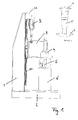
- the illustrated frame 20 has a base plate 2, on which a workpiece 6 to be welded can be arranged and which is rigidly connected to an upright column 1.
- a cantilever arm 12 At the top of the column 1, a cantilever arm 12 is mounted comparatively rigid, which in turn carries a drive 3 for generating the required welding force F.
- the welding force F of the drive 3 is transmitted via a slide 9, which is displaceably guided along a guide rail 10 on the column 1 in the vertical direction, to a working organ serving as a sonotrode 5, which is supported by the carriage 9 and the vibration of a fourth is excited to the carriage 9 to high-frequency oscillations.
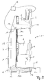
- FIG Fig. 2 is shown schematically.
- the column 1 has been bent to the left due to the application of the welding force F on the workpiece 6, which undesirably results in that the head of the sonotrode 5 is no longer in the desired manner over the entire surface on the surface of the workpiece 6, such as especially in the enlarged detail "A" of Fig. 2 can be recognized.
- such unparallelism between sonotrode 5 and workpiece 6 can undesirably be at the expense of the result of the work and, in particular, at the expense of the weld seam quality.
- Another frame is also from the document DE 83 16 643 U1 known.
- This frame has features of the upper handle of claim 1 and in particular has a trained in the manner of a gallows suspension device to which a suspension element a spindle box is suspended.
- a gallows suspension device to which a suspension element a spindle box is suspended.
- the suspension device is mounted only by means of a roller on the running surface of a beam-like support element.
- no lifting forces can be removed via the gallows-like suspension device, ie no forces that can arise as a result of a force applied by a tool.
- the invention is therefore based on the object to provide a frame for a welding machine, in which a bending of the frame, which is due to lifting forces, which are caused in response to forces applied to a workpiece, is minimized.
- the linear drive is therefore not supported by the column of the frame of the welding machine but by an additional support, which can be formed for example by a support member which is supported by the base plate, which will be discussed in more detail later.
- this support can be made relatively stiff, for example, by appropriate dimensioning of said support member, so that this deformed relatively little due to the welding force generated by the linear drive; Nevertheless, any deformations of the support or the support member can not be completely excluded, especially in the vertical direction, which is why it is provided according to the invention to avoid unwanted forced voltages in the linear drive as well as in this carrying carriage, that this carriage is guided displaceably along the guide rail extends in a vertical direction along the column.
- the carriage together with the linear drive can therefore yield guided in the vertical direction when the support bearing the carriage is slightly deflected in a vertical upward direction due to a welding force generated by the linear drive.
- the column is not deflected as a result of the welding force, which avoids possible non-parallelism between the sonotrode and the workpiece in the desired manner.
- the working member in the form of the sonotrode with the actuator of the linear actuator is aligned or is arranged in extension of the travel of the same. If it is mentioned here that the working member is aligned with the linear drive or its travel or other positions, this means that there is essentially no offset between the working member and the linear drive or its travel or the other positions. It will be like this good as no offset moments generated, so that the carriage is not tilted. Thus, the desired alignment between the working member and the workpiece can be substantially maintained even under load.
- the support for the carriage, which carries the linear drive can be formed in accordance with the above statements by a support member which is connected to the base plate;
- the support in question it would also be possible for the support in question to be formed, for example, by a cantilever beam, a bracket or the like, which is an integral part of the production line in which the welding frame is located.
- the base plate together with the pillar can stand on a table, whereas the support is formed by an on-site stationary structural member such as a wall projection or a support bracket or the like.
- the support can slidably support the carriage in the horizontal direction so as to be able to compensate for any differences in movement between the stationary structural member and the carriage.
- the carriage may be coupled via a horizontal slotted guide with the support, which is formed by a guided in a slot pin.
- the support is formed by a support member which carries both with the carriage, which carries the linear drive, as well as with the Base plate is preferably hingedly connected.
- the support member is thus an integral part of the frame according to the invention, so that the welding frame can basically be set up at any location and used.
- the support member may for example be formed by a relatively rigid rod or carrier, which connects the base plate with the carriage which carries the linear drive.
- the rod or support By virtue of the rod or support, the slide is thus to a certain extent coupled to the base plate, so that the slide can deform only as part of the elastic deformation of the rod or of the carrier as a result of a welding force generated by the linear drive.
- the support member is formed by at least one preferably substantially C-shaped bracket, which in the region of its two free Ends hinged to the carriage or the base plate is connected.
- the at least one essentially C-shaped bracket may preferably have a web section and a first and a second flange section, wherein the web section runs parallel to the column of the frame and the two flange sections protrude from the web section in a manner of a ridge.
- the first flange portion is hingedly connected at its free end to the carriage for the linear drive
- the second flange portion is hingedly connected at its free end to the base plate.
- the second flange portion is received by the base plate, for which purpose the base plate can form a receiving cavity into which the respective bracket extends with its second flange portion.
- the working space between the carriage and the base plate is thus in a sense partially surrounded by the at least one substantially C-shaped bracket, so that the working space is free from interference by the bracket.
- the frame has two substantially C-shaped bracket whose web sections flank the column of the frame on both sides. Each of the two brackets thus receives approximately the same load, whereby any deformations perpendicular to the ironing plane due to unbalanced load conditions is counteracted.
- the working member is aligned in the form of sonotrode with the actuator of the linear drive or in extension of the travel of the same is arranged.
- it may be provided to ensure only vertical movement components of the carriage and to minimize bending of the frame that the articulated joints of the support member with the carriage and the base plate are aligned with the travel of the linear drive.
- the linear drive and the working member and the connection points of the support member with the carriage and the base plate are substantially on a straight line, since this can be achieved that caused by the linear drive welding force largely implemented in a purely vertical component movement of the carriage becomes.
- the sonotrode is driven by a vibrating structure, which is also displaceably guided along the guide rail, for example via a second carriage, which in turn carries the sonotrode. It is thus only a single guide rail needed to realize the slidable storage of the two carriages along the column of the frame can.
- a deformation measuring device such as a strain gauge is provided on the support member, which is preferably in the region of weakening of the support member or one of the bracket.
- the deformation measuring device is set up to provide a deformation variable of the support member of a force control device representative of the force applied by the linear drive so that it can take into account the deformation variable or a force variable derived therefrom as a controlled variable in the context of force regulation for the linear drive.
- the support member will deform all the more with increasing welding force, so that the deformation of the support member for the applied welding force is representative.
- the weight of the two slides, the linear drive and the oscillatory structure including the sonotrode is removed via the support member in the unloaded state.
- different sonotrodes and Vibrating structures can be used, this leads to the fact that in the unloaded state, the support structure undergoes a different strong or large pre-deformation.
- the force control device is further adapted to calibrate the deformation amount provided by the deformation measuring device in dependence on a pre-deformation of the support member. The force control device is thus to a certain extent set up to carry out a tare function and thus a zero adjustment of the deformation measuring device.
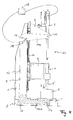
- the frame 20 for a welding machine serving as a base for the welding machine base plate 2, which is shown here in a partially broken-away view and serves to receive a workpiece 6. Furthermore, the frame 20 has an upright column 1, which is rigidly connected to the base plate 2. On the column 1, a guide rail 10 is mounted, which extends in the longitudinal direction of the column 1 in the vertical direction. The guide rail 10 is used here, on the one hand, the displaceable mounting of a first carriage 8 for a linear drive 3 in the region of the upper end of the support 1 and a second carriage 9 for a vibrating structure 4 for a sonotrode 5 in a work area between the first carriage 8 and the base plate. 2
- the first carriage 8 is displaceably guided along the guide rail 10 and carries a linear drive 3, which may, for example, be a spindle drive, a piston-cylinder unit or a linear motor and which serves to move onto the workpiece 6 via the working member serving sonotrode 5 to apply a welding force F.
- a linear drive 3 which may, for example, be a spindle drive, a piston-cylinder unit or a linear motor and which serves to move onto the workpiece 6 via the working member serving sonotrode 5 to apply a welding force F.
- the linear actuator 3 is not rigidly connected via a cantilever with the column 1; Rather, it is inventively provided that the linear drive 3 is mounted displaceably in the vertical direction on the column 1.
- the first carriage 8 is supported by a support, which in the embodiment shown here by two C-shaped bracket. 7 is formed, which flank the column 1 of the frame 20 on both sides.
- Each of the two substantially C-shaped bracket 7 in this case has a web portion 13 and a first and a second flange portion 14a, 14b, which protrude from the web portion 13 and are formed integrally therewith.
- the first flange portion 14a of the respective bracket 7 is hinged at its free end at a junction 15 with the first carriage 8, for example by means of a bolt connection.
- the second flange portion 14b is articulated at its free end at a junction 16 with the base plate 2, for example by means of a bolt connection, for which he hineinzreckt into a receiving cavity 11, which forms the base plate 2.
- the two brackets 7 are thus by the base plate 2 in vertical Direction supported by these are hinged to the base plate 2.
- the two brackets 7 thus the first carriage 8 and the base plate 2 are coupled together, with the result that the two brackets 7 counteract a force-induced displacement of the first carriage 8 by the linear drive 3, but this does not mean that the first carriage 8 no displacement experiences.
- the free ends of the two ironing flanges 14a, 14b are spread apart in the vertical direction parallel to the column 1, when a welding force F is transmitted through the linear drive 3 via the second carriage 9 and the vibrating structure 4 supported therefrom on the working member 5.
- the lifting reaction force which is caused in response to the NASAwn on the workpiece 6 welding force F, introduced via the bracket 7 as a tensile force in the base plate 2, which due to the articulated connection of the two flange portions 14a, 14b with the carriage 8 or the base plate 2 is possible.
- the two articulated connection points 15, 16 may thus be, for example, bolt connections or any other types of connection, provided that these forces can be transferred to the brackets 7 and from these to the base plate 2.
- the free end of the upper bracket flange 14a experiences exclusively a component of movement in the vertical direction, it is provided in the illustrated preferred embodiment that the working member 5 is aligned with the linear drive 3 and its travel and that the articulated connection points 15, 16 of the two Flanges 14a, 14b are aligned with the first carriage 8 and the base plate 2 with the travel of the linear drive 3.
- bracket 7 are supported by the first carriage 8 in the horizontal direction on the column 1, so that the bracket 7 are held in the desired position.
- the first carriage 8 thus forms a monovalent or displaceable support for the two brackets 7, which prevents the bracket 7 from tipping over the connection point 16 with the base plate, which for the bracket 7 in the static sense a bivalent or articulated Support forms.
- a deformation measuring device in the form of a strain gauge 17 is provided on at least one of the brackets 7 in the illustrated embodiment.
- the strain gauge 17 is arranged in the transition region between the upper bracket flange 14a and the hoop web 13 and thus in a region in which relatively large relative deformations take place.
- the bracket 7 is targeted in the mentioned transition region with a weakening 18th Mistake.
- the deformation variable detected by the deformation measuring device 17 is representative of the welding force F applied by the linear drive 3, wherein the relationship between deformation and welding force F can be stored in a look-up table.
- the deformation amount detected by the deformation measuring device 17 is now made available to a force control device 19 which is set up to take into account the deformation variable or a force variable derived therefrom as a controlled variable in the context of a force control for the linear drive 3.
- the force control device 19 thus compares the deformation quantity or a force variable derived therefrom with a setpoint value of the welding force F in order to determine a manipulated variable for regulating the linear drive 3 as a function of the difference between the setpoint value and the controlled variable.
- the support structure may have different strengths in the unloaded state or undergoes large pre-deformations. Since these pre-deformations are also detected by the deformation measuring device 17, it is therefore provided in the illustrated embodiment that the force control device 19 is further configured to calibrate the deformation amount provided by the deformation measuring device 17 as a function of a pre-deformation of the brackets 7. The force control device 19 is thus to a certain extent set up to carry out a tare function and thus a zero adjustment of the deformation measuring device.
Landscapes
- Engineering & Computer Science (AREA)
- Mechanical Engineering (AREA)
- Physics & Mathematics (AREA)
- Optics & Photonics (AREA)
- Lining Or Joining Of Plastics Or The Like (AREA)
- Butt Welding And Welding Of Specific Article (AREA)
- Resistance Welding (AREA)
- Automatic Assembly (AREA)
Applications Claiming Priority (1)
| Application Number | Priority Date | Filing Date | Title |
|---|---|---|---|
| DE102014101627.0A DE102014101627A1 (de) | 2014-02-10 | 2014-02-10 | Gestell für eine Maschine |
Publications (2)
| Publication Number | Publication Date |
|---|---|
| EP2905108A1 true EP2905108A1 (fr) | 2015-08-12 |
| EP2905108B1 EP2905108B1 (fr) | 2016-09-14 |
Family
ID=52391819
Family Applications (1)
| Application Number | Title | Priority Date | Filing Date |
|---|---|---|---|
| EP15151875.0A Active EP2905108B1 (fr) | 2014-02-10 | 2015-01-21 | Châssis d'une machine |
Country Status (7)
| Country | Link |
|---|---|
| US (1) | US9296071B2 (fr) |
| EP (1) | EP2905108B1 (fr) |
| DE (1) | DE102014101627A1 (fr) |
| ES (1) | ES2602057T3 (fr) |
| HU (1) | HUE030469T2 (fr) |
| PL (1) | PL2905108T3 (fr) |
| PT (1) | PT2905108T (fr) |
Cited By (6)
| Publication number | Priority date | Publication date | Assignee | Title |
|---|---|---|---|---|
| DE102016102164A1 (de) * | 2016-02-08 | 2017-08-10 | Ms Ultraschall Technologie Gmbh | Ultraschall-Bearbeitungsmaschine |
| EP3178599A3 (fr) * | 2015-12-08 | 2017-08-30 | MS Ultraschall Technologie GmbH | Machine sur colonne |
| CN110142554A (zh) * | 2019-06-20 | 2019-08-20 | 诺力智能装备股份有限公司 | 一种适用于工业车辆快速脱模焊接工装 |
| WO2020035326A1 (fr) | 2018-08-13 | 2020-02-20 | Branson Ultraschall Niederlassung Der Emerson Technologies Gmbh & Co. Ohg | Dispositif de soudage et support pour celui-ci |
| CN113579400A (zh) * | 2021-08-25 | 2021-11-02 | 深圳市佳润芯电子科技有限公司 | 一种集成电路板电子元件自动焊接设备 |
| CN116833609A (zh) * | 2023-08-24 | 2023-10-03 | 江苏丰恩金属制品有限公司 | 压力容器的焊接系统 |
Families Citing this family (6)
| Publication number | Priority date | Publication date | Assignee | Title |
|---|---|---|---|---|
| DE102016112297A1 (de) * | 2016-07-05 | 2018-01-11 | Ejot Gmbh & Co. Kg | Vorrichtung zur Verbindung von zwei Bauteillagen |
| DE102017010965A1 (de) * | 2017-11-27 | 2019-05-29 | Grenzebach Maschinenbau Gmbh | Vorrichtung und Verfahren zum nahezu verzögerungsfreien Ändern der Schweißrichtung der Schweißschulter einer Anlage zum Rührreibschweißen wenn die geometrische Anordnung der zu verschweißenden Fügepartner oder Materialunebenheiten dies erfordern |
| CN108422136A (zh) * | 2018-05-11 | 2018-08-21 | 深圳市诺峰光电设备有限公司 | 一种全自动焊接机 |
| CN109228366A (zh) * | 2018-09-14 | 2019-01-18 | 必能信超声(上海)有限公司 | 激光焊接机 |
| DE102019107539A1 (de) * | 2019-03-25 | 2020-10-01 | Weber Ultrasonics AG | Gestell für eine Bearbeitungsmaschine und Verfahren zum Bearbeiten eines Werkstücks mit derselben |
| CN117961258A (zh) * | 2024-03-28 | 2024-05-03 | 杭州海颂科技有限公司 | 一种超声波焊接机及焊接生产线 |
Citations (5)
| Publication number | Priority date | Publication date | Assignee | Title |
|---|---|---|---|---|
| DE1938071A1 (de) * | 1968-07-30 | 1970-02-26 | Heller Geb Gmbh Maschf | Werkzeugmaschine |
| US3684395A (en) * | 1969-12-09 | 1972-08-15 | Mitsubishi Heavy Ind Ltd | Headstock balancing construction for machine tools |
| DD99938A1 (fr) * | 1972-11-13 | 1973-09-05 | ||
| DE8316643U1 (de) | 1982-12-10 | 1983-10-06 | Mdc Max Daetwyler Bleienbach Ag, 3368 Bleienbach | Vorrichtung zum Entlasten der Führung für zumindest in im wesentlichen vertikaler Richtung bewegbare Bauteile, insbesondere von Bearbeitungsmaschinen, wie beispielsweise Werkzeugmaschinen |
| JPS6080508A (ja) * | 1983-10-07 | 1985-05-08 | Mitsubishi Heavy Ind Ltd | 工作機械のバランス装置 |
Family Cites Families (43)
| Publication number | Priority date | Publication date | Assignee | Title |
|---|---|---|---|---|
| US3905862A (en) * | 1973-10-17 | 1975-09-16 | Hitachi Ltd | Caulking apparatus |
| US4224091A (en) * | 1977-12-01 | 1980-09-23 | Branson Ultrasonics Corp. | Method of producing corners in channel material using ultrasonic energy |
| US4584037A (en) * | 1982-09-07 | 1986-04-22 | Cosden Technology, Inc. | Inertial spin welding of thermoplastic and thermoplastic coated container parts |
| US4527727A (en) * | 1983-04-12 | 1985-07-09 | Fairchild Industries, Inc. | Stabilized ultrasonic welding apparatus |
| US4545519A (en) * | 1983-04-12 | 1985-10-08 | Fairchild Industries, Inc. | Method and apparatus for preventing tip sticking during welding operation |
| US5772103A (en) * | 1996-09-25 | 1998-06-30 | Hofius, Sr.; David V. | Method and apparatus for friction torque welding |
| US6170731B1 (en) * | 1996-09-25 | 2001-01-09 | David V. Hofius, Sr. | Method and apparatus for friction torque welding |
| US5833127A (en) * | 1996-12-12 | 1998-11-10 | Powell Mcgee Associates, Inc. | Method and apparatus for precision spin-welding |
| EP1097869B1 (fr) * | 1998-03-23 | 2005-08-17 | Shikoku Kakoki Co., Ltd. | Scelleuse a ultrason |
| DE19813121C1 (de) * | 1998-03-25 | 1999-10-28 | Kuesters Eduard Maschf | Vorrichtung zum Bearbeiten einer Materialbahn mit Ultraschall |
| US6620291B1 (en) * | 1998-12-16 | 2003-09-16 | The Goodyear Tire & Rubber Company | Apparatus for tying rolls of fabric |
| JP3290632B2 (ja) * | 1999-01-06 | 2002-06-10 | 株式会社アルテクス | 超音波振動接合装置 |
| JP3447982B2 (ja) * | 1999-06-16 | 2003-09-16 | 株式会社アルテクス | 超音波振動接合装置 |
| DE29917831U1 (de) * | 1999-10-09 | 2001-02-22 | Eduard Küsters Maschinenfabrik GmbH & Co. KG, 47805 Krefeld | Vorrichtung zum Bearbeiten einer Materialbahn mit Ultraschall |
| JP3599706B2 (ja) * | 1999-11-30 | 2004-12-08 | 東レエンジニアリング株式会社 | チップボンディング装置 |
| US6302315B1 (en) * | 2000-05-01 | 2001-10-16 | General Tool Company | Friction stir welding machine and method |
| US6296726B1 (en) * | 2000-06-13 | 2001-10-02 | Silgan Containers Corporation | Method and apparatus for spin welding container closures |
| JP2002066763A (ja) * | 2000-09-01 | 2002-03-05 | Honda Motor Co Ltd | 摩擦撹拌接合装置 |
| US6517651B2 (en) * | 2000-12-21 | 2003-02-11 | Tefron Ltd. | Apparatus and method for joining fabrics without sewing |
| US6612479B2 (en) * | 2001-10-10 | 2003-09-02 | Ford Global Technologies, Llc | Apparatus and method for joining layers of materials |
| US6810936B2 (en) * | 2001-10-30 | 2004-11-02 | International Product Technology, Inc. | Method and apparatus for sealing cover tape to carrier tape |
| JP3538419B2 (ja) * | 2002-08-20 | 2004-06-14 | 川崎重工業株式会社 | 摩擦撹拌接合装置 |
| JP2004136331A (ja) * | 2002-10-18 | 2004-05-13 | Hitachi Ltd | 摩擦攪拌接合装置及び接合方法 |
| JP2004141898A (ja) * | 2002-10-23 | 2004-05-20 | Hitachi Ltd | 摩擦攪拌接合方法および装置 |
| US9914263B2 (en) * | 2006-05-08 | 2018-03-13 | Dukane Ias, Llc | Ultrasonic press with automatic speed changes in advancing movement of welding stack |
| US8052816B2 (en) * | 2006-05-08 | 2011-11-08 | Dukane Corporation | Ultrasonic press using servo motor with delayed motion |
| WO2008018935A2 (fr) * | 2006-05-08 | 2008-02-14 | Dukane Corporation | Presse ultrasonique utilisant un servomoteur comprenant un actionneur linéaire intégré |
| JP4138850B1 (ja) * | 2007-07-24 | 2008-08-27 | 伊藤 仁彦 | 超音波振動接合装置 |
| JP5081609B2 (ja) * | 2007-12-21 | 2012-11-28 | 川崎重工業株式会社 | 摩擦撹拌スポット接合装置 |
| WO2009098836A1 (fr) * | 2008-02-08 | 2009-08-13 | Fuji Electric Fa Components & Systems Co., Ltd. | Procédé de fabrication de contact électrique et équipement de fabrication de contact électrique |
| JP4311582B1 (ja) * | 2008-04-07 | 2009-08-12 | 株式会社アドウェルズ | 共振器の支持装置 |
| JP4336732B1 (ja) * | 2008-04-11 | 2009-09-30 | Tdk株式会社 | 超音波実装装置 |
| JP4564548B2 (ja) * | 2008-04-28 | 2010-10-20 | 株式会社アルテクス | 超音波振動接合用共振器とそれを支持する支持装置 |
| US8052034B2 (en) * | 2008-05-30 | 2011-11-08 | Vanderbilt University | Lateral position detection and control for friction stir systems |
| DE102008039872A1 (de) * | 2008-08-27 | 2010-03-04 | Robert Bosch Gmbh | Widerstandsschweißanordnung |
| DE102008063277A1 (de) * | 2008-12-29 | 2010-07-08 | Bwg Bergwerk- Und Walzwerk-Maschinenbau Gmbh | Verfahren und Vorrichtung zum Verbinden von Metallbändern |
| DE102009038697A1 (de) * | 2009-08-24 | 2011-03-17 | Ejot Gmbh & Co. Kg | Vorrichtung zum Verbinden von mindestens zwei Platten |
| JP5613898B2 (ja) * | 2010-03-24 | 2014-10-29 | 公立大学法人大阪府立大学 | 摩擦加工装置及び摩擦加工方法 |
| US8070039B1 (en) * | 2010-08-25 | 2011-12-06 | APCI, Inc. | Linear friction welder |
| JP5631162B2 (ja) * | 2010-11-16 | 2014-11-26 | カルソニックカンセイ株式会社 | 摩擦攪拌接合方法 |
| JP5374528B2 (ja) * | 2011-02-18 | 2013-12-25 | 三菱重工業株式会社 | 摩擦攪拌接合装置及び摩擦攪拌接合方法 |
| US9233501B2 (en) * | 2011-12-05 | 2016-01-12 | Apci, Llc | Apparatus for linear friction welding |
| TWI576292B (zh) * | 2013-03-12 | 2017-04-01 | Chan Li Machinery Co Ltd | Packaging bag heat sealing device |
-
2014
- 2014-02-10 DE DE102014101627.0A patent/DE102014101627A1/de not_active Withdrawn
-
2015
- 2015-01-21 EP EP15151875.0A patent/EP2905108B1/fr active Active
- 2015-01-21 ES ES15151875.0T patent/ES2602057T3/es active Active
- 2015-01-21 PL PL15151875T patent/PL2905108T3/pl unknown
- 2015-01-21 HU HUE15151875A patent/HUE030469T2/en unknown
- 2015-01-21 PT PT151518750T patent/PT2905108T/pt unknown
- 2015-02-04 US US14/613,660 patent/US9296071B2/en active Active
Patent Citations (5)
| Publication number | Priority date | Publication date | Assignee | Title |
|---|---|---|---|---|
| DE1938071A1 (de) * | 1968-07-30 | 1970-02-26 | Heller Geb Gmbh Maschf | Werkzeugmaschine |
| US3684395A (en) * | 1969-12-09 | 1972-08-15 | Mitsubishi Heavy Ind Ltd | Headstock balancing construction for machine tools |
| DD99938A1 (fr) * | 1972-11-13 | 1973-09-05 | ||
| DE8316643U1 (de) | 1982-12-10 | 1983-10-06 | Mdc Max Daetwyler Bleienbach Ag, 3368 Bleienbach | Vorrichtung zum Entlasten der Führung für zumindest in im wesentlichen vertikaler Richtung bewegbare Bauteile, insbesondere von Bearbeitungsmaschinen, wie beispielsweise Werkzeugmaschinen |
| JPS6080508A (ja) * | 1983-10-07 | 1985-05-08 | Mitsubishi Heavy Ind Ltd | 工作機械のバランス装置 |
Cited By (8)
| Publication number | Priority date | Publication date | Assignee | Title |
|---|---|---|---|---|
| EP3178599A3 (fr) * | 2015-12-08 | 2017-08-30 | MS Ultraschall Technologie GmbH | Machine sur colonne |
| DE102016102164A1 (de) * | 2016-02-08 | 2017-08-10 | Ms Ultraschall Technologie Gmbh | Ultraschall-Bearbeitungsmaschine |
| US9919471B2 (en) | 2016-02-08 | 2018-03-20 | Ms Ultraschall Technologie Gmbh | Ultrasonic machine tool |
| WO2020035326A1 (fr) | 2018-08-13 | 2020-02-20 | Branson Ultraschall Niederlassung Der Emerson Technologies Gmbh & Co. Ohg | Dispositif de soudage et support pour celui-ci |
| CN110142554A (zh) * | 2019-06-20 | 2019-08-20 | 诺力智能装备股份有限公司 | 一种适用于工业车辆快速脱模焊接工装 |
| CN113579400A (zh) * | 2021-08-25 | 2021-11-02 | 深圳市佳润芯电子科技有限公司 | 一种集成电路板电子元件自动焊接设备 |
| CN116833609A (zh) * | 2023-08-24 | 2023-10-03 | 江苏丰恩金属制品有限公司 | 压力容器的焊接系统 |
| CN116833609B (zh) * | 2023-08-24 | 2024-04-02 | 江苏丰恩金属制品有限公司 | 压力容器的焊接系统 |
Also Published As
| Publication number | Publication date |
|---|---|
| US20150224605A1 (en) | 2015-08-13 |
| EP2905108B1 (fr) | 2016-09-14 |
| DE102014101627A1 (de) | 2015-08-13 |
| ES2602057T3 (es) | 2017-02-17 |
| US9296071B2 (en) | 2016-03-29 |
| PT2905108T (pt) | 2016-11-10 |
| PL2905108T3 (pl) | 2017-03-31 |
| HUE030469T2 (en) | 2017-05-29 |
Similar Documents
| Publication | Publication Date | Title |
|---|---|---|
| EP2905108B1 (fr) | Châssis d'une machine | |
| AT515153B1 (de) | Biegemaschine | |
| DE102015122314B3 (de) | Linearreibschweißmaschine | |
| EP3160726B1 (fr) | Presse à châssis en c, améliorée | |
| DE2504808A1 (de) | Wiegeblechschere | |
| EP3112083B1 (fr) | Système de portique d'une machine-outil et machine-outil avec un tel système de portique | |
| EP3552729B1 (fr) | Dispositif d'installation de rivets auto-poinçonneurs | |
| DE3424683A1 (de) | Fahrbare gleisstopfmaschine, insbesondere gleis-stopf-, nivellier- und richtmaschine | |
| EP3820679B1 (fr) | Dispositif de soudage et support pour celui-ci | |
| DE19706622A1 (de) | Richtmaschine zum Richten von langgestreckten Stahlträgern und Verfahren zum Betrieb der Richtmaschine | |
| EP4353467B1 (fr) | Dispositif de pliage pour plier une ébauche de carton | |
| DE102012012139B4 (de) | Vorrichtung und Verfahren zum Biegen von Rohrleitungen für Pipelines | |
| EP2829452A1 (fr) | Module de porte oscillo-battante/module de porte coulissante pour un véhicule sur rail doté d'au moins deux chariots/véhicules de guidage par vantail de porte | |
| DE102019107539A1 (de) | Gestell für eine Bearbeitungsmaschine und Verfahren zum Bearbeiten eines Werkstücks mit derselben | |
| EP1103348B1 (fr) | Dispositif de soudage de cadres | |
| DE102012102526B4 (de) | C-Gestell-Presse | |
| DE102007039146A1 (de) | Schlittenführung einer Werkzeugmaschine | |
| EP2907720B1 (fr) | Module de porte oscillo-battante/module de porte coulissante pour un véhicule sur rail doté d'une structure portante élastique | |
| DE4402061C1 (de) | Feststehendes Portal für Präzisions-Koordinatenmeßgeräte | |
| EP3178599A2 (fr) | Machine sur colonne | |
| EP3061538B1 (fr) | Presse plieuse | |
| EP1852230B1 (fr) | Presse à carcasses | |
| DE102005039945B4 (de) | Scherenhubtisch | |
| EP3492218A1 (fr) | Dispositif porte-pièces | |
| EP2052112A1 (fr) | Procédé pour bourrer et stabiliser une voie |
Legal Events
| Date | Code | Title | Description |
|---|---|---|---|
| PUAI | Public reference made under article 153(3) epc to a published international application that has entered the european phase |
Free format text: ORIGINAL CODE: 0009012 |
|
| AK | Designated contracting states |
Kind code of ref document: A1 Designated state(s): AL AT BE BG CH CY CZ DE DK EE ES FI FR GB GR HR HU IE IS IT LI LT LU LV MC MK MT NL NO PL PT RO RS SE SI SK SM TR |
|
| AX | Request for extension of the european patent |
Extension state: BA ME |
|
| 17P | Request for examination filed |
Effective date: 20150921 |
|
| RBV | Designated contracting states (corrected) |
Designated state(s): AL AT BE BG CH CY CZ DE DK EE ES FI FR GB GR HR HU IE IS IT LI LT LU LV MC MK MT NL NO PL PT RO RS SE SI SK SM TR |
|
| GRAP | Despatch of communication of intention to grant a patent |
Free format text: ORIGINAL CODE: EPIDOSNIGR1 |
|
| RIC1 | Information provided on ipc code assigned before grant |
Ipc: B23Q 11/00 20060101AFI20160216BHEP Ipc: B23K 37/00 20060101ALI20160216BHEP Ipc: B23K 20/10 20060101ALI20160216BHEP |
|
| INTG | Intention to grant announced |
Effective date: 20160303 |
|
| GRAS | Grant fee paid |
Free format text: ORIGINAL CODE: EPIDOSNIGR3 |
|
| GRAA | (expected) grant |
Free format text: ORIGINAL CODE: 0009210 |
|
| RAP1 | Party data changed (applicant data changed or rights of an application transferred) |
Owner name: MS ULTRASCHALL TECHNOLOGIE GMBH |
|
| AK | Designated contracting states |
Kind code of ref document: B1 Designated state(s): AL AT BE BG CH CY CZ DE DK EE ES FI FR GB GR HR HU IE IS IT LI LT LU LV MC MK MT NL NO PL PT RO RS SE SI SK SM TR |
|
| REG | Reference to a national code |
Ref country code: GB Ref legal event code: FG4D Free format text: NOT ENGLISH |
|
| REG | Reference to a national code |
Ref country code: CH Ref legal event code: EP Ref country code: CH Ref legal event code: NV Representative=s name: INTELLECTUAL PROPERTY SERVICES GMBH, CH |
|
| REG | Reference to a national code |
Ref country code: IE Ref legal event code: FG4D Free format text: LANGUAGE OF EP DOCUMENT: GERMAN |
|
| REG | Reference to a national code |
Ref country code: AT Ref legal event code: REF Ref document number: 828398 Country of ref document: AT Kind code of ref document: T Effective date: 20161015 |
|
| REG | Reference to a national code |
Ref country code: DE Ref legal event code: R096 Ref document number: 502015000149 Country of ref document: DE |
|
| REG | Reference to a national code |
Ref country code: PT Ref legal event code: SC4A Ref document number: 2905108 Country of ref document: PT Date of ref document: 20161110 Kind code of ref document: T Free format text: AVAILABILITY OF NATIONAL TRANSLATION Effective date: 20161103 |
|
| REG | Reference to a national code |
Ref country code: NL Ref legal event code: FP |
|
| REG | Reference to a national code |
Ref country code: SE Ref legal event code: TRGR |
|
| REG | Reference to a national code |
Ref country code: LT Ref legal event code: MG4D |
|
| REG | Reference to a national code |
Ref country code: FR Ref legal event code: PLFP Year of fee payment: 3 |
|
| PG25 | Lapsed in a contracting state [announced via postgrant information from national office to epo] |
Ref country code: HR Free format text: LAPSE BECAUSE OF FAILURE TO SUBMIT A TRANSLATION OF THE DESCRIPTION OR TO PAY THE FEE WITHIN THE PRESCRIBED TIME-LIMIT Effective date: 20160914 Ref country code: RS Free format text: LAPSE BECAUSE OF FAILURE TO SUBMIT A TRANSLATION OF THE DESCRIPTION OR TO PAY THE FEE WITHIN THE PRESCRIBED TIME-LIMIT Effective date: 20160914 Ref country code: NO Free format text: LAPSE BECAUSE OF FAILURE TO SUBMIT A TRANSLATION OF THE DESCRIPTION OR TO PAY THE FEE WITHIN THE PRESCRIBED TIME-LIMIT Effective date: 20161214 Ref country code: FI Free format text: LAPSE BECAUSE OF FAILURE TO SUBMIT A TRANSLATION OF THE DESCRIPTION OR TO PAY THE FEE WITHIN THE PRESCRIBED TIME-LIMIT Effective date: 20160914 Ref country code: LT Free format text: LAPSE BECAUSE OF FAILURE TO SUBMIT A TRANSLATION OF THE DESCRIPTION OR TO PAY THE FEE WITHIN THE PRESCRIBED TIME-LIMIT Effective date: 20160914 |
|
| REG | Reference to a national code |
Ref country code: ES Ref legal event code: FG2A Ref document number: 2602057 Country of ref document: ES Kind code of ref document: T3 Effective date: 20170217 |
|
| PG25 | Lapsed in a contracting state [announced via postgrant information from national office to epo] |
Ref country code: LV Free format text: LAPSE BECAUSE OF FAILURE TO SUBMIT A TRANSLATION OF THE DESCRIPTION OR TO PAY THE FEE WITHIN THE PRESCRIBED TIME-LIMIT Effective date: 20160914 Ref country code: GR Free format text: LAPSE BECAUSE OF FAILURE TO SUBMIT A TRANSLATION OF THE DESCRIPTION OR TO PAY THE FEE WITHIN THE PRESCRIBED TIME-LIMIT Effective date: 20161215 |
|
| PG25 | Lapsed in a contracting state [announced via postgrant information from national office to epo] |
Ref country code: EE Free format text: LAPSE BECAUSE OF FAILURE TO SUBMIT A TRANSLATION OF THE DESCRIPTION OR TO PAY THE FEE WITHIN THE PRESCRIBED TIME-LIMIT Effective date: 20160914 Ref country code: RO Free format text: LAPSE BECAUSE OF FAILURE TO SUBMIT A TRANSLATION OF THE DESCRIPTION OR TO PAY THE FEE WITHIN THE PRESCRIBED TIME-LIMIT Effective date: 20160914 |
|
| REG | Reference to a national code |
Ref country code: HU Ref legal event code: AG4A Ref document number: E030469 Country of ref document: HU |
|
| PG25 | Lapsed in a contracting state [announced via postgrant information from national office to epo] |
Ref country code: SM Free format text: LAPSE BECAUSE OF FAILURE TO SUBMIT A TRANSLATION OF THE DESCRIPTION OR TO PAY THE FEE WITHIN THE PRESCRIBED TIME-LIMIT Effective date: 20160914 Ref country code: BG Free format text: LAPSE BECAUSE OF FAILURE TO SUBMIT A TRANSLATION OF THE DESCRIPTION OR TO PAY THE FEE WITHIN THE PRESCRIBED TIME-LIMIT Effective date: 20161214 Ref country code: IS Free format text: LAPSE BECAUSE OF FAILURE TO SUBMIT A TRANSLATION OF THE DESCRIPTION OR TO PAY THE FEE WITHIN THE PRESCRIBED TIME-LIMIT Effective date: 20170114 |
|
| REG | Reference to a national code |
Ref country code: SK Ref legal event code: T3 Ref document number: E 22837 Country of ref document: SK |
|
| REG | Reference to a national code |
Ref country code: DE Ref legal event code: R097 Ref document number: 502015000149 Country of ref document: DE |
|
| PLBE | No opposition filed within time limit |
Free format text: ORIGINAL CODE: 0009261 |
|
| STAA | Information on the status of an ep patent application or granted ep patent |
Free format text: STATUS: NO OPPOSITION FILED WITHIN TIME LIMIT |
|
| PG25 | Lapsed in a contracting state [announced via postgrant information from national office to epo] |
Ref country code: DK Free format text: LAPSE BECAUSE OF FAILURE TO SUBMIT A TRANSLATION OF THE DESCRIPTION OR TO PAY THE FEE WITHIN THE PRESCRIBED TIME-LIMIT Effective date: 20160914 |
|
| 26N | No opposition filed |
Effective date: 20170615 |
|
| PG25 | Lapsed in a contracting state [announced via postgrant information from national office to epo] |
Ref country code: MC Free format text: LAPSE BECAUSE OF FAILURE TO SUBMIT A TRANSLATION OF THE DESCRIPTION OR TO PAY THE FEE WITHIN THE PRESCRIBED TIME-LIMIT Effective date: 20160914 |
|
| REG | Reference to a national code |
Ref country code: IE Ref legal event code: MM4A |
|
| PG25 | Lapsed in a contracting state [announced via postgrant information from national office to epo] |
Ref country code: SI Free format text: LAPSE BECAUSE OF FAILURE TO SUBMIT A TRANSLATION OF THE DESCRIPTION OR TO PAY THE FEE WITHIN THE PRESCRIBED TIME-LIMIT Effective date: 20160914 |
|
| REG | Reference to a national code |
Ref country code: FR Ref legal event code: PLFP Year of fee payment: 4 |
|
| PG25 | Lapsed in a contracting state [announced via postgrant information from national office to epo] |
Ref country code: IE Free format text: LAPSE BECAUSE OF NON-PAYMENT OF DUE FEES Effective date: 20170121 |
|
| PG25 | Lapsed in a contracting state [announced via postgrant information from national office to epo] |
Ref country code: MT Free format text: LAPSE BECAUSE OF FAILURE TO SUBMIT A TRANSLATION OF THE DESCRIPTION OR TO PAY THE FEE WITHIN THE PRESCRIBED TIME-LIMIT Effective date: 20160914 |
|
| PG25 | Lapsed in a contracting state [announced via postgrant information from national office to epo] |
Ref country code: AL Free format text: LAPSE BECAUSE OF FAILURE TO SUBMIT A TRANSLATION OF THE DESCRIPTION OR TO PAY THE FEE WITHIN THE PRESCRIBED TIME-LIMIT Effective date: 20160914 |
|
| PG25 | Lapsed in a contracting state [announced via postgrant information from national office to epo] |
Ref country code: CY Free format text: LAPSE BECAUSE OF FAILURE TO SUBMIT A TRANSLATION OF THE DESCRIPTION OR TO PAY THE FEE WITHIN THE PRESCRIBED TIME-LIMIT Effective date: 20160914 |
|
| PG25 | Lapsed in a contracting state [announced via postgrant information from national office to epo] |
Ref country code: MK Free format text: LAPSE BECAUSE OF FAILURE TO SUBMIT A TRANSLATION OF THE DESCRIPTION OR TO PAY THE FEE WITHIN THE PRESCRIBED TIME-LIMIT Effective date: 20160914 |
|
| REG | Reference to a national code |
Ref country code: DE Ref legal event code: R082 Ref document number: 502015000149 Country of ref document: DE Representative=s name: QIP PATENTANWAELTE, DR. KUEHN & PARTNER MBB, DE Ref country code: DE Ref legal event code: R082 Ref document number: 502015000149 Country of ref document: DE Representative=s name: QIP PATENT & RECHT, DR. KUEHN & PARTNER MBB, DE |
|
| REG | Reference to a national code |
Ref country code: CH Ref legal event code: U11 Free format text: ST27 STATUS EVENT CODE: U-0-0-U10-U11 (AS PROVIDED BY THE NATIONAL OFFICE) Effective date: 20260201 |
|
| PGFP | Annual fee paid to national office [announced via postgrant information from national office to epo] |
Ref country code: LU Payment date: 20260122 Year of fee payment: 12 Ref country code: NL Payment date: 20260122 Year of fee payment: 12 |
|
| PGFP | Annual fee paid to national office [announced via postgrant information from national office to epo] |
Ref country code: HU Payment date: 20260115 Year of fee payment: 12 |
|
| PGFP | Annual fee paid to national office [announced via postgrant information from national office to epo] |
Ref country code: SE Payment date: 20260126 Year of fee payment: 12 |
|
| PGFP | Annual fee paid to national office [announced via postgrant information from national office to epo] |
Ref country code: GB Payment date: 20260126 Year of fee payment: 12 |
|
| PGFP | Annual fee paid to national office [announced via postgrant information from national office to epo] |
Ref country code: ES Payment date: 20260210 Year of fee payment: 12 |
|
| PGFP | Annual fee paid to national office [announced via postgrant information from national office to epo] |
Ref country code: DE Payment date: 20260127 Year of fee payment: 12 |
|
| PGFP | Annual fee paid to national office [announced via postgrant information from national office to epo] |
Ref country code: AT Payment date: 20260119 Year of fee payment: 12 |
|
| PGFP | Annual fee paid to national office [announced via postgrant information from national office to epo] |
Ref country code: IT Payment date: 20260123 Year of fee payment: 12 Ref country code: BE Payment date: 20260123 Year of fee payment: 12 |
|
| PGFP | Annual fee paid to national office [announced via postgrant information from national office to epo] |
Ref country code: FR Payment date: 20260126 Year of fee payment: 12 |
|
| PGFP | Annual fee paid to national office [announced via postgrant information from national office to epo] |
Ref country code: TR Payment date: 20260109 Year of fee payment: 12 |
|
| PGFP | Annual fee paid to national office [announced via postgrant information from national office to epo] |
Ref country code: PT Payment date: 20260107 Year of fee payment: 12 Ref country code: CH Payment date: 20260201 Year of fee payment: 12 Ref country code: CZ Payment date: 20260113 Year of fee payment: 12 |
|
| PGFP | Annual fee paid to national office [announced via postgrant information from national office to epo] |
Ref country code: PL Payment date: 20260109 Year of fee payment: 12 |
|
| PGFP | Annual fee paid to national office [announced via postgrant information from national office to epo] |
Ref country code: SK Payment date: 20260108 Year of fee payment: 12 |