EP2934809B1 - Verfahren zum verschweissen von schienenenden und form dafür - Google Patents
Verfahren zum verschweissen von schienenenden und form dafür Download PDFInfo
- Publication number
- EP2934809B1 EP2934809B1 EP13818449.4A EP13818449A EP2934809B1 EP 2934809 B1 EP2934809 B1 EP 2934809B1 EP 13818449 A EP13818449 A EP 13818449A EP 2934809 B1 EP2934809 B1 EP 2934809B1
- Authority
- EP
- European Patent Office
- Prior art keywords
- welding
- rail
- portions
- weld
- volume
- Prior art date
- Legal status (The legal status is an assumption and is not a legal conclusion. Google has not performed a legal analysis and makes no representation as to the accuracy of the status listed.)
- Active
Links
Images


Classifications
-
- E—FIXED CONSTRUCTIONS
- E01—CONSTRUCTION OF ROADS, RAILWAYS, OR BRIDGES
- E01B—PERMANENT WAY; PERMANENT-WAY TOOLS; MACHINES FOR MAKING RAILWAYS OF ALL KINDS
- E01B11/00—Rail joints
- E01B11/44—Non-dismountable rail joints; Welded joints
-
- B—PERFORMING OPERATIONS; TRANSPORTING
- B23—MACHINE TOOLS; METAL-WORKING NOT OTHERWISE PROVIDED FOR
- B23K—SOLDERING OR UNSOLDERING; WELDING; CLADDING OR PLATING BY SOLDERING OR WELDING; CUTTING BY APPLYING HEAT LOCALLY, e.g. FLAME CUTTING; WORKING BY LASER BEAM
- B23K23/00—Alumino-thermic welding
-
- B—PERFORMING OPERATIONS; TRANSPORTING
- B22—CASTING; POWDER METALLURGY
- B22D—CASTING OF METALS; CASTING OF OTHER SUBSTANCES BY THE SAME PROCESSES OR DEVICES
- B22D19/00—Casting in, on, or around objects which form part of the product
- B22D19/04—Casting in, on, or around objects which form part of the product for joining parts
-
- B—PERFORMING OPERATIONS; TRANSPORTING
- B23—MACHINE TOOLS; METAL-WORKING NOT OTHERWISE PROVIDED FOR
- B23K—SOLDERING OR UNSOLDERING; WELDING; CLADDING OR PLATING BY SOLDERING OR WELDING; CUTTING BY APPLYING HEAT LOCALLY, e.g. FLAME CUTTING; WORKING BY LASER BEAM
- B23K20/00—Non-electric welding by applying impact or other pressure, with or without the application of heat, e.g. cladding or plating
- B23K20/002—Non-electric welding by applying impact or other pressure, with or without the application of heat, e.g. cladding or plating specially adapted for particular articles or work
-
- B—PERFORMING OPERATIONS; TRANSPORTING
- B23—MACHINE TOOLS; METAL-WORKING NOT OTHERWISE PROVIDED FOR
- B23K—SOLDERING OR UNSOLDERING; WELDING; CLADDING OR PLATING BY SOLDERING OR WELDING; CUTTING BY APPLYING HEAT LOCALLY, e.g. FLAME CUTTING; WORKING BY LASER BEAM
- B23K31/00—Processes relevant to this subclass, specially adapted for particular articles or purposes, but not covered by any single one of main groups B23K1/00 - B23K28/00
- B23K31/02—Processes relevant to this subclass, specially adapted for particular articles or purposes, but not covered by any single one of main groups B23K1/00 - B23K28/00 relating to soldering or welding
-
- E—FIXED CONSTRUCTIONS
- E01—CONSTRUCTION OF ROADS, RAILWAYS, OR BRIDGES
- E01B—PERMANENT WAY; PERMANENT-WAY TOOLS; MACHINES FOR MAKING RAILWAYS OF ALL KINDS
- E01B11/00—Rail joints
- E01B11/44—Non-dismountable rail joints; Welded joints
- E01B11/46—General methods for making gapless tracks
-
- E—FIXED CONSTRUCTIONS
- E01—CONSTRUCTION OF ROADS, RAILWAYS, OR BRIDGES
- E01B—PERMANENT WAY; PERMANENT-WAY TOOLS; MACHINES FOR MAKING RAILWAYS OF ALL KINDS
- E01B11/00—Rail joints
- E01B11/44—Non-dismountable rail joints; Welded joints
- E01B11/52—Joints made by alumino-thermal welding
-
- E—FIXED CONSTRUCTIONS
- E01—CONSTRUCTION OF ROADS, RAILWAYS, OR BRIDGES
- E01B—PERMANENT WAY; PERMANENT-WAY TOOLS; MACHINES FOR MAKING RAILWAYS OF ALL KINDS
- E01B26/00—Tracks or track components not covered by any one of the preceding groups
-
- E—FIXED CONSTRUCTIONS
- E01—CONSTRUCTION OF ROADS, RAILWAYS, OR BRIDGES
- E01B—PERMANENT WAY; PERMANENT-WAY TOOLS; MACHINES FOR MAKING RAILWAYS OF ALL KINDS
- E01B29/00—Laying, rebuilding, or taking-up tracks; Tools or machines therefor
- E01B29/42—Undetachably joining or fastening track components in or on the track, e.g. by welding, by gluing; Pre-assembling track components by gluing; Sealing joints with filling components
- E01B29/44—Methods for effecting joining of rails in the track, e.g. taking account of ambient temperature
-
- B—PERFORMING OPERATIONS; TRANSPORTING
- B23—MACHINE TOOLS; METAL-WORKING NOT OTHERWISE PROVIDED FOR
- B23K—SOLDERING OR UNSOLDERING; WELDING; CLADDING OR PLATING BY SOLDERING OR WELDING; CUTTING BY APPLYING HEAT LOCALLY, e.g. FLAME CUTTING; WORKING BY LASER BEAM
- B23K2101/00—Articles made by soldering, welding or cutting
- B23K2101/26—Railway- or like rails
-
- Y—GENERAL TAGGING OF NEW TECHNOLOGICAL DEVELOPMENTS; GENERAL TAGGING OF CROSS-SECTIONAL TECHNOLOGIES SPANNING OVER SEVERAL SECTIONS OF THE IPC; TECHNICAL SUBJECTS COVERED BY FORMER USPC CROSS-REFERENCE ART COLLECTIONS [XRACs] AND DIGESTS
- Y10—TECHNICAL SUBJECTS COVERED BY FORMER USPC
- Y10T—TECHNICAL SUBJECTS COVERED BY FORMER US CLASSIFICATION
- Y10T29/00—Metal working
- Y10T29/49—Method of mechanical manufacture
- Y10T29/4998—Combined manufacture including applying or shaping of fluent material
- Y10T29/49988—Metal casting
- Y10T29/49991—Combined with rolling
Definitions
- the invention relates to the field of railway track maintenance and more particularly the welding of the ends of two longitudinal rail portions arranged end-to-end.
- the invention relates to a method and to a mold for welding the ends of two longitudinal rail portions, in particular rail, arranged end-to-end as well as to an assembly formed of two rail portions and a weld. .
- An existing solution consists in lifting the two rail portions, for example by at least 1 mm for 1 m of rail length, so as to position them in a cone or point before proceeding with the installation of the welding mold. Such positioning makes it possible to avoid, by compensation, that the tensile forces in the metal create a sagging of the assembly formed by the rail ends and the weld when the weld sags.
- the cone formed by the rail portions takes the form of a springboard capable of lifting a vehicle traveling on the rails, in particular at high speed, which, on the one hand , can impact the geometry of the track and, on the other hand, can become dangerous when trains running on the track, especially at high speed, cause damage to the rails, which therefore also presents a drawback.
- a first step of grinding the weld and the rail portions is necessary to roughen the weld before its complete cooling so as to make the assembly sufficiently flat to allow the passage of a vehicle on the rails.
- too much lifting of the rail portions may require excessive grinding of the rail portions which may lead to an alteration of the geometry of the rails that does not comply with the tolerance values required for the movement of a vehicle on the rails, for example example 0.2 mm height difference on 1 m of rail for a high speed train, which also presents a drawback.
- the invention aims to improve the existing methods of welding the ends of two longitudinal rail portions in order in particular to simplify the maintenance of the rails of a railway track and to reduce the time and cost thereof.
- the invention has been carried out in the field of the maintenance or renewal of portions of railway rail, it finds its application in any maintenance or renewal of portions of rail whose welding is carried out by aluminothermy or any similar process. .
- the invention relates to a welding mold according to claim 1.
- the welding volume is thus configured such that the mass of a liquid metal cast in said welding volume is greater in the lower half of the welding volume than in its upper half.
- the welding volume is at least partly flared, that is to say widened, at least flared at the level of its lower half, relative to its upper half, so as to receive a mass of metal more solder liquid than that received by the upper half.
- flared is meant here that the width of the volume increases from top to bottom.
- the increase in the flaring of the volume, from top to bottom, is progressive, preferably in a direction that is both parallel and / or perpendicular to the longitudinal axis of the rail portions.
- progressive it is meant that the increase in the flaring of the volume does not vary abruptly.
- the external contour of the volume can thus be, for example, at least partly concave.
- the lower half of the welding volume comprises at least one portion of substantially frustoconical section.
- said portion is a truncated pyramid.
- the welding mold is made of refractory sand.
- the subject of the invention is also a welding process according to claim 4.
- end-to-end is meant that one end of the first rail portion is disposed opposite the end of the second rail portion while leaving a space between the two, that is to say - say without the two ends touching.
- lower half is meant the portion of the volume located below the horizontal plane crossing the volume substantially at half of its height.
- upper half is meant the portion of the volume located above the horizontal plane crossing the volume substantially at half of its height.
- the mass of metal is thus gradually distributed, during the casting step, so as to obtain a greater mass of metal in the lower part of the mold than in its upper part.
- the withdrawal of the cast metal is therefore generally in the direction of of said upper part, which causes an elevation of the weld during its cooling.
- the rail portions can thus be arranged end-to-end in the extension of one another without having to be lifted, thereby reducing maintenance time and costs and improving repeatability of operations.
- the step of arranging the two rail portions can be advantageously carried out using an alignment device.
- the welding is carried out by thermite.
- the method comprises a step of preheating the welding mold and the ends of the two rail portions so as to facilitate and improve the welding of the two rail portions.
- the method comprises a step of placing a crucible in which the metal to be cast is placed.
- the method comprises, subsequent to the casting step, a step of removing the welding mold.
- the method comprises, subsequent to the casting step, a grinding step limited to the weld, more particularly limited to the portion of the weld extending above the rail portions following the elevation of the metal. welding between the two rail portions during its solidification.
- the welding material is a metallic material, for example steel.
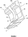
- Each rail portion 20 comprises an upper part in the form of a mushroom 22 and a base 24 extending along an axis YY perpendicular to the longitudinal axis XX of the rail portions 20.
- the upper part 22 and the base 24 being connected by a thinner surface 26.
- the weld 30 comprises a bead 32 in the form of a truncated pyramid.
- the length L1 of the small base (or upper base) of the truncated pyramid 32 extending along the longitudinal axis XX of the rail portions is between 45 mm and 55 mm, preferably approximately equal to 50 mm.
- the length L2 of the large base (or lower base) of the truncated pyramid 32 extending along the longitudinal axis XX of the rail portions is between 65 mm and 75 mm, preferably approximately equal to 70 mm.
- the length El represents the length of the small base of the truncated pyramid 32 extending along the YY axis perpendicular to the XX axis.
- the length E2 represents the length of the large base of the truncated pyramid 32 extending along the YY axis perpendicular to the XX axis.
- the weld 32 for securing the assembly 10 is obtained by casting liquid metal in a mold as described below.
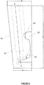
- the figure 6 illustrates a welding mold 40 according to the invention arranged around two portions of rail 20 before casting the welding metal in the mold 40.
- the welding mold 40 comprises a vent 42 extending substantially vertically in the ZZ direction so as to allow the pouring of the weld metal by gravity up to the welding volume V defining the contours of the weld between the two rail portions 20 .
- a passage 44 also allows the welding metal to be poured at the level of the head 22 of the portion of rails 20 so as to completely fill the welding volume V.
- the welding mold 40 comprises a curved outline 46 allowing the weld volume to widen in its lower half so as to receive a larger quantity of weld metal and thus allow said metal not to sag the rail portions 20. during its cooling.
- the two longitudinal portions of rail 20 to be welded are first placed end-to-end so as to leave a connecting space (not shown) between their ends 20e.
- An alignment device bench can be used to allow the two ends 20e of rail portions 20 to be placed opposite each other. Alignment consists of placing the two rail portions or ends 20 end to end so that the surfaces of the upper part 22 of the rail portions 20 are part of the same substantially horizontal plane and that their side surfaces oriented towards the inside of the track are part of a substantially vertical plane, the two planes being perpendicular to each other.
- the welding mold 40 defining the welding volume V between the two rail portions is then placed around said connecting space.
- a device for preheating the welding mold and the ends 20e of the two rail portions 20 is then installed so as to facilitate and improve the welding of the two rail portions 20
- the preheating can be preheating by induced air, by oxygen-propane, by air-gasoline or any other type of preheating known to allow such welding.
- a crucible in which is disposed an aluminothermic charge comprising the metal to be cast, is placed above the weld.
- the load is ignited so that an aluminothermic reaction occurs and the solder liquid metal then flows from the crucible by gravity into the weld volume.
- the mass of liquid metal is then, according to the invention, greater in the lower half of the welding volume than in its upper half.
- the mold is then removed to allow cooling of the cast metal which will then solidify so as to form the weld joining the two rail portions.
- the shape imparted to the weld by the mold according to the invention will make it possible, by the effect of traction in the metal, to raise the weld.
- the portion of the weld extending above the rail portions can thus be ground before the weld has completely cooled.
- width of the weld is meant the dimension of the weld along the longitudinal axis of the rails.
- the weld comprises a bead.
- a bead is created by the larger mass of liquid metal poured into the lower half of the welding volume and makes it possible to direct the setbacks in the vents, that is to say in the ducts of the mold, during the solidification of the metal.
- This bead is one of the elements which guarantees the internal health of the weld.
- the bead extends over most of the height of the weld.
- the bead is advantageously flared in its lower part.
- the bead comprises at least one portion in the form of a truncated pyramid.
- the dimensions of the small base of such a truncated pyramid are advantageously between 45 mm and 55 mm and the dimensions of its large base between 65 mm and 75 mm.
Landscapes
- Engineering & Computer Science (AREA)
- Mechanical Engineering (AREA)
- Architecture (AREA)
- Civil Engineering (AREA)
- Structural Engineering (AREA)
- Butt Welding And Welding Of Specific Article (AREA)
- Machines For Laying And Maintaining Railways (AREA)
Claims (6)
- Form zum Verschweißen von zwei länglichen Schienenabschnitten (20), die eingerichtet ist, um auf den Schienenabschnitten (20) angeordnet zu sein, und die ein Schweißvolumen (V) festlegt, das ausgelegt ist, um zum einen ein flüssiges Schweißmetall aufzunehmen und zum anderen derart, dass der von dem Schweißvolumen (V) in seiner unteren Hälfte festgelegte Raum größer ist als der von dem Schweißvolumen (V) in seinem oberen Teil festgelegte Raum, wobei die Form zum Verschweißen dadurch gekennzeichnet ist, dass das Schweißvolumen (V) mindestens im Bereich seiner unteren Hälfte zunehmend gemäß einer Richtung sowohl parallel als auch senkrecht zur Längsachse der Schienenabschnitte erweitert ist, so dass eine Schweißnaht (39) gebildet wird, deren Breite im Bereich ihrer Basis größer als in ihrem Mittelteil ist.
- Form nach Anspruch 1, wobei die untere Hälfte des Schweißvolumens (V) mindestens einen Abschnitt mit einem etwa kegelstumpfförmigen Querschnitt umfasst.
- Form nach Anspruch 2, wobei der Abschnitt ein Pyramidenstumpf ist.
- Verfahren zum Verschweißen von zwei länglichen Schienenabschnitten (20), umfassend:- einen Schritt des aneinandergefügten Anordnens der zwei zu verschweißenden länglichen Schienenabschnitte (20) derart, dass ein Verbindungsraum zwischen deren Enden (20e) ausgebildet wird,- einen Schritt des Platzierens einer Form zum Verschweißen (40) nach einem der Ansprüche 1 bis 3 um den Verbindungsraum, wobei die Form (40) ein Schweißvolumen (V) zwischen den zwei Schienenabschnitten (20) festlegt,- einen Schritt des Gießens eines flüssigen Schweißmetalls in das Schweißvolumen (V) derart, dass die gegossene Flüssigmetallmasse größer in der unteren Hälfte des Schweißvolumens (V) als in seiner oberen Hälfte ist,- einen Schritt des Verfestigens des gegossenen Metalls derart, dass die zwei Schienenabschnitte (20) verschweißt werden.
- Verfahren nach Anspruch 4, wobei das Verfahren nach dem Schritt des Gießens einen Schritt des Schleifens umfasst, der auf den Abschnitt der Schweißnaht begrenzt ist, der sich oberhalb der Schienenabschnitte (20) infolge der Erhöhung der Gesamtheit (10) erstreckt, die die zwei Schienenabschnitte (20) und die Schweißnaht (30) umfasst.
- Verfahren nach einem der Ansprüche 4 und 5, wobei das Verfahren einen einzigen Schleifschritt umfasst.
Applications Claiming Priority (2)
| Application Number | Priority Date | Filing Date | Title |
|---|---|---|---|
| FR1262725A FR2999966B1 (fr) | 2012-12-21 | 2012-12-21 | Procede et moule pour le soudage des extremites de deux portions de rail. |
| PCT/IB2013/060702 WO2014097043A1 (fr) | 2012-12-21 | 2013-12-06 | Procédé et moule pour le soudage des extrémités de deux portions de rail |
Publications (2)
| Publication Number | Publication Date |
|---|---|
| EP2934809A1 EP2934809A1 (de) | 2015-10-28 |
| EP2934809B1 true EP2934809B1 (de) | 2020-11-11 |
Family
ID=48083268
Family Applications (1)
| Application Number | Title | Priority Date | Filing Date |
|---|---|---|---|
| EP13818449.4A Active EP2934809B1 (de) | 2012-12-21 | 2013-12-06 | Verfahren zum verschweissen von schienenenden und form dafür |
Country Status (5)
| Country | Link |
|---|---|
| US (1) | US10011956B2 (de) |
| EP (1) | EP2934809B1 (de) |
| ES (1) | ES2836797T3 (de) |
| FR (1) | FR2999966B1 (de) |
| WO (1) | WO2014097043A1 (de) |
Families Citing this family (5)
| Publication number | Priority date | Publication date | Assignee | Title |
|---|---|---|---|---|
| WO2014032699A1 (de) * | 2012-08-28 | 2014-03-06 | Strothmann Machines & Handling GmbH | Schienensystem |
| FR3038920B1 (fr) * | 2015-07-17 | 2017-07-28 | Railtech Int | Piece de fond d'un moule de soudure de rails metalliques, moule correspondant et procede de soudure aluminothermique |
| WO2019067870A1 (en) | 2017-09-29 | 2019-04-04 | CF&I Steel L.P. D/B/A EVRAZ Rocky Mountain Steel | METHOD FOR ASSEMBLING STEEL RAILS WITH CONTROLLED WELDING HEAT DELIVERY |
| CN108149533B (zh) * | 2017-12-18 | 2020-05-22 | 中国铁道科学研究院金属及化学研究所 | 一种提高钢轨闪光焊接头强度的方法 |
| CN109396682A (zh) * | 2018-12-12 | 2019-03-01 | 超威电源有限公司 | 一种非金属蓄电池板栅极耳焊接装置及极耳焊接方法 |
Family Cites Families (4)
| Publication number | Priority date | Publication date | Assignee | Title |
|---|---|---|---|---|
| US4716836A (en) * | 1986-07-14 | 1988-01-05 | H. A. Schlatter Ag | Suspended rail welder |
| US5419484A (en) * | 1993-04-19 | 1995-05-30 | Radulescu; Stefam R. | Apparatus and process for aluminothermic welding |
| AT6690U3 (de) * | 2003-11-06 | 2004-11-25 | Plasser Bahnbaumasch Franz | Verfahren zum verschweissen von schienen eines gleises |
| FR2966172B1 (fr) * | 2010-10-15 | 2012-11-02 | Railtech Int | Procede et dispositif pour la soudure aluminothermique de rails |
-
2012
- 2012-12-21 FR FR1262725A patent/FR2999966B1/fr active Active
-
2013
- 2013-12-06 EP EP13818449.4A patent/EP2934809B1/de active Active
- 2013-12-06 WO PCT/IB2013/060702 patent/WO2014097043A1/fr not_active Ceased
- 2013-12-06 ES ES13818449T patent/ES2836797T3/es active Active
- 2013-12-06 US US14/653,833 patent/US10011956B2/en active Active
Non-Patent Citations (1)
| Title |
|---|
| None * |
Also Published As
| Publication number | Publication date |
|---|---|
| FR2999966B1 (fr) | 2014-12-05 |
| EP2934809A1 (de) | 2015-10-28 |
| ES2836797T3 (es) | 2021-06-28 |
| FR2999966A1 (fr) | 2014-06-27 |
| US10011956B2 (en) | 2018-07-03 |
| US20150361620A1 (en) | 2015-12-17 |
| WO2014097043A1 (fr) | 2014-06-26 |
Similar Documents
| Publication | Publication Date | Title |
|---|---|---|
| EP2934809B1 (de) | Verfahren zum verschweissen von schienenenden und form dafür | |
| EP3449059B1 (de) | Aluminothermische schweissform und reparaturverfahren | |
| FR3027037A1 (fr) | Porte-outil pour engin de chantier ou de travaux publics | |
| EP2337897B1 (de) | Vorrichtung zur wartung von schienenwegen | |
| FR3010688A1 (fr) | Outil permettant de remplacer le capot avant d'un vehicule automobile par un nouveau capot | |
| EP3852968B1 (de) | System zum ausrichten von schienenabschnitten für eine induktionsschweisseinheit | |
| CN209225162U (zh) | 一种煤矿轨道平巷运输用临时阻车器 | |
| EP0583181B1 (de) | Verfahren und Einrichtung zum Laserstahlschweissen von auf Stoss geführten Stahlblechen | |
| EP1854707A1 (de) | Anschlussstück für einen Längsträger für ein Kraftfahrzeug und Längsträger, der ein solches Anschlussstück umfasst | |
| EP3260600A1 (de) | Verfahren zum reparieren einer eisenbahnschiene mithilfe einer reparaturform | |
| FR3008373A1 (fr) | Procede de montage de la face avant d’un vehicule | |
| FR2866038A1 (fr) | Dispositif d'assemblage de deux modules de barriere de securite prefabriques en beton, barriere de securite routiere ou autoroutiere en comportant application et module pour une telle barriere | |
| EP1650141A2 (de) | Verfahren zur Montage einer Lagerstruktur mittels einer Hebevorrichtung | |
| EP4452543B1 (de) | Form zum aluminothermischen schweissen von schienen | |
| FR3033289A1 (fr) | "procede de renforcement de la fixation d'une traverse sur un bras longitudinal d'un essieu semi rigide" | |
| FR3025813A1 (fr) | Selle de support de rail de voie ferree | |
| EP2757200B1 (de) | Gerät zum Herausziehen oder Einrammen eines Gegenstands (wie Pfahl oder Rohr) in den Boden, und entsprechendes Verfahren | |
| EP3200971B1 (de) | Zweiteilige anordnung einer beleuchtungsvorrichtung durch spiegelschweissen über expanderrippen | |
| EP3252002B1 (de) | Spannsystem für die karosserie eines fahrzeugs auf einem hubtisch | |
| EP4186811A1 (de) | Device for handling a railway vehicle coupling and associated method | |
| EP3325719B1 (de) | Basisteil einer form zum verschweissen von metallschienen | |
| EP3326885B1 (de) | Keil zum wiedereingleisen eines auf schienen geführten fahrzeugs, und entsprechendes verfahren zur wiedereingleisung | |
| EP3006625B1 (de) | Einfassungsplatte für einen bahnsteig | |
| CN205189039U (zh) | 一种具有扶手的作业车辆 | |
| EP3152100B1 (de) | Anordnung zum halten eines reservereifens in einem unterboden, kraftfahrzeug mit solch einer anordnung, verfahren zur herstellung derselben und verfahren zur montage einer derartigen anordnung an einem fahrzeug |
Legal Events
| Date | Code | Title | Description |
|---|---|---|---|
| PUAI | Public reference made under article 153(3) epc to a published international application that has entered the european phase |
Free format text: ORIGINAL CODE: 0009012 |
|
| 17P | Request for examination filed |
Effective date: 20150604 |
|
| AK | Designated contracting states |
Kind code of ref document: A1 Designated state(s): AL AT BE BG CH CY CZ DE DK EE ES FI FR GB GR HR HU IE IS IT LI LT LU LV MC MK MT NL NO PL PT RO RS SE SI SK SM TR |
|
| AX | Request for extension of the european patent |
Extension state: BA ME |
|
| DAX | Request for extension of the european patent (deleted) | ||
| RAP1 | Party data changed (applicant data changed or rights of an application transferred) |
Owner name: SNCF RESEAU |
|
| RAP1 | Party data changed (applicant data changed or rights of an application transferred) |
Owner name: SNCF RESEAU |
|
| RAP1 | Party data changed (applicant data changed or rights of an application transferred) |
Owner name: SNCF RESEAU |
|
| STAA | Information on the status of an ep patent application or granted ep patent |
Free format text: STATUS: EXAMINATION IS IN PROGRESS |
|
| 17Q | First examination report despatched |
Effective date: 20181108 |
|
| 17Q | First examination report despatched |
Effective date: 20190515 |
|
| GRAP | Despatch of communication of intention to grant a patent |
Free format text: ORIGINAL CODE: EPIDOSNIGR1 |
|
| STAA | Information on the status of an ep patent application or granted ep patent |
Free format text: STATUS: GRANT OF PATENT IS INTENDED |
|
| INTG | Intention to grant announced |
Effective date: 20200211 |
|
| GRAJ | Information related to disapproval of communication of intention to grant by the applicant or resumption of examination proceedings by the epo deleted |
Free format text: ORIGINAL CODE: EPIDOSDIGR1 |
|
| STAA | Information on the status of an ep patent application or granted ep patent |
Free format text: STATUS: EXAMINATION IS IN PROGRESS |
|
| INTC | Intention to grant announced (deleted) | ||
| GRAP | Despatch of communication of intention to grant a patent |
Free format text: ORIGINAL CODE: EPIDOSNIGR1 |
|
| STAA | Information on the status of an ep patent application or granted ep patent |
Free format text: STATUS: GRANT OF PATENT IS INTENDED |
|
| INTG | Intention to grant announced |
Effective date: 20200603 |
|
| GRAS | Grant fee paid |
Free format text: ORIGINAL CODE: EPIDOSNIGR3 |
|
| GRAA | (expected) grant |
Free format text: ORIGINAL CODE: 0009210 |
|
| STAA | Information on the status of an ep patent application or granted ep patent |
Free format text: STATUS: THE PATENT HAS BEEN GRANTED |
|
| AK | Designated contracting states |
Kind code of ref document: B1 Designated state(s): AL AT BE BG CH CY CZ DE DK EE ES FI FR GB GR HR HU IE IS IT LI LT LU LV MC MK MT NL NO PL PT RO RS SE SI SK SM TR |
|
| REG | Reference to a national code |
Ref country code: GB Ref legal event code: FG4D Free format text: NOT ENGLISH |
|
| REG | Reference to a national code |
Ref country code: CH Ref legal event code: EP |
|
| REG | Reference to a national code |
Ref country code: AT Ref legal event code: REF Ref document number: 1332986 Country of ref document: AT Kind code of ref document: T Effective date: 20201115 |
|
| REG | Reference to a national code |
Ref country code: DE Ref legal event code: R096 Ref document number: 602013074023 Country of ref document: DE |
|
| REG | Reference to a national code |
Ref country code: IE Ref legal event code: FG4D Free format text: LANGUAGE OF EP DOCUMENT: FRENCH |
|
| REG | Reference to a national code |
Ref country code: AT Ref legal event code: MK05 Ref document number: 1332986 Country of ref document: AT Kind code of ref document: T Effective date: 20201111 |
|
| PG25 | Lapsed in a contracting state [announced via postgrant information from national office to epo] |
Ref country code: PT Free format text: LAPSE BECAUSE OF FAILURE TO SUBMIT A TRANSLATION OF THE DESCRIPTION OR TO PAY THE FEE WITHIN THE PRESCRIBED TIME-LIMIT Effective date: 20210311 Ref country code: NO Free format text: LAPSE BECAUSE OF FAILURE TO SUBMIT A TRANSLATION OF THE DESCRIPTION OR TO PAY THE FEE WITHIN THE PRESCRIBED TIME-LIMIT Effective date: 20210211 Ref country code: FI Free format text: LAPSE BECAUSE OF FAILURE TO SUBMIT A TRANSLATION OF THE DESCRIPTION OR TO PAY THE FEE WITHIN THE PRESCRIBED TIME-LIMIT Effective date: 20201111 Ref country code: RS Free format text: LAPSE BECAUSE OF FAILURE TO SUBMIT A TRANSLATION OF THE DESCRIPTION OR TO PAY THE FEE WITHIN THE PRESCRIBED TIME-LIMIT Effective date: 20201111 Ref country code: GR Free format text: LAPSE BECAUSE OF FAILURE TO SUBMIT A TRANSLATION OF THE DESCRIPTION OR TO PAY THE FEE WITHIN THE PRESCRIBED TIME-LIMIT Effective date: 20210212 |
|
| PG25 | Lapsed in a contracting state [announced via postgrant information from national office to epo] |
Ref country code: LV Free format text: LAPSE BECAUSE OF FAILURE TO SUBMIT A TRANSLATION OF THE DESCRIPTION OR TO PAY THE FEE WITHIN THE PRESCRIBED TIME-LIMIT Effective date: 20201111 Ref country code: IS Free format text: LAPSE BECAUSE OF FAILURE TO SUBMIT A TRANSLATION OF THE DESCRIPTION OR TO PAY THE FEE WITHIN THE PRESCRIBED TIME-LIMIT Effective date: 20210311 Ref country code: AT Free format text: LAPSE BECAUSE OF FAILURE TO SUBMIT A TRANSLATION OF THE DESCRIPTION OR TO PAY THE FEE WITHIN THE PRESCRIBED TIME-LIMIT Effective date: 20201111 Ref country code: BG Free format text: LAPSE BECAUSE OF FAILURE TO SUBMIT A TRANSLATION OF THE DESCRIPTION OR TO PAY THE FEE WITHIN THE PRESCRIBED TIME-LIMIT Effective date: 20210211 |
|
| REG | Reference to a national code |
Ref country code: LT Ref legal event code: MG9D |
|
| REG | Reference to a national code |
Ref country code: ES Ref legal event code: FG2A Ref document number: 2836797 Country of ref document: ES Kind code of ref document: T3 Effective date: 20210628 |
|
| PG25 | Lapsed in a contracting state [announced via postgrant information from national office to epo] |
Ref country code: HR Free format text: LAPSE BECAUSE OF FAILURE TO SUBMIT A TRANSLATION OF THE DESCRIPTION OR TO PAY THE FEE WITHIN THE PRESCRIBED TIME-LIMIT Effective date: 20201111 |
|
| PG25 | Lapsed in a contracting state [announced via postgrant information from national office to epo] |
Ref country code: LT Free format text: LAPSE BECAUSE OF FAILURE TO SUBMIT A TRANSLATION OF THE DESCRIPTION OR TO PAY THE FEE WITHIN THE PRESCRIBED TIME-LIMIT Effective date: 20201111 Ref country code: RO Free format text: LAPSE BECAUSE OF FAILURE TO SUBMIT A TRANSLATION OF THE DESCRIPTION OR TO PAY THE FEE WITHIN THE PRESCRIBED TIME-LIMIT Effective date: 20201111 Ref country code: SK Free format text: LAPSE BECAUSE OF FAILURE TO SUBMIT A TRANSLATION OF THE DESCRIPTION OR TO PAY THE FEE WITHIN THE PRESCRIBED TIME-LIMIT Effective date: 20201111 Ref country code: EE Free format text: LAPSE BECAUSE OF FAILURE TO SUBMIT A TRANSLATION OF THE DESCRIPTION OR TO PAY THE FEE WITHIN THE PRESCRIBED TIME-LIMIT Effective date: 20201111 Ref country code: CZ Free format text: LAPSE BECAUSE OF FAILURE TO SUBMIT A TRANSLATION OF THE DESCRIPTION OR TO PAY THE FEE WITHIN THE PRESCRIBED TIME-LIMIT Effective date: 20201111 Ref country code: SM Free format text: LAPSE BECAUSE OF FAILURE TO SUBMIT A TRANSLATION OF THE DESCRIPTION OR TO PAY THE FEE WITHIN THE PRESCRIBED TIME-LIMIT Effective date: 20201111 |
|
| REG | Reference to a national code |
Ref country code: CH Ref legal event code: PL |
|
| REG | Reference to a national code |
Ref country code: DE Ref legal event code: R097 Ref document number: 602013074023 Country of ref document: DE |
|
| PG25 | Lapsed in a contracting state [announced via postgrant information from national office to epo] |
Ref country code: DK Free format text: LAPSE BECAUSE OF FAILURE TO SUBMIT A TRANSLATION OF THE DESCRIPTION OR TO PAY THE FEE WITHIN THE PRESCRIBED TIME-LIMIT Effective date: 20201111 Ref country code: MC Free format text: LAPSE BECAUSE OF FAILURE TO SUBMIT A TRANSLATION OF THE DESCRIPTION OR TO PAY THE FEE WITHIN THE PRESCRIBED TIME-LIMIT Effective date: 20201111 |
|
| PLBE | No opposition filed within time limit |
Free format text: ORIGINAL CODE: 0009261 |
|
| STAA | Information on the status of an ep patent application or granted ep patent |
Free format text: STATUS: NO OPPOSITION FILED WITHIN TIME LIMIT |
|
| REG | Reference to a national code |
Ref country code: NL Ref legal event code: FP |
|
| 26N | No opposition filed |
Effective date: 20210812 |
|
| PG25 | Lapsed in a contracting state [announced via postgrant information from national office to epo] |
Ref country code: AL Free format text: LAPSE BECAUSE OF FAILURE TO SUBMIT A TRANSLATION OF THE DESCRIPTION OR TO PAY THE FEE WITHIN THE PRESCRIBED TIME-LIMIT Effective date: 20201111 Ref country code: LU Free format text: LAPSE BECAUSE OF NON-PAYMENT OF DUE FEES Effective date: 20201206 Ref country code: IE Free format text: LAPSE BECAUSE OF NON-PAYMENT OF DUE FEES Effective date: 20201206 |
|
| PG25 | Lapsed in a contracting state [announced via postgrant information from national office to epo] |
Ref country code: SI Free format text: LAPSE BECAUSE OF FAILURE TO SUBMIT A TRANSLATION OF THE DESCRIPTION OR TO PAY THE FEE WITHIN THE PRESCRIBED TIME-LIMIT Effective date: 20201111 Ref country code: CH Free format text: LAPSE BECAUSE OF NON-PAYMENT OF DUE FEES Effective date: 20201231 Ref country code: LI Free format text: LAPSE BECAUSE OF NON-PAYMENT OF DUE FEES Effective date: 20201231 |
|
| PG25 | Lapsed in a contracting state [announced via postgrant information from national office to epo] |
Ref country code: IS Free format text: LAPSE BECAUSE OF FAILURE TO SUBMIT A TRANSLATION OF THE DESCRIPTION OR TO PAY THE FEE WITHIN THE PRESCRIBED TIME-LIMIT Effective date: 20210311 Ref country code: TR Free format text: LAPSE BECAUSE OF FAILURE TO SUBMIT A TRANSLATION OF THE DESCRIPTION OR TO PAY THE FEE WITHIN THE PRESCRIBED TIME-LIMIT Effective date: 20201111 Ref country code: MT Free format text: LAPSE BECAUSE OF FAILURE TO SUBMIT A TRANSLATION OF THE DESCRIPTION OR TO PAY THE FEE WITHIN THE PRESCRIBED TIME-LIMIT Effective date: 20201111 Ref country code: CY Free format text: LAPSE BECAUSE OF FAILURE TO SUBMIT A TRANSLATION OF THE DESCRIPTION OR TO PAY THE FEE WITHIN THE PRESCRIBED TIME-LIMIT Effective date: 20201111 |
|
| PG25 | Lapsed in a contracting state [announced via postgrant information from national office to epo] |
Ref country code: MK Free format text: LAPSE BECAUSE OF FAILURE TO SUBMIT A TRANSLATION OF THE DESCRIPTION OR TO PAY THE FEE WITHIN THE PRESCRIBED TIME-LIMIT Effective date: 20201111 |
|
| P01 | Opt-out of the competence of the unified patent court (upc) registered |
Effective date: 20230530 |
|
| PGFP | Annual fee paid to national office [announced via postgrant information from national office to epo] |
Ref country code: NL Payment date: 20251127 Year of fee payment: 13 |
|
| PGFP | Annual fee paid to national office [announced via postgrant information from national office to epo] |
Ref country code: GB Payment date: 20251229 Year of fee payment: 13 |
|
| PGFP | Annual fee paid to national office [announced via postgrant information from national office to epo] |
Ref country code: IT Payment date: 20251211 Year of fee payment: 13 |
|
| PGFP | Annual fee paid to national office [announced via postgrant information from national office to epo] |
Ref country code: FR Payment date: 20251230 Year of fee payment: 13 |
|
| PGFP | Annual fee paid to national office [announced via postgrant information from national office to epo] |
Ref country code: BE Payment date: 20251226 Year of fee payment: 13 |
|
| PGFP | Annual fee paid to national office [announced via postgrant information from national office to epo] |
Ref country code: SE Payment date: 20251218 Year of fee payment: 13 |
|
| PGFP | Annual fee paid to national office [announced via postgrant information from national office to epo] |
Ref country code: PL Payment date: 20251125 Year of fee payment: 13 |
|
| PGFP | Annual fee paid to national office [announced via postgrant information from national office to epo] |
Ref country code: ES Payment date: 20260112 Year of fee payment: 13 |
|
| PGFP | Annual fee paid to national office [announced via postgrant information from national office to epo] |
Ref country code: DE Payment date: 20251231 Year of fee payment: 13 |