EP2940723B1 - Endeffektor - Google Patents
Endeffektor Download PDFInfo
- Publication number
- EP2940723B1 EP2940723B1 EP13868539.1A EP13868539A EP2940723B1 EP 2940723 B1 EP2940723 B1 EP 2940723B1 EP 13868539 A EP13868539 A EP 13868539A EP 2940723 B1 EP2940723 B1 EP 2940723B1
- Authority
- EP
- European Patent Office
- Prior art keywords
- portions
- link
- slider
- link member
- axis line
- Prior art date
- Legal status (The legal status is an assumption and is not a legal conclusion. Google has not performed a legal analysis and makes no representation as to the accuracy of the status listed.)
- Active
Links
Images







Classifications
-
- H—ELECTRICITY
- H10—SEMICONDUCTOR DEVICES; ELECTRIC SOLID-STATE DEVICES NOT OTHERWISE PROVIDED FOR
- H10P—GENERIC PROCESSES OR APPARATUS FOR THE MANUFACTURE OR TREATMENT OF DEVICES COVERED BY CLASS H10
- H10P72/00—Handling or holding of wafers, substrates or devices during manufacture or treatment thereof
- H10P72/30—Handling or holding of wafers, substrates or devices during manufacture or treatment thereof for conveying, e.g. between different workstations
- H10P72/33—Handling or holding of wafers, substrates or devices during manufacture or treatment thereof for conveying, e.g. between different workstations into and out of processing chamber
- H10P72/3302—Mechanical parts of transfer devices
-
- B—PERFORMING OPERATIONS; TRANSPORTING
- B25—HAND TOOLS; PORTABLE POWER-DRIVEN TOOLS; MANIPULATORS
- B25J—MANIPULATORS; CHAMBERS PROVIDED WITH MANIPULATION DEVICES
- B25J11/00—Manipulators not otherwise provided for
- B25J11/0095—Manipulators transporting wafers
-
- H—ELECTRICITY
- H10—SEMICONDUCTOR DEVICES; ELECTRIC SOLID-STATE DEVICES NOT OTHERWISE PROVIDED FOR
- H10P—GENERIC PROCESSES OR APPARATUS FOR THE MANUFACTURE OR TREATMENT OF DEVICES COVERED BY CLASS H10
- H10P72/00—Handling or holding of wafers, substrates or devices during manufacture or treatment thereof
- H10P72/30—Handling or holding of wafers, substrates or devices during manufacture or treatment thereof for conveying, e.g. between different workstations
- H10P72/34—Handling or holding of wafers, substrates or devices during manufacture or treatment thereof for conveying, e.g. between different workstations the wafers being stored in a carrier, involving loading and unloading
- H10P72/3402—Mechanical parts of transfer devices
-
- H—ELECTRICITY
- H10—SEMICONDUCTOR DEVICES; ELECTRIC SOLID-STATE DEVICES NOT OTHERWISE PROVIDED FOR
- H10P—GENERIC PROCESSES OR APPARATUS FOR THE MANUFACTURE OR TREATMENT OF DEVICES COVERED BY CLASS H10
- H10P72/00—Handling or holding of wafers, substrates or devices during manufacture or treatment thereof
- H10P72/30—Handling or holding of wafers, substrates or devices during manufacture or treatment thereof for conveying, e.g. between different workstations
- H10P72/34—Handling or holding of wafers, substrates or devices during manufacture or treatment thereof for conveying, e.g. between different workstations the wafers being stored in a carrier, involving loading and unloading
- H10P72/3404—Storage means
-
- H—ELECTRICITY
- H10—SEMICONDUCTOR DEVICES; ELECTRIC SOLID-STATE DEVICES NOT OTHERWISE PROVIDED FOR
- H10P—GENERIC PROCESSES OR APPARATUS FOR THE MANUFACTURE OR TREATMENT OF DEVICES COVERED BY CLASS H10
- H10P72/00—Handling or holding of wafers, substrates or devices during manufacture or treatment thereof
- H10P72/30—Handling or holding of wafers, substrates or devices during manufacture or treatment thereof for conveying, e.g. between different workstations
- H10P72/34—Handling or holding of wafers, substrates or devices during manufacture or treatment thereof for conveying, e.g. between different workstations the wafers being stored in a carrier, involving loading and unloading
- H10P72/3411—Handling or holding of wafers, substrates or devices during manufacture or treatment thereof for conveying, e.g. between different workstations the wafers being stored in a carrier, involving loading and unloading involving loading and unloading of wafers
- H10P72/3412—Batch transfer of wafers
-
- H—ELECTRICITY
- H10—SEMICONDUCTOR DEVICES; ELECTRIC SOLID-STATE DEVICES NOT OTHERWISE PROVIDED FOR
- H10P—GENERIC PROCESSES OR APPARATUS FOR THE MANUFACTURE OR TREATMENT OF DEVICES COVERED BY CLASS H10
- H10P72/00—Handling or holding of wafers, substrates or devices during manufacture or treatment thereof
- H10P72/70—Handling or holding of wafers, substrates or devices during manufacture or treatment thereof for supporting or gripping
- H10P72/76—Handling or holding of wafers, substrates or devices during manufacture or treatment thereof for supporting or gripping using mechanical means, e.g. clamps or pinches
- H10P72/7602—Handling or holding of wafers, substrates or devices during manufacture or treatment thereof for supporting or gripping using mechanical means, e.g. clamps or pinches the wafers being placed on a robot blade or gripped by a gripper for conveyance
Definitions
- the present invention relates to an end effector device, particularly an end effector device provided with a pitch changing mechanism which changes a vertical pitch of a plurality of plate members arranged vertically at intervals.
- Patent Document 1 A device for conveying a substrate, such as this semiconductor wafer, is disclosed in Patent Document 1 to be known.
- an arm is provided to a case so as to be rotatable in a horizontal plane, and a hand, on which a substrate is placed, is provided to the distal end portion of this arm.
- a motor as a driving source is disposed in the case, and from the motor to the hand, power transmitting members, such as a pulley and a belt, are disposed in a horizontal direction in multiple stages. Therefore, the distance from the motor to the hand in the horizontal plane is long.
- the power transmitting members are sealingly stored in the case and the hand.
- the power transmitting members When power is transmitted from the motor to the hand, the power transmitting members may rub each other so as to cause particles, such as powder dusts. However, the power transmitting members are sealingly stored in the hand, the particles are prevented from scattering from the inside of the case or the hand so that the particles do not adhere to the plate member.
- Patent Document 2 discloses a conveyance device provided with a plurality of substrate holding members of plate shape which are disposed in the vertical direction with intervals, the intervals being able to be changed.
- a plurality of substrates are stored in a cassette with intervals in the vertical direction, and when the plurality of substrates are conveyed from the cassette to another spot, their vertical pitch may be changed. Therefore, according to this conveyance device, a plurality of substrates can be conveyed with their pitch coverted.
- a substrate conveyance robot which has an excellent performance of conveying a substrate, is used for conveying a substrate.
- This substrate conveyance robot is required to prevent particles generated from its driving mechanism from adhering to the substrate which is being conveyed, as described in Patent Document 1.
- Patent Document 1 cannot convey a plurality of substrates at the same time, and the pitch thereof cannot be changed.
- a plurality of substrate holding members of plate shape corresponding to a so-called hand of a substrate conveyance robot are disposed in the vertical direction so as to be vertically movable. Therefore, by vertically moving the plurality of substrate holding members, the vertical pitch of the substrates held by the substrate holding members can be changed.
- the driving mechanism for vertically moving the substrate holding members are disposed on the lateral side of the substrate holding members so as to be exposed with respect to the substrate holding members. Therefore, there is a possibility that the particles generated in the driving mechanism may adhere to the substrates which are held by the substrate holding members.
- the mechanism for changing the pitch of the substrates is large-scale.
- EP 2 743 975 A1 filed before but published after the relevant date of this invention discloses another end-effector device attached to a tip end portion of a robot arm comprising a hand having a storing device, holding portions, linearly moving portions and drive portions.
- An object of the present invention is to provide an end effector device which has a pitch conversion mechanism for holding a plurality of plate members and changing the intervals of the plate members held by the same, the end effector device being capable of alleviating contamination of the plate members by particles which are generated in the pitch conversion mechanism.
- An end effector device includes: a hand having a storing space; and a plurality of holding portions provided to the hand and configured to hold parts of each of a plurality of plate members so as to hold the plurality of plate members respectively, the parts being different from each other in a peripheral direction of a peripheral edge portion of each plate member respectively, wherein each of the holding portions includes a plurality of receiving portions which respectively receive peripheral edge portions of the plurality of plate members so that the plurality of plate members are arranged substantially parallel with one plane and at an interval mutually in a first direction which is substantially perpendicular to the one plane, and a pitch changing mechanism configured to linearly move the plurality of receiving portions in the first direction respectively so as to change the interval, wherein a plurality of linearly moving portions configured to respectively move linearly integrally with the plurality of receiving portions of the pitch changing mechanism are provided to the hand so as to be exposed outside of the hand, and wherein a plurality of drive portions configured to drive the plurality of linearly moving portions of the pitch changing
- the pitch conversion mechanism is divided into the linearly moving portions and the drive portions.
- the linearly moving portions are exposed outside of the hand, the linearly moving portions linearly move together with the receiving portions for receiving the plate members so that the plate members do not rub, and there is no actuation mechanism in the inside, as a result, no particle is generated.
- the drive portion include an actuation mechanism in its inside so that particles may be generated, but it is spaced from the receiving portions for receiving the plate members in the first direction as the arrangement direction of the plate members, and is stored in the inside of the hand. Thereby, the plate members can be prevented from being contaminated by the particles due to the pitch conversion mechanism.
- the drive portions of the pitch conversion mechanism exist just close to the receiving portions. Thereby, the accuracy of movement for changing the intervals of the receiving portions can be enhanced.
- the hand includes a hollow body portion formed so as to extend in a second direction substantially parallel with the one plane, and a hollow movable portion connected to a proximal end portion of the body portion so as to be capable of advancing and retreating in the second direction, and the plurality of holding portions include first holding portions provided to a distal end portion of the body portion and second holding portions provided to the movable portion.
- the plate members are held by the receiving portions of the first holding portions provided to the distal end portion of the body portion of the hand and the receiving portions of the second holding portions provided to the movable portion of the hand so that the plate members are stably held.
- the peripheral edge portions of the plurality of plate members are gripped by the first holding portions and the second holding portions so as to be held, and when the movable portion has retreated, the peripheral edge portions of the plurality of plate members are released from the second holding portions.
- the plurality of plate members are gripped by the first holding portions and the second holding portions so that the plate members can be prevented from displacing when the hand is moved.
- the present invention can provide an end effector device which has a pitch conversion mechanism for holding a plurality of plate members and changing the intervals of the plate members held by the same, the end effector device being capable of alleviating contamination of the plate members by particles which are generated in the pitch conversion mechanism.
- the present invention relates to an end effector mounted to a distal end portion of an arm of a plate member conveying robot.
- the plate member conveying robot will be generally described.
- a disk-shaped semiconductor wafer is exemplified as a plate member conveyed by the plate member conveying robot, the plate member is not limited to the semiconductor wafer.
- the plate member may be a thin liquid crystal display processed by a semiconductor process, or a glass substrate for organic EL display.
- the semiconductor wafer is a substrate material of a semiconductor device, including a silicon wafer, a silicon carbide wafer, a sapphire wafer, or the like.
- the plate member conveying robot includes a pitch changing mechanism changing a vertical pitch of adjacent semiconductor wafers when conveying a plurality of semiconductor wafers from a FOUP to another spot for performing a predetermined process as hereunder.
- the pitch changing mechanism performs the operation of widening a vertical pitch of adjacent semiconductor wafers when conveying a plurality of semiconductor wafers from a FOUP to another spot.
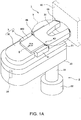
- FIGs. 1A and 1B are an entire perspective view of a plate member conveying robot 2, FIG. 1A illustrating a state that a cover 600 described later is mounted and FIG. 1B illustrating a state that the cover 600 is removed, respectively.
- the plate member conveying robot 2 is a robot arranged in a semiconductor processing equipment so as to convey a plurality of semiconductor wafers, for example, being so called a horizontal articulated robot.
- the plate member conveying robot 2 is configured by a supporting base 22 fixed to a floor surface, an arm supporting shaft 23 vertically movable and turnably provided on the supporting base 22, and an arm 20 extending in the horizontal direction whose one end portion is rotatably mounted to an upper end portion of the arm supporting shaft 23, for example.
- One end portion of a base 21 extending in the horizontal direction overlapping with the arm 20 is provided to the other end portion of the arm 20 so as to rotate in the horizontal plane via a shaft body 24 extending vertically. Operations of the plate member conveying robot 2 and an end effector device 1 which will be described later are controlled by a control device which is not shown.
- a hand 3 formed to be thick is provided on the base 21.
- a FOUP 90 storing a plurality of semiconductor wafers 9 vertically at intervals is provided in the semiconductor processing equipment opposing to a distal end portion of the hand 3.
- the arm 20 rotates in the horizontal plane about the arm supporting shaft 23 as the center and also the base 21 rotates about the shaft body 24 as the center. Thereby, the hand 3 can approach and be move away with respect to the FOUP 90.
- a moving direction of the hand 3 toward the FOUP 90 is referred to as a forward direction
- a moving direction that the hand 3 is moved away from the FOUP 90 is referred to as a rearward direction.
- a direction perpendicular to the forward and rearward direction in the horizontal plane is referred to as a left and right direction.
- movements of the hand 3 in the forward direction and the rearward direction are referred to as advance and retreat, respectively.
- the semiconductor processing equipment may be configured by a processing device and a conveying device.
- the processing device is a device performing a predetermined process to semiconductor wafers.
- the conveying device is a device conveying semiconductor wafers between the FOUP 90 and the processing device.
- the plate member conveying robot 2 may be arranged in the processing device or may be arranged in the conveying device.
- a mechanism which drives the hand 3 is referred to as a hand drive mechanism.
- the hand drive mechanism is configured by the arm 20, base 21, supporting base 22, supporting shaft 23, and the shaft body 24.
- the hand drive mechanism is not limited to this configuration, and various configurations capable of conveying semiconductor wafers by driving the hand 3 can be employed. For example, configurations of orthogonal coordinate type, cylindrical coordinate type, articulated type, and parallel link type can be employed.
- the hand 3 is provided with a body portion 30 fixed to the base 21 so that the longitudinal direction thereof is along the base 21, and two movable portions 31 positioned on both sides of the center portion in the longitudinal direction of the body portion 30 and provided so as to advance and retreat on the base 21. Both the body portion 30 and the movable portion 31 are formed to be hollow, and storing spaces consisting of the hollow part are formed therein.
- An opposed surface 32 horizontal to an area for holding a semiconductor wafer 9 is formed on a distal end portion of the body portion 30, and a plurality of, four in FIGs. 1A and 1B , holding portions each of which holds peripheral edge portions of the semiconductor wafers 9 are provided around the opposed surface 32.
- the holding portions are configured by two first holding portions 4A provided so as to be separated from each other on the left and right on the distal end portion of the body portion 30 and two second holding portions 4B provided on distal end portions of the movable portions 31, respectively. Namely, parts different from each other of the peripheral edge portion of the semiconductor wafer 9 are held by a plurality of first holding portions 4A and second holding portions 4B.
- the main portion of the end effector 1 to be mounted on the distal end portion of the plate member conveying robot 2 is configured by the hand 3 and the both holding portions 4A, 4B.
- a cover 600 is provided on the center portion in the longitudinal direction of the body portion 30, and a four-joint link mechanism 6 in a parallelogram shape is provided inside of the cover 600, as illustrated in FIG. 1B .
- FIGs. 2A and 2B are plan views illustrating positional relations between the body portion 30 and the movable portion 31.
- the four-joint link mechanism 6 on the body portion 30 is configured by connecting four small link plates 60 with four connecting shafts 61, 61a, 61b so as to form a parallelogram shape.
- An actuator 100 is provided in front of the four-joint link mechanism 6, and the actuator 100 is configured in a housing 110, providing a piston 120 movably in the forward and rearward direction.
- the rearmost connecting shaft is fixed to the body portion 30, and this connecting shaft is referred to as a fixed connecting shaft 61a.
- the piston 120 of the actuator 100 is mounted to a connecting shaft positioned on a diagonal of the four-joint link mechanism 6 with respect to the fixed connecting shaft 61a. Thereby, the connecting shaft is driven forward and rearward.
- This connecting shaft is referred to as a driven connecting shaft 61b.
- two connecting shafts 61 other than the fixed connecting shaft 61a and the driven connecting shaft 61b are connected to the movable portion 31 via a connecting plate 62 extending to the left and right respectively.
- Two turning auxiliary link plates 63 connecting the movable portion 31 movably forward and rearward with respect to the body portion 30 are provided between the body portion 30 and each movable portion 31 so as to be in parallel with each other and separated forward and rearward from each other. Namely, the body portion 30, movable portion 31, and two turning auxiliary link plates 63 are connected to one another so as to configure a parallel link.
- a mechanism driving the second holding portion 4B with respect to the body portion 30 is referred to as a second holding portion drive mechanism.
- the second holding portion drive mechanism is configured by the four-joint link mechanism 6, the connecting plate 62, the turning auxiliary link plate 63, and the movable portion 31 mentioned above in the embodiment.
- the second holding portion drive mechanism is not limited to this configuration, and an actuator such as an air cylinder in which a piston is fixed to the body portion 30 and a housing is fixed to the second holding portion 4B can be employed.
- the movable portions 31 are in an advanced state and the second holding portions 4B hold the peripheral edge portion of the semiconductor wafer 9.
- the driven connecting shaft 61b moves to the rear.
- the two small link plates 60 positioned on the both sides of the fixed connecting shaft 61a turn so as to open from each other.
- the connecting plates 62 arcuately move to the rear about the fixed connecting shaft 61a as the center.
- the small link plates 60 and the turning auxiliary link plates 63 are in parallel with each other, and the small link plates 60 and the turning auxiliary link plates 63 configure a parallelogram.
- the movable portions 31 are restricted by the turning auxiliary link plates 63 and retreat in a rotational direction (direction of arrow X in FIG. 2A ) of the turning auxiliary link plates 63, respectively.
- the second holding portions 4B move away from the peripheral edge portion of the semiconductor wafer 9 so as to release the holding of the semiconductor wafer 9.
- the movable portions 31 rotate in the advance direction and the second holding portions 4B hold the peripheral portion of the semiconductor wafer 9 as illustrated in FIG. 2A .
- the actuator 100 is actuated so as to rotate the movable portions 31 in the retreat direction as illustrated in FIG. 2B .
- the second holding portions 4B move away from the peripheral edge portion of the semiconductor wafer 9 so as to release the holding of the semiconductor wafer 9.
- the small link plates 60 When the small link plates 60 rotate, the small link plates 60 may rub each other, causing particles as a result.
- the cover 600 is put on the four-joint link mechanism 6 in order to prevent the particles from scattering. Accordingly, the cover 600 does not need to be provided when the four-joint link mechanism 6 is stored in the body portion 30.
- the first holding portions 4A are not displaced relatively in the horizontal direction with respect to the body portion 30.
- the second holding portions 4B are displaced relatively in the horizontal direction, specifically in the forward and rearward direction with respect to the body portion 30 of the hand 3.
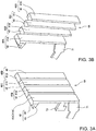
- FIGs. 3A and 3B are perspective views of the first holding portion 4A. Although FIGs. 3A and 3B illustrate states of the first holding portion 4A on the left side of the body portion 30 in views from the front, the first holding portion on the right side of the body portion 30 has the same configuration.
- the first holding portion 4A includes four linearly moving bodies 40A, 40B, 40C, 40D continued along the peripheral edge portion of the semiconductor wafer 9 corresponding to the number of semiconductor wafers 9 to be gripped and vertically moved and a pitch changing mechanism described later for elevating each linearly moving portions 40A, 40B, 40C, 40D by respective heights different from each other. While the number of semiconductor wafers 9 to be gripped is five, the number of the linearly moving bodies 40A, 40B, 40C, 40D is four. This is because the lowermost semiconductor wafer 9 is supported by a receiving portion 42 fixed on the hand 3 and is not elevated.
- the four linearly moving bodies 40A, 40B, 40C, 40D are provided so as to be moved vertically, and each linearly moving body 40A, 40B, 40C, 40D is configured so as to provide the receiving portion 42 for supporting the lower surface of the peripheral edge portion of the semiconductor wafer 9 to the distal end portion, namely the upper end portion of each of linearly moving portions 41A, 41B, 41C, 41D which is a vertically elongated plate material.
- the receiving portion 42 is formed so that an abutting wall 44 protrudes upward from the proximal end portion of a horizontal piece 43, the horizontal piece 43 receives and supports the lower surface of the peripheral edge portion of the semiconductor wafer 9, and the abutting wall 44 abuts on the peripheral surface of the semiconductor wafer 9.
- the semiconductor wafer 9 is pressed and held inwardly, specifically toward the center in the radial direction by the abutting walls 44 of the receiving portions 42 of the first holding portions 4A and the abutting walls 44 of the second holding portions 4B (refer to FIG. 15A ), respectively. Namely, the semiconductor wafer 9 is gripped by an edge grip by the both holding portions 4A, 4B. Thereby, the semiconductor wafer 9 is surely gripped even when the base 21 and the arm 20 rotate at a high speed.
- the four linearly moving portions 41A, 41B, 41C, 41D move from the state that heights of respective receiving portions 42 are uniform at the lowermost position as illustrated in FIG. 3A to the state that they elevate by straight distances corresponding to arrangement height positions of the semiconductor wafers 9 to be received by the receiving portions 42, as illustrated in FIG. 3B .
- the linearly moving portions 41A, 41B, 41C, 41D elevate so as to be lower in order along the peripheral edge portion of the semiconductor wafers 9, for example. Namely, the linearly moving portion 41A elevates to the highest level and the linearly moving portion 41D elevates to the lowest level.
- a pitch as a vertical interval of a plurality of semiconductor wafers 9 respectively held by the linearly moving portions 41A, 41B, 41C, 41D are changed.
- the linear moving portion which elevates to the highest level is referred to as a first linearly moving portion 41A
- the other linear moving portions are referred to as second, third, fourth linearly moving portions 41B, 41C, 41D respectively in the order of higher elevating height, for convenience of explanation.
- the order of elevation of the first to the fourth linearly moving portions 41A, 41B, 41C, 41D may be opposite to the above.
- the second holding portion 4B is configured so as to include the four linearly moving portions 41A, 41B, 41C, 41D elevating so as to be high or low in order along the peripheral edge portion of the semiconductor wafer 9 and the pitch changing mechanism like the first holding portion 4A.
- the semiconductor wafer 9 is held by the receiving portions 42 of the first holding portions 4A and the receiving portions 42 of the second holding portions 4B positioned at the same height as the receiving portion 42 of the first holding portion 4A.
- the semiconductor wafer 9 is positioned in a plane substantially in parallel with the opposed surface 32 of the hand 3. Namely, the opposed surface 32 corresponds to the "one plane" in the present invention, and the vertical direction corresponds to the "first direction" in the present invention. Also, the forward and rearward direction is the "second direction" in the present invention.
- all of the horizontal pieces 43 provided to one first holding portion 4A are arranged so as not to be overlapped with each other in a view from the top. Thereby, a pitch can be changed without interference of the horizontal pieces 43 with each other. Also, thereby, heights of the respective receiving portions 42 can be uniform at the lowermost position as illustrated in FIG. 3A , and therefore the heights of the distal end portion of the body portion 30 and the whole first holding portions when the pitch is the smallest (including 0 mm) can be small.
- a pitch can be changed without interference of the at least two horizontal pieces 43 with each other.
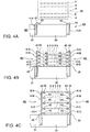
- FIGs. 4A, 4B, and 4C are side views illustrating an example of the operation of the first holding portion 4A and the second holding portion 4B holding and elevating the semiconductor wafers 9.
- an operation of holding and elevating the semiconductor wafers 9 is not limited to this.
- the FOUP 90 is not illustrated for convenience of explanation.
- the plate member conveying robot 2 of the embodiment takes out five semiconductor wafers 9 having different height positions from each other from the FOUP 90 at the same time and widens the pitch of adjacent semiconductor wafers 9. In this state, the semiconductor wafers 9 are conveyed to another spot for process.
- the receiving portions 42 receiving the lowermost semiconductor wafer 9 are provided on the hand 3, and the first holding portion 4A and the second holding portion 4B elevate the remaining four semiconductor wafers 9.
- the movable portion 31 is in a state of being moved away to the rear with respect to the body portion 30 as illustrated in FIG. 2B in a state that the hand 3 is opposed to the FOUP 90 (refer to FIG. 1B ). From this state, the arm supporting shaft 23 lowers, and the arm 20 and the base 21 rotate in the horizontal plane so that the hand 3 advances.
- the hand 3 passes the lower side of the FOUP 90, and the first holding portions 4A are positioned on the front side below the semiconductor wafers 9 in the FOUP 90 and the second holding portions 4B are positioned on the rear side below the semiconductor wafers 9 in the FOUP 90.
- the first holding portions 4A and the second holding portions 4B are in a state that respective receiving portions 42 are uniform at the lowermost level as illustrated in FIG. 3A .
- the arm supporting shaft 23 elevates and also the receiving portions 42 of the first to fourth linearly moving portions 41A, 41B, 41C, 41D elevate by different heights respectively so that the horizontal piece 43 of each receiving portion 42 reaches a height corresponding to the lower surface (slightly lower position) of the corresponding semiconductor wafer 9.
- the arm 20 and the base 21 rotate in the horizontal plane and the hand 3 retreats slightly so that a state that each receiving portion 42 of the first holding portion 4A comes in contact with the peripheral edge portion of the corresponding semiconductor wafer 9 as illustrated in FIG. 4B is achieved. In this state, the second holding portions 4B are positioned in the rear of the semiconductor wafer 9.
- the piston 120 of the actuator 100 is retracted into the housing 110, and the movable portion 31 rotates in the advance direction so that the second holding portions 4B come in contact with the peripheral edge portion of the semiconductor wafer 9.
- the arm supporting shaft 23 elevates slightly, and the first holding portions 4A and the second holding portions 4B vertically move the semiconductor wafers 9 slightly from the FOUP 90.
- the arm 20 and the base 21 rotate in the horizontal plane and the hand 3 retreats so that the semiconductor wafers 9 can be taken out from the FOUP 90.
- the receiving portions 42 of the first to fourth linearly moving portions 41A, 41B, 41C, 41D further elevate by different heights respectively so that a pitch between the adjacent semiconductor wafers 9 can be widen as illustrated in FIG. 4C .
- the arm 20 and the base 21 rotate in the horizontal plane, and a plurality of semiconductor wafers 9 whose pitch is widen are conveyed to another spot for process.
- differences in height between the receiving portions 42 of adjacent linearly moving portions are all equal in a state that the receiving portions 42 of all of the linearly moving portions 41A, 41B, 41C, 41D have finished elevating.
- the pitch changing mechanism 7 for elevating the receiving portions 42 of the respective linearly moving portions 41A, 41B, 41C, 41D by the different heights respectively will be described.
- FIG. 5 is a plan view illustrating the storing space of the body portion 30 of the hand 3, illustrating the pitch changing mechanism 7.
- FIG. 6 is a side view of the pitch changing mechanism 7 in FIG. 5 in a view from the A1 direction, and the base 21 is not illustrated.
- the first holding portion 4A and the second holding portion 4B includes the same pitch changing mechanism 7 respectively, and the pitch changing mechanism 7 of the first holding portion 4A positioned on the left side of the hand 3 in FIG. 1B is illustrated in FIG. 5 for convenience of explanation.
- the pitch changing mechanism 7 is configured by the respective linearly moving portions 41A, 41B, 41C, 41D, a first slider 70 sliding forward and rearward in the body portion 30, and first to fourth link mechanisms 8A, 8B, 8C, 8D which are coupled to the first slider 70 and the respective linearly moving portions 41A, 41B, 41C, 41D and changing a forward and rearward movement of the first slider 70 into a vertical movement and arranged in the storing space in the body portion 30.
- the first to fourth linearly moving portions 41A, 41B, 41C, 41D are positioned outside of the body portion 30, and the first slider 70 and the first to fourth link mechanisms 8A, 8B, 8C, 8D are positioned in the storing space of the body portion 30.
- the semiconductor wafer 9 is positioned above the body portion 30 as illustrated in FIG. 1B , the first slider 70 of the pitch changing mechanism 7 and the first to fourth link mechanisms 8A, 8B, 8C, 8D exist immediately close to the receiving portions 42 for holding the semiconductor wafers 9.
- the "Drive portion" of the present invention is configured by the first slider 70 and the first to fourth link mechanisms 8A, 8B, 8C, 8D.
- the link mechanism positioned innermost of the body portion 30 is referred to as the first link mechanism 8A, and the other link mechanisms are referred to as the second, third, fourth link mechanism 8B, 8C, 8D respectively toward the outside.
- the first to fourth link mechanisms 8A, 8B, 8C, 8D are connected to the corresponding first to fourth linearly moving portions 41A, 41B, 41C, 41D.
- the first link mechanism 8A includes a first link member 80 as a long plate which is provided to one side portion of the first slider 70 and whose proximal end portion is mounted on the first slider 70 turnably, a second link member 81 whose distal end portion is turnably mounted around a connecting shaft 88 positioned in the center portion in the longitudinal direction of the first link member 80 and whose proximal end portion is turnably mounted on the bottom surface of the body portion 30, and a second slider 71 turnably mounted on the distal end portion of the first link member 80 and fixed to the lower end portion of the first linearly moving portion 41.
- the first link member 80 turns about a first axis line L1 which is the center of a mounting spot with the first slider 70 and extends in the left and right direction, and the connecting shaft 88 is centered at a second axis line L2 in parallel with the first axis line L1. Also, a mounting spot of the second link member 81 to the bottom surface of the body portion 30 is centered at a third axis line L3 in parallel with the first axis line L1 and the second axis line L2. The second slider 71 is centered at a fourth axis line L4 in parallel with the first axis line L1 and the second axis line L2.
- the distance between the second axis line L2 and the third axis line L3 is substantially equal to the distance between the first axis line L1 and the second axis line L2 and the distance between the second axis line L2 and the fourth axis line L4. Also, the first axis line L1, the second axis line L2, and the fourth axis line L4 are positioned on substantially the same plane.
- the second slider 71 is fitted in a vertically long hole 34 made in a front wall 33 which is a front end portion of the body portion 30, and therefore the forward and rearward movement is restricted and only the vertical movement is allowed.
- the proximal end portion of a third link member 82 which is a long plate and shorter than the first link member 80 is mounted, and the third link member 82 is turnably provided about the first axis line L1 as the center.
- the connecting shaft 88 is extended in parallel with the first axis line L1 and connected to the third link member 82. As described later, when the first link member 80 and the second link member 81 turn, the third link member 82 turns as well via the connecting shaft 88.
- both the first link member 80 and the second link member 81 are in a substantially horizontal position, and the second slider 71 and the receiving portion 42 of the first linearly moving portion 41A are positioned at the lowermost level.
- the first link member 80 turns about the first axis line L1 as the center so that the second slider 71 faces upward.
- the second link member 81 also turns about the third axis line L3 as the center so that the connecting shaft 88 faces upward.
- a torsion spring 89 shown by short dash lines in FIG. 6 may be provided about the connecting shaft 88 and a leg piece of the torsion spring 89 may be mounted on the first link member 80 and the second link member 81 so that the connecting shaft 88 is biased upward.
- the torsion spring 89 configures the "biasing mechanism for biasing in the direction opposite to the dead point" in the present invention. Also, when the second axis line L2 is positioned above the first axis line L1 and the third axis line L3 in a state that the second slider 71 is positioned in the lowermost level, the possibility that both the link members 80, 81 are pressed against each other when the first slider 70 advances is eliminated.
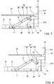
- FIG. 7 is a side view of the pitch changing mechanism 7 in FIG. 5 in a view from the B1 direction, illustrating the second link mechanism 8B.
- the second link mechanism 8B includes the first link member 80, a fourth link member 83 whose one end portion is turnably mounted on the distal end portion of the first link member 80, and a third slider 72 mounted turnably on the other end portion of the fourth link member 83 and fixed to the lower end portion of the second linearly moving portion 41B.
- a mounting spot of the fourth link member 83 and the third slider 72 is centered at a fifth axis line L5 in parallel with the fourth axis line L4 and positioned on substantially the same vertical plane.
- the fourth link member 83 is mounted on a surface of the first link member 80 opposite to the surface on which the second link member 81 is mounted on the first link member 80.
- both the first link member 80 and the fourth link member 83 are in a substantially horizontal position as shown by short dash lines in FIG. 7 , and the third slider 72 and the receiving portion 42 of the second linearly moving portion 41B are positioned at the lowermost level.
- the first link member 80 turns about the first axis line L1 as the center so that the third slider 72 faces upward as mentioned above.
- the fourth link member 83 is inclined so that the other end portion thereof faces downward by the weight of the second linearly moving portion 41B, and the third slider 72 and the receiving portion 42 of the second linearly moving portion 41B reach the uppermost level.
- FIG. 8 is a side view of the pitch changing mechanism 7 in FIG. 5 in a view from the C1 direction, illustrating the third link member 8C.
- the third link member 8C includes the third link member 82, a fifth link member 84 whose one end portion is turnably mounted on the distal end portion of the third link member 82, and a fourth slider 73 mounted turnably on the other end portion of the fifth link member 84 and fixed to the lower end portion of the third linearly moving portion 41C.
- a mounting spot of the fifth link member 84 and the fourth slider 73 is centered at a sixth axis line L6 in parallel with the fourth axis line L4 and positioned on the above-mentioned vertical plane.
- both the third link member 82 and the fifth link member 84 are in a substantially horizontal position as shown by short dash lines in FIG. 8 , and the fourth slider 73 and the receiving portion 42 of the third linearly moving portion 41C are positioned at the lowermost level.
- the third link member 82 turns about the first axis line L1 as the center so that the fourth slider 73 faces upward as mentioned above.
- the fifth link member 84 is inclined so that the other end portion thereof faces downward by the weight of the third linearly moving portion 41C, and the fourth slider 73 and the receiving portion 42 of the third linearly moving portion 41C reach the uppermost level.
- FIG. 9 is a side view of the pitch changing mechanism 7 in FIG. 5 in a view from the D1 direction, illustrating the fourth link mechanism 8D.
- the fourth link mechanism 8D includes the third link member 82, a sixth link member 85 whose one end portion is turnably mounted on the distal end portion of the third link member 82, and a fifth slider 74 mounted turnably on the other end portion of the sixth link member 85 and fixed to the lower end portion of the fourth linearly moving portion 41D.
- a mounting spot of the sixth link member 85 and the fifth slider 74 is centered at a seventh axis line L7 in parallel with the fourth axis line L4 and positioned on the above-mentioned vertical plane.
- the sixth link member 85 is mounted on a surface of the third link member 82 opposite to the surface on which the fifth link member 84 is mounted on the third link member 82.
- both the third link member 82 and the sixth link member 85 are in a substantially horizontal position as shown by short dash lines in FIG. 9 , and the fifth slider 74 and the receiving portion 42 of the fourth linearly moving portion 41D are positioned at the lowermost level.
- the third link member 82 turns about the first axis line L1 as the center so that the fifth slider 74 faces upward as mentioned above.
- the sixth link member 85 is inclined so that the other end portion thereof faces downward by the weight of the fourth linearly moving portion 41D, and the fifth slider 74 and the receiving portion 42 of the fourth linearly moving portion 41D reach the uppermost level.
- the torsion spring 89 may be fitted in the connecting shaft 88 and a leg piece of the torsion spring 89 may be mounted on the third link member 82 and the sixth link member 85 so that the connecting shaft 88 is biased upward.
- the pitch changing mechanism 7 of the first holding portion 4A provided in the body portion 30 is described above, the second holding portion 4B provided to the movable portion 31 also has the pitch changing mechanism 7 having the same configuration as mentioned above. Accordingly, the receiving portions 42 of both the holding portions 4A, 4B for holding the semiconductor wafers 9 are changeable in height by the pitch changing mechanisms 7.
- the four pitch changing mechanisms 7 in total of each of the first holding portion 4A and the second holding portion 4B are driven synchronously. Namely, the first sliders 70 of the four pitch changing mechanisms 7 are driven synchronously. A configuration for driving the four first sliders 70 synchronously will be described later.
- the respective mounting spots of the respective link members 81, 82, 83, 84 and the sliders 71, 72, 73, 74 for driving the first to fourth linearly moving portions 41A, 41B, 41C, 41D to be elevated are centered at the fourth to seventh axis lines L4 to L7 which are all positioned on the same vertical plane. Namely, a plurality of mounting spots are all positioned in the same position in the fourth-back direction.
- first link member 80 and the third link member 82 turn synchronously with each other by the connecting shaft 88 passing through the second axis line L2.
- the sums of a first distance between the first axis line L1 and the second axis line L2 and a second distance between the second axis line L2 and the fourth to seventh axis lines L4 to L7 when the first link member 80 and the third link member 82 are in the horizontal state are the same distance with one another.
- the mounting spot of the second link member 81 and the fourth link member 83 on the first link member 80, and the mounting spot of the fifth link member 84 and the sixth link member 85 on the second link member 82 are all in different positions in the forward and rearward direction. Accordingly, the second distances 2 between the second axis line L2 and the fourth to seventh axis lines L4 to L7 when the first link member 80 and the third link member 82 turn to elevate are different from each other with respect to the respective first to fourth link mechanisms 8A, 8B, 8C, 8D.
- the link mechanisms for elevating the first to fourth linearly moving portions 41A, 41B, 41C, 41D can be suitably realized according to the height positions of the semiconductor wafers 9 to be held by the receiving portions 42 of the respective first to fourth linearly moving portions 41A, 41B, 41C, 41D.
- Component members of the first to fourth link mechanisms 8A, 8B, 8C, 8D are rotated as mentioned above in order to change the pitch of vertically adjacent semiconductor wafers 9, and then the component members of the link mechanisms may be rubbed with each other so as to generate particles as a result. When such particles are adhered to the semiconductor wafer 9, the semiconductor wafer 9 may be deteriorated in quality.
- the particles do not go out of the body portion 30 and the movable portion 31, and therefore there is no possibility that the particles adhere to the semiconductor wafer 9. Further, in order to prevent the particles from going out of the body portion 30 and the movable portion 31, the insides of the storing spaces of the body portion 30 and the movable portion 31 are set to negative pressure.
- the pitch changing mechanism 7 is positioned immediately below the receiving portion 42 of each linearly moving body 40A, 40B, 40C, 40D. Thereby, accuracy of the operation of changing the interval of the receiving portions 42 can be enhanced.
- FIG. 10 is a plan view illustrating a mechanism which synchronizes and drives the four first sliders 70 forward and rearward, showing the body portion 30 and the movable portion 31 configuring the hand 3 by short dash lines.
- a main slide body 5 which is a rigid body extending forward and rearward, is provided so as to move forward and rearward.
- the main slide body 5 has a pair of first drive pieces 50 separated from each other along the left and right direction of the body portion 30 on the front end portion thereof and has a pair of second drive pieces 51 separated from each other along the left and right direction of the body portion 30 on the rear end portion thereof.
- a first slider 70 configuring the pitch changing mechanism of the first holding portion 4A is mounted on the distal end portion of each first drive piece 50.
- Air cylinders 68 are opposed to each other behind the respective second drive pieces 51, and the air cylinder 68 is configured to provide a piston 67 in a housing 69 movably in the forward and rearward direction.
- the distal end portions of the pistons 67 are connected to the second drive pieces 51, and the main slide body 5 is driven forward and rearward by both the air cylinders 68. Note that, although the main slide body 5 is driven by the two air cylinders 68, it may be driven by one air cylinder 68.
- a sub-slide body 52 extending forward and rearward is provided in each movable portion 31 movably forward and rearward, and each sub-slide body 52 is coupled to the second drive piece 51 by a pair of coupling links 53 configured to turn in a horizontal plane.
- a first slider 70 configuring the pitch changing mechanism 7 of the second holding portion 4B is provided to the front end portion of each sub-slide body 52.
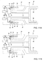
- FIGs. 11A and 11B are plan views illustrating positional relations of the second drive piece 51 and the sub-slide body 52, not illustrating the configuration of the pitch changing mechanism 7 and the second holding portion 4B of the movable portion 31.
- FIG. 11A illustrates the position where the movable portion 31 turns in the advance direction corresponding to FIG. 2A .
- FIG. 11B illustrates the position where the movable portion 31 turns in the retreat direction corresponding to FIG. 2B .
- the first slider 70 driving the second holding portion 4B is provided to the distal end portion of the sub-slide body 52, and the second holding portion 4B is provided to the movable portion 31.
- the sub-slide body 52 when the movable portion 31 turns in the forward and rearward direction, the sub-slide body 52 also moves in the forward and rearward direction.
- Each sub-slide body 52 is coupled to each other by the main slide body 5 and the coupling link 53 so that the sub-slide body 52 can move forward and rearward even in a state that the main slide body 5 is stopped.
- coupling link 53 and the turning auxiliary link plate 63 and the small link plate 60 are in parallel with one another, and these links configure a parallelogram.
- the air cylinder 68 drives the main slide body 5 forward.
- the sub-slide body 52 also advances via the coupling link 53 in the state that the first drive piece 50 and the second drive piece 51 advance and the coupling link 53 does not rotate. Since the main slide body 5 and the sub-slide body 52 move interlockingly, the four first sliders 70 advance synchronously. Thereby, the first to fourth linearly moving portions 41A, 41B, 41C, 41D of the first holding portions 4A and the second holding portions 4B elevate synchronously. Since the four first sliders 70 advance by the same distance, four linearly moving bodies holding a single semiconductor wafer 9 elevate by the same height. Thereby, the semiconductor wafer 9 elevates in a horizontal posture.
- the first to four linearly moving portions 41A, 41B, 41C, 41D of the all pitch changing mechanisms 7 are elevated only by the forward and rearward movement operation of the first sliders 70. Thereby, the mechanism for driving the first to fourth linearly moving portions 41A, 41B, 41C, 41D so as to elevate them becomes simple.
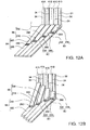
- FIGs. 12A and 12B are perspective views illustrating a first modified example of the pitch changing mechanism 7.
- the first to fourth link mechanisms 8A, 8B, 8C 8D are arranged from the left side to the right side in the figure.
- the first to fourth linearly moving portions 41A, 41B, 41C, 41D are also arranged from the left side to the right side in the figure.
- a configuration of the first to fourth link mechanisms 8A, 8B, 8C, 8D is different from the link mechanism mentioned above.
- the first link mechanism 8A is configured by a first link piece 200 driven forward and rearward in the horizontal posture facing its surface upward and a fifth link piece 240 connected vertically turnably to the distal end portion of the first link piece 200 by a hinge 280.
- the second link mechanism 8B is configured by a second link piece 210 longer than the first link piece 200 and a sixth link piece 250 connected turnably vertically to the distal end portion of the second link piece 210 by the hinge 280 and shorter than the fifth link piece 240.
- the third link mechanism 8C is configured by a third link piece 220 longer than the second link piece 210 and a seventh link piece 260 connected turnably vertically to the distal end portion of the third link piece 220 by the hinge 280 and shorter than the sixth link piece 250.
- the fourth link mechanism 8D is configured by a fourth link piece 230 longer than the third link piece 220 and an eighth link piece 270 connected turnably vertically to the distal end portion of the fourth link piece 230 by the hinge 280 and shorter than the seventh link piece 260.
- the distal end portions of the fifth to eighth link pieces 240, 250, 260, 270 abut on the front wall 33. Thereby, the fifth to eighth link pieces 240, 250, 260, 270 are restricted from advancing.
- the fifth to eighth link pieces 240, 250, 260, 270 are connected with the corresponding first to fourth linearly moving portions 41A, 41B, 41C, 41D through vertically long holes 34 made on the front wall 33 respectively.
- the first to fourth link mechanisms 8A, 8B, 8C, 8D are driven forward and rearward by a common first slider (not illustrated).
- the distal end portions of the fifth to eighth link pieces 240, 250, 260, 270 are abutted on the front wall 33 and restricted from advancing, and therefore, the fifth to eighth link pieces 240, 250, 260, 270 turn so that the distal end portions coupled to the first to fourth linearly moving portions 41A, 41B, 41C, 41D elevate about the hinges 280 as the centers as illustrated in FIG. 12B .
- the receiving portions (not illustrated in FIGs. 12A and 12B ) of the first to fourth linearly moving portions 41A, 41B, 41C, 41D can elevate receiving a peripheral edge portion of the semiconductor wafer 9.
- FIGs. 13A and 13B are side views illustrating a second modified example of the pitch changing mechanism 7.
- the pitch changing mechanism 7 includes the first to fourth link mechanisms connected respectively to the first to fourth linearly moving portions 41A, 41B, 41C, 41D
- the configuration of the link mechanisms are different from the configuration of the link mechanisms mentioned above.
- only the first link mechanism 8A is illustrated.
- the first link mechanism 8A includes a follower slider 300 sliding on the bottom surface of the body portion 30, the first link member 80 whose proximal end portion is mounted turnably on the follower slider 300, the second slider 71 mounted turnably on the distal end portion of the first link member 80 and fixed to the lower end portion of the first linearly moving portion 41, and an elongated rocking member 310 whose one end portion is mounted turnably on the distal end portion of the first link member 80.
- the second slider 71 is fitted in the vertically long hole 34 made in the front wall 33 which is the front end portion of the body portion 30 and allowed to only move vertically similarly to the above-mentioned embodiment.
- the rocking member 310 rocks with an optional point in the longitudinal direction being supported at a fulcrum 320 in the body portion 30, and the other end portion of the rocking member 310 is opposed to an vertically drive actuator 330 arranged in the body portion 30.
- the vertically drive actuator 330 is configured to provide a vertically moving piston 350 vertically movable in a housing 340, and the distal end portion of the vertically moving piston 350 is connected to the other end portion of the rocking member 310.
- the vertically moving piston 350 elevates and the first linearly moving portion 41A is positioned at the lowermost level.
- the rocking member 310 rocks about the fulcrum 320 as the center, and one end portion of the rocking member 310 and the distal end portion of the first link member 80 move upward as illustrated in FIG. 13B .
- the receiving portion 42 of the first linearly moving portion 41A reaches the uppermost level.
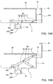
- FIGs. 14A and 14B are side views illustrating a third modified example of the pitch changing mechanism 7. Also in the modified example, the configuration of the first to fourth link mechanisms is different from the configuration of the link mechanisms mentioned above. For convenience of explanation, only the first link mechanism 8A is illustrated.
- the first link mechanism 8A includes the follower slider 300 sliding on the bottom surface of the body portion 30, the elongated first link member 80 whose proximal end portion is mounted turnably on the follower slider 300, the second link member 81 mounted turnably about the connecting shaft 88 whose distal end portion is positioned in the center portion in the longitudinal direction of the first link member 80 and whose proximal end portion is mounted turnably on the bottom surface of the body portion 30, and the second slider 71 mounted turnably on the distal end portion of the first link member 80 and fixed to the lower end portion of the first linearly moving portion 41A.
- a recessed portion 35 is formed on the bottom surface of the body portion 30, and the vertically drive actuator 330 opposed to the lower surface of the proximal end portion of the first link member 80 is arranged in the recessed portion 35.
- the vertically drive actuator 330 is configured to provide the vertically moving piston 350 so as to be movable vertically in the housing 340 as mentioned above, and the distal end portion of the vertically moving piston 350 is connected to the proximal end portion of the first link member 80.
- the first linearly moving portion 41A is positioned at the lowermost level.
- the first link member 80 turn about the mounting portion with the follower slider 300 as the center and also the follower slider 300 advances.
- the distal end portion of the first link member 80 and the distal end portion of the second link member 81 are vertically moved.
- the receiving portion 42 of the first linearly moving portion 41A reaches the uppermost level.
- the lower surface of the peripheral edge portion of the semiconductor wafer 9 is supported by the horizontal piece 43 of the receiving portion 42, as illustrated in FIG. 15A .
- the receiving portion 42 may be formed so that, in the inner surface thereof, a first inclined surface 45 and a second inclined surface 46 whose gradient is more gentle than the first inclined surface 45 are continued and a boundary line SM of both the inclined surfaces 45, 46 supports a peripheral portion of the semiconductor wafer 9.
- the semiconductor wafer 9 slides on the first inclined surface 45 of the receiving portion 42 so as to be placed on the boundary line SM when it is held by the receiving portion 42. Thereby, a horizontal position and a horizontal posture of the semiconductor wafer 9 are corrected and held suitably. Also, since the receiving portion 42 and the semiconductor wafer 9 are in line contact with each other, a contact area between the receiving portion 42 and the semiconductor wafer 9 is small. Thereby, foreign matters adhered to the semiconductor wafer 9 are reduced.
- holding the semiconductor wafer 9 means making the semiconductor wafer 9 in a state that it can be conveyed by the hand 3, and another aspect such as placement or adsorption other than the embodiment mentioned above may by employed.
- the receiving portion 42 can be configured by only the horizontal piece 43 or the horizontal piece 43 and an adsorption pad.
- a semiconductor wafer with a large diameter is being used in phases. Specifically, while a semiconductor wafer with a diameter of about 150mm is used conventionally, a semiconductor wafer with a diameter of about 200mm or 300mm is being used recently, and there is a possibility that a semiconductor wafer with a diameter of about 450mm is used in the future.
- the problem can be avoided by sufficiently enlarging an interval between a plurality of arranged semiconductors wafers.
- a plurality of semiconductor wafers are arranged at an interval as small as possible.
- an interval from the lower surface of a semiconductor wafer to the lower surface of the adjacent semiconductor is 5mm to 10mm, preferably 6mm, for example.
- a plate member such as the substrate holding member in the conventional technique mentioned above does not need to be inserted between a plurality of semiconductor wafers. Accordingly, the problem of interference between a hand and a semiconductor wafer is alleviated.
- the present invention can be applied to a hand gripping a large semiconductor wafer (particularly, a semiconductor wafer with a diameter of 450mm or more). Also, the present invention can be applied to a processing device, a conveying device, or a semiconductor processing device having at least one substrate placing portion including the FOUP 90 or another spot to which a plurality of semiconductor wafers are arranged at an interval of 5mm to 10mm, preferably 6mm.
- first holding portion 4A and the second holding portion 4B are provided two for each of them in the description mentioned above, they may be provided one or more for each of them. However, since a peripheral edge of the semiconductor wafer 9 needs to be supported at three or more points in order to position the semiconductor wafer 9 in the horizontal plane, the first holding portion 4A and the second holding portion 4B need to be provided so as to be supported at three or more points in total.
- the pitch changing mechanism 7 widens a vertical pitch of adjacent semiconductor wafers 9 when conveying a plurality of semiconductor wafers 9 from the FOUP 90 to another spot in the description mentioned above, the vertical pitch may be narrowed.
- the first sliders 70 of the respective pitch changing mechanisms 7 do not necessarily need to be connected to each other physically.
- an actuator such as an air cylinder may be provided individually for each first slider 70 of each pitch changing mechanism 7. In this case, it is desirable that the operation timing of an actuator such as an air cylinder provided individually is synchronized.
- the present invention is useful for an end effector device provided with a pitch changing mechanism which changes a vertical pitch of a plurality of plate members arranged vertically at intervals.
Landscapes
- Engineering & Computer Science (AREA)
- Robotics (AREA)
- Mechanical Engineering (AREA)
- Container, Conveyance, Adherence, Positioning, Of Wafer (AREA)
- Manipulator (AREA)
Claims (6)
- Endeffektorvorrichtung, umfassend:eine Hand (3), die einen Aufnahmeraum aufweist; undeine Vielzahl von Halteabschnitten (4A, 4B), die an der Hand (3) vorgesehen sind und ausgestaltet sind, Teile von jeder einer Vielzahl von Plattenelementen zu halten, um jeweils die Vielzahl von Plattenelementen zu halten, wobei sich die Teile untereinander jeweils in einer Umfangsrichtung eines Umfangskantenabschnitts jedes Plattenelements unterscheiden,wobei jeder der Halteabschnitte (4A, 4B) eine Vielzahl von Aufnahmeabschnitten (42) umfasst, die jeweils Umfangskantenabschnitte der Vielzahl von Plattenelementen aufnehmen, so dass die Vielzahl von Plattenelementen im Wesentlichen parallel zu einer Ebene und in einem Intervall oder in Intervallen zueinander in einer ersten Richtung angeordnet ist, die im Wesentlichen senkrecht zu der einen Ebene ist, und einen Neigungsänderungsmechanismus (7), der so ausgestaltet ist, dass er die Vielzahl von Aufnahmeabschnitten (42) in der ersten Richtung jeweils linear bewegt, um das Intervall oder die Intervalle zu ändern,wobei eine Vielzahl von sich linear bewegenden Abschnitten (41A, 41B), die ausgestaltet sind, sich als Ganzes linear mit der Vielzahl von Aufnahmeabschnitten (42) des Neigungsänderungsmechanismus (7) zu bewegen, so an der Hand (3) vorgesehen ist, dass sie außerhalb der Hand (3) freigelegt ist,wobei eine Vielzahl von Antriebsabschnitten (8A bis 8D), die ausgestaltet sind, jeweils die Vielzahl von sich linear bewegenden Abschnitten (41A, 41B) des Neigungsänderungsmechanismus (7) anzutreiben, in dem Aufnahmeraum der Hand (3) aufbewahrt wird,wobei die Hand (3) einen hohlen Körperabschnitt (30), der so gebildet ist, dass er sich in einer zweiten, im Wesentlichen mit der einen Ebene parallelen Richtung erstreckt, und einen hohlen beweglichen Abschnitt (31) umfasst, der mit einem Proximalendabschnitt des Körperabschnitts verbunden ist, um in der Lage zu sein, sich in der zweiten Richtung nach vorn und nach hinten zu bewegen, undwobei die Vielzahl von Halteabschnitten (4A, 4B) erste Halteabschnitte (4A), die an einem Distalendabschnitt des Körperabschnitts vorgesehen sind, und zweite Halteabschnitte (4B) umfasst, die an dem beweglichen Abschnitt vorgesehen sind.
- Endeffektorvorrichtung nach Anspruch 1, wobei die Endeffektorvorrichtung (1) so ausgestaltet ist, dass die Umfangskantenabschnitte der Vielzahl von Plattenelementen gehalten werden, indem sie von den ersten Halteabschnitten (4A) und den zweiten Halteabschnitten (4B) gegriffen werden, wenn sich der bewegliche Abschnitt nach vorn bewegt, und die Umfangskantenabschnitte der Vielzahl von Plattenelementen aus den zweiten Halteabschnitten (4B) freigegeben werden, wenn sich der bewegliche Abschnitt nach hinten bewegt.
- Endeffektorvorrichtung nach Anspruch 1 oder 2, wobei die ersten Halteabschnitte (4A) und die zweiten Halteabschnitte (4B) jeweils eine Vielzahl von sich linear bewegenden Körpern (40A, 40B) umfassen, die Distalendabschnitte in der ersten Richtung aufweisen, die die Aufnahmeabschnitte bilden, und verbleibende Abschnitte, die die sich linear bewegenden Abschnitte darstellen,
wobei der Antriebsabschnitt, der dem sich linear bewegenden Abschnitt (41A, 41B) entspricht, einen ersten Schieber (70), der ausgestaltet ist, sich linear in der zweiten Richtung zu bewegen, und einen Verbindungsmechanismus (6) umfasst, der ausgestaltet ist, den ersten Schieber (70) und den sich linear bewegenden Körper (40A, 40B) so miteinander zu verbinden, dass eine lineare Bewegung des ersten Schiebers (70) in eine lineare Bewegung in der ersten Richtung geändert wird, und
wobei der Verbindungsmechanismus (6) ausgestaltet ist, den sich linear bewegenden Körper (40A, 40B) nur um die Linearbewegungsentfernung linear zu bewegen, die einer Anordnungs-Reihenfolgenposition in der ersten Richtung des Plattenelements entspricht, die vom Aufnahmeabschnitt aufzunehmen ist. - Endeffektorvorrichtung nach Anspruch 3, wobei der Verbindungsmechanismus (6) Folgendes umfasst:ein erstes Verbindungselement (80), das einen Proximalendabschnitt aufweist, der so mit dem ersten Schieber (70) verbunden ist, dass er um eine erste Achsenlinie, die senkrecht zur ersten Richtung liegt, drehbar ist;ein zweites Verbindungselement (81), das einen Proximalendabschnitt aufweist, der so mit dem ersten Verbindungselement (80) verbunden ist, dass er um eine zweite Achsenlinie, die parallel zur ersten Achsenlinie liegt, drehbar ist; undeinen zweiten Schieber (71), der ausgestaltet ist, in der ersten Richtung entlang einer parallel zur ersten Richtung liegenden Gleitfläche schiebbar zu sein, wobei ein Distalende des zweiten Verbindungselementes (81) so mit dem zweiten Schieber (71) verbunden ist, dass es um eine parallel zur ersten Achsenlinie liegende dritte Achsenlinie drehbar ist, und wobei ein unterer Endabschnitt des sich linear bewegenden Körpers (40A, 40B) mit dem zweiten Schieber (71) verbunden ist,wobei die Vielzahl von Verbindungsmechanismen (6) von jedem der Halteabschnitte (4A, 4B) so ausgestaltet ist, dass in einem Zustand, in dem das erste Verbindungselement (80) senkrecht zur ersten Richtung ist, eine Summe aus einer ersten Entfernung zwischen der ersten Achsenlinie und der zweiten Achsenlinie und einer zweiten Entfernung zwischen der zweiten Achsenlinie und der dritten Achsenlinie eine vorgegebene Entfernung ist, die jeweils in der Vielzahl von Verbindungsmechanismen (6) miteinander identisch ist, und dass aufgrund einer linearen Bewegung des ersten Schiebers (70) in einem Zustand, in dem sich das erste Verbindungselement (80) um die erste Achsenlinie gedreht hat, sich ein Verhältnis der zweiten Entfernung zur vorgegebenen Entfernung in der Vielzahl von Verbindungsmechanismen gemäß der Entfernung der linearen Bewegung untereinander unterscheidet.
- Endeffektorvorrichtung nach Anspruch 4, überdies umfassend: einen Vorspannmechanismus, der ausgestaltet ist, das erste Verbindungselement (80) in eine Richtung gegenüber einem Totpunkt des ersten Verbindungselements (80) und des zweiten Verbindungselements (81) vorzuspannen.
- Endeffektorvorrichtung nach Anspruch 4 oder 5, wobei am Verbindungsmechanismus (6) ein Zylinder (68) vorgesehen ist, der ausgestaltet ist, den ersten Schieber (70), das erste Verbindungselement (80) oder den zweiten Schieber (71) anzutreiben.
Applications Claiming Priority (2)
| Application Number | Priority Date | Filing Date | Title |
|---|---|---|---|
| JP2012285790 | 2012-12-27 | ||
| PCT/JP2013/007582 WO2014103300A1 (ja) | 2012-12-27 | 2013-12-25 | エンドエフェクタ装置 |
Publications (3)
| Publication Number | Publication Date |
|---|---|
| EP2940723A1 EP2940723A1 (de) | 2015-11-04 |
| EP2940723A4 EP2940723A4 (de) | 2016-08-10 |
| EP2940723B1 true EP2940723B1 (de) | 2020-05-20 |
Family
ID=51020416
Family Applications (1)
| Application Number | Title | Priority Date | Filing Date |
|---|---|---|---|
| EP13868539.1A Active EP2940723B1 (de) | 2012-12-27 | 2013-12-25 | Endeffektor |
Country Status (7)
| Country | Link |
|---|---|
| US (1) | US9343344B2 (de) |
| EP (1) | EP2940723B1 (de) |
| JP (1) | JP6314089B2 (de) |
| KR (1) | KR101773272B1 (de) |
| CN (1) | CN104937708B (de) |
| SG (1) | SG11201505000WA (de) |
| WO (1) | WO2014103300A1 (de) |
Families Citing this family (10)
| Publication number | Priority date | Publication date | Assignee | Title |
|---|---|---|---|---|
| JP6309756B2 (ja) * | 2013-12-26 | 2018-04-11 | 川崎重工業株式会社 | エンドエフェクタ装置 |
| JP6314157B2 (ja) * | 2013-12-26 | 2018-04-18 | 川崎重工業株式会社 | エンドエフェクタおよび基板搬送ロボット |
| JP2017175072A (ja) * | 2016-03-25 | 2017-09-28 | 川崎重工業株式会社 | 基板搬送ハンド及びロボット |
| WO2018053149A1 (en) * | 2016-09-15 | 2018-03-22 | Dishcraft Robotics, Inc. | Robotic manipulation using reusable, independent tags |
| CN108695217B (zh) * | 2017-04-07 | 2021-06-29 | 台湾积体电路制造股份有限公司 | 衬底传送装置及其端缘作用器 |
| US20190013215A1 (en) * | 2017-07-05 | 2019-01-10 | Kawasaki Jukogyo Kabushiki Kaisha | Substrate holding hand and substrate conveying apparatus including the same |
| CN109244022B (zh) * | 2018-09-07 | 2023-10-03 | 宁波润华全芯微电子设备有限公司 | 一种机械手末端执行器 |
| TWI746014B (zh) * | 2020-06-16 | 2021-11-11 | 大立鈺科技有限公司 | 晶圓存取總成及其晶圓存取裝置與晶圓載具 |
| CN216120258U (zh) * | 2021-05-07 | 2022-03-22 | 上海大族富创得科技有限公司 | 夹持机构以及具有其的暂存装置和晶圆盒开盒系统 |
| CN119121198A (zh) * | 2024-09-12 | 2024-12-13 | 上海微世半导体有限公司 | 一种立式化学气相沉积炉 |
Family Cites Families (18)
| Publication number | Priority date | Publication date | Assignee | Title |
|---|---|---|---|---|
| JPH0492446A (ja) | 1990-08-07 | 1992-03-25 | Plasma Syst:Kk | 基板搬送ロボット |
| JPH05235147A (ja) | 1992-02-24 | 1993-09-10 | Dainippon Screen Mfg Co Ltd | 基板移載装置 |
| JPH0786371A (ja) * | 1993-09-10 | 1995-03-31 | Dainippon Screen Mfg Co Ltd | 基板搬送装置 |
| JPH1032236A (ja) * | 1996-07-12 | 1998-02-03 | Shinko Electric Co Ltd | ピッチ可変ウェハ移載ハンド |
| JPH11130254A (ja) * | 1997-10-24 | 1999-05-18 | Sharp Corp | 基板搬送カセット |
| JPH11163096A (ja) | 1997-11-21 | 1999-06-18 | Kokusai Electric Co Ltd | 基板移載機のピッチ可変機構 |
| JP2001118909A (ja) | 1999-10-21 | 2001-04-27 | Zenkyo Kasei Kogyo Kk | ピッチ変換装置 |
| JP4278275B2 (ja) | 2000-04-07 | 2009-06-10 | 三菱電機株式会社 | 配列ピッチ変換装置 |
| JP2003309166A (ja) * | 2002-04-15 | 2003-10-31 | Sharp Corp | 半導体ウェハの移載装置 |
| US20040013503A1 (en) * | 2002-07-22 | 2004-01-22 | Jaswant Sandhu | Robotic hand with multi-wafer end effector |
| JP2004158625A (ja) * | 2002-11-06 | 2004-06-03 | Canon Inc | 基板搬送ハンド |
| KR101143138B1 (ko) * | 2004-05-13 | 2012-05-08 | 파나소닉 주식회사 | 부품 공급용 플레이트 수용체 및 부품 공급 장치 |
| JP3998662B2 (ja) | 2004-05-31 | 2007-10-31 | 株式会社東京興業貿易商会 | ウエハピッチ変換機 |
| JP2006176276A (ja) * | 2004-12-22 | 2006-07-06 | Shinko Electric Co Ltd | 昇降装置 |
| JP2006313865A (ja) * | 2005-05-09 | 2006-11-16 | Tatsumo Kk | 基板保持装置 |
| KR101312621B1 (ko) * | 2006-11-29 | 2013-10-07 | 삼성전자주식회사 | 웨이퍼이송장치 |
| JP5823742B2 (ja) * | 2010-07-02 | 2015-11-25 | 芝浦メカトロニクス株式会社 | 把持装置、搬送装置、処理装置、および電子デバイスの製造方法 |
| US9343341B2 (en) * | 2011-08-10 | 2016-05-17 | Kawasaki Jukogyo Kabushiki Kaisha | End effector device and substrate conveying robot including end effector device |
-
2013
- 2013-12-25 WO PCT/JP2013/007582 patent/WO2014103300A1/ja not_active Ceased
- 2013-12-25 JP JP2014554140A patent/JP6314089B2/ja active Active
- 2013-12-25 KR KR1020157018042A patent/KR101773272B1/ko active Active
- 2013-12-25 SG SG11201505000WA patent/SG11201505000WA/en unknown
- 2013-12-25 US US14/758,263 patent/US9343344B2/en active Active
- 2013-12-25 CN CN201380067574.4A patent/CN104937708B/zh active Active
- 2013-12-25 EP EP13868539.1A patent/EP2940723B1/de active Active
Non-Patent Citations (1)
| Title |
|---|
| None * |
Also Published As
| Publication number | Publication date |
|---|---|
| JP6314089B2 (ja) | 2018-04-18 |
| JPWO2014103300A1 (ja) | 2017-01-12 |
| US9343344B2 (en) | 2016-05-17 |
| KR20150096443A (ko) | 2015-08-24 |
| US20150357219A1 (en) | 2015-12-10 |
| KR101773272B1 (ko) | 2017-08-30 |
| WO2014103300A1 (ja) | 2014-07-03 |
| CN104937708A (zh) | 2015-09-23 |
| EP2940723A1 (de) | 2015-11-04 |
| EP2940723A4 (de) | 2016-08-10 |
| CN104937708B (zh) | 2018-04-24 |
| SG11201505000WA (en) | 2015-07-30 |
Similar Documents
| Publication | Publication Date | Title |
|---|---|---|
| EP2940723B1 (de) | Endeffektor | |
| EP3089203A1 (de) | Endeffektor und substratübertragungsroboter | |
| CN103862463B (zh) | 延伸双scara机械手连接装置的伸出距离的方法及设备 | |
| CN101211812B (zh) | 基板处理装置 | |
| JP5506108B2 (ja) | エンドエフェクタを備えたロボット及びその運転方法 | |
| CN101211757B (zh) | 基板处理装置以及基板处理方法 | |
| CN102951445B (zh) | 基板反转装置及基板操作方法以及基板处理装置 | |
| KR20170113314A (ko) | 핸드 유닛 및 이동탑재 방법 | |
| CN101246813A (zh) | 基板处理装置 | |
| CN106104787B (zh) | 末端执行器装置 | |
| CN101801615A (zh) | 基板搬送机械手、真空处理装置 | |
| CN106796906B (zh) | 晶圆搬运方法及装置 | |
| EP3101684B1 (de) | Substratübermittlungssystem und -verfahren | |
| JP2017059777A (ja) | 搬送装置およびはんだボール印刷システム | |
| JP7376285B2 (ja) | 基板処理装置 | |
| Cong et al. | Wafer-handling robots and applications | |
| JPH11214470A (ja) | 基板搬送装置 | |
| CN118213306A (zh) | 衬底传送装置 |
Legal Events
| Date | Code | Title | Description |
|---|---|---|---|
| PUAI | Public reference made under article 153(3) epc to a published international application that has entered the european phase |
Free format text: ORIGINAL CODE: 0009012 |
|
| 17P | Request for examination filed |
Effective date: 20150709 |
|
| AK | Designated contracting states |
Kind code of ref document: A1 Designated state(s): AL AT BE BG CH CY CZ DE DK EE ES FI FR GB GR HR HU IE IS IT LI LT LU LV MC MK MT NL NO PL PT RO RS SE SI SK SM TR |
|
| AX | Request for extension of the european patent |
Extension state: BA ME |
|
| DAX | Request for extension of the european patent (deleted) | ||
| A4 | Supplementary search report drawn up and despatched |
Effective date: 20160712 |
|
| RIC1 | Information provided on ipc code assigned before grant |
Ipc: H01L 21/687 20060101ALI20160706BHEP Ipc: B25J 11/00 20060101ALI20160706BHEP Ipc: H01L 21/677 20060101AFI20160706BHEP |
|
| GRAP | Despatch of communication of intention to grant a patent |
Free format text: ORIGINAL CODE: EPIDOSNIGR1 |
|
| STAA | Information on the status of an ep patent application or granted ep patent |
Free format text: STATUS: GRANT OF PATENT IS INTENDED |
|
| INTG | Intention to grant announced |
Effective date: 20191212 |
|
| GRAS | Grant fee paid |
Free format text: ORIGINAL CODE: EPIDOSNIGR3 |
|
| GRAA | (expected) grant |
Free format text: ORIGINAL CODE: 0009210 |
|
| STAA | Information on the status of an ep patent application or granted ep patent |
Free format text: STATUS: THE PATENT HAS BEEN GRANTED |
|
| AK | Designated contracting states |
Kind code of ref document: B1 Designated state(s): AL AT BE BG CH CY CZ DE DK EE ES FI FR GB GR HR HU IE IS IT LI LT LU LV MC MK MT NL NO PL PT RO RS SE SI SK SM TR |
|
| REG | Reference to a national code |
Ref country code: GB Ref legal event code: FG4D |
|
| REG | Reference to a national code |
Ref country code: CH Ref legal event code: EP |
|
| REG | Reference to a national code |
Ref country code: DE Ref legal event code: R096 Ref document number: 602013069324 Country of ref document: DE |
|
| REG | Reference to a national code |
Ref country code: AT Ref legal event code: REF Ref document number: 1273175 Country of ref document: AT Kind code of ref document: T Effective date: 20200615 |
|
| REG | Reference to a national code |
Ref country code: LT Ref legal event code: MG4D |
|
| REG | Reference to a national code |
Ref country code: NL Ref legal event code: MP Effective date: 20200520 |
|
| PG25 | Lapsed in a contracting state [announced via postgrant information from national office to epo] |
Ref country code: LT Free format text: LAPSE BECAUSE OF FAILURE TO SUBMIT A TRANSLATION OF THE DESCRIPTION OR TO PAY THE FEE WITHIN THE PRESCRIBED TIME-LIMIT Effective date: 20200520 Ref country code: SE Free format text: LAPSE BECAUSE OF FAILURE TO SUBMIT A TRANSLATION OF THE DESCRIPTION OR TO PAY THE FEE WITHIN THE PRESCRIBED TIME-LIMIT Effective date: 20200520 Ref country code: NO Free format text: LAPSE BECAUSE OF FAILURE TO SUBMIT A TRANSLATION OF THE DESCRIPTION OR TO PAY THE FEE WITHIN THE PRESCRIBED TIME-LIMIT Effective date: 20200820 Ref country code: GR Free format text: LAPSE BECAUSE OF FAILURE TO SUBMIT A TRANSLATION OF THE DESCRIPTION OR TO PAY THE FEE WITHIN THE PRESCRIBED TIME-LIMIT Effective date: 20200821 Ref country code: IS Free format text: LAPSE BECAUSE OF FAILURE TO SUBMIT A TRANSLATION OF THE DESCRIPTION OR TO PAY THE FEE WITHIN THE PRESCRIBED TIME-LIMIT Effective date: 20200920 Ref country code: PT Free format text: LAPSE BECAUSE OF FAILURE TO SUBMIT A TRANSLATION OF THE DESCRIPTION OR TO PAY THE FEE WITHIN THE PRESCRIBED TIME-LIMIT Effective date: 20200921 Ref country code: FI Free format text: LAPSE BECAUSE OF FAILURE TO SUBMIT A TRANSLATION OF THE DESCRIPTION OR TO PAY THE FEE WITHIN THE PRESCRIBED TIME-LIMIT Effective date: 20200520 |
|
| PG25 | Lapsed in a contracting state [announced via postgrant information from national office to epo] |
Ref country code: LV Free format text: LAPSE BECAUSE OF FAILURE TO SUBMIT A TRANSLATION OF THE DESCRIPTION OR TO PAY THE FEE WITHIN THE PRESCRIBED TIME-LIMIT Effective date: 20200520 Ref country code: HR Free format text: LAPSE BECAUSE OF FAILURE TO SUBMIT A TRANSLATION OF THE DESCRIPTION OR TO PAY THE FEE WITHIN THE PRESCRIBED TIME-LIMIT Effective date: 20200520 Ref country code: RS Free format text: LAPSE BECAUSE OF FAILURE TO SUBMIT A TRANSLATION OF THE DESCRIPTION OR TO PAY THE FEE WITHIN THE PRESCRIBED TIME-LIMIT Effective date: 20200520 Ref country code: BG Free format text: LAPSE BECAUSE OF FAILURE TO SUBMIT A TRANSLATION OF THE DESCRIPTION OR TO PAY THE FEE WITHIN THE PRESCRIBED TIME-LIMIT Effective date: 20200820 |
|
| REG | Reference to a national code |
Ref country code: AT Ref legal event code: MK05 Ref document number: 1273175 Country of ref document: AT Kind code of ref document: T Effective date: 20200520 |
|
| PG25 | Lapsed in a contracting state [announced via postgrant information from national office to epo] |
Ref country code: AL Free format text: LAPSE BECAUSE OF FAILURE TO SUBMIT A TRANSLATION OF THE DESCRIPTION OR TO PAY THE FEE WITHIN THE PRESCRIBED TIME-LIMIT Effective date: 20200520 Ref country code: NL Free format text: LAPSE BECAUSE OF FAILURE TO SUBMIT A TRANSLATION OF THE DESCRIPTION OR TO PAY THE FEE WITHIN THE PRESCRIBED TIME-LIMIT Effective date: 20200520 |
|
| PG25 | Lapsed in a contracting state [announced via postgrant information from national office to epo] |
Ref country code: RO Free format text: LAPSE BECAUSE OF FAILURE TO SUBMIT A TRANSLATION OF THE DESCRIPTION OR TO PAY THE FEE WITHIN THE PRESCRIBED TIME-LIMIT Effective date: 20200520 Ref country code: CZ Free format text: LAPSE BECAUSE OF FAILURE TO SUBMIT A TRANSLATION OF THE DESCRIPTION OR TO PAY THE FEE WITHIN THE PRESCRIBED TIME-LIMIT Effective date: 20200520 Ref country code: EE Free format text: LAPSE BECAUSE OF FAILURE TO SUBMIT A TRANSLATION OF THE DESCRIPTION OR TO PAY THE FEE WITHIN THE PRESCRIBED TIME-LIMIT Effective date: 20200520 Ref country code: SM Free format text: LAPSE BECAUSE OF FAILURE TO SUBMIT A TRANSLATION OF THE DESCRIPTION OR TO PAY THE FEE WITHIN THE PRESCRIBED TIME-LIMIT Effective date: 20200520 Ref country code: DK Free format text: LAPSE BECAUSE OF FAILURE TO SUBMIT A TRANSLATION OF THE DESCRIPTION OR TO PAY THE FEE WITHIN THE PRESCRIBED TIME-LIMIT Effective date: 20200520 Ref country code: ES Free format text: LAPSE BECAUSE OF FAILURE TO SUBMIT A TRANSLATION OF THE DESCRIPTION OR TO PAY THE FEE WITHIN THE PRESCRIBED TIME-LIMIT Effective date: 20200520 Ref country code: AT Free format text: LAPSE BECAUSE OF FAILURE TO SUBMIT A TRANSLATION OF THE DESCRIPTION OR TO PAY THE FEE WITHIN THE PRESCRIBED TIME-LIMIT Effective date: 20200520 |
|
| REG | Reference to a national code |
Ref country code: DE Ref legal event code: R097 Ref document number: 602013069324 Country of ref document: DE |
|
| PG25 | Lapsed in a contracting state [announced via postgrant information from national office to epo] |
Ref country code: SK Free format text: LAPSE BECAUSE OF FAILURE TO SUBMIT A TRANSLATION OF THE DESCRIPTION OR TO PAY THE FEE WITHIN THE PRESCRIBED TIME-LIMIT Effective date: 20200520 Ref country code: PL Free format text: LAPSE BECAUSE OF FAILURE TO SUBMIT A TRANSLATION OF THE DESCRIPTION OR TO PAY THE FEE WITHIN THE PRESCRIBED TIME-LIMIT Effective date: 20200520 |
|
| PLBE | No opposition filed within time limit |
Free format text: ORIGINAL CODE: 0009261 |
|
| STAA | Information on the status of an ep patent application or granted ep patent |
Free format text: STATUS: NO OPPOSITION FILED WITHIN TIME LIMIT |
|
| 26N | No opposition filed |
Effective date: 20210223 |
|
| PG25 | Lapsed in a contracting state [announced via postgrant information from national office to epo] |
Ref country code: SI Free format text: LAPSE BECAUSE OF FAILURE TO SUBMIT A TRANSLATION OF THE DESCRIPTION OR TO PAY THE FEE WITHIN THE PRESCRIBED TIME-LIMIT Effective date: 20200520 |
|
| REG | Reference to a national code |
Ref country code: DE Ref legal event code: R119 Ref document number: 602013069324 Country of ref document: DE |
|
| REG | Reference to a national code |
Ref country code: CH Ref legal event code: PL |
|
| GBPC | Gb: european patent ceased through non-payment of renewal fee |
Effective date: 20201225 |
|
| PG25 | Lapsed in a contracting state [announced via postgrant information from national office to epo] |
Ref country code: MC Free format text: LAPSE BECAUSE OF FAILURE TO SUBMIT A TRANSLATION OF THE DESCRIPTION OR TO PAY THE FEE WITHIN THE PRESCRIBED TIME-LIMIT Effective date: 20200520 |
|
| REG | Reference to a national code |
Ref country code: BE Ref legal event code: MM Effective date: 20201231 |
|
| PG25 | Lapsed in a contracting state [announced via postgrant information from national office to epo] |
Ref country code: LU Free format text: LAPSE BECAUSE OF NON-PAYMENT OF DUE FEES Effective date: 20201225 Ref country code: FR Free format text: LAPSE BECAUSE OF NON-PAYMENT OF DUE FEES Effective date: 20201231 Ref country code: IE Free format text: LAPSE BECAUSE OF NON-PAYMENT OF DUE FEES Effective date: 20201225 |
|
| PG25 | Lapsed in a contracting state [announced via postgrant information from national office to epo] |
Ref country code: LI Free format text: LAPSE BECAUSE OF NON-PAYMENT OF DUE FEES Effective date: 20201231 Ref country code: DE Free format text: LAPSE BECAUSE OF NON-PAYMENT OF DUE FEES Effective date: 20210701 Ref country code: CH Free format text: LAPSE BECAUSE OF NON-PAYMENT OF DUE FEES Effective date: 20201231 Ref country code: GB Free format text: LAPSE BECAUSE OF NON-PAYMENT OF DUE FEES Effective date: 20201225 |
|
| PG25 | Lapsed in a contracting state [announced via postgrant information from national office to epo] |
Ref country code: IT Free format text: LAPSE BECAUSE OF NON-PAYMENT OF DUE FEES Effective date: 20201225 |
|
| PG25 | Lapsed in a contracting state [announced via postgrant information from national office to epo] |
Ref country code: TR Free format text: LAPSE BECAUSE OF FAILURE TO SUBMIT A TRANSLATION OF THE DESCRIPTION OR TO PAY THE FEE WITHIN THE PRESCRIBED TIME-LIMIT Effective date: 20200520 Ref country code: MT Free format text: LAPSE BECAUSE OF FAILURE TO SUBMIT A TRANSLATION OF THE DESCRIPTION OR TO PAY THE FEE WITHIN THE PRESCRIBED TIME-LIMIT Effective date: 20200520 Ref country code: CY Free format text: LAPSE BECAUSE OF FAILURE TO SUBMIT A TRANSLATION OF THE DESCRIPTION OR TO PAY THE FEE WITHIN THE PRESCRIBED TIME-LIMIT Effective date: 20200520 |
|
| PG25 | Lapsed in a contracting state [announced via postgrant information from national office to epo] |
Ref country code: MK Free format text: LAPSE BECAUSE OF FAILURE TO SUBMIT A TRANSLATION OF THE DESCRIPTION OR TO PAY THE FEE WITHIN THE PRESCRIBED TIME-LIMIT Effective date: 20200520 |
|
| PG25 | Lapsed in a contracting state [announced via postgrant information from national office to epo] |
Ref country code: BE Free format text: LAPSE BECAUSE OF NON-PAYMENT OF DUE FEES Effective date: 20201231 |