EP2940760B1 - Negativelektrodenmaterial für eine sekundärbatterie, leitfähige zusammensetzung für eine sekundärbatterie, negativelektrodenmaterial damit, negativelektrodenstruktur und sekundärbatterie damit sowie verfahren zur herstellung davon - Google Patents
Negativelektrodenmaterial für eine sekundärbatterie, leitfähige zusammensetzung für eine sekundärbatterie, negativelektrodenmaterial damit, negativelektrodenstruktur und sekundärbatterie damit sowie verfahren zur herstellung davon Download PDFInfo
- Publication number
- EP2940760B1 EP2940760B1 EP13868979.9A EP13868979A EP2940760B1 EP 2940760 B1 EP2940760 B1 EP 2940760B1 EP 13868979 A EP13868979 A EP 13868979A EP 2940760 B1 EP2940760 B1 EP 2940760B1
- Authority
- EP
- European Patent Office
- Prior art keywords
- negative electrode
- carbon
- silicon
- solvent
- particle
- Prior art date
- Legal status (The legal status is an assumption and is not a legal conclusion. Google has not performed a legal analysis and makes no representation as to the accuracy of the status listed.)
- Active
Links
Images




Classifications
-
- H—ELECTRICITY
- H01—ELECTRIC ELEMENTS
- H01M—PROCESSES OR MEANS, e.g. BATTERIES, FOR THE DIRECT CONVERSION OF CHEMICAL ENERGY INTO ELECTRICAL ENERGY
- H01M4/00—Electrodes
- H01M4/02—Electrodes composed of, or comprising, active material
- H01M4/04—Processes of manufacture in general
- H01M4/0471—Processes of manufacture in general involving thermal treatment, e.g. firing, sintering, backing particulate active material, thermal decomposition, pyrolysis
-
- H—ELECTRICITY
- H01—ELECTRIC ELEMENTS
- H01M—PROCESSES OR MEANS, e.g. BATTERIES, FOR THE DIRECT CONVERSION OF CHEMICAL ENERGY INTO ELECTRICAL ENERGY
- H01M4/00—Electrodes
- H01M4/02—Electrodes composed of, or comprising, active material
- H01M4/36—Selection of substances as active materials, active masses, active liquids
- H01M4/38—Selection of substances as active materials, active masses, active liquids of elements or alloys
-
- H—ELECTRICITY
- H01—ELECTRIC ELEMENTS
- H01M—PROCESSES OR MEANS, e.g. BATTERIES, FOR THE DIRECT CONVERSION OF CHEMICAL ENERGY INTO ELECTRICAL ENERGY
- H01M10/00—Secondary cells; Manufacture thereof
- H01M10/05—Accumulators with non-aqueous electrolyte
- H01M10/056—Accumulators with non-aqueous electrolyte characterised by the materials used as electrolytes, e.g. mixed inorganic/organic electrolytes
- H01M10/0561—Accumulators with non-aqueous electrolyte characterised by the materials used as electrolytes, e.g. mixed inorganic/organic electrolytes the electrolyte being constituted of inorganic materials only
- H01M10/0562—Solid materials
-
- H—ELECTRICITY
- H01—ELECTRIC ELEMENTS
- H01M—PROCESSES OR MEANS, e.g. BATTERIES, FOR THE DIRECT CONVERSION OF CHEMICAL ENERGY INTO ELECTRICAL ENERGY
- H01M4/00—Electrodes
- H01M4/02—Electrodes composed of, or comprising, active material
- H01M4/04—Processes of manufacture in general
-
- H—ELECTRICITY
- H01—ELECTRIC ELEMENTS
- H01M—PROCESSES OR MEANS, e.g. BATTERIES, FOR THE DIRECT CONVERSION OF CHEMICAL ENERGY INTO ELECTRICAL ENERGY
- H01M4/00—Electrodes
- H01M4/02—Electrodes composed of, or comprising, active material
- H01M4/13—Electrodes for accumulators with non-aqueous electrolyte, e.g. for lithium-accumulators; Processes of manufacture thereof
- H01M4/134—Electrodes based on metals, Si or alloys
-
- H—ELECTRICITY
- H01—ELECTRIC ELEMENTS
- H01M—PROCESSES OR MEANS, e.g. BATTERIES, FOR THE DIRECT CONVERSION OF CHEMICAL ENERGY INTO ELECTRICAL ENERGY
- H01M4/00—Electrodes
- H01M4/02—Electrodes composed of, or comprising, active material
- H01M4/13—Electrodes for accumulators with non-aqueous electrolyte, e.g. for lithium-accumulators; Processes of manufacture thereof
- H01M4/139—Processes of manufacture
-
- H—ELECTRICITY
- H01—ELECTRIC ELEMENTS
- H01M—PROCESSES OR MEANS, e.g. BATTERIES, FOR THE DIRECT CONVERSION OF CHEMICAL ENERGY INTO ELECTRICAL ENERGY
- H01M4/00—Electrodes
- H01M4/02—Electrodes composed of, or comprising, active material
- H01M4/36—Selection of substances as active materials, active masses, active liquids
- H01M4/362—Composites
- H01M4/366—Composites as layered products
-
- H—ELECTRICITY
- H01—ELECTRIC ELEMENTS
- H01M—PROCESSES OR MEANS, e.g. BATTERIES, FOR THE DIRECT CONVERSION OF CHEMICAL ENERGY INTO ELECTRICAL ENERGY
- H01M4/00—Electrodes
- H01M4/02—Electrodes composed of, or comprising, active material
- H01M4/36—Selection of substances as active materials, active masses, active liquids
- H01M4/38—Selection of substances as active materials, active masses, active liquids of elements or alloys
- H01M4/386—Silicon or alloys based on silicon
-
- H—ELECTRICITY
- H01—ELECTRIC ELEMENTS
- H01M—PROCESSES OR MEANS, e.g. BATTERIES, FOR THE DIRECT CONVERSION OF CHEMICAL ENERGY INTO ELECTRICAL ENERGY
- H01M4/00—Electrodes
- H01M4/02—Electrodes composed of, or comprising, active material
- H01M4/36—Selection of substances as active materials, active masses, active liquids
- H01M4/58—Selection of substances as active materials, active masses, active liquids of inorganic compounds other than oxides or hydroxides, e.g. sulfides, selenides, tellurides, halogenides or LiCoFy; of polyanionic structures, e.g. phosphates, silicates or borates
- H01M4/583—Carbonaceous material, e.g. graphite-intercalation compounds or CFx
-
- H—ELECTRICITY
- H01—ELECTRIC ELEMENTS
- H01M—PROCESSES OR MEANS, e.g. BATTERIES, FOR THE DIRECT CONVERSION OF CHEMICAL ENERGY INTO ELECTRICAL ENERGY
- H01M4/00—Electrodes
- H01M4/02—Electrodes composed of, or comprising, active material
- H01M4/62—Selection of inactive substances as ingredients for active masses, e.g. binders, fillers
-
- H—ELECTRICITY
- H01—ELECTRIC ELEMENTS
- H01M—PROCESSES OR MEANS, e.g. BATTERIES, FOR THE DIRECT CONVERSION OF CHEMICAL ENERGY INTO ELECTRICAL ENERGY
- H01M4/00—Electrodes
- H01M4/02—Electrodes composed of, or comprising, active material
- H01M4/62—Selection of inactive substances as ingredients for active masses, e.g. binders, fillers
- H01M4/624—Electric conductive fillers
- H01M4/625—Carbon or graphite
-
- H—ELECTRICITY
- H01—ELECTRIC ELEMENTS
- H01M—PROCESSES OR MEANS, e.g. BATTERIES, FOR THE DIRECT CONVERSION OF CHEMICAL ENERGY INTO ELECTRICAL ENERGY
- H01M10/00—Secondary cells; Manufacture thereof
- H01M10/05—Accumulators with non-aqueous electrolyte
- H01M10/052—Li-accumulators
-
- H—ELECTRICITY
- H01—ELECTRIC ELEMENTS
- H01M—PROCESSES OR MEANS, e.g. BATTERIES, FOR THE DIRECT CONVERSION OF CHEMICAL ENERGY INTO ELECTRICAL ENERGY
- H01M2220/00—Batteries for particular applications
- H01M2220/20—Batteries in motive systems, e.g. vehicle, ship, plane
-
- H—ELECTRICITY
- H01—ELECTRIC ELEMENTS
- H01M—PROCESSES OR MEANS, e.g. BATTERIES, FOR THE DIRECT CONVERSION OF CHEMICAL ENERGY INTO ELECTRICAL ENERGY
- H01M2300/00—Electrolytes
- H01M2300/0017—Non-aqueous electrolytes
- H01M2300/0065—Solid electrolytes
- H01M2300/0068—Solid electrolytes inorganic
- H01M2300/0071—Oxides
-
- Y—GENERAL TAGGING OF NEW TECHNOLOGICAL DEVELOPMENTS; GENERAL TAGGING OF CROSS-SECTIONAL TECHNOLOGIES SPANNING OVER SEVERAL SECTIONS OF THE IPC; TECHNICAL SUBJECTS COVERED BY FORMER USPC CROSS-REFERENCE ART COLLECTIONS [XRACs] AND DIGESTS
- Y02—TECHNOLOGIES OR APPLICATIONS FOR MITIGATION OR ADAPTATION AGAINST CLIMATE CHANGE
- Y02E—REDUCTION OF GREENHOUSE GAS [GHG] EMISSIONS, RELATED TO ENERGY GENERATION, TRANSMISSION OR DISTRIBUTION
- Y02E60/00—Enabling technologies; Technologies with a potential or indirect contribution to GHG emissions mitigation
- Y02E60/10—Energy storage using batteries
-
- Y—GENERAL TAGGING OF NEW TECHNOLOGICAL DEVELOPMENTS; GENERAL TAGGING OF CROSS-SECTIONAL TECHNOLOGIES SPANNING OVER SEVERAL SECTIONS OF THE IPC; TECHNICAL SUBJECTS COVERED BY FORMER USPC CROSS-REFERENCE ART COLLECTIONS [XRACs] AND DIGESTS
- Y02—TECHNOLOGIES OR APPLICATIONS FOR MITIGATION OR ADAPTATION AGAINST CLIMATE CHANGE
- Y02P—CLIMATE CHANGE MITIGATION TECHNOLOGIES IN THE PRODUCTION OR PROCESSING OF GOODS
- Y02P70/00—Climate change mitigation technologies in the production process for final industrial or consumer products
- Y02P70/50—Manufacturing or production processes characterised by the final manufactured product
Definitions
- the present invention relates to a negative electrode active material for a secondary battery, a conductive composition for a secondary battery, a negative electrode material including the same, a negative electrode structure and secondary battery including the same, and a method for manufacturing same, and more specifically, to a negative electrode active material including a silicon particle having an amorphous surface layer, or a silicon-carbon composite, a conductive composition for a secondary battery, which includes carbon, a negative electrode material including the same, a negative electrode structure and secondary battery including the same, and a method for manufacturing the same.
- an information terminal such as a smart phone has rapidly infiltrated into the society due to the ease of exchanging information and sending messages.
- a power storage device such as a capacitor or a secondary battery, which combines a high electric power density and a high energy density, and a long service life.
- a device having the highest energy density is a lithium ion secondary battery using carbon such as graphite in the negative electrode and compounds of lithium and a transition metal in the positive electrode.
- carbon such as graphite in the negative electrode and compounds of lithium and a transition metal in the positive electrode.
- the negative electrode is composed of a carbon material in the "lithium ion battery"
- only up to 1/6 of lithium atoms per carbon atom may be theoretically intercalated. For this reason, it is difficult to achieve a new high capacitance battery, and there is a need for a new material for the negative electrode for achieving high capacity.
- the "lithium ion battery” has high energy density, and thus is expected to be a power source for a hybrid vehicle or an electric vehicle, there is a problem in that the "lithium ion battery” cannot release a sufficient amount of electricity due to high internal resistance of the battery during a rapid discharge, that is, has small output density. For that reason, there is need for the development of a power storage device having high output density and high energy density.
- Tin or silicon may store electrochemically a larger amount of lithium ions, but expands in volume by about 4 times and causes pulverization when expansion and contraction occur due to repeating charge and discharge, thereby causing deterioration in performance of the battery.
- attempts have been conducted for extending the service life of the negative electrode of the battery by grinding silicon or silicon alloys into particulates.
- the silicon material As a method of making the silicon material a particulate, there is a mechanical grinding method, and as a device which may grind the silicon material into a particle size of sub-micron or less, there is a wet beads mill which is a kind of media mill. Grinding by the wet beads mill has problems of (1) reducing the content of oxygen in silicon powder which is a raw material, (2) suppressing oxidation during the grinding, (3) suppressing ground particles from re-aggregating, and (4) suppressing particles from aggregating when the silicon material is ground and then dried.
- Patent Documents 1, 2, 3, 4 and 5 disclose methods of using beads mill in grinding silicon or silicon alloys.
- Patent Document 1 discloses that (i) Si particles having an average particle diameter (D 50 ) of 0.05 to 5 ⁇ m are prepared by a wet grinding using a beads mill, (ii) as a solvent to be used, toluene, xylene, mesitylene, methyl naphthalene, creosote oil and the like which are inert to Si are used, and (iii) a wet-mixing heat treatment is performed by adding ground Si particles and a carbon material or a precursor thereof.
- D 50 average particle diameter
- Patent Document 2 discloses a beads mill as a wet grinding device which forms an alloy from a mixture of Si powder and transition metal by a mechanical alloying method, and grinds the alloy into particles having an average particle diameter (D 50 ) of 0.50 to 20 ⁇ m.
- Patent Document 2 also discloses that it is possible to use a non-protic solvent such as hexane, acetone, and n-butyl acetate, and a protic solvent such as water, methyl alcohol, ethyl alcohol, 1-propyl alcohol, 2-propyl alcohol, 1-butyl alcohol, and 2-butyl alcohol as a dispersion medium used in the wet grinding.
- Patent Document 2 does not disclose a method of grinding the silicon powder into particles having an average particle diameter (Dso) of less than 0.5 ⁇ m.
- Patent Documents 3, 4, and 5 disclose that a Si-Sn-Cu alloy powder is ground into particles having an average particle diameter of up to 0.28 ⁇ m by using a beads mill grinding using zirconia beads as beads and isopropyl alcohol as a medium.
- a beads mill grinding using zirconia beads as beads and isopropyl alcohol as a medium there are problems in that due to pulverization, contact resistance between particles is increased, and charging/discharging efficiency deteriorates, and characteristics expected by using particulates have not been exhibited.
- the present invention has been made in an effort to provide a method for manufacturing a silicon material which may electrochemically store and release a large amount of lithium as a negative electrode active material for a power storage device, which has high energy density.
- the present invention has been made in an effort to provide a method for manufacturing a slurry in which silicon particles for manufacturing a slurry for forming an electrode layer, which suppresses a surface oxidation film of silicon particles from being produced and silicon particles from aggregating, are dispersed in a method for manufacturing an electrode structure for a negative electrode of a power storage device, such as a lithium secondary battery having an active material layer composed of a composite of silicon particles and carbon (a secondary battery using oxidation and reduction reactions of lithium ions).
- the power storage device herein includes a capacitor, a secondary battery, a device which combines a capacitor with a secondary battery, and a device to which a power generation function is also imparted.
- a first exemplary embodiment of the present invention may be a negative electrode active material for a secondary battery, including a silicon particle and an amorphous surface layer formed on the surface of the silicon particle, in which the material is manufactured by manufacturing a slurry including the silicon particle through a dry grinding and a wet grinding, and then mixing and dispersing a material which forms the amorphous surface layer in the slurry.
- a secondary exemplary embodiment of the present invention may be a negative electrode active material for a secondary battery, including a silicon particle, a carbon particle with a graphene structure, and a silicon-carbon composite including fibrous carbon and carbon black, in which the silicon particle is in contact with one or more selected from the group consisting of a carbon particle with a graphene structure, fibrous carbon, and carbon black.
- a third exemplary embodiment of the present invention may be a method for manufacturing a negative electrode active material, the method including: a dry grinding process of performing a dry grinding on a starting material under an inert atmosphere to prepare a dry ground product, and a wet grinding and dispersing process of performing a wet grinding on the dry ground product and dispersing the dry ground product to manufacture a slurry.
- a fourth exemplary embodiment of the present invention may be a conductive composition for a secondary battery, in which carbon is dispersed in a non-protic solvent having no proton donor ability.
- a fifth exemplary embodiment of the present invention may be a method for manufacturing a conductive composition for a secondary battery, the method including: a process of mixing an additive with a non-protic solvent to prepare a solution; and a dispersing process of adding a carbon material to the solution to disperse the material.
- the dispersing process may be performed by a beads mill.
- a sixth exemplary embodiment of the present invention may be a negative electrode material for a secondary battery, including a solvent, a negative electrode active material, the conductive composition of the third exemplary embodiment, and a binder, in which the negative electrode active material includes one or more selected from the group consisting of the negative electrode active material of the first exemplary embodiment and the negative electrode active material of the second exemplary embodiment.
- a seventh exemplary embodiment of the present invention may be a method for manufacturing a negative electrode material for a secondary battery, the method including: preparing a negative electrode active material according to the third exemplary embodiment; preparing a conductive composition according to the fifth exemplary embodiment; and manufacturing a slurry by mixing the negative electrode active material, the conductive composition and a binder with a solvent, in which the negative electrode active material includes one or more selected from the group consisting of the negative electrode active material of claim 1 and the negative electrode active material of claim 7.
- An eighth exemplary embodiment of the present invention may be a negative electrode structure including a conductive metal and a negative electrode material layer formed on the conductive metal, in which the negative electrode material layer includes the negative electrode material of the sixth exemplary embodiment, and the conductive metal may include one or more selected from the group consisting of copper and aluminum.
- a ninth exemplary embodiment of the present invention may be a method for manufacturing a negative electrode structure, the method including: preparing a negative electrode material according to the seventh exemplary embodiment; applying the prepared negative electrode material on a conductive metal; and subjecting the applied negative electrode material to heat treatment.
- a tenth exemplary embodiment of the present invention may be a secondary battery including: the negative electrode structure of the eighth exemplary embodiment; a separator; a positive electrode structure; and a current collector.
- An eleventh exemplary embodiment of the present invention may be a method for manufacturing a secondary battery, the method including: preparing a negative electrode structure according to the ninth exemplary embodiment; and stacking the prepared negative electrode structure, a separator, and a positive electrode structure.
- the negative electrode active material manufactured using a slurry in which a silicon particle is dispersed is formed of a composite of a silicon particle and carbon or a lithium ion solid electrolyte, and silicon particles are suppressed from aggregating due to a low content of oxygen in silicon particles, a power storage device such as a lithium secondary battery may have performances of high energy density, high output density and a longer charging/discharging life cycle by using the negative electrode active material in a negative electrode.
- the method for manufacturing a negative electrode active material according to the present invention is excellent in mass production that the negative electrode active material may be inexpensively manufactured.
- the electronic conductivity of a secondary battery negative electrode may be enhanced by adding the conductive composition according to the present invention during the manufacture of the negative electrode, and accordingly, performance of the battery may be enhanced.
- FIG. 1 is schematic views (a) and (b) of a silicon particle included in a negative electrode active material according to an exemplary embodiment of the present invention, a SEM photograph (c) of the silicon particles, and TEM photographs (d) of the silicon particles.
- FIG. 2 is schematic views of a silicon-carbon composite included in the negative electrode active material according to an exemplary embodiment of the present invention.
- FIG. 3 is a flowchart illustrating a process of manufacturing a negative electrode active material according to an exemplary embodiment of the present invention.
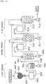
- FIG. 4 is a schematic view illustrating a device system used in a process of manufacturing a negative electrode active material according to an exemplary embodiment of the present invention.
- FIG. 5 is a schematic view of a conductive composition for a secondary battery according to an exemplary embodiment of the present invention.
- FIG. 6 is a cross-sectional view of a negative electrode structure manufactured according to an exemplary embodiment of the present invention.
- FIG. 7 is a flowchart illustrating a process of manufacturing a negative electrode structure manufactured according to an exemplary embodiment of the present invention.
- FIG. 8 is a schematic cross-sectional view of a power storage device manufactured according to an exemplary embodiment of the present invention.
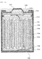
- FIGS. 9 to 11 are schematic views of a coin-type cell, a laminate cell, and a cylinder-type cell, which are examples of a power storage device manufactured according to an exemplary embodiment of the present invention.
- a first exemplary embodiment of the present invention may be a negative electrode active material including a silicon particle 100 and an amorphous surface layer 101 formed on the surface of the silicon particle 100.
- the silicon particle 100 may be a powder obtained by grinding a silicon element bulk material, and the average particle diameter of the silicon particle 100 may be 5 to 200 nm.
- the average particle diameter of the silicon particle 100 is less than 5 nm, the size of the oxidation surface area is increased, so that the performance as a negative electrode active material may be lower than a designed value, and when the average particle diameter thereof is larger than 200 nm, an pulverized surface with respect to a change in volume accompanied by charging/discharging may steadily occur, thereby leading to deterioration in service life characteristics.
- the amorphous surface layer 101 may be formed on the surface of the silicon particle 100, and the amorphous surface layer 101 may include amorphous carbon.
- the surface of the silicon particle 100 may be suppressed from being oxidized.
- the surface layer 101 includes carbon, and thus may be used as a carbon precursor for carbonization or graphitization, which may contribute to electronic conductivity of the negative electrode.
- the electronic conductivity of the negative electrode may be enhanced through carbonization or graphitization of the carbon precursor through firing.
- the thickness of the amorphous surface layer 101 may be 1 to 10 nm. When the thickness of the amorphous surface layer 101 is less than 1 nm, the surface layer 101 is so thin that it is too thin to prevent the silicon particle 100 from being oxidized, and when the thickness is more than 10 nm, lithium ions may be inhibited from being inserted into the active material.
- the primary particle has a long diameter (a) > a small diameter (b) > a thickness (d), the long diameter may be 50 to 300 nm, the small diameter 30 to 200 nm, and the thickness may be 10 to 50 nm.
- FIG. 1 illustrates a scanning electron microscope photograph (c) of silicon particles coated with amorphous carbon and transmission electron microscope photographs (d) thereof.
- FIG. 1(c) is a SEM photograph of silicon particles milled by zirconia beads having a diameter of 0.1 mm.
- the two upper photographs of FIG. 1(d) are TEM photographs of silicon particles milled by zirconia beads having a diameter of 0.2 mm, and the two lower photographs are TEM photographs of silicon particles milled by zirconia beads having a diameter of 0.03 mm. According to the photographs, it can be confirmed that the amorphous carbon layer 101 is formed on the surface of the silicon particle 100.
- the second exemplary embodiment of the present invention is a negative electrode active material including a silicon-carbon composite 110 including one or more selected from the group consisting of a silicon particle 111, a carbon particle 112 with a graphene structure, fibrous carbon 113, and carbon black 114
- the silicon particle 111 may be a negative electrode active material which is in contact with one or more selected from the group consisting of the carbon particle 112 with a graphene structure, the fibrous carbon 113, and the carbon black 114.
- carbon is complexed with the silicon particle 111 which is a main material of the negative electrode active material in various forms. That is, various forms of carbon, that is, the carbon particle 112 with a graphene structure, the fibrous carbon 113, and the bead-like carbon black 114 are complexed with the silicon particle 111. A complex effect may be maximized by complexing various forms of carbon with the silicon particle.
- the silicon particle 100 may be a powder obtained by grinding silicon, and the average particle diameter of the silicon particle 100 may be 5 to 200 nm.
- the amorphous surface layer 101 may be formed on the surface of the silicon particle 100, the amorphous surface layer 101 may include an amorphous carbon layer, and the thickness of the amorphous surface layer 101 may be 1 to 10 nm.
- the description of the silicon particle 100 and the surface layer 101 thereof is the same as that of the first exemplary embodiment.
- the carbon particle 112 with a graphene structure may mean a particle in which a carbon particle has a graphene structure.
- the carbon particle 112 with a graphene structure may include one or more selected from the group consisting of graphene and graphite.
- the average particle diameter of the carbon particle 112 with a graphene structure may be 300 nm to 10 um.
- the average diameter of the fibrous carbon 113 may be 10 to 200 nm.
- the fibrous carbon particle 113 may include one or more selected from the group consisting of carbon nanofiber and carbon nanotube.
- the carbon black 114 has a primary particle having a bead-like connected structure, the average particle diameter of the primary particle may be 10 to 80 nm, and the crystal size of the primary particle may be 2 to 5 nm.
- the average particle diameter of the silicon-carbon composite 110 may be 5 to 20 um.
- the silicon particle 111 may be in contact with one or more selected from the group consisting of the carbon particle 112 with a graphene structure, the fibrous carbon 113 and the carbon black 114. Since carbon such as the carbon particle 112 with a graphene structure, the fibrous carbon 113, and the carbon black 114 are electronically conductive, electronic conductivity between silicon particle and silicon particle may be enhanced due to the presence of one or more of those carbons, which are in contact with the silicon particle 111, thereby enhancing the performance of the battery.
- the silicon-carbon composite 110 may further include a lithium ion solid electrolyte particle in addition to the various carbons, and the silicon particle may be in contact with the lithium ion solid electrolyte particle. In this case, transition of lithium ions may easily occur on the surface of the silicon particle when a power storage device is operated.
- the third exemplary embodiment of the present invention may be a method for manufacturing a negative electrode active material, the method including: a dry grinding process of performing a dry grinding on a starting material under an inert atmosphere to prepare a dry ground product, and a wet grinding and dispersing process of performing a wet grinding on the dry ground product and dispersing the dry ground product to manufacture a slurry.
- a dry grinding process of performing a dry grinding on a starting material under an inert atmosphere to prepare a dry ground product a wet grinding and dispersing process of performing a wet grinding on the dry ground product and dispersing the dry ground product to manufacture a slurry.
- At least one of the dry grinding process and the wet grinding and dispersing process may be performed by a beads mill process. For the coherence of the process, it is preferred that all the processes are performed by the beads mill process.
- a dry grinding may be performed on a starting material under an inert atmosphere to prepare a ground product (a dry grinding process, a first process).
- the starting material is not particularly limited as long as the material may be used as a negative electrode material.
- the starting material may include a silicon powder, and may also include another material in addition to silicon.
- Coal-tar pitch is adopted as an example of the additive, and graphite is adopted as an example of the added material, but the present invention is no limited thereto.
- FIG. 3(a) illustrates the case where the added material graphite is mixed with the starting material silicon.
- FIG. 3(b) illustrates the case where only the silicon powder is used as the starting material, and the added material graphite is added after the dry grinding and before the wet grinding.
- the average particle diameter of the starting material silicon powder may be several mm or less. When the average particle diameter thereof is larger than this value, time needed for the grinding may be prolonged, thereby leading to a drop in productivity.
- the average particle diameter of the silicon particle obtained in the first process is preferably several ⁇ m or less, more preferably in a range of 1 to 10 ⁇ m. In this process, a beads mill is used as the dry grinding device, but other media mills such as a jet mill or a vibrating mill may be used.
- the starting material may be prevented from being oxidized by performing a dry grinding on the starting material under an inert atmosphere. Since heat at high temperature may be generated in the dry grinding process, the particle to be ground may be easily oxidized when the particle is in contact with oxygen in the air, and the dry grinding may be performed under an inert atmosphere to block the starting material to be ground from being in contact with oxygen, thereby preventing the starting material from being oxidized.
- the inert atmosphere may be, but is not limited to, a nitrogen gas atmosphere, or an argon gas atmosphere.
- the surface of the silicon particle When silicon is used as the starting material, the surface of the silicon particle may be prevented from being oxidized. This is because when the surface of the silicon particle is oxidized, the oxidation layer is electrically insulated, and accordingly, electronic conductivity of the negative electrode manufactured by using the oxidation layer deteriorates, and as a result, the performances of the negative electrode and the power storage device may deteriorate.
- the dry ground product may be mixed with a solvent in which the additive is dissolved, and may be ground and dispersed with a wet beads mill to prepare a slurry (a wet grinding and dispersing process, a second process, and a third process).
- a wet grinding and dispersing process a wet grinding and dispersing process, a second process, and a third process.
- the primary particle of the starting material is less than 1 ⁇ m
- the dry grinding process (the first process) may be omitted, and the wet grinding process (the second process) may be initially performed.
- the wet grinding process is performed in two steps of the second process and the third process, but may also be performed in a multi-step process composed of three or more steps.
- the silicon ground in the dry grinding process may be mixed with a solution in which the additive coal-tar pitch is dissolved in a non-protic solvent and be ground for a predetermined time by using a first wet beads mill in the second process, and subsequently, may be further ground by a wet beads mill using beads with a smaller size in the third process, thereby obtaining a slurry in which the silicon particles are dispersed.
- the dry ground starting material needs to be transported to a wet grinding process while not being in contact with oxygen. This is for preventing the surface of the dry ground starting material under an inert atmosphere from being oxidized.
- the surface of silicon may be suppressed from being oxidized during the grinding, and silicon particles may also be suppressed from aggregating. Furthermore, by selecting an additive and an added material which are easily dissolved in the solvent and do not adversely affect the performance of a power storage device even though the additive and the added material remain during the firing, the ground silicon particles may be suppressed from re-aggregating.
- a solvent having no proton donor ability a non-protic solvent
- a solvent having proton donor ability a protic solvent
- non-protic solvent examples include one or more selected from the group consisting of a cyclic hydrocarbon, an aromatic compound, a ketone-based solvent, an ether-based solvent, an amide-based solvent, and a nitrile-based solvent, and among them, a cyclic hydrocarbon, an aromatic compound, and a ketone-based solvent are most preferred.
- the most preferred specific examples of the non-protic solvent include N-methyl-2-pyrrolidone, ⁇ -butyrolactone, N,N-dimethylacetamide, 1,3-dimethyl-2-imidazolidine, and cyclohexane.
- the additive is not particularly limited as long as the additive is a material which is soluble or easily dispersed in a medium used in the wet grinding and cracking, and is easily carbonized during the firing process under an inert atmosphere.
- the additive coal-tar pitch is added before the second process, but may be added before the first process, before the third process, or before the fourth process.
- coal-tar pitch petroleum pitch or a polycyclic aromatic hydrocarbon may also be used. Coal-tar pitch and petroleum pitch are inexpensive, and thus are most preferred.
- polycyclic aromatic hydrocarbon corresponds to naphthalene, anthracene, phenanthrene, naphthacene, pyrene, triphenylene, chrysene, pentacene, benzopyrene, corannulene, coronene, ovalene, and the like.
- the amount of additive added is preferably in a range of 0.05 to 5 parts by weight, more preferably in a range of 0.2 to 3 parts by weight, and most preferably in a range of 0.5 to 2 parts by weight, based on 100 parts by weight of silicon.
- the additive has an effect that the additive is dissolved in a non-protic solvent to generate a newly ground surface of silicon, and simultaneously the surface is covered with the solution to suppress the aggregation through electrostatic repulsion or hydrophobic repulsion.
- the protic solvent When the protic solvent is used as a solvent of the wet beads mill, there is an advantage in that problems such as environmental contamination are minimal.
- water and alcohol are preferred, and as the additive used in this case, it is preferred to use a polyvinyl pyrrolidone having a ketone or ether structure, or one or more polymers of a carboxymethylcellulose sodium salt and a group of polyvinyl alcohols.
- the amount of additive added is preferably in a range of 0.05 to 5 parts by weight, more preferably in a range of 0.1 to 3 parts by weight, and most preferably in a range of 0.5 to 2 parts by weight, based on 100 parts by weight of the solvent.
- silicon When silicon is ground in the solvent in which the additive is dissolved, silicon may be more easily bonded to adjacent atoms due to the unsaturated bond (dangling bond) of the silicon atom, which is formed on the surface of the ground silicon particle, and accordingly, (1) it is possible to prevent ground silicon particles from re-aggregating and uniformly disperse ground silicon particles, (2) it is possible to suppress an oxidation film from being formed on the surface of silicon particle, and (3) it is possible to enhance the dispersion of silicon particles in the silicon particle-carbon composite, and form the interface of silicon with a carbon material well. Further, the simultaneously ground added material may also maintain a more stable dispersion state than the solvent in which the additive is dissolved. Accordingly, in the third process, it is possible to obtain silicon and a slurry which is more uniformly dispersed than the added material.
- the particle diameter of the silicon particle introduced into the wet beads mill in the second process is preferably several ⁇ m or less, more preferably in a range of 1 to 10 ⁇ m.
- the wet grinding process may be performed until the average particle diameter of the starting material becomes 3 nm to 200 nm.
- the average particle diameter of the silicon particle obtained in the third process is preferably in a range of 3 to 200 nm, more preferably in a range of 10 to 200 nm, and most preferably in a range of 20 to 100 nm.
- the average particle diameter of the starting material is less than 5 nm, aggregation among the molecules of the starting material may occur, and accordingly, dispersion may not be achieved well in the subsequent dispersion process, and when the diameter thereof is more than 200 nm, the particles of the starting material are too large to achieve dispersity sufficient to be used as a negative electrode active material.
- the wet beads mill used in the present invention is preferably a beads mill which enables continuous grinding provided with a circulation tank.
- a material for the beads used in the beads mill is preferably zirconia, alumina, silicon nitride, and titania.
- zirconia or alumina has high grinding capacity due to high hardness, and thus is preferred because zirconia or alumina remains only in a small amount even while being used in the manufacture of an electrode or a battery in the subsequent process, and thus has almost no adverse effect, and the diameter thereof is p9referably 2 mm or less, and more preferably in a range of 0.03 to 0.8 mm in the wet beads mill.
- the added material may be a material which is not dissolved in a medium used in the wet grinding. When subjected to the dispersing process, the added material is branched, and thus may be present while being uniformly dispersed in the slurry.
- the added material may include one or more selected from the group consisting of graphite, graphene, carbon nanotube, carbon fiber, amorphous carbon, and a lithium ion inorganic solid electrolyte.
- the added material may be graphite, graphene, carbon nanofiber, carbon nanotube, and an inorganic solid electrolyte of lithium ions.
- the inorganic solid electrolyte of lithium ions is more preferably a so-called "ceramic electrolyte" such as metal, oxide, carbide, a boron compound, a sulfide, and a phosphoric acid compound
- an added material for example, graphite
- a slurry of an added material which is finely ground and dispersed in advance in a separate process, may also be added to the second process to the fourth process.
- the added material has a surface potential different from that of silicon, and thus may suppress silicon particles from aggregating.
- particles of the added material may be present while being more uniformly dispersed among silicon particles by adding the added material (graphite) during the grinding of the silicon particles, and when an electrode structure is formed using the same, it is possible to complement electronic conduction among silicon particles, or conduction of lithium ions into silicon particles.
- ground silicon particles may be suppressed from re-aggregating and an insulating oxidation film may be suppressed from being formed on the surface of silicon particle, and when a negative electrode is manufactured, conductivity may be maintained due to reduction in the oxidation film present among silicon particles, and electronic conductivity among silicon particles, that is, electronic conductivity of the negative electrode may be enhanced through carbonization or graphitization of a carbon source through an additional firing process, and as a result, performance of the battery may be enhanced. Further, when silicon is ground in a solvent including a solid electrolyte, lithium ions may be easily inserted into the surface of silicon particle when a power storage device is operated.
- a process of irradiating ultrasonic waves to perform the treatment may also be included in the first to third processes.
- the ultrasonic treatment has an effect that particles are facilitated to be dispersed in the solvent, and the aggregating particles are re-dispersed.
- amorphous carbon may also be produced on the surface of silicon particle by irradiating ultrasonic wave energy on the slurry in which silicon particles are dispersed in a solution of coal-tar pitch, petroleum pitch, and a polycyclic aromatic compound, and carbon-covered silicon particles may be formed.
- a slurry having an appropriate viscosity may be obtained by adjusting the amount of solvent by a method such as desolvation by pressurization and centrifuge during the fourth process.
- a firing (calcination) process of obtaining a negative electrode active material by drying and calcining the slurry may be further included, and from this, it is possible to obtain a silicon particle having a surface layer of the amorphous carbon according to the first exemplary embodiment, or a negative electrode active material of the silicon particle-carbon composite according to the second exemplary embodiment (a calcination process).
- the calcination process may be performed under reduced pressure or under an inert atmosphere.
- the inert atmosphere may be a nitrogen gas atmosphere or an argon gas atmosphere.
- the calcination When the calcination is performed under an inert atmosphere, oxidation may be prevented, thereby contributing to the enhancement of electronic conductivity of the negative electrode.
- the calcination may be performed at a temperature at which all the organic materials in the slurry may be volatilized and removed.
- the fourth exemplary embodiment of the present invention may be a conductive composition for a secondary battery, in which carbons 121 to 123 are dispersed in a non-protic solvent 124 having no proton donor ability.
- the conductive composition for a secondary battery according to the present exemplary embodiment may be used as a conductive auxiliary agent which may complement electronic conductivity of the negative electrode.
- the conductive auxiliary agent is present on the surface of particle of the negative electrode active material, and thus connects the negative electrode active material to the negative electrode active material, and accordingly, electronic conductivity among the negative active materials is increased by the conductive auxiliary agent, and as a result, the conductive auxiliary agent may contribute to enhancing performance of the negative electrode.
- the description is made with reference to the negative electrode, but is not limited to the negative electrode, and may also be applied to the positive electrode in some cases.
- the non-protic solvent may include one or more selected from the group consisting of a hydrocarbon, an aromatic compound, a ketone-based solvent, an ether-based solvent, an ester-based solvent, an amide-based solvent, and a nitrile-based solvent.
- the non-protic solvent means a solvent having no proton donor ability, and when a non-protic solvent is used, a material to be ground or dispersed may be more efficiently suppressed from being oxidized.
- One or more additives selected from the group consisting of coal-tar pitch and a polycyclic aromatic compound may be added to the non-protic solvent.
- the additive is not particularly limited as long as the additive is a material which may be easily carbonized under an inert atmosphere.
- the additive may be carbonized, and thus may also contribute to enhancing electronic conductivity of the negative electrode.
- Carbon may be added in order to enhance electronic conductivity of the negative electrode.
- the additive need not be limited to carbon, and is not particularly limited as long as the additive is a material which is excellent in electronic conductivity.
- the carbon may include one or more selected from the group consisting of fibrous carbon 121, a carbon particle 122 with a graphene structure, and carbon black 123.
- the carbon may be present in various forms, and thus is not limited to the listed materials, and may also include other forms of carbon.
- the fibrous carbon 121 has an average diameter of 10 to 200 nm
- the particle 122 with a graphene structure has an average particle diameter of 10 to 200 nm
- the carbon black 123 has an average particle diameter of 10 to 80 nm
- the content of carbon may be 0.05 to 1 g/L.
- contribution to electronic conductivity is so low that an effect of enhancing the electronic conductivity of the negative electrode is minimal, and when the content thereof is more than 1.0 g/L, the content of carbon is so high that the fraction of the negative electrode active material in the entire negative electrode is low, and accordingly, the function as a negative electrode active material may deteriorate.
- the protic solvent may include one or more selected from the group consisting of water and alcohol, and one or more additives selected from the group consisting of polyvinyl pyrrolidone, a carboxymethylcellulose sodium salt, and sodium cholate may be added to the protic solvent.
- the fifth exemplary embodiment of the present invention may be a method for manufacturing a conductive composition for a secondary battery, the method including: a process of mixing an additive with a non-protic solvent to prepare a solution; and a dispersing process of adding carbon to the solution to disperse the material.
- the dispersing process may be performed by a beads mill.
- the non-protic solvent may include one or more selected from the group consisting of a hydrocarbon, an aromatic compound, a ketone-based solvent, an ether-based solvent, an ester-based solvent, an amide-based solvent, and a nitrile-based solvent, and one or more additives selected from the group consisting of coal-tar pitch and a polycyclic aromatic compound may be added to the non-protic solvent.
- the carbon may include one or more selected from the group consisting of fibrous carbon, a carbon particle with a graphene structure, and carbon black, the fibrous carbon has an average particle of 10 to 200 nm, the particle with a graphene structure has an average particle diameter of 10 to 200 nm, and the carbon black has an average particle diameter of 10 to 80 nm, has a structure in which a plurality of primary particles is connected in a bead-like shape, and may have a crystal particle size of 2 to 5 nm.
- the content of carbon may be 0.05 to 1.0 g/L.
- a protic solvent may be used instead of the non-protic solvent, and in this case, the protic solvent may include one or more selected from the group consisting of water and alcohol, and one or more additives selected from the group consisting of polyvinyl pyrrolidone, a carboxymethylcellulose sodium salt, and sodium cholate may be added to the protic solvent.
- the description of the solvent, the additive, the carbon, the dispersing process and the like is the same as that of the dry grinding process and the wet grinding and dispersing process in the third exemplary embodiment.
- the present exemplary embodiment is different from the third exemplary embodiment in that the present exemplary embodiment is not subjected to calcination process.
- the sixth exemplary embodiment of the present invention may be a negative electrode material including a negative electrode active material, a conductive agent, a binder, and a solvent.
- the negative electrode material may be a slurry in which the negative electrode active material, the conductive agent, the binder, and the solvent are dispersed by a ball mill.
- the negative electrode active material may include one or more of the negative electrode active material in the first exemplary embodiment, and the negative electrode active material in the second exemplary embodiment.
- the conductive agent may include the conductive composition in the fourth exemplary embodiment.
- PVDF polyvinylidene fluoride
- NMP N-methyl-2-pyrrolidone
- SBR styrene-butadiene rubber
- CMC carboxymethyl cellulose
- a seventh exemplary embodiment of the present invention may be a method for manufacturing a negative electrode material for a second battery, the method including: preparing a negative electrode active material; preparing a conductive agent; and manufacturing a slurry by mixing the negative electrode active material, the conductive agent and a binder with a solvent.
- a negative electrode active material in a slurry state may be prepared according to the third exemplary embodiment.
- the negative electrode active material may be the negative electrode active material in the first exemplary embodiment, or may include the negative electrode active material in the second exemplary embodiment.
- the description of the solvent, the additive, the carbon, the dispersing process and the like is the same as that of the dry grinding process and the wet grinding and dispersing process in the third exemplary embodiment.
- the present exemplary embodiment is different from the third exemplary embodiment in that the present exemplary embodiment is not subjected to calcination process.
- a conductive agent (a conductive composition) may be prepared according to the fifth exemplary embodiment.
- a negative electrode material in a slurry state may be prepared by mixing a negative electrode active material in a slurry state with a conductive agent and a binder, and then uniformly dispersing the conductive agent and the binder through a method such as milling.
- the binder it is possible to use polyvinylidene fluoride (PVDF) dissolved in N-methyl-2-pyrrolidone (NMP), styrene-butadiene rubber (SBR) dissolved in water, or carboxymethyl cellulose (CMC).
- PVDF polyvinylidene fluoride
- NMP N-methyl-2-pyrrolidone
- SBR styrene-butadiene rubber
- CMC carboxymethyl cellulose
- an eighth exemplary embodiment of the present invention may be a negative electrode structure 305 including a conductive metal (a current collector) 300 and a negative electrode material layer 304 formed on the conductive metal 300.
- the negative electrode material layer 304 may include the negative electrode material in the sixth exemplary embodiment.
- the negative electrode structure 305 may be formed by applying a negative electrode material on the current collector 300, and then drying the negative electrode material to remove the solvent.
- the negative electrode material layer 304 may be in a state where the negative electrode active material 304 is bonded to the conductive agent 303 by the binder 302.
- the current collector 300 is not particularly limited as long as the current collector 300 is a metal which has electronic conductivity, and is chemically stable to the electrolytic solution and the like, and copper, aluminum and the like may be specifically used.
- the ninth exemplary embodiment of the present invention may be a method for manufacturing a negative electrode structure, the method including: preparing a negative electrode material according to the seventh exemplary embodiment (first to fourth processes); applying the prepared negative electrode material on the conductive metal; and subjecting the applied negative electrode material to heat treatment (fifth process).
- a negative electrode material (a slurry for an electrode coating) may be prepared according to the seventh exemplary embodiment (first to fourth processes). That is, a negative electrode material (a slurry for an electrode coating) in a slurry state may be prepared (a fourth process) by preparing a negative electrode active material in a slurry state according to the third exemplary embodiment (first to third processes, here, the description of the solvent, the additive, the carbon, the dispersing process and the like is the same as that of the dry grinding process and the wet grinding and dispersing process in the third exemplary embodiment.
- the present exemplary embodiment is different from the third exemplary embodiment in that the present exemplary embodiment is not subjected to calcination process), preparing the conductive agent (a conductive composition) according to the fifth exemplary embodiment, mixing a conductive agent and a binder with the negative electrode active material in the slurry state, and uniformly dispersing the conductive agent and the binder by a method such as a beads mill.
- a slurry for forming an electrode layer may be manufactured by at least adding a binder or adding a conductive auxiliary agent or a solvent of a binder to a slurry of the silicon particles obtained in the third process.
- the binder to be added in the fourth process is preferably a polymer selected from polyamic acid, polyimide, polyamideimide, and an epoxy resin when the solvent of the slurry is a non-protic solvent.
- the solvent of the slurry is a protic solvent, it is preferred to use one or more polymers selected from a carboxymethylcellulose sodium salt, polyvinyl alcohol, and chitosan, and it is more preferred to cause the cross-linking reaction to induce crosslinking between polymers.
- a conductive auxiliary agent and a solvent for adjusting the viscosity may be added to a slurry for forming an electrode, and as the conductive auxiliary agent, it is possible to use one or more selected from the group consisting of graphite, graphene, carbon nanotube, carbon nanofiber, and amorphous carbon.
- the description of the negative electrode active material, the conductive agent, the solvent, the binder and the like is the same as that of the previous exemplary embodiment.
- a negative electrode structure may be manufactured by applying a negative electrode material (a slurry for an electrode coating) on a current collector at a predetermined thickness using a doctor blade method, drying the current collector to which the negative electrode material is applied, and performing heat treatment thereon.
- the drying temperature is preferably in a range of 80 to 120° in the atmosphere.
- An organic material such as a binder may be volatilized and removed while being subjected to heat treatment process.
- the heat treatment temperature is determined by the boiling point of the binder and the solvent.
- the heat treatment at 120°C or more needs to be performed under vacuum (reduced pressure), or under inert gas atmosphere.
- the binder When polyamic acid or polyamideimide of a precursor of polyimide is used as the binder, and N-methyl-2-pyrrolidone is used as the solvent, a temperature range of 180 to 350°C is preferred, and the atmosphere is preferably an atmosphere under reduced pressure or an inert atmosphere.
- argon, nitrogen, or helium is preferred, but argon is more preferred.
- a tenth exemplary embodiment of the present invention may be a power storage device including the negative electrode structure 402 of the eighth exemplary embodiment, a separator 403, a positive electrode structure 405, and current collectors 401 and 404.
- Representative examples of the power storage device include a lithium secondary battery, and here, there are types such as a coin-type, a laminate-type and a cylinder-type.
- FIG. 9 to 11 illustrate a cross-sectional views of coin-type, laminate-type, and cylinder-type lithium secondary batteries, respectively.
- the separator, the positive electrode structure, and the current collector those generally used may be adopted.
- the eleventh exemplary embodiment of the present invention may be a method for manufacturing a power storage device (a secondary battery), the method including: preparing a negative electrode structure according to the ninth exemplary embodiment; and stacking the prepared negative electrode structure, a separator, and the positive electrode structure.
- the present exemplary embodiment describes a stack-type structure, but the present invention is not limited thereto, and may be applied to the winding-type, the coin-type and the like.
- the description of the separator, the positive electrode structure, the current collector and the like is the same as that of the previous exemplary embodiments.
- a silicon-carbon composite was manufactured according to the flowchart of FIG. 3 and the grinding system of FIG. 4 .
- a mixed powder in which 95 parts by weight of a silicon power and 5 parts by weight of a graphite powder were mixed, was used.
- a silicon powder having a purity of 99% and an average particle diameter of 500 ⁇ m was used as the silicon powder, and a graphite powder having an average particle diameter of 20 ⁇ m was used as the graphite powder.
- a quantitative feeder 201 was used to introduce the starting material into a dry beads mill 202, and the starting material was ground into an average diameter of 3 ⁇ m.
- a dry grinding was performed under nitrogen gas atmosphere by using zirconia beads having a particle diameter of 5 mm.
- a solid-liquid mixture tank 204 was used to mix the powder obtained from the dry grinding with a cyclohexane solution in which 0.02 wt% of coal-tar pitch was dissolved, and a mixed solution was obtained by adding 0.05 wt% of an artificial graphite having an average particle diameter of 5 ⁇ m, 0.0025 wt% of a multilayer carbon nanotube having a diameter of 150 ⁇ m, and 0.2 wt% of Li 2 O-Al 2 O 3 -SiO 2 -P 2 O 5 -TiO 2 which is a lithium ion conductor (a lithium ion inorganic solid electrolyte) having an average particle diameter of 5 ⁇ m.
- a pump 205 was used to supply the mixed solution to a first wet beads mill 209 filled with zirconia beads having a particle diameter of 0.5 mm via a first circulation tank 207, and a slurry was obtained by grinding an average slurry of the starting material for 1 hour while circulating the average slurry.
- the slurry was stored in a second circulation tank 210, supplied to a second wet beads mill 212 filled with zirconia beads having a particle diameter of 0.03 mm, and ground.
- the slurry was ground for 2 hours while being circulated until the average particle diameter of the starting material became 400 nm, and the obtained slurry was stored in a ground product dispersion slurry tank 213.
- cyclohexane was added to the slurry obtained by allowing the resulting mixture to pass through a third circulation tank (not illustrated), supplying the mixture to a wet beads mill filled with zirconia beads having a particle diameter of 0.1 mm, and grinding the slurry for 2.5 hours while circulating the slurry, so as to adjust the concentration of silicon to 5 wt%, the slurry was ground for 2 hours while being circulated by allowing the slurry to pass through the circulation tank and supplying the slurry to a wet beads mill filled with zirconia beads having a particle diameter of 0.05 mm, and then a slurry, in which silicon particles, carbon particles, and ion conductor particles were dispersed, was obtained.
- the ground dispersed slurry was dried in a vacuum dryer to remove cyclohexane and obtain a mixture of silicon-lithium ion inorganic solid electrolyte-graphite-coal-tar pitch.
- the mixture was subjected to heat treatment under the condition of 800°C under an argon gas atmosphere in a firing furnace, thereby manufacturing a silicon-lithium ion inorganic solid electrolyte-carbon composite.
- N-methyl-2-pyrrolidone as a dispersion medium was introduced into a first circulation tank 207 and dispersed therein such that a metal silicon powder having a purity of 99% and a particle diameter of 300 ⁇ m or less as the starting raw material has a concentration of 20 wt%, and zirconia beads having a size of 0.5 mm as a first wet beads mill 209 were used to grind the resulting mixture for 1.5 hours while circulating the resulting mixture under a nitrogen gas atmosphere until the average particle diameter of the silicon particles became 400 nm.
- the obtained slurry was allowed to pass through a second circulation tank 210 and was supplied to a second wet beads mill 212 filled with zirconia beads having a particle diameter of 0.3 mm to grind the slurry for 2.5 hours while circulating the slurry by a peristaltic pump 211.
- N-methyl-2-pyrrolidone was added to the obtained slurry, the resulting mixture was allowed to pass through a third circulation tank filled with zirconia beads having a particle diameter of 0.1 mm and was supplied to a third wet beads mill filled with zirconia beads having a particle diameter of 0.1 mm, and the slurry was ground for 2.5 hours while being circulated by adding coal-tar pitch thereto so as to have a concentration of 0.1 wt% with respect to silicon, thereby obtaining a slurry of silicon particles having an average particle diameter of 180 nm.
- the obtained slurry was dried to obtain an average particle diameter of 50 to 200 nm observed by scanning electron microscopy. As the scanning electron microscope, JSM-7400F manufactured by Jeol Ltd., was used.
- N-methyl-2-pyrrolidone was added to the slurry obtained in Example M2 to adjust the concentration of silicon to 5 wt%, and then the slurry was allowed to pass through a circulation tank and supplied to a wet beads mill filled with zirconia beads having a particle diameter of 0.05 mm, so as to grind the slurry for up to 3 hours while circulating the slurry, but the slurry was not ground until an average particle diameter of 110 nm or less 1 hour after the grinding began to be performed.
- coal-tar pitch was added in an amount of 0.04 wt% based on the weight of silicon and the resulting mixture was further ground for 1 hour, and as a result, a slurry having an average particle diameter of which the silicon particles was reduced to 65 nm could be obtained.
- the obtained slurry was dried, and the particle diameters observed by scanning electron microscopy were 30 to 100 nm, and particles having a minimum of 5 nm were also observed by - transmission electron microscopy.
- a silicon-carbon composite was obtained under the same conditions as in Example M2, except that ethyl alcohol in which 0.1 wt% of polyvinyl pyrrolidone was dissolved was used as the solvent instead of an N-methyl-2-pyrrolidone solution in which 0.1 wt% of coal-tar pitch was dissolved.
- Example M2 a silicon slurry was obtained by grinding the slurry to a median diameter of 400 nm for 1.5 hours while circulating the slurry under nitrogen atmosphere using zirconia beads having a size of 0.5 mm in the first wet beads mill 209.
- Example M1 coal-tar pitch was not added to cyclohexane.
- a silicon-carbon composite was obtained in the same manner as in Example M1, except for the above matter.
- a wet grinding process in which a metal silicon having an average particle diameter of 20 ⁇ m was used as a starting material and ethanol was used as a medium, was performed instead of performing the dry grinding process in Example M1. Subsequently, a dry silicon powder was manufactured by performing a dispersing process, performing the desolvation, and then grinding the slurry.
- a silicon-carbon composite was manufactured by dispersing the dry silicon powder in a cyclohexane solution in which 2 wt% of coal-tar pitch was dissolved, drying the dispersion under reduced pressure, and then performing heat treatment at 800°C under an argon gas atmosphere.
- the size, distribution state, and oxygen content of the silicon (Si) particles were analyzed and evaluated by using scanning electron microscopy (SEM), transmission electron microscopy (TEM), energy dispersive spectrometer (EDS) related to the transmission electron microscopy, and electron energy loss spectrometer (EELS), and the results are shown below.
- SEM scanning electron microscopy
- TEM transmission electron microscopy
- EDS energy dispersive spectrometer
- EELS electron energy loss spectrometer
- the aggregation size of the silicon particles was Comparative Example M1 > Reference Example M1 > Reference Example M2 > Example M2 > Example M1 in this order.
- the particle size of the silicon particles was Comparative Example M1 > Reference Example M2 > Reference Example M1 > Example M2 > Example M1 in this order.
- silicon may be further pulverized, silicon particles are uniformly dispersed in the internal structure of the obtained silicon-carbon composite, and the oxygen content is also small.
- An artificial graphite having an average particle diameter of 5 ⁇ m according to Example M1, Example M2, Reference Example M1, Reference Example M2, and Comparative Example M1, a multilayer carbon nanotube having a diameter of 150 nm, and polyamic acid were added and mixed so as to have 26 parts by weight of silicon, 49 parts by weight of the artificial graphite, 12 parts by weight of carbon nanotube, and 12 parts by weight of the polyamic acid solid content, the mixture was kneaded, and then a slurry for forming an electrode layer was manufactured.
- the slurry was applied on a copper foil having a thickness of 17 ⁇ m using an applicator, and dried at 110°C for 0.5 hour, the thickness and the density was adjusted by a roll press, and a negative electrode active material layer having a thickness of 20 to 40 ⁇ m and a density of 0.9 to 1.2 g/cm 3 was formed on a copper foil current collector to manufacture a negative electrode structure.
- the negative electrode structures manufactured of the silicon-carbon composites of Example M1, Example M2, Reference Example M1, Reference M2, and Comparative Example M1 were referred to as the negative electrode structures of Example EM1, Example EM2, Reference Example EM1, Reference Example EM2, and Comparative Example EM1, respectively.
- the negative electrode structure was used as a single electrode to evaluate the amount of electrochemical lithium inserted as follows.
- a coin-type cell in which each of the negative electrode structures of Example EM1, Example EM2, Reference Example EM1, Reference Example EM2, and Comparative Example EM1 was pressed to a predetermined size and used as a working electrode, and the metal lithium was used as a counter electrode, was manufactured, and the amount of the inserted electrochemical lithium of each negative electrode structure was evaluated.
- the lithium electrode was manufactured by compressing a metal lithium foil having a thickness of 140 ⁇ m on a nickel foil expanded metal, and pressing the compressed product to a predetermined size.
- a coin-type evaluation cell was manufactured as follows (see FIG. 9 ). That is, the negative electrode structure was inserted into a positive electrode can 507 under a dry atmosphere with a dew point of -50°C or less, polyethylene films having a porosity of 40% with a microporous structure at a thickness of 17 ⁇ m as a separator were disposed to overlap each other, and a polypropylene gasket 508 was formed. Subsequently, an electrolytic solution was added dropwise to the separator to form an ion conductor (a separator) 503.
- lithium negative electrodes 502 and 501 were overlapped with each other, and the lid was covered with a negative electrode cap 506 and caulked by a caulking device, thereby manufacturing an evaluation cell.
- a solution which was obtained by dissolving 1 M (mol/l) of lithium phosphate hexafluoride (LiPF 6 ) in a solvent in which ethylene carbonate from which moisture was sufficiently removed and diethyl carbonate were mixed at a volume ratio of 3:7, was used.
- the amount of electrochemical lithium inserted was evaluated as follows. The evaluation was performed by using the lithium electrode as a negative electrode and each working electrode as a positive electrode, discharging the battery until the cell voltage became 0.01 V, and charging the battery until the cell voltage became 1.50 V. That is, the amount of electricity discharged was defined as the amount of electricity used to insert lithium, and the amount of electricity charged was defined as the amount of electricity used to release lithium.
- discharging-charging was performed once at an electric current of 0.05 C and 50 times at an electric current of 0.5 C, evaluations were performed on the amount of Li inserted (amount of electricity) once, the amount of Li released (amount of electricity) once, the ratio (%) of the amount of Li released to the amount of Li inserted once, the amount of Li released (amount of electricity) at the tenth time to the amount once, the amount of Li released (amount of electricity) at the fiftieth time to the tenth time, and Li insertion and desorption (or release) of a negative electrode composed of various active materials, and the results are shown below.
- Example EM1 Reference Example EM1 > Example EM2 > Reference Example EM2 > Comparative Example EM1 in this order.
- Example EM1 The largest values for the amount of Li released at the tenth time to the first time and the amount of Li released at the fiftieth time to the tenth time were Example EM1 > Example EM2 > Reference EM1 > Reference Example EM2 > Comparative Example EM1 in this order.
- the negative electrode structure according to the present invention has good performance.
- Table 1 shows the comparison of current characteristics of the amount of Li desorbed (capacity) in Example EM2 and Reference Example EM1. However, for the amount of Li desorbed at each current value, the capacity at a current value of 0.05 C was standardized at 1.0.
- an electrode (Example EM2), which was manufactured by using a silicon particle having an average particle diameter of up to 180 nm obtained by adding coal-tar pitch and grinding the silicon particles, had good current rate characteristics of the amount of lithium desorbed, and had a larger amount of lithium desorbed at a higher current.
- FIGS. 8 to 10 illustrate a coin-type cell, a laminate or pouch cell, and a cylinder-type cell as an example of the lithium secondary battery.
- Each of the negative electrode structures of Example EM2, Reference Example EM1, Reference Example EM2, and Comparative Example EM1 was pressed to a predetermined size and used in the negative electrode, thereby manufacturing each coin-type cell. All the coin-type cells were assembled under a dry atmosphere with a dew point of -50°C or less.
- a positive electrode previously manufactured was inserted in a positive electrode can 507, polyethylene films having a porosity of 40% with a microporous structure at a thickness of 17 ⁇ m as a separator were disposed to overlap each other, a polypropylene gasket 508 was set, an electrolytic solution was added dropwise to the separator to form an ion conductor (separator) 503, and then negative electrodes 502 and 501 were overlapped with each other, and the lid was covered with a negative electrode cap 506 and was caulked in advance by a caulking device, thereby manufacturing a coin cell.
- Each of the coin cells which were manufactured by using, as a negative electrode, each negative electrode structure of Example EM2, Reference Example EM1, Reference Example EM2, and Comparative Example EM1 formed by using each silicon-carbon composite of Example M1, Example M2, Reference Example M1, Reference Example M2, and Comparative Example M1 as a material for a negative electrode active material, was used as each power storage device for Example DM2, Reference Example DM1, Reference Example DM2, and Comparative Example DM1.
- the electrolytic solution a solution, which was obtained by dissolving 1 M (mol/l) of lithium phosphate hexafluoride (LiPF 6 ) in a solvent in which ethylene carbonate from which moisture was sufficiently removed and diethyl carbonate were mixed at a volume ratio of 3:7, was used.
- LiPF 6 lithium phosphate hexafluoride
- a positive electrode structure used as a positive electrode of the power storage device of the present invention was manufactured as follows.
- a slurry for forming a positive electrode active material layer was manufactured by mixing 100 parts by weight of lithium nickel cobalt manganese oxide (LiNi 1/3 Co 1/3 Mn 1/3 O 2 ) with 4 parts by weight of acetylene black, adding 50 parts by weight of an N-methyl-2-pyrrolidone solution containing 10 wt% of polyvinylidene fluoride and 50 parts by weight of N-methyl-2-pyrrolidone thereto, and dispersing the mixture by a wet beads mill.
- lithium nickel cobalt manganese oxide LiNi 1/3 Co 1/3 Mn 1/3 O 2
- the slurry was applied on an aluminum foil having a thickness of 14 ⁇ m using a coater, dried at 110°C for 1 hour, and then dried at 150°C under further reduced pressure.
- the thickness was adjusted by a roll press machine to manufacture a positive electrode structure in which a positive electrode active material layer having a thickness of 82 ⁇ m and a density of 3.2 g/cm 3 was formed on an aluminum foil current collector.
- the positive electrode structure was pressed to a predetermined size, thereby manufacturing a LiNi 1/3 Co 1/3 Mn 1/3 O 2 positive electrode structure.
- the charging and discharging in which the battery was charged at a constant voltage of 4.2 V and rested for 10 minutes, and then was discharged until the cell voltage became 2.7 V at a constant current density of 0.2 C and stopped for 10 minutes, was repeated three times, and then charging and discharging characteristics were evaluated by repeating charging and discharging 100 times at a current density of 1 C, and the results are shown below.
- Example DM1 > Example DM2 > Reference Example DM1 > Reference Example DM2 >> Comparative Example DM1 in this order.
- the negative electrode according to the present invention has good performance.
Landscapes
- Chemical & Material Sciences (AREA)
- Chemical Kinetics & Catalysis (AREA)
- Electrochemistry (AREA)
- General Chemical & Material Sciences (AREA)
- Composite Materials (AREA)
- Engineering & Computer Science (AREA)
- Manufacturing & Machinery (AREA)
- Inorganic Chemistry (AREA)
- Materials Engineering (AREA)
- Physics & Mathematics (AREA)
- General Physics & Mathematics (AREA)
- Condensed Matter Physics & Semiconductors (AREA)
- Battery Electrode And Active Subsutance (AREA)
- Silicon Compounds (AREA)
- Electric Double-Layer Capacitors Or The Like (AREA)
- Cell Electrode Carriers And Collectors (AREA)
- Secondary Cells (AREA)
Claims (13)
- Negatives Elektrodenaktivmaterial für eine Sekundärbatterie, umfassend:ein Siliziumkarbid-Komposit, umfassend ein Siliziumpartikel, einen Kohlenstoff und ein Lithium-Ionen-Festelektrolytpartikel, wobei der Kohlenstoff und der Lithium-Ionen-Festelektrolytpartikel in Kontakt mit dem Siliziumpartikel stehen,wobei der Kohlenstoff eines oder mehrere ausgewählt aus der Gruppe bestehend aus einem Kohlenstoffpartikel mit einer Graphenstruktur, faserigem Kohlenstoff und Industrieruß umfasst,wobei der Kohlenstoffpartikel mit einer Graphenstruktur einen durchschnittlichen Partikeldurchmesser von 300 nm bis 10 µm aufweist, der faserige Kohlenstoff einen durchschnittlichen Durchmesser von 10 bis 200 nm aufweist, der Industrieruß ein Primärpartikel mit einer kugelartig verbundenen Struktur aufweist, der Primärpartikel einen durchschnittlichen Partikeldurchmesser von 10 bis 80 nm aufweist und der Primärpartikel eine Kristallgröße von 2 bis 5 nm aufweist, undwobei das Siliziumpartikel einen durchschnittlichen Partikeldurchmesser von 5 bis 200 nm aufweist, und eine amorphe Oberflächenschicht auf einer Oberfläche des Siliziumpartikels ist, der eine Dicke von 1 bis 10 nm aufweist, und wobei die amorphe Oberflächenschicht amorphen Kohlenstoff aufweist.
- Negatives Elektrodenaktivmaterial für eine Sekundärbatterie nach Anspruch 1, wobei das Siliziumkarbid-Komposit einen durchschnittlichen Partikeldurchmesser von 5 bis 20 µm aufweist.
- Negatives Elektrodenaktivmaterial für eine Sekundärbatterie nach Anspruch 1, wobei
das Kohlenstoffpartikel mit einer Graphenstruktur eines oder mehrere aus der Gruppe bestehend aus Graphen und Graphit umfasst, und wobei der faserige Kohlenstoff eines oder mehrere aus der Gruppe bestehend aus Kohlenstoffnanofasern und Kohlenstoffnanoröhren umfasst. - Negatives Elektrodenaktivmaterial für eine Sekundärbatterie nach Anspruch 1, wobei das Siliziumpartikel ein Primärpartikel mit einem langen Durchmesser > ein kleiner Durchmesser > eine Dicke aufweist, wobei der lange Durchmesser 50 bis 300 nm beträgt, der kleine Durchmesser 30 bis 200 nm beträgt und die Dicke 10 bis 50 nm beträgt.
- Negatives Elektrodenaktivmaterial für eine Sekundärbatterie nach Anspruch 1,
wobei der Lithium-Ionen-Festelektrolyt eines oder mehrere aus der Gruppe bestehend aus einem schwefelbasiertem amorphen Elektrolyt, einem schwefelhaltigen Glas, Lithiumnitrid (Li3N), einem Material mit einer NASICON-Struktur, einem Material mit einer Granatstruktur und einer Germanium-Phosphor-Schwefel-Verbindung umfasst, und
wobei der schwefelbasierte amorphe Elektrolyt Li2S-P2O5 umfasst, das Material mit einer NASICON-Struktur Li1+x+yAlxTi2-xSiyP3-yO12 (x=0,3, y=0,2) umfasst, das Material mit einer Granatstruktur Li7La3Zr2O12 umfasst und die Germanium-Phosphor-Schwefel-Verbindung Li10GeP2S12 umfasst. - Verfahren zur Herstellung eines negativen Elektrodenaktivmaterials, wobei das Verfahren Folgendes umfasst:einen Trockenmahlprozess zum Durchführen eines Trockenmahlens auf einem Ausgangsmaterial unter einer inerten Atmosphäre, um ein Trockenmahlprodukt herzustellen, bei dem verhindert wird, dass eine Oberfläche oxidiert; undeinen Nassmahl- und Dispergierprozess, wobei das Trockenmahlprodukt, ein hinzugefügtes Material, und ein Additiv in eine Lösung gegeben werden, und dann ein Nassmahlen auf das Gemisch angewandt wird und das Gemisch dispergiert wird, um einen Schlamm herzustellen,wobei mindestens einer des Trockenmahlprozesses und des Nassmahl- und Dispergierprozesses durch einen Rührwerkskugelprozess durchgeführt wird,wobei als Ausgangsmaterial Silizium verwendet wird,wobei der Nassmahlprozess so durchgeführt wird, dass das Ausgangsmaterial einen durchschnittlichen Partikeldurchmesser von 5 nm bis 200 nm aufweist, undwobei als das hinzugefügte Material ein Lithium-Ionen-Festelektrolyt verwendet wird, und eines oder mehrere ausgewählt aus der Gruppe bestehend aus Graphit, Graphen, Kohlenstoffnanorohr, Kohlenstofffaser und amorphen Kohlenstoff.
- Verfahren nach Anspruch 6, wobei eines oder mehrere ausgewählt aus der Gruppe bestehend aus Kohlenteerpech und einer polyzyklischen aromatischen Verbindung als das Additiv verwendet werden.
- Verfahren nach Anspruch 6, wobei eines oder mehrere ausgewählt aus der Gruppe bestehend aus einem schwefelbasiertem amorphen Elektrolyt, einem schwefelhaltigen Glas, Lithiumnitrid (Li3N), einem Material mit einer NASICON-Struktur, einem Material mit einer Granatstruktur und einer Germanium-Phosphor-Schwefel-Verbindung als der Lithium-Ionen-Festelektrolyt verwendet werden und wobei Li2S-P2O5 als der schwefelbasierte amorphe Elektrolyt verwendet wird, Li1+x+yAlxTi2-xSiyP3-yO12 (x=0,3, y=0,2) als das Material mit einer NASICON-Struktur verwendet wird, Li7La3Zr2O12 als das Material mit einer Granatstruktur verwendet wird und Li10GeP2S12 als die Germanium-Phosphor-Schwefel-Verbindung verwendet wird.
- Verfahren nach Anspruch 6, wobei
ein nicht protisches Lösungsmittel, das keine Protonendonorfähigkeit aufweist, als das Lösungsmittel verwendet wird,
eines oder mehrere ausgewählt aus der Gruppe bestehend aus einem zyklischen Kohlenwasserstoff, einer aromatischen Verbindung, einem ketonbasierten Lösungsmittel, einem ätherbasierten Lösungsmittel, einem esterbasierten Lösungsmittel, einem amidbasierten Lösungsmittel und einem nitrilbasierten Lösungsmittel als das nicht protische Lösungsmittel verwendet werden, und/oder
ein protisches Lösungsmittel, das eine Protonendonorfähigkeit aufweist, als das Lösungsmittel verwendet wird, und
eines oder mehrere ausgewählt aus der Gruppe bestehend aus Alkohol und Wasser als das protische Lösungsmittel verwendet werden. - Verfahren nach Anspruch 6, ferner umfassend: einen Kalzinierprozess, wobei ein negatives Elektrodenaktivmaterial durch Kalzinieren des hergestellten Schlamms nach dem Nassmahl- und Dispergierprozess erhalten wird,
wobei der Kalzinierungsprozess unter reduziertem Druck oder unter einer inerten Atmosphäre durchgeführt wird. - Negatives Elektrodenmaterial für eine Sekundärbatterie, umfassend ein Gemisch aus dem negativen Elektrodenaktivmaterial nach Anspruch 1, einem Bindemittel und einer leitenden Verbindung für eine Sekundärbatterie in einem Lösungsmittel,
wobei die leitende Verbindung einen weiteren Kohlenstoff umfasst, der in einem
nicht protischen Lösungsmittel ohne Protonendonorfähigkeit oder in einem protischen Lösungsmittel mit Protonendonorfähigkeit dispergiert ist. - Negatives Elektrodenmaterial nach Anspruch 11, wobei das nicht protische Lösungsmittel eines oder mehrere ausgewählt aus der Gruppe bestehend aus einem Wasserstoffkohlenstoff, einer aromatischen Verbindung, einem ketonbasierten Lösungsmittel, einem ätherbasierten Lösungsmittel, einem esterbasierten Lösungsmittel, einem amidbasierten Lösungsmittel und einem nitrilbasierten Lösungsmittel umfasst,
wobei die leitende Verbindung ferner ein oder mehrere Additive ausgewählt aus
der Gruppe bestehend aus Kohlenteerpech und einer polyzyklischen aromatischen Verbindung umfasst,
wobei der weitere Kohlenstoff eines oder mehrere aus der Gruppe bestehend aus faserigen Kohlenstoff, einem Kohlenstoffpartikel mit einer Graphenstruktur und Industrieruß umfasst, und
wobei das protische Lösungsmittel eines oder mehrere ausgewählt aus der Gruppe bestehend aus Wasser und Alkohol umfasst. - Negatives Elektrodenmaterial nach Anspruch 12, wobei der weitere Kohlenstoff in einem Gehalt von 0,05 bis 1,0g/l enthalten ist.
Applications Claiming Priority (2)
| Application Number | Priority Date | Filing Date | Title |
|---|---|---|---|
| KR1020120155529A KR101939270B1 (ko) | 2012-12-27 | 2012-12-27 | 이차전지용 음극활물질, 이차전지용 도전성 조성물, 이를 포함하는 음극재료, 이를 포함하는 음극구조체 및 이차전지, 및 이들의 제조방법 |
| PCT/KR2013/012349 WO2014104842A1 (ko) | 2012-12-27 | 2013-12-27 | 이차전지용 음극활물질, 이차전지용 도전성 조성물, 이를 포함하는 음극재료, 이를 포함하는 음극구조체 및 이차전지, 및 이들의 제조방법 |
Publications (3)
| Publication Number | Publication Date |
|---|---|
| EP2940760A1 EP2940760A1 (de) | 2015-11-04 |
| EP2940760A4 EP2940760A4 (de) | 2016-07-20 |
| EP2940760B1 true EP2940760B1 (de) | 2018-02-21 |
Family
ID=51021776
Family Applications (1)
| Application Number | Title | Priority Date | Filing Date |
|---|---|---|---|
| EP13868979.9A Active EP2940760B1 (de) | 2012-12-27 | 2013-12-27 | Negativelektrodenmaterial für eine sekundärbatterie, leitfähige zusammensetzung für eine sekundärbatterie, negativelektrodenmaterial damit, negativelektrodenstruktur und sekundärbatterie damit sowie verfahren zur herstellung davon |
Country Status (6)
| Country | Link |
|---|---|
| US (3) | US9761869B2 (de) |
| EP (1) | EP2940760B1 (de) |
| JP (1) | JP2016509739A (de) |
| KR (1) | KR101939270B1 (de) |
| CN (1) | CN104781958B (de) |
| WO (1) | WO2014104842A1 (de) |
Families Citing this family (56)
| Publication number | Priority date | Publication date | Assignee | Title |
|---|---|---|---|---|
| JP2016066418A (ja) * | 2014-09-22 | 2016-04-28 | 新日鐵住金株式会社 | 電極活物質材料、電極、電池、及び、電極活物質材料の製造方法 |
| US9966629B2 (en) | 2015-02-03 | 2018-05-08 | Samsung Electronics Co., Ltd. | Sodium-conducting solid electrolyte |
| WO2016194787A1 (ja) * | 2015-06-02 | 2016-12-08 | 富士フイルム株式会社 | 負極用材料、全固体二次電池用電極シートおよび全固体二次電池ならびに全固体二次電池用電極シートおよび全固体二次電池の製造方法 |
| KR102314042B1 (ko) * | 2015-06-09 | 2021-10-19 | 삼성전자주식회사 | 음극 활물질 복합체, 상기 음극 활물질 복합체를 포함하는 음극, 상기 음극을 포함하는 리튬 이차전지, 및 상기 음극 활물질 복합체의 제조방법 |
| KR101977931B1 (ko) | 2015-12-10 | 2019-05-13 | 주식회사 엘지화학 | 리튬 이차전지용 음극활물질의 제조 방법 및 이를 적용한 리튬 이차전지 |
| JP6857464B2 (ja) * | 2016-08-19 | 2021-04-14 | 小林 光 | 複合樹脂材料、複合樹脂材料の製造装置、及び複合樹脂材料の製造方法、並びに複合樹脂材料用添加剤 |
| US11081690B2 (en) | 2016-09-12 | 2021-08-03 | Imerys Graphite & Carbon Switzerland Ltd. | Compositions and uses thereof |
| DE102016221782A1 (de) | 2016-11-07 | 2018-05-09 | Wacker Chemie Ag | Kohlenstoff-beschichtete Siliciumpartikel für Lithiumionen-Batterien |
| US11158847B2 (en) | 2016-12-23 | 2021-10-26 | Lg Chem, Ltd. | Negative electrode active material and negative electrode including the same |
| JPWO2018193994A1 (ja) * | 2017-04-18 | 2020-05-14 | トヨタ自動車株式会社 | 全固体リチウムイオン二次電池 |
| JP6969175B2 (ja) * | 2017-06-20 | 2021-11-24 | 株式会社豊田中央研究所 | リチウム二次電池用負極材料、その製造方法、及びそれを備えるリチウム二次電池 |
| WO2019016925A1 (en) * | 2017-07-20 | 2019-01-24 | Nec Corporation | CARBON CONDUCTIVE ADDITIVES FOR LITHIUM ION BATTERY |
| JP6760224B2 (ja) * | 2017-07-20 | 2020-09-23 | トヨタ自動車株式会社 | 全固体電池用負極活物質 |
| JP7041804B2 (ja) | 2017-09-13 | 2022-03-25 | エルジー エナジー ソリューション リミテッド | 固体電解質を含む全固体電池用の電極 |
| KR102245126B1 (ko) * | 2017-11-09 | 2021-04-28 | 주식회사 엘지화학 | 음극 활물질, 상기 음극 활물질을 포함하는 음극, 및 상기 음극을 포함하는 이차 전지 |
| KR102164709B1 (ko) * | 2017-11-20 | 2020-10-12 | 한국생산기술연구원 | 음극 집전체층, 이를 포함하는 음극 복합체 및 이를 포함하는 플렉서블 이차전지 적층체 |
| JP6927110B2 (ja) * | 2018-03-26 | 2021-08-25 | トヨタ自動車株式会社 | 負極合剤の製造方法 |
| KR20190114151A (ko) * | 2018-03-29 | 2019-10-10 | 현대자동차주식회사 | 리튬 이차전지 및 그 제조방법 |
| CN111937192A (zh) | 2018-04-05 | 2020-11-13 | 株式会社半导体能源研究所 | 负极活性物质、二次电池及电子设备 |
| KR102211835B1 (ko) | 2018-04-05 | 2021-02-02 | 삼성에스디아이 주식회사 | 리튬 이차 전지용 음극 활물질 및 이를 포함하는 리튬 이차 전지 |
| JP7030970B2 (ja) * | 2018-07-25 | 2022-03-07 | ワッカー ケミー アクチエンゲゼルシャフト | シリコン粒子の熱処理 |
| CN110858642B (zh) * | 2018-08-24 | 2021-12-28 | 荣盛盟固利新能源科技股份有限公司 | 一种硅/石墨/固态电解质复合负极材料的制备方法 |
| CN109148863B (zh) * | 2018-09-03 | 2021-11-19 | 新奥石墨烯技术有限公司 | 钛酸锂-石墨烯复合材料及其制备方法和应用 |
| CN112753113B (zh) * | 2018-09-26 | 2024-05-10 | 松下知识产权经营株式会社 | 非水电解质二次电池用负极以及非水电解质二次电池 |
| WO2020067480A1 (ja) * | 2018-09-28 | 2020-04-02 | 日本製鉄株式会社 | 複合粒子群、負極活物質粒子群、負極、電池、及び、複合粒子群に含有される凸部露出複合粒子 |
| CN109411707A (zh) * | 2018-10-30 | 2019-03-01 | 郭和俊 | 一种磷酸铁锂电芯的制备方法 |
| KR102893748B1 (ko) | 2019-01-30 | 2025-12-01 | 에스케이온 주식회사 | 이차전지 및 이의 제조방법 |
| JP7261995B2 (ja) | 2019-01-30 | 2023-04-21 | パナソニックIpマネジメント株式会社 | 全固体電池およびその製造方法 |
| US11824195B2 (en) | 2019-02-18 | 2023-11-21 | Sk On Co., Ltd. | Negative electrode active material for lithium secondary battery, method for manufacturing the same, and lithium secondary battery comprising the same |
| US12107267B2 (en) | 2019-02-28 | 2024-10-01 | Samsung Sdi Co., Ltd. | Negative active material composite for rechargeable lithium battery, method of preparing the same, and negative electrode and rechargeable lithium battery including the same |
| JP7218661B2 (ja) * | 2019-04-16 | 2023-02-07 | トヨタ自動車株式会社 | スラリーの製造方法、活物質層の製造方法、および全固体電池の製造方法 |
| KR102823655B1 (ko) * | 2019-09-10 | 2025-06-23 | 주식회사 엘지에너지솔루션 | 전고체전지의 양극합제 제조방법 및 이를 이용하여 제조된 전고체전지의 양극합제 |
| KR20210055505A (ko) | 2019-11-07 | 2021-05-17 | 삼성에스디아이 주식회사 | 리튬 이차 전지용 음극 활물질 및 이를 포함하는 리튬 이차 전지 |
| JP7207273B2 (ja) * | 2019-11-18 | 2023-01-18 | トヨタ自動車株式会社 | 負極の製造方法 |
| US20230006204A1 (en) * | 2019-12-13 | 2023-01-05 | Sicona Battery Technologies Pty Ltd | Anode for lithium-ion battery and method of fabricating same |
| JP7372146B2 (ja) * | 2019-12-26 | 2023-10-31 | パナソニックホールディングス株式会社 | 非水電解質二次電池用負極、及び非水電解質二次電池 |
| JP7377480B2 (ja) * | 2020-06-11 | 2023-11-10 | 博 小林 | 黒鉛粒子の集まりからグラフェンの集まりを製造し、該グラフェンをαオレフィン誘導体の微細結晶の集まりで覆い、該αオレフィン誘導体の微細結晶の集まりで覆われたグラフェンの集まりから1枚1枚のグラフェンを取り出す方法 |
| KR102396201B1 (ko) * | 2020-08-07 | 2022-05-11 | 한국과학기술연구원 | 실리콘 습식 분쇄용 혼합 분산액 및 이를 이용한 나노 실리콘 슬러리 제조 방법 및 이에 의해 제조된 나노 실리콘 슬러리 |
| CN114566640A (zh) | 2020-11-27 | 2022-05-31 | 丰田自动车株式会社 | 全固体电池 |
| CN112467115A (zh) * | 2020-11-30 | 2021-03-09 | 湖南中科星城石墨有限公司 | 一种硅碳复合材料及其制备方法、锂电池负极 |
| KR102744329B1 (ko) | 2020-12-14 | 2024-12-18 | 도요타 지도샤(주) | 전고체 전지 |
| US20240038974A1 (en) * | 2020-12-23 | 2024-02-01 | Panasonic Intellectual Property Management Co., Ltd. | Composite particles for non-aqueous electrolyte secondary battery, and non-aqueous electrolyte secondary battery |
| JP7262492B2 (ja) * | 2021-01-13 | 2023-04-21 | プライムプラネットエナジー&ソリューションズ株式会社 | 負極活物質、リチウムイオン電池、および負極活物質の製造方法 |
| CN113206249B (zh) * | 2021-04-19 | 2023-04-28 | 湖州金灿新能源科技有限公司 | 一种具有良好电化学性能的锂电池硅氧复合负极材料及其制备方法 |
| CN114975901B (zh) * | 2021-04-30 | 2024-08-23 | 广汽埃安新能源汽车有限公司 | 负极材料及制备方法、锂离子电池负极、锂离子电池及制备方法、锂离子电池包 |
| CN116259725B (zh) * | 2021-12-10 | 2026-03-24 | 芯量科技股份有限公司 | 硅碳复合负极材料及其制备方法与应用 |
| KR102680308B1 (ko) * | 2021-12-30 | 2024-07-01 | 오씨아이 주식회사 | 이차전지 음극 활물질용 실리콘 나노 입자 및 이의 제조 방법 |
| JP7544103B2 (ja) * | 2022-08-31 | 2024-09-03 | トヨタ自動車株式会社 | 活物質複合粒子、電極、二次電池、及び活物質複合粒子の製造方法 |
| KR102743358B1 (ko) * | 2023-02-03 | 2024-12-17 | (주)아이엠혁신소재 | 음극재 제조방법 및 이를 통해 형성된 음극재를 포함하는 이차전지 |
| JP7754130B2 (ja) * | 2023-04-20 | 2025-10-15 | トヨタ自動車株式会社 | 負極活物質層、並びに固体電池及びその製造方法 |
| KR20250080296A (ko) | 2023-11-28 | 2025-06-05 | 한국전기연구원 | 전고체전지용 실리콘-탄소나노튜브 복합 음극재 제조방법 및 이에 따라 제조된 실리콘-탄소나노튜브 복합 음극재 |
| KR20250151030A (ko) * | 2024-04-12 | 2025-10-21 | 삼성에스디아이 주식회사 | 전고체 전지용 음극 및 이를 포함하는 전고체 전지 |
| KR102911522B1 (ko) * | 2024-06-17 | 2026-01-13 | 경상국립대학교산학협력단 | 전고체 전지용 실리콘 음극 조성물 및 이의 제조방법, 이를 포함하는 음극 및 전고체 전지 |
| KR102878057B1 (ko) * | 2024-09-09 | 2025-10-30 | 주식회사 이큐브머티리얼즈 | 비표면적이 조절된 과립형 다공성 실리콘 복합체를 포함하는 리튬이온이차전지용 실리콘 음극재 |
| CN119627113B (zh) * | 2025-02-13 | 2025-05-27 | 深圳海辰储能科技有限公司 | 负极极片、电池、储能装置及用电设备 |
| CN120341228B (zh) * | 2025-06-13 | 2025-08-26 | 上海屹锂新能源科技有限公司 | 一种复合硅基负极活性材料及其制备方法和应用 |
Family Cites Families (21)
| Publication number | Priority date | Publication date | Assignee | Title |
|---|---|---|---|---|
| JP3736045B2 (ja) * | 1997-06-19 | 2006-01-18 | 松下電器産業株式会社 | 全固体リチウム電池 |
| JP3856074B2 (ja) * | 1999-03-31 | 2006-12-13 | ライオン株式会社 | 導電性ペースト及びその製造方法並びに二次電池用導電助剤 |
| EP1313158A3 (de) * | 2001-11-20 | 2004-09-08 | Canon Kabushiki Kaisha | Elektrodenmaterial für wiederaufladbare Lithium-Batterie, solches Material enthaltende Elektrode, wiederaufladbare Lithium-Batterie mit dieser Elektrode und Herstellungsverfahren dafür |
| US7432015B2 (en) * | 2004-02-25 | 2008-10-07 | Samsung Sdi Co., Ltd. | Negative active material for a rechargeable lithium battery, a method of preparing the same, and a rechargeable lithium battery comprising the same |
| KR100914109B1 (ko) * | 2004-05-14 | 2009-08-27 | 파나소닉 주식회사 | 리튬이온 2차전지 |
| KR100816604B1 (ko) * | 2004-08-26 | 2008-03-24 | 마쯔시다덴기산교 가부시키가이샤 | 전극용 복합 입자 및, 그 제조법, 및 이차전지 |
| TWI263702B (en) * | 2004-12-31 | 2006-10-11 | Ind Tech Res Inst | Anode materials of secondary lithium-ion battery |
| WO2006129415A1 (ja) | 2005-06-03 | 2006-12-07 | Matsushita Electric Industrial Co., Ltd. | 非水電解質二次電池およびその負極の製造方法 |
| JP2008112710A (ja) * | 2006-10-03 | 2008-05-15 | Hitachi Chem Co Ltd | リチウム二次電池用負極材料、これを用いたリチウム二次電池用負極及びリチウム二次電池 |
| JP2008277232A (ja) * | 2007-04-05 | 2008-11-13 | Hitachi Chem Co Ltd | リチウム二次電池用負極材料、その製造方法及びそれを用いたリチウム二次電池用負極、リチウム二次電池 |
| JP2008277231A (ja) * | 2007-04-06 | 2008-11-13 | Hitachi Chem Co Ltd | リチウム二次電池用負極材料、その製造方法及びそれを用いたリチウム二次電池負極、リチウム二次電池 |
| JP5577541B2 (ja) * | 2008-03-07 | 2014-08-27 | 公立大学法人首都大学東京 | 電極活物質充填方法及び全固体電池の製造方法 |
| JP2010049873A (ja) * | 2008-08-20 | 2010-03-04 | Toyo Ink Mfg Co Ltd | 電池用組成物 |
| KR20100073506A (ko) | 2008-12-23 | 2010-07-01 | 삼성전자주식회사 | 음극 활물질, 이를 포함하는 음극, 음극의 제조 방법 및 리튬 전지 |
| KR101093698B1 (ko) * | 2010-01-05 | 2011-12-19 | 삼성에스디아이 주식회사 | 리튬 이차 전지용 음극 및 이를 포함하는 리튬 이차 전지 |
| US8735003B2 (en) * | 2010-06-16 | 2014-05-27 | Alliance For Sustainable Energy, Llc | Lithium-ion batteries having conformal solid electrolyte layers |
| JP5867395B2 (ja) * | 2010-09-02 | 2016-02-24 | 日本電気株式会社 | 二次電池 |
| WO2012090601A1 (ja) | 2010-12-28 | 2012-07-05 | 住友電気工業株式会社 | 非水電解質電池の製造方法、および非水電解質電池 |
| JP2012146479A (ja) | 2011-01-12 | 2012-08-02 | Idemitsu Kosan Co Ltd | リチウムイオン電池 |
| JP5721494B2 (ja) * | 2011-03-25 | 2015-05-20 | 出光興産株式会社 | リチウム二次電池電極用スラリー組成物及びそれを用いた電池 |
| EP2698851B1 (de) * | 2011-04-13 | 2018-12-12 | Sei Corporation | Elektrodenmaterial für eine lithiumsekundärbatterie und lithiumsekundärbatterie |
-
2012
- 2012-12-27 KR KR1020120155529A patent/KR101939270B1/ko active Active
-
2013
- 2013-12-27 WO PCT/KR2013/012349 patent/WO2014104842A1/ko not_active Ceased
- 2013-12-27 EP EP13868979.9A patent/EP2940760B1/de active Active
- 2013-12-27 CN CN201380058301.3A patent/CN104781958B/zh active Active
- 2013-12-27 JP JP2015550329A patent/JP2016509739A/ja active Pending
- 2013-12-27 US US14/441,107 patent/US9761869B2/en active Active
-
2017
- 2017-08-10 US US15/673,776 patent/US9911976B2/en active Active
- 2017-08-10 US US15/673,859 patent/US10586978B2/en active Active
Non-Patent Citations (1)
| Title |
|---|
| None * |
Also Published As
| Publication number | Publication date |
|---|---|
| EP2940760A1 (de) | 2015-11-04 |
| JP2016509739A (ja) | 2016-03-31 |
| WO2014104842A1 (ko) | 2014-07-03 |
| US10586978B2 (en) | 2020-03-10 |
| US20170338478A1 (en) | 2017-11-23 |
| US20170338477A1 (en) | 2017-11-23 |
| KR101939270B1 (ko) | 2019-01-16 |
| CN104781958A (zh) | 2015-07-15 |
| KR20140094676A (ko) | 2014-07-31 |
| CN104781958B (zh) | 2019-03-29 |
| US9911976B2 (en) | 2018-03-06 |
| EP2940760A4 (de) | 2016-07-20 |
| US20150270536A1 (en) | 2015-09-24 |
| US9761869B2 (en) | 2017-09-12 |
Similar Documents
| Publication | Publication Date | Title |
|---|---|---|
| US9911976B2 (en) | Negative electrode active material for secondary battery, conductive composition for secondary battery, negative electrode material comprising same, negative electrode structure and secondary battery comprising same, and method for manufacturing same | |
| EP3678228B1 (de) | Negative elektrode und sekundärbatterie damit | |
| KR101927414B1 (ko) | 이차전지용 음극활물질, 이차전지용 도전성 조성물, 이를 포함하는 음극재료, 이를 포함하는 음극구조체 및 이차전지, 및 이들의 제조방법 | |
| Rodriguez et al. | Engineered heat dissipation and current distribution boron nitride-graphene layer coated on polypropylene separator for high performance lithium metal battery | |
| KR101723186B1 (ko) | 리튬 이차 전지용 음극 활물질, 이의 제조 방법 및 이를 포함하는 리튬 이차 전지 | |
| CN116995210A (zh) | 包含碳化硅和碳颗粒的复合物 | |
| US20130337334A1 (en) | Electrode material having a high capacity | |
| CN104471757A (zh) | 锂的预掺杂方法、锂预掺杂电极和蓄电器件 | |
| WO2023016047A1 (zh) | 负极材料及其制备方法、锂离子电池 | |
| CN111247673B (zh) | 活性物质层形成用组合物、电池、电极片及相关制造方法 | |
| CN117613233A (zh) | 硅碳负极材料、电池负极、电池及其制备方法 | |
| KR102176590B1 (ko) | 리튬 이차전지용 음극 활물질의 제조방법 및 리튬 이차전지 | |
| Chen et al. | Facile synthesizing silicon waste/carbon composites via rapid thermal process for lithium-ion battery anode | |
| Luo et al. | Templated assembly of LiNi0· 8Co0· 15Al0· 05O2/graphene nano composite with high rate capability and long-term cyclability for lithium ion battery | |
| TW202103358A (zh) | 複合粒子及鋰離子二次電池用負極材料 | |
| EP4012799A1 (de) | Festkörperbatterie | |
| Zhang et al. | Synthesis of porous Si/C by pyrolyzing toluene as anode in lithium-ion batteries with excellent lithium storage performance | |
| Chang et al. | Facile construction of the stable layer on the surface of Si/C electrode assisted by SWCNT coating | |
| JP6070016B2 (ja) | 非水系二次電池用複合炭素材及びその製造方法、負極並びに非水系二次電池 | |
| Yang et al. | High-cycling-stability of nanosized sandwich structure silicon/graphene composite as anode for lithium-ion batteries | |
| KR102743362B1 (ko) | 리튬-황 전지용 양극 및 고에너지 밀도 특성을 갖는 리튬-황 전지 | |
| WO2025040586A1 (en) | Coated cathode active material for lithium ion batteries | |
| EP4425610A1 (de) | Partikel und verfahren zur herstellung davon sowie sekundärbatterie und verfahren zur herstellung davon | |
| KR20250164936A (ko) | 황화물계 고체전해질/탄소복합체 제조방법 및 이를 이용한 전극, 및 전고체전지 | |
| KR20260054857A (ko) | 복합음극활물질, 이의 제조방법 및 이를 포함하는 이차전지 |
Legal Events
| Date | Code | Title | Description |
|---|---|---|---|
| PUAI | Public reference made under article 153(3) epc to a published international application that has entered the european phase |
Free format text: ORIGINAL CODE: 0009012 |
|
| 17P | Request for examination filed |
Effective date: 20150507 |
|
| AK | Designated contracting states |
Kind code of ref document: A1 Designated state(s): AL AT BE BG CH CY CZ DE DK EE ES FI FR GB GR HR HU IE IS IT LI LT LU LV MC MK MT NL NO PL PT RO RS SE SI SK SM TR |
|
| AX | Request for extension of the european patent |
Extension state: BA ME |
|
| RAP1 | Party data changed (applicant data changed or rights of an application transferred) |
Owner name: SAMSUNG ELECTRONICS CO., LTD. |
|
| DAX | Request for extension of the european patent (deleted) | ||
| A4 | Supplementary search report drawn up and despatched |
Effective date: 20160620 |
|
| RIC1 | Information provided on ipc code assigned before grant |
Ipc: H01M 4/62 20060101ALI20160610BHEP Ipc: H01M 4/583 20100101ALI20160610BHEP Ipc: H01M 4/38 20060101AFI20160610BHEP Ipc: H01M 4/04 20060101ALI20160610BHEP |
|
| GRAP | Despatch of communication of intention to grant a patent |
Free format text: ORIGINAL CODE: EPIDOSNIGR1 |
|
| INTG | Intention to grant announced |
Effective date: 20170908 |
|
| GRAS | Grant fee paid |
Free format text: ORIGINAL CODE: EPIDOSNIGR3 |
|
| GRAA | (expected) grant |
Free format text: ORIGINAL CODE: 0009210 |
|
| AK | Designated contracting states |
Kind code of ref document: B1 Designated state(s): AL AT BE BG CH CY CZ DE DK EE ES FI FR GB GR HR HU IE IS IT LI LT LU LV MC MK MT NL NO PL PT RO RS SE SI SK SM TR |
|
| REG | Reference to a national code |
Ref country code: GB Ref legal event code: FG4D |
|
| REG | Reference to a national code |
Ref country code: CH Ref legal event code: EP |
|
| REG | Reference to a national code |
Ref country code: AT Ref legal event code: REF Ref document number: 972630 Country of ref document: AT Kind code of ref document: T Effective date: 20180315 |
|
| REG | Reference to a national code |
Ref country code: IE Ref legal event code: FG4D |
|
| REG | Reference to a national code |
Ref country code: DE Ref legal event code: R096 Ref document number: 602013033553 Country of ref document: DE |
|
| REG | Reference to a national code |
Ref country code: NL Ref legal event code: MP Effective date: 20180221 |
|
| REG | Reference to a national code |
Ref country code: LT Ref legal event code: MG4D |
|
| REG | Reference to a national code |
Ref country code: AT Ref legal event code: MK05 Ref document number: 972630 Country of ref document: AT Kind code of ref document: T Effective date: 20180221 |
|
| PG25 | Lapsed in a contracting state [announced via postgrant information from national office to epo] |
Ref country code: FI Free format text: LAPSE BECAUSE OF FAILURE TO SUBMIT A TRANSLATION OF THE DESCRIPTION OR TO PAY THE FEE WITHIN THE PRESCRIBED TIME-LIMIT Effective date: 20180221 Ref country code: ES Free format text: LAPSE BECAUSE OF FAILURE TO SUBMIT A TRANSLATION OF THE DESCRIPTION OR TO PAY THE FEE WITHIN THE PRESCRIBED TIME-LIMIT Effective date: 20180221 Ref country code: NO Free format text: LAPSE BECAUSE OF FAILURE TO SUBMIT A TRANSLATION OF THE DESCRIPTION OR TO PAY THE FEE WITHIN THE PRESCRIBED TIME-LIMIT Effective date: 20180521 Ref country code: HR Free format text: LAPSE BECAUSE OF FAILURE TO SUBMIT A TRANSLATION OF THE DESCRIPTION OR TO PAY THE FEE WITHIN THE PRESCRIBED TIME-LIMIT Effective date: 20180221 Ref country code: NL Free format text: LAPSE BECAUSE OF FAILURE TO SUBMIT A TRANSLATION OF THE DESCRIPTION OR TO PAY THE FEE WITHIN THE PRESCRIBED TIME-LIMIT Effective date: 20180221 Ref country code: LT Free format text: LAPSE BECAUSE OF FAILURE TO SUBMIT A TRANSLATION OF THE DESCRIPTION OR TO PAY THE FEE WITHIN THE PRESCRIBED TIME-LIMIT Effective date: 20180221 Ref country code: CY Free format text: LAPSE BECAUSE OF FAILURE TO SUBMIT A TRANSLATION OF THE DESCRIPTION OR TO PAY THE FEE WITHIN THE PRESCRIBED TIME-LIMIT Effective date: 20180221 |
|
| PG25 | Lapsed in a contracting state [announced via postgrant information from national office to epo] |
Ref country code: BG Free format text: LAPSE BECAUSE OF FAILURE TO SUBMIT A TRANSLATION OF THE DESCRIPTION OR TO PAY THE FEE WITHIN THE PRESCRIBED TIME-LIMIT Effective date: 20180521 Ref country code: GR Free format text: LAPSE BECAUSE OF FAILURE TO SUBMIT A TRANSLATION OF THE DESCRIPTION OR TO PAY THE FEE WITHIN THE PRESCRIBED TIME-LIMIT Effective date: 20180522 Ref country code: SE Free format text: LAPSE BECAUSE OF FAILURE TO SUBMIT A TRANSLATION OF THE DESCRIPTION OR TO PAY THE FEE WITHIN THE PRESCRIBED TIME-LIMIT Effective date: 20180221 Ref country code: LV Free format text: LAPSE BECAUSE OF FAILURE TO SUBMIT A TRANSLATION OF THE DESCRIPTION OR TO PAY THE FEE WITHIN THE PRESCRIBED TIME-LIMIT Effective date: 20180221 Ref country code: RS Free format text: LAPSE BECAUSE OF FAILURE TO SUBMIT A TRANSLATION OF THE DESCRIPTION OR TO PAY THE FEE WITHIN THE PRESCRIBED TIME-LIMIT Effective date: 20180221 Ref country code: AT Free format text: LAPSE BECAUSE OF FAILURE TO SUBMIT A TRANSLATION OF THE DESCRIPTION OR TO PAY THE FEE WITHIN THE PRESCRIBED TIME-LIMIT Effective date: 20180221 |
|
| PG25 | Lapsed in a contracting state [announced via postgrant information from national office to epo] |
Ref country code: PL Free format text: LAPSE BECAUSE OF FAILURE TO SUBMIT A TRANSLATION OF THE DESCRIPTION OR TO PAY THE FEE WITHIN THE PRESCRIBED TIME-LIMIT Effective date: 20180221 Ref country code: EE Free format text: LAPSE BECAUSE OF FAILURE TO SUBMIT A TRANSLATION OF THE DESCRIPTION OR TO PAY THE FEE WITHIN THE PRESCRIBED TIME-LIMIT Effective date: 20180221 Ref country code: IT Free format text: LAPSE BECAUSE OF FAILURE TO SUBMIT A TRANSLATION OF THE DESCRIPTION OR TO PAY THE FEE WITHIN THE PRESCRIBED TIME-LIMIT Effective date: 20180221 Ref country code: AL Free format text: LAPSE BECAUSE OF FAILURE TO SUBMIT A TRANSLATION OF THE DESCRIPTION OR TO PAY THE FEE WITHIN THE PRESCRIBED TIME-LIMIT Effective date: 20180221 Ref country code: RO Free format text: LAPSE BECAUSE OF FAILURE TO SUBMIT A TRANSLATION OF THE DESCRIPTION OR TO PAY THE FEE WITHIN THE PRESCRIBED TIME-LIMIT Effective date: 20180221 |
|
| REG | Reference to a national code |
Ref country code: DE Ref legal event code: R097 Ref document number: 602013033553 Country of ref document: DE |
|
| PG25 | Lapsed in a contracting state [announced via postgrant information from national office to epo] |
Ref country code: CZ Free format text: LAPSE BECAUSE OF FAILURE TO SUBMIT A TRANSLATION OF THE DESCRIPTION OR TO PAY THE FEE WITHIN THE PRESCRIBED TIME-LIMIT Effective date: 20180221 Ref country code: SM Free format text: LAPSE BECAUSE OF FAILURE TO SUBMIT A TRANSLATION OF THE DESCRIPTION OR TO PAY THE FEE WITHIN THE PRESCRIBED TIME-LIMIT Effective date: 20180221 Ref country code: SK Free format text: LAPSE BECAUSE OF FAILURE TO SUBMIT A TRANSLATION OF THE DESCRIPTION OR TO PAY THE FEE WITHIN THE PRESCRIBED TIME-LIMIT Effective date: 20180221 Ref country code: DK Free format text: LAPSE BECAUSE OF FAILURE TO SUBMIT A TRANSLATION OF THE DESCRIPTION OR TO PAY THE FEE WITHIN THE PRESCRIBED TIME-LIMIT Effective date: 20180221 |
|
| PLBE | No opposition filed within time limit |
Free format text: ORIGINAL CODE: 0009261 |
|
| STAA | Information on the status of an ep patent application or granted ep patent |
Free format text: STATUS: NO OPPOSITION FILED WITHIN TIME LIMIT |
|
| 26N | No opposition filed |
Effective date: 20181122 |
|
| PG25 | Lapsed in a contracting state [announced via postgrant information from national office to epo] |
Ref country code: SI Free format text: LAPSE BECAUSE OF FAILURE TO SUBMIT A TRANSLATION OF THE DESCRIPTION OR TO PAY THE FEE WITHIN THE PRESCRIBED TIME-LIMIT Effective date: 20180221 |
|
| REG | Reference to a national code |
Ref country code: CH Ref legal event code: PL |
|
| PG25 | Lapsed in a contracting state [announced via postgrant information from national office to epo] |
Ref country code: MC Free format text: LAPSE BECAUSE OF FAILURE TO SUBMIT A TRANSLATION OF THE DESCRIPTION OR TO PAY THE FEE WITHIN THE PRESCRIBED TIME-LIMIT Effective date: 20180221 Ref country code: LU Free format text: LAPSE BECAUSE OF NON-PAYMENT OF DUE FEES Effective date: 20181227 |
|
| REG | Reference to a national code |
Ref country code: IE Ref legal event code: MM4A |
|
| REG | Reference to a national code |
Ref country code: BE Ref legal event code: MM Effective date: 20181231 |
|
| PG25 | Lapsed in a contracting state [announced via postgrant information from national office to epo] |
Ref country code: IE Free format text: LAPSE BECAUSE OF NON-PAYMENT OF DUE FEES Effective date: 20181227 |
|
| PG25 | Lapsed in a contracting state [announced via postgrant information from national office to epo] |
Ref country code: BE Free format text: LAPSE BECAUSE OF NON-PAYMENT OF DUE FEES Effective date: 20181231 |
|
| PG25 | Lapsed in a contracting state [announced via postgrant information from national office to epo] |
Ref country code: LI Free format text: LAPSE BECAUSE OF NON-PAYMENT OF DUE FEES Effective date: 20181231 Ref country code: CH Free format text: LAPSE BECAUSE OF NON-PAYMENT OF DUE FEES Effective date: 20181231 |
|
| PG25 | Lapsed in a contracting state [announced via postgrant information from national office to epo] |
Ref country code: MT Free format text: LAPSE BECAUSE OF NON-PAYMENT OF DUE FEES Effective date: 20181227 |
|
| PG25 | Lapsed in a contracting state [announced via postgrant information from national office to epo] |
Ref country code: TR Free format text: LAPSE BECAUSE OF FAILURE TO SUBMIT A TRANSLATION OF THE DESCRIPTION OR TO PAY THE FEE WITHIN THE PRESCRIBED TIME-LIMIT Effective date: 20180221 |
|
| PG25 | Lapsed in a contracting state [announced via postgrant information from national office to epo] |
Ref country code: PT Free format text: LAPSE BECAUSE OF FAILURE TO SUBMIT A TRANSLATION OF THE DESCRIPTION OR TO PAY THE FEE WITHIN THE PRESCRIBED TIME-LIMIT Effective date: 20180221 |
|
| PG25 | Lapsed in a contracting state [announced via postgrant information from national office to epo] |
Ref country code: MK Free format text: LAPSE BECAUSE OF NON-PAYMENT OF DUE FEES Effective date: 20180221 Ref country code: HU Free format text: LAPSE BECAUSE OF FAILURE TO SUBMIT A TRANSLATION OF THE DESCRIPTION OR TO PAY THE FEE WITHIN THE PRESCRIBED TIME-LIMIT; INVALID AB INITIO Effective date: 20131227 |
|
| PG25 | Lapsed in a contracting state [announced via postgrant information from national office to epo] |
Ref country code: IS Free format text: LAPSE BECAUSE OF FAILURE TO SUBMIT A TRANSLATION OF THE DESCRIPTION OR TO PAY THE FEE WITHIN THE PRESCRIBED TIME-LIMIT Effective date: 20180621 |
|
| P01 | Opt-out of the competence of the unified patent court (upc) registered |
Effective date: 20230530 |
|
| PGFP | Annual fee paid to national office [announced via postgrant information from national office to epo] |
Ref country code: DE Payment date: 20251111 Year of fee payment: 13 |
|
| PGFP | Annual fee paid to national office [announced via postgrant information from national office to epo] |
Ref country code: GB Payment date: 20251113 Year of fee payment: 13 |
|
| PGFP | Annual fee paid to national office [announced via postgrant information from national office to epo] |
Ref country code: FR Payment date: 20251124 Year of fee payment: 13 |