EP2942001A1 - Dispositif endoscopique - Google Patents
Dispositif endoscopique Download PDFInfo
- Publication number
- EP2942001A1 EP2942001A1 EP14774577.2A EP14774577A EP2942001A1 EP 2942001 A1 EP2942001 A1 EP 2942001A1 EP 14774577 A EP14774577 A EP 14774577A EP 2942001 A1 EP2942001 A1 EP 2942001A1
- Authority
- EP
- European Patent Office
- Prior art keywords
- illumination
- light
- image pickup
- brightness
- image
- Prior art date
- Legal status (The legal status is an assumption and is not a legal conclusion. Google has not performed a legal analysis and makes no representation as to the accuracy of the status listed.)
- Withdrawn
Links
Images

Classifications
-
- A—HUMAN NECESSITIES
- A61—MEDICAL OR VETERINARY SCIENCE; HYGIENE
- A61B—DIAGNOSIS; SURGERY; IDENTIFICATION
- A61B1/00—Instruments for performing medical examinations of the interior of cavities or tubes of the body by visual or photographical inspection, e.g. endoscopes; Illuminating arrangements therefor
- A61B1/00002—Operational features of endoscopes
- A61B1/00004—Operational features of endoscopes characterised by electronic signal processing
- A61B1/00009—Operational features of endoscopes characterised by electronic signal processing of image signals during a use of endoscope
-
- A—HUMAN NECESSITIES
- A61—MEDICAL OR VETERINARY SCIENCE; HYGIENE
- A61B—DIAGNOSIS; SURGERY; IDENTIFICATION
- A61B1/00—Instruments for performing medical examinations of the interior of cavities or tubes of the body by visual or photographical inspection, e.g. endoscopes; Illuminating arrangements therefor
- A61B1/04—Instruments for performing medical examinations of the interior of cavities or tubes of the body by visual or photographical inspection, e.g. endoscopes; Illuminating arrangements therefor combined with photographic or television appliances
- A61B1/05—Instruments for performing medical examinations of the interior of cavities or tubes of the body by visual or photographical inspection, e.g. endoscopes; Illuminating arrangements therefor combined with photographic or television appliances characterised by the image sensor, e.g. camera, being in the distal end portion
-
- A—HUMAN NECESSITIES
- A61—MEDICAL OR VETERINARY SCIENCE; HYGIENE
- A61B—DIAGNOSIS; SURGERY; IDENTIFICATION
- A61B1/00—Instruments for performing medical examinations of the interior of cavities or tubes of the body by visual or photographical inspection, e.g. endoscopes; Illuminating arrangements therefor
- A61B1/06—Instruments for performing medical examinations of the interior of cavities or tubes of the body by visual or photographical inspection, e.g. endoscopes; Illuminating arrangements therefor with illuminating arrangements
- A61B1/0638—Instruments for performing medical examinations of the interior of cavities or tubes of the body by visual or photographical inspection, e.g. endoscopes; Illuminating arrangements therefor with illuminating arrangements providing two or more wavelengths
-
- A—HUMAN NECESSITIES
- A61—MEDICAL OR VETERINARY SCIENCE; HYGIENE
- A61B—DIAGNOSIS; SURGERY; IDENTIFICATION
- A61B1/00—Instruments for performing medical examinations of the interior of cavities or tubes of the body by visual or photographical inspection, e.g. endoscopes; Illuminating arrangements therefor
- A61B1/06—Instruments for performing medical examinations of the interior of cavities or tubes of the body by visual or photographical inspection, e.g. endoscopes; Illuminating arrangements therefor with illuminating arrangements
- A61B1/0646—Instruments for performing medical examinations of the interior of cavities or tubes of the body by visual or photographical inspection, e.g. endoscopes; Illuminating arrangements therefor with illuminating arrangements with illumination filters
-
- A—HUMAN NECESSITIES
- A61—MEDICAL OR VETERINARY SCIENCE; HYGIENE
- A61B—DIAGNOSIS; SURGERY; IDENTIFICATION
- A61B1/00—Instruments for performing medical examinations of the interior of cavities or tubes of the body by visual or photographical inspection, e.g. endoscopes; Illuminating arrangements therefor
- A61B1/06—Instruments for performing medical examinations of the interior of cavities or tubes of the body by visual or photographical inspection, e.g. endoscopes; Illuminating arrangements therefor with illuminating arrangements
- A61B1/07—Instruments for performing medical examinations of the interior of cavities or tubes of the body by visual or photographical inspection, e.g. endoscopes; Illuminating arrangements therefor with illuminating arrangements using light-conductive means, e.g. optical fibres
-
- G—PHYSICS
- G06—COMPUTING OR CALCULATING; COUNTING
- G06T—IMAGE DATA PROCESSING OR GENERATION, IN GENERAL
- G06T5/00—Image enhancement or restoration
- G06T5/50—Image enhancement or restoration using two or more images, e.g. averaging or subtraction
-
- G—PHYSICS
- G06—COMPUTING OR CALCULATING; COUNTING
- G06T—IMAGE DATA PROCESSING OR GENERATION, IN GENERAL
- G06T2207/00—Indexing scheme for image analysis or image enhancement
- G06T2207/10—Image acquisition modality
- G06T2207/10024—Color image
-
- G—PHYSICS
- G06—COMPUTING OR CALCULATING; COUNTING
- G06T—IMAGE DATA PROCESSING OR GENERATION, IN GENERAL
- G06T2207/00—Indexing scheme for image analysis or image enhancement
- G06T2207/10—Image acquisition modality
- G06T2207/10068—Endoscopic image
-
- G—PHYSICS
- G06—COMPUTING OR CALCULATING; COUNTING
- G06T—IMAGE DATA PROCESSING OR GENERATION, IN GENERAL
- G06T2207/00—Indexing scheme for image analysis or image enhancement
- G06T2207/10—Image acquisition modality
- G06T2207/10141—Special mode during image acquisition
- G06T2207/10152—Varying illumination
-
- G—PHYSICS
- G06—COMPUTING OR CALCULATING; COUNTING
- G06T—IMAGE DATA PROCESSING OR GENERATION, IN GENERAL
- G06T2207/00—Indexing scheme for image analysis or image enhancement
- G06T2207/20—Special algorithmic details
- G06T2207/20212—Image combination
- G06T2207/20221—Image fusion; Image merging
-
- G—PHYSICS
- G06—COMPUTING OR CALCULATING; COUNTING
- G06T—IMAGE DATA PROCESSING OR GENERATION, IN GENERAL
- G06T2207/00—Indexing scheme for image analysis or image enhancement
- G06T2207/30—Subject of image; Context of image processing
- G06T2207/30004—Biomedical image processing
Definitions
- the present invention relates to an endoscope apparatus suitable for use in narrow band light observation.
- a light source apparatus for illuminating the inside of the body is required.
- An illumination light generated by the light source apparatus is radiated on an observation target tissue from a distal end portion of an image pickup unit through a light guide inserted through an insertion portion of the endoscope.
- International Publication No. 2010/131620 discloses a frame-sequential type image pickup apparatus for performing narrow band light observation as special light observation.
- narrow band light observation in order to observe a blood vessel at high contrast, by sequentially radiating a blue narrow band light and a green narrow band light on a living tissue while focusing attention on utilization of a light having characteristics of being strongly absorbed to the blood vessel and being strongly reflected and scattered in a mucous membrane surface layer, contrast between capillaries of the mucous membrane surface layer and a wide blood vessel in a deep portion is highlighted.
- the invention disclosed in International Publication No. 2010/131620 is configured so that a green narrow band light G and two blue narrow band lights B1 and B2 can be sequentially radiated. Further, in the image pickup apparatus of International Publication No. 2010/131620 , narrow band light observation is performed using a narrow band light observation image, created from reflected light images (narrow band images) corresponding to the narrow band lights G, B1 and B2. Still further, in the invention disclosed in International Publication No. 2010/1316120 , an addition amount to be used in addition of an image obtained when the narrow band light B1 is radiated and an image obtained when the narrow band light B2 is radiated is determined based on average brightness of the image.
- the present invention has been made in view of the above-mentioned circumstances, and an object of the present invention is to provide an endoscope apparatus which can improve image quality of a narrow band light observation image compared to a conventional apparatus.
- An endoscope apparatus includes an illuminating unit that performs illumination with an illumination light of a first band once and performs illumination with an illumination light of a second band N times (where N is an integer of N ⁇ 2), within a predetermined time period, an image pickup unit that picks up an image of an object illuminated by the illuminating unit and outputs a first image pickup signal based on the illumination of the illumination light of the first band and a second image pickup signal based on the illumination of the illumination light of the second band, a clipping processing unit that performs processing of limiting an upper limit value of a luminance value in the first image pickup signal and the second image pickup signal according to a clip level, a calculating unit that calculates a first brightness through color conversion matrix processing using the first image pickup signal based on the illumination of the illumination light of the first band and the second image pickup signal based on illumination of K times (where K is an integer of 1 ⁇ K ⁇ N) and calculates a second brightness through color conversion matrix processing using the first image pickup signal
- FIG. 1 is a block diagram illustrating a configuration of an endoscope apparatus according to the embodiments of the present invention.
- an endoscope apparatus 1 includes an endoscope 2 for observing inside of a living body which is a subject, a light source apparatus 3 which radiates a narrow band illumination light for observing the inside of the living body, and an image processing apparatus 4 which performs signal processing on an image pickup signal picked up under the narrow band illumination light.
- a narrow band image generated by the image processing apparatus 4 is supplied to a monitor 5.
- a normal color monitor can be employed as the monitor 5. That is, the monitor 5 includes an RGB input terminal (not illustrated), to which signals of an R image, a G image and a B image are supplied, so that color display is performed.
- the endoscope 2 has a flexible insertion portion 21 having an outer diameter small enough to be inserted into a body cavity, and a light guide fiber 26 configured with a quartz fiber, or the like, for guiding an illumination light from the light source apparatus 3, is inserted into the insertion portion 21.
- a light guide fiber 26 configured with a quartz fiber, or the like, for guiding an illumination light from the light source apparatus 3, is inserted into the insertion portion 21.
- One end of the light guide fiber 26 is connected to a connector 27 which is connected to the light source apparatus 3 so as to be able to be freely attached and removed.
- the other end of the light guide fiber 26 is disposed near an illumination lens 23 provided at a distal end portion 22 of a distal end of the insertion portion 21.
- the connector 27 is connected to the light source apparatus 3 and is also connected to an image processing apparatus 4 which will be described later.
- the illumination light from the light source apparatus 3 is guided to the distal end portion 22 of the insertion portion 21 by the light guide fiber 26, diffused by the illumination lens 23 and radiated on a subject. Further, at the distal end portion 22, an objective lens 24 for forming an optical image of the subject with a return light from the subject and a CCD (charge-coupled device) 25 as an image pickup device disposed at the position where the optical image is formed are provided.
- the CCD 25 which configures image pickup means is driven (not illustrated) by a CCD drive circuit which is provided at the image processing apparatus 4 and which is not illustrated, picks up an image of the subject, converts the picked up optical image of the subject into a video signal and outputs the video signal to the image processing apparatus 4.
- the light source apparatus 3 includes a light source 31 configured with a xenon lamp, or the like.
- the light source 31 emits a light of a wavelength band which is close to white light.
- a narrow band filter 32, a rotating filter 33 and a diaphragm 34 are disposed on an illumination light path of the light source 31.
- the narrow band filter 32 converts a light emitted from the light source 31 into a narrow band light and emits the light to the rotating filter 33.
- the rotating filter 33 limits a band of the light passing through the narrow band filter 32 to a wavelength band necessary for narrow band light observation.
- the diaphragm 34 adjusts a light amount by limiting a light amount of a light passing through the rotating filter 33.
- a diaphragm amount of the diaphragm 34 is controlled by a light adjustment control unit 49 which will be described later.
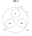
- Fig. 2 is a diagram illustrating one example of a configuration of the rotating filter provided at the light source apparatus.
- the rotating filter 33 has a disc shape and includes three openings provided at equal angles in a circumferential direction, and filters 33G, 33B1 and 33B2 are respectively attached to the three openings.
- the filter 33G transmits a band of a green (G) wavelength band
- the filters 33B1 and 33B2 transmit a band of a blue (B) wavelength band.
- a G illumination light of a narrow band of 530 to 550 nm centering around 540 nm passes through the filter 33G
- a B illumination light hereinafter, referred to as a B1 illumination light
- a B illumination light hereinafter, referred to as a B2 illumination light
- the B1 illumination light and the B2 illumination light of a narrow band which pass through the filters 33B1 and 33B2 are lights of the same wavelength band.
- the center of the rotating filter 33 is attached to a rotating shaft of a rotation motor which is not illustrated, so that the rotating filter 33 is rotationally driven.
- An encoder which is not illustrated is attached to the rotating shaft, or the like, of the rotation motor, and rotation of the rotation motor, that is, rotation of the rotating filter 33 can be detected by the encoder.
- the image processing apparatus 4 which will be described later controls rotation of the rotation motor so that a rotating speed of the rotating filter 33 becomes constant (not illustrated).
- an image of the subject is picked up using an illumination light of a narrow band from the light source apparatus 3. Therefore, compared to a case where an illumination light of a wide band which is normally widely used is used, there is a case where an amount of illumination light may not be sufficient. Particularly, because of optical transmission characteristics with the light guide fiber 26, a transmission loss tends to be greater at a short wavelength B side, and an amount of the emitted light of the B illumination light is likely to be small in a case where an illumination light is emitted from the illumination lens 23 of the distal end portion 22.
- two filters 33B1 and 33B2 having the same transmission characteristics are disposed in the circumferential direction of the rotating filter 33, the B illumination light is radiated twice on the same portion of the subject which is an observation target every time the rotating filter 33 rotates one revolution using the two filters 33B1 and 33B2, and an image is picked up twice based on the B illumination light using the return light.
- the rotating filter 33 one revolution in a 1.5 frame period, an image is picked up twice using the B illumination light.
- brightness of the picked up image (B picked up image) based on the B illumination light is improved.
- a picked up image with sufficient brightness cannot be obtained from only one of the B1 illumination light and the B2 illumination light of a narrow band
- a picked up image based on one B illumination light is combined with a picked up image based on the other illumination light according to brightness, so that a picked up image with sufficient brightness can be obtained while suppressing image quality degradation.
- the image processing apparatus 4 controls brightness according to sense of an operator by obtaining brightness of the picked up image through color conversion matrix processing.
- the CCD 25 of the endoscope 2 outputs a G picked up image based on the return light of the G illumination light as a G signal, outputs a B1 picked up image based on the return light of the B1 illumination light as a B1 signal, and outputs a B2 picked up image based on the return light of the B2 illumination light as a B2 signal. That is, a video signal outputted from the endoscope 2 includes the G signal, the B1 signal and the B2 signal.
- the image processing apparatus 4 has an analog processing unit 41, an A/D converter 42, a color balance processing unit 48, a digital processing unit 43, a synchronism control unit 40, a synchronism memory 40a, a composite processing unit 45, a matrix processing unit 46, a D/A converter 47, a brightness calculation processing unit 44 and a light adjustment control unit 49.
- the analog processing unit 41 performs predetermined analog signal processing such as amplification processing on the video signal from the endoscope 2 and outputs the processed signal to the A/D converter 42.
- the A/D converter 42 converts the output of the analog processing unit 41 into a digital video signal and outputs the digital video signal to the color balance processing unit 48.
- the color balance processing unit 48 performs color balance adjustment by multiplying respective color signals (a G signal, a B1 signal and a B2 signal) included in the digital video signal outputted from the A/D converter 42 by a correction coefficient determined according to operation of a color balance adjustment switch (not illustrated) provided at a front panel of the image processing apparatus 4, and outputs the digital video signal subjected to the color balance adjustment to the digital processing unit 43.
- the digital processing unit 43 performs clipping processing based on clip luminance (clip level) Yc outputted from the brightness calculation processing unit 44 on the digital video signal outputted from the color balance processing unit 48 to thereby limit an upper limit value of a luminance value of the digital video signal subjected to the clipping processing to the luminance value Yc. Further, the digital processing unit 43 separates the above-mentioned digital video signal subjected to the clipping processing into a G signal, a B1 signal and a B2 signal and outputs the G signal, the B1 signal and the B2 signal to the synchronism control unit 40 and the brightness calculation processing unit 44.
- the synchronism control unit 40 stores the G signal, the B1 signal and the B2 signal outputted from the digital processing unit 43 in the synchronism memory 40a in which an R image, a G image and a B image are stored. Note that, for example, a G signal corresponding to 30 frames, a B1 signal corresponding to 30 frames and a B2 signal corresponding to 30 frames are stored in the synchronism memory 40a.
- the synchronism control unit 40 reads out a G signal, a B1 signal and a B2 signal for which color shift becomes minimum from the synchronism memory 40a and outputs the G signal, the B1 signal and the B2 signal to the composite processing unit 45.
- the brightness calculation processing unit 44 sequentially calculates brightness of a picked up image for each of 0.5 frame based on the G signal, the B1 signal and the B2 signal outputted from the digital processing unit 43.
- brightness is obtained by implementing the same matrix processing as the matrix processing performed when the picked up image is displayed on the monitor 5.
- illumination with the G illumination light and the B1 illumination light is used as master illumination which is always used for image pickup, while illumination with the G illumination light and the B2 illumination light is used as slave illumination which is accessorially used when brightness of the image is low.
- the brightness calculation processing unit 44 obtains luminance Y1 with the master illumination by utilizing the matrix processing by the matrix processing unit 52 based on the G signal and the B1 signal. Further, in order to obtain brightness of the picked up image with the slave illumination, the brightness calculation processing unit 44 obtains luminance Y2 with the slave illumination by utilizing the matrix processing by the matrix processing unit 52 based on the G signal and the B2 signal.
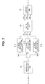
- Fig. 3 is a block diagram illustrating one example of a specific configuration of the brightness calculation processing unit.
- the average value calculating unit 50 calculates an SB1 signal, an SG signal and an SB2 signal which are average values of signals corresponding to the R image, the G image and the B image.
- An R image brightness calculating unit 51R, a G image brightness calculating unit 51G and a B image brightness calculating unit 51B respectively obtain brightness using the SB1 signal, the SG signal and the SB2 signal.
- a B1 signal is used as a signal of the R image
- a G signal is used as a signal of the G image
- a B2 signal is used as a signal of the B image.
- the R image brightness calculating unit 51R, the G image brightness calculating unit 51G and the B image brightness calculating unit 51B maintain the SB1 signal, the SG signal and the SB2 signal, and outputs the SB1 signal, the SG signal and the SB2 signal to the matrix processing unit 52 as Rf, Gf and Bf.
- the matrix processing unit 52 performs matrix operation related to color conversion by applying Rf, Gf and Bf outputted from the R image brightness calculating unit 51R, the G image brightness calculating unit 51G and the B image brightness calculating unit 51B to the following equation (1).
- the matrix processing unit 52 performs matrix processing on each of the master illumination and the slave illumination through the matrix operation using the following equation (1).
- ⁇ , ⁇ and ⁇ in the following equation (1) are matrix coefficients.
- Rm Gm Bm 0 ⁇ 0 0 0 ⁇ 0 ⁇ 0 ⁇ ⁇ Rf Gf Bf
- the matrix processing unit 52 supplies outputted values Rm, Gm and Bm obtained through the matrix processing on the master illumination or through the matrix processing on the slave illumination to the luminance calculating unit 53.
- a G signal is supplied as the outputted value Rm
- a B signal is supplied as the outputted value Gm
- a B signal is supplied as the outputted value Bm to the luminance calculating unit 53.
- the luminance calculating unit 53 obtains luminance Y1 with the master illumination by performing operation by applying the outputted value Rm (the G signal), the outputted value Gm (the B signal) and the outputted value Bm (the B signal) supplied from the matrix processing unit 52 to the following equation (2).
- the luminance calculating unit 53 obtains luminance Y2 with the slave illumination by performing operation by applying the outputted value Rm (the G signal), the outputted value Gm (the B signal) and the outputted value Bm (the B signal) supplied from the matrix processing unit 52 to the following equation (3).
- ⁇ Y1 ⁇ 0 that is, when target brightness can be obtained only with the master illumination
- the brightness calculation processing unit 44 sets a value of a composite ratio a (0 ⁇ a ⁇ 1) of the picked up image with the slave illumination at 0 and respectively sets values of clip luminance Yc and target luminance Ys at predetermined values.
- the brightness calculation processing unit 44 obtains a value of the composite ratio a through operation using the following equation (4) and respectively sets the clip luminance Yc and the target luminance Ys according to the obtained value of the composite ratio a.
- the matrix processing unit 46 which will be described later, generates a signal component of an RGB image from the G picked up image and the B picked up image obtained through image pickup using the narrow band light, through the matrix processing (color conversion matrix processing).
- the matrix processing at the matrix processing unit 52 of the brightness calculation processing unit 44 is the same processing as the matrix processing at the matrix processing unit 46. That is, the matrix operation by the brightness calculation processing unit 44 is performed to obtain a signal corresponding to an RGB input of the monitor 5, and luminance obtained by the brightness calculation processing unit 44 corresponds to luminance of the image displayed on the monitor and corresponds to brightness of the image sensed by the operator when the operator observes the monitor 5.
- the brightness calculation processing unit 44 outputs the composite ratio a obtained through the operation of the above-described equation (4) to the composite processing unit 45 and outputs clip luminance Yc set according to the value of the composite ratio a to the digital processing unit 43. Further, the brightness calculation processing unit 44 outputs the target luminance Ys set according to the value of the composite ratio a, and a difference value ⁇ Y1 to the light adjustment control unit 49.
- the light adjustment control unit 49 generates a light adjustment signal for adjusting a diaphragm amount of the diaphragm 34 based on the target luminance Ys and the difference value ⁇ Y1 outputted from the brightness calculation processing unit 44 and outputs the light adjustment signal. More specifically, the light adjustment control unit 49 generates a light adjustment signal for adjusting the diaphragm amount of the diaphragm 34, for example, so as to be close to the target luminance Ys outputted from the brightness calculation processing unit 44, that is, so that the value of the difference value ⁇ Y1 outputted from the brightness calculation processing unit 44 is close to 0 and outputs the light adjustment signal. With such control by the light adjustment control unit 49, the light amount of the G illumination light and the light amount of the B illumination light (the B1 illumination light and the B2 illumination light) are adjusted.
- the composite processing unit 45 combines the image picked up with the master illumination and the image picked up with the slave illumination based on the composite ratio a. That is, when the composite ratio a is 0, the composite processing unit 45 outputs the image picked up with the master illumination from the digital processing unit 43, that is, a signal obtained only using the G signal and the B1 signal to the matrix processing unit 46. Further, when the composite ratio a is not 0, the composite processing unit 45 combines the image picked up with the slave illumination, that is, a signal obtained from the G signal, the B2 signal and the composite ratio a with the signal based on the image picked up with the master illumination.
- the following equation (5) is an arithmetic equation used when the image picked up with the master illumination and the image picked up with the slave illumination are combined based on the composite ratio a.
- Rin, Gin and Bin in the following equation (5) indicate inputs of the R image, the G image and the B image. More specifically, in the narrow band light observation in the present embodiment, the B2 signal from the synchronism control unit 40 is inputted to the composite processing unit 45 as Rin in the following equation (5), the G signal from the synchronism control unit 40 is inputted to the composite processing unit 45 as Gin in the following equation (5), and the B1 signal from the synchronism control unit 40 is inputted to the composite processing unit 45 as Bin in the following equation (5). Further, Rt, Gt and Bt in the following equation (5) indicate outputs of the R image, the G image and the B image of the composite signal.
- Rt B2 in the following equation (5), the output of the R image supplied to the monitor 5 becomes substantially 0 through matrix processing which will be described later.
- G B ⁇ 1 B ⁇ 2 1 + a ⁇ G a ⁇ B ⁇ 2 + B ⁇ 1
- the composite processing unit 45 obtains a composite signal by performing operation using the above-described equation (5) and outputs the obtained composite signal to the matrix processing unit 46.
- the matrix processing unit 46 obtains a signal corresponding to an RGB input of the monitor 5 through matrix processing.
- the following equation (6) indicates an example of the matrix processing by the matrix processing unit 46.
- ⁇ , ⁇ and ⁇ in the following equation (6) are matrix coefficients and set so as to be the same values as ⁇ , ⁇ and ⁇ in the above-described equation (1).
- Rout, Gout and Bout in the following equation (6) indicate outputs of the R image, the G image and the B image after the matrix processing.
- ⁇ , ⁇ and ⁇ can be changed according to color tone desired for narrow band light observation.
- the D/A converter 47 converts the output of the matrix processing unit 46 into an analog signal and outputs the analog signal to the monitor 5. That is, Rout, Gout and Bout in the equation (6) are provided to the monitor 5 as RGB inputs.
- the monitor 5 displays the narrow band light observation image according to the inputted RGB inputs.
- the operator connects the connector 27 of the endoscope 2 to the light source apparatus 3 and the image processing apparatus 4 as illustrated in Fig. 1 when the operator uses the endoscope apparatus 1.
- a connection state illustrated in Fig. 1 can be obtained.
- the operator puts the light source apparatus 3, the image processing apparatus 4 and the monitor 5 into an operation state by operating a power supply switch which is not illustrated and performs operation for narrow band light observation.
- a light radiated from the light source 31 is converted into a G illumination light, a B1 illumination light and a B2 illumination light of a narrow band by the narrow band filter 32 and the rotating filter 33, and supplied to the endoscope 2 after brightness is adjusted by the diaphragm 34.
- Each illumination light is sequentially and substantially continuously radiated, for example, in a cycle of 1/20 seconds from the illumination lens 23 toward the subject side via the light guide fiber 26.
- the CCD 25 picks up an optical image using return lights from the portion.
- a G signal, a B1 signal and a B2 signal respectively corresponding to the return lights of the G illumination light, the B1 illumination light and the B2 illumination light are obtained.
- the video signal including the G signal, the B1 signal and the B2 signal is provided to the image processing apparatus 4 from the endoscope 2.
- the B1 signal and the B2 signal which are signals obtained by picking up the image with the same exposure amount using the illumination light of the same wavelength band, can be obtained under substantially the same conditions except that there is a small timing difference within one frame.
- the video signal inputted to the image processing apparatus 4 is converted into a digital signal by the A/D converter 42 after the video signal is subjected to predetermined analog processing by the analog processing unit 41.
- the digital video signal from the A/D converter 42 is inputted to the digital processing unit 43 after the digital video signal is subjected to color balance adjustment by the color balance processing unit 48.
- the digital processing unit 43 performs clipping processing based on clip luminance Yc outputted from the brightness calculation processing unit 44 on the digital video signal outputted from the color balance processing unit 48, separates the digital video signal subjected to the clipping processing into a G signal, a B1 signal and a B2 signal and outputs the G signal, the B1 signal and the B2 signal to the synchronism control unit 40 and the brightness calculation processing unit 44.
- the brightness calculation processing unit 44 respectively calculates luminance Y1 with master illumination and luminance Y2 with slave illumination through the matrix processing at the matrix processing unit 52. Further, the brightness calculation processing unit 44 calculates a difference value ⁇ Y1 between the target luminance Ys and the luminance Y1, obtains a composite ratio a using the calculated difference value ⁇ Y1, and, further, sets values of the clip luminance Yc and the target luminance Ys according to the obtained value of the composite ratio a.
- the target luminance Ys is set at a predetermined initial value Ydb at a timing immediately after the image processing apparatus 4 is activated, and is set at a value according to the value of the composite ratio a when the image processing apparatus 4 is put into an operation state. More specifically, for example, the target luminance Ys is set at luminance Yt when the composite ratio a is equal to or greater than 0 and less than a predetermined threshold TH1 and is set at luminance Yu which is greater than the luminance Yt when the composite ratio a is equal to or greater than the predetermined threshold TH1 and equal to or less than 1.
- the brightness calculation processing unit 44 may set the target luminance Ys at luminance Yw which is equal to or greater than the luminance Yu regardless of the value of the composite ratio a.
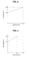
- Fig. 4 is a diagram illustrating one example of correlation between the composite ratio a and the clip luminance Yc.
- the clip luminance Yc may be set based on data in which correlation between the composite ratio a and the clip luminance Yc is specified as illustrated in Fig. 5.
- Fig. 5 is a diagram illustrating a different example from the example of Fig. 4 , of the correlation between the composite ratio a and the clip luminance Yc.
- the brightness calculation processing unit 44 outputs the composite ratio a obtained as described above to the composite processing unit 45 and outputs the clip luminance Yc set as described above to the digital processing unit 43. Further, the brightness calculation processing unit 44 outputs the target luminance Ys set as described above, and the difference value ⁇ Y1 to the light adjustment control unit 49.
- the light adjustment control unit 49 generates and outputs a light adjustment signal for adjusting a diaphragm amount of the diaphragm 34 based on the target luminance Ys and ⁇ Y1 outputted from the brightness calculation processing unit 44.
- the composite processing unit 45 obtains a composite signal by applying the composite ratio a outputted from the brightness calculation processing unit 44 to the above-described equation (5), and outputs the obtained composite signal to the matrix processing unit 46.
- the composite signal outputted from the composite processing unit 45 is provided to the matrix processing unit 46 where the composite signal is subjected to matrix processing, and signals of an R image, a G image and a B image in a display system can be obtained.
- the output of the matrix processing unit 46 is returned to an analog signal by the D/A converter 47 and supplied to the monitor 5.
- the present embodiment it is possible to set the target luminance Ys and the clip luminance Yc according to the value of the composite ratio a. Therefore, according to the present embodiment, for example, even if a pixel size of the CCD 25 is small (a saturation level is low), it is possible to suppress degradation of image quality caused due to variation of the saturation level for each pixel, so that it is possible to improve image quality of a narrow band light observation image compared to the conventional techniques.
- a composite signal having a minimum value of the composite ratio a may be selected from the respective composite signals accumulated in the memory and may be outputted to the matrix processing unit 46.
- a frame memory (not illustrated) which is capable of accumulating composite signals outputted from the composite processing unit 45 corresponding to a plurality of frames at the image processing apparatus 4, when the monitor 5 is instructed to display a freeze image, a composite signal for which a predetermined time period or less has elapsed from a timing of the instruction and for which the value of the composite ratio a is equal to or less than a predetermined value may be selected from the composite signals accumulated in the memory and may be outputted to the matrix processing unit 46.
- peripheral equipment such as an image filing apparatus
- setting of the peripheral equipment and setting of the image processing apparatus 4 may be switched in association with each other.
- information indicating positional relationship between a central position of the objective lens 24 and a central position of an effective pixel region of the CCD 25 may be stored in advance in a memory (not illustrated) provided at the endoscope 2, and position adjustment processing for adjusting the positions so that the central position of an observation image to be displayed on the monitor 5 is aligned with the central position of the objective lens 24, may be performed based on the information read from the memory.
- control may be performed so as to reduce a light amount of the light source 31.
- a plurality of scope switches which are capable of issuing various instructions according to operation of an operator may be provided at the endoscope 2, and an instruction which can be implemented may be assigned as appropriate through operation of the plurality of scope switches according to a result indicating a detected function which can be used in the endoscope 2 connected to the image processing apparatus 4.
- a light emission time period for enabling generation of a narrow band light observation image having brightness appropriate for observation may be set for each LED, and a frame rate at which a narrow band light observation image is displayed on the monitor 5 may be changed according to the set light emission time period for each LED.
- the light amount of the light radiated from the light source apparatus 3 may be adjusted to a light amount of a range beyond the range which can be adjusted with a diaphragm amount of the diaphragm 34.
- the light adjustment control unit 49 of the present embodiment may be configured to generate a light adjustment signal based on the target luminance Ys and ⁇ Y1 outputted from the brightness calculation processing unit 44 and a detection result of a light distribution state of the illumination light radiated from the light guide fiber 26.
Landscapes
- Health & Medical Sciences (AREA)
- Life Sciences & Earth Sciences (AREA)
- Surgery (AREA)
- Engineering & Computer Science (AREA)
- Physics & Mathematics (AREA)
- Biomedical Technology (AREA)
- Animal Behavior & Ethology (AREA)
- Radiology & Medical Imaging (AREA)
- Optics & Photonics (AREA)
- Nuclear Medicine, Radiotherapy & Molecular Imaging (AREA)
- Biophysics (AREA)
- Heart & Thoracic Surgery (AREA)
- Medical Informatics (AREA)
- Molecular Biology (AREA)
- Pathology (AREA)
- General Health & Medical Sciences (AREA)
- Public Health (AREA)
- Veterinary Medicine (AREA)
- Signal Processing (AREA)
- General Physics & Mathematics (AREA)
- Theoretical Computer Science (AREA)
- Endoscopes (AREA)
Applications Claiming Priority (2)
| Application Number | Priority Date | Filing Date | Title |
|---|---|---|---|
| JP2013062433 | 2013-03-25 | ||
| PCT/JP2014/051368 WO2014156253A1 (fr) | 2013-03-25 | 2014-01-23 | Dispositif endoscopique |
Publications (2)
| Publication Number | Publication Date |
|---|---|
| EP2942001A1 true EP2942001A1 (fr) | 2015-11-11 |
| EP2942001A4 EP2942001A4 (fr) | 2016-09-07 |
Family
ID=51623256
Family Applications (1)
| Application Number | Title | Priority Date | Filing Date |
|---|---|---|---|
| EP14774577.2A Withdrawn EP2942001A4 (fr) | 2013-03-25 | 2014-01-23 | Dispositif endoscopique |
Country Status (5)
| Country | Link |
|---|---|
| US (1) | US9545193B2 (fr) |
| EP (1) | EP2942001A4 (fr) |
| JP (1) | JP5747362B2 (fr) |
| CN (1) | CN104936503B (fr) |
| WO (1) | WO2014156253A1 (fr) |
Families Citing this family (5)
| Publication number | Priority date | Publication date | Assignee | Title |
|---|---|---|---|---|
| JP6152635B2 (ja) * | 2012-11-08 | 2017-06-28 | ソニー株式会社 | 画像処理装置および方法、並びに、プログラム |
| CN104166258B (zh) * | 2014-08-18 | 2017-02-15 | 深圳市华星光电技术有限公司 | 液晶面板的灰阶值设定方法以及液晶显示器 |
| US20190269309A1 (en) * | 2016-09-01 | 2019-09-05 | Hoya Corporation | Electronic scope and electronic endoscope system |
| US11601626B2 (en) * | 2017-03-09 | 2023-03-07 | Sony Corporation | Image processing apparatus and method |
| CN120018808A (zh) * | 2022-10-11 | 2025-05-16 | 奥林巴斯医疗株式会社 | 内窥镜系统、图像生成装置以及图像生成方法 |
Family Cites Families (10)
| Publication number | Priority date | Publication date | Assignee | Title |
|---|---|---|---|---|
| JP4270634B2 (ja) * | 1999-03-18 | 2009-06-03 | オリンパス株式会社 | 内視鏡装置 |
| WO2002007588A1 (fr) * | 2000-07-21 | 2002-01-31 | Olympus Optical Co., Ltd. | Endoscope |
| US6826424B1 (en) * | 2000-12-19 | 2004-11-30 | Haishan Zeng | Methods and apparatus for fluorescence and reflectance imaging and spectroscopy and for contemporaneous measurements of electromagnetic radiation with multiple measuring devices |
| JP4009626B2 (ja) * | 2004-08-30 | 2007-11-21 | オリンパス株式会社 | 内視鏡用映像信号処理装置 |
| JP5191090B2 (ja) * | 2005-07-15 | 2013-04-24 | オリンパスメディカルシステムズ株式会社 | 内視鏡装置 |
| JP5081720B2 (ja) * | 2008-05-22 | 2012-11-28 | 富士フイルム株式会社 | 蛍光内視鏡装置および励起光ユニット |
| CN102245078B (zh) * | 2009-05-14 | 2014-03-19 | 奥林巴斯医疗株式会社 | 摄像装置 |
| JP2010279454A (ja) * | 2009-06-03 | 2010-12-16 | Olympus Corp | 画像処理装置、画像処理方法、画像処理プログラムおよび撮像装置 |
| WO2012002115A1 (fr) * | 2010-06-28 | 2012-01-05 | オリンパスメディカルシステムズ株式会社 | Dispositif d'endoscope |
| WO2013031701A1 (fr) * | 2011-08-26 | 2013-03-07 | オリンパスメディカルシステムズ株式会社 | Dispositif d'endoscope |
-
2014
- 2014-01-23 JP JP2014532177A patent/JP5747362B2/ja active Active
- 2014-01-23 EP EP14774577.2A patent/EP2942001A4/fr not_active Withdrawn
- 2014-01-23 WO PCT/JP2014/051368 patent/WO2014156253A1/fr not_active Ceased
- 2014-01-23 CN CN201480005323.8A patent/CN104936503B/zh active Active
-
2015
- 2015-07-21 US US14/804,554 patent/US9545193B2/en active Active
Also Published As
| Publication number | Publication date |
|---|---|
| JP5747362B2 (ja) | 2015-07-15 |
| JPWO2014156253A1 (ja) | 2017-02-16 |
| CN104936503A (zh) | 2015-09-23 |
| CN104936503B (zh) | 2016-10-26 |
| US20150320301A1 (en) | 2015-11-12 |
| WO2014156253A1 (fr) | 2014-10-02 |
| EP2942001A4 (fr) | 2016-09-07 |
| US9545193B2 (en) | 2017-01-17 |
Similar Documents
| Publication | Publication Date | Title |
|---|---|---|
| JP5326065B2 (ja) | 内視鏡装置 | |
| US8979741B2 (en) | Endoscopic apparatus | |
| JP5623469B2 (ja) | 内視鏡システム、内視鏡システムのプロセッサ装置、及び内視鏡用制御プログラム | |
| US20150272422A1 (en) | Endoscope system, processor device, and method for operating endoscope system | |
| EP2008573B1 (fr) | Système d'observation biologique | |
| EP2371267A1 (fr) | Appareil d'endoscopie | |
| JP5623470B2 (ja) | 内視鏡システム、内視鏡システムのプロセッサ装置、及び内視鏡用制御プログラム | |
| US20150173595A1 (en) | Imaging apparatus | |
| US9545193B2 (en) | Endoscope apparatus | |
| EP1905344A1 (fr) | Endoscope et dispositif endoscope | |
| JP5670399B2 (ja) | 内視鏡システム及びそのプロセッサ装置並びに内視鏡システムの作動方法 | |
| US10349027B2 (en) | Imaging device and processing device | |
| JP6392486B1 (ja) | 内視鏡システム | |
| US12035892B2 (en) | Endoscope system, processor for endoscope, method of controlling endoscope system, and recording medium | |
| JP2016107003A (ja) | 医用画像処理装置及びその作動方法 | |
| EP3238604B1 (fr) | Dispositif de processeur et programme de commande pour un endoscope | |
| JP2011024726A (ja) | 画像処理装置 | |
| JP2015231467A (ja) | 内視鏡用光源装置及び内視鏡システム | |
| JP2015112208A (ja) | 医用システム | |
| EP3175774A1 (fr) | Système d'imagerie | |
| US10575721B2 (en) | Image pickup system and image processing apparatus |
Legal Events
| Date | Code | Title | Description |
|---|---|---|---|
| PUAI | Public reference made under article 153(3) epc to a published international application that has entered the european phase |
Free format text: ORIGINAL CODE: 0009012 |
|
| 17P | Request for examination filed |
Effective date: 20150721 |
|
| AK | Designated contracting states |
Kind code of ref document: A1 Designated state(s): AL AT BE BG CH CY CZ DE DK EE ES FI FR GB GR HR HU IE IS IT LI LT LU LV MC MK MT NL NO PL PT RO RS SE SI SK SM TR |
|
| AX | Request for extension of the european patent |
Extension state: BA ME |
|
| DAX | Request for extension of the european patent (deleted) | ||
| A4 | Supplementary search report drawn up and despatched |
Effective date: 20160809 |
|
| RIC1 | Information provided on ipc code assigned before grant |
Ipc: A61B 1/00 20060101AFI20160803BHEP |
|
| RAP1 | Party data changed (applicant data changed or rights of an application transferred) |
Owner name: OLYMPUS CORPORATION |
|
| RAP1 | Party data changed (applicant data changed or rights of an application transferred) |
Owner name: OLYMPUS CORPORATION |
|
| RIN1 | Information on inventor provided before grant (corrected) |
Inventor name: KOSHIKA, SOICHIRO Inventor name: ETO, TADAO Inventor name: IWASAKI, TOMOKI Inventor name: KAWATA, SUSUMU Inventor name: KUTSUMA, YUJI Inventor name: TANABE, TAKAHIRO Inventor name: KANEKO, KAZUMA Inventor name: HASHIMOTO, SUSUMU |
|
| STAA | Information on the status of an ep patent application or granted ep patent |
Free format text: STATUS: REQUEST FOR EXAMINATION WAS MADE |
|
| STAA | Information on the status of an ep patent application or granted ep patent |
Free format text: STATUS: THE APPLICATION IS DEEMED TO BE WITHDRAWN |
|
| 18D | Application deemed to be withdrawn |
Effective date: 20180801 |